

Page 1
AtmoCONTROL
SOFTWARE MANUAL
100% ATMOSAFE. MADE IN GERMANY.
www.memmert.com | www.atmosafe.net
Page 2

Willi-Memmert-Straße 90–96
We reserve the right to make changes
Page 3

AtmoCONTROL
About this manual
target group
This user manual describes the installation and use of the MEMMERT programming software
AtmoCONTROL. It is intended for use by trained personnel of the operator, who have the task
to the appliance. Incorrect use could result in damage to the appliance and/or to the chamber
with AtmoCONTROL and familiarise yourself with it.
This manual should always be kept in a place where those working with the software have
will work with the software are informed as to the whereabouts of this user manual. We rec-
The current version of AtmoCONTROL and this manual are available for download at
www.memmert.com/de/service/downloads/software/
www.memmert.com/de/service/downloads/software/
Page 4

4 D24042 | Date 09/2014
AtmoCONTROL
...........................................................................................................................
...........................................................................................................
....................................................................................................
......................................................................................................
...........................................................................................................
...........................................................................................................................
...............................................................................................................................
........................................................................................................................
........................................................................
.............................................................................................................................
.....................................................................................................
4. Programme 13
4.1 Editor window
4.1.1 Overview
4.1.2 Creating a programme
4.1.3 Setting parameters
4.1.4 Available parameters
4.2 Simulating the programme sequence (preview)
4.3 Saving, loading, transferring and running the programme
4.3.1 Saving the programme
4.3.2 Loading a saved programme
4.3.3 Transferring programme via Ethernet
4.3.4 Transferring a programme via USB storage medium
4.3.5 Selecting and starting a programme on the appliance
4.4 Programme examples
4.4.1 Programme example with clock timer
4.4.2 Programme example with door locking
4.4.3 Programme example sterilisation
4.4.4 Programme example loop
Page 5

AtmoCONTROL
...........................................................................................................................
..............................................................................................................................
......................................................................................................................
...................................................................................................................................
..................................................................................................................
Page 6
AtmoCONTROL
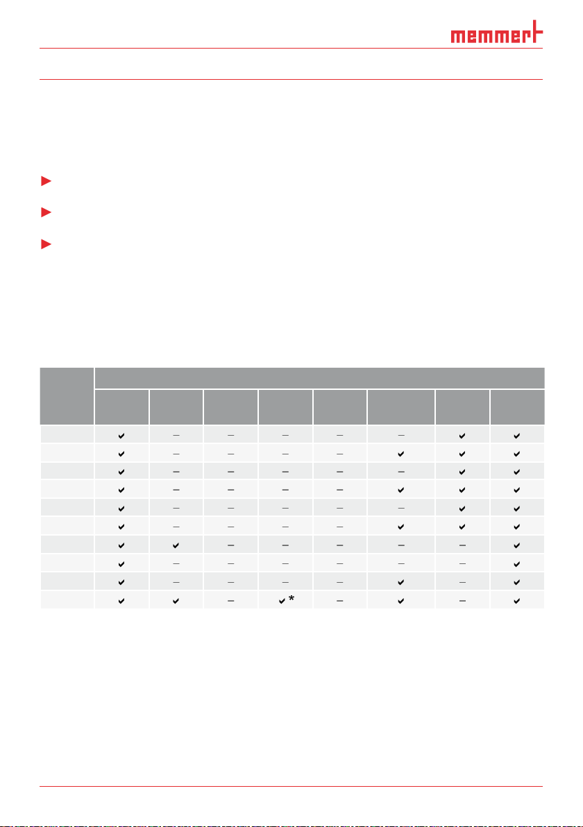
AtmoCONTROL is a software for programming and logging MEMMERT appliances of the
With AtmoCONTROL, you can
Appli-
the appliance itself.
ance
Tempe-
rature
Humi-
dity
Programmable main parameter
Pressure CO
2
O
2
Fan speed Air fl ap Light*
Page 7
AtmoCONTROL
Category Minimum system requirements
Available free space on
4 GB
VGA graphics and colour monitor
Windows 7, Windows 8
You must have administrator rights to be able to install AtmoCONTROL.
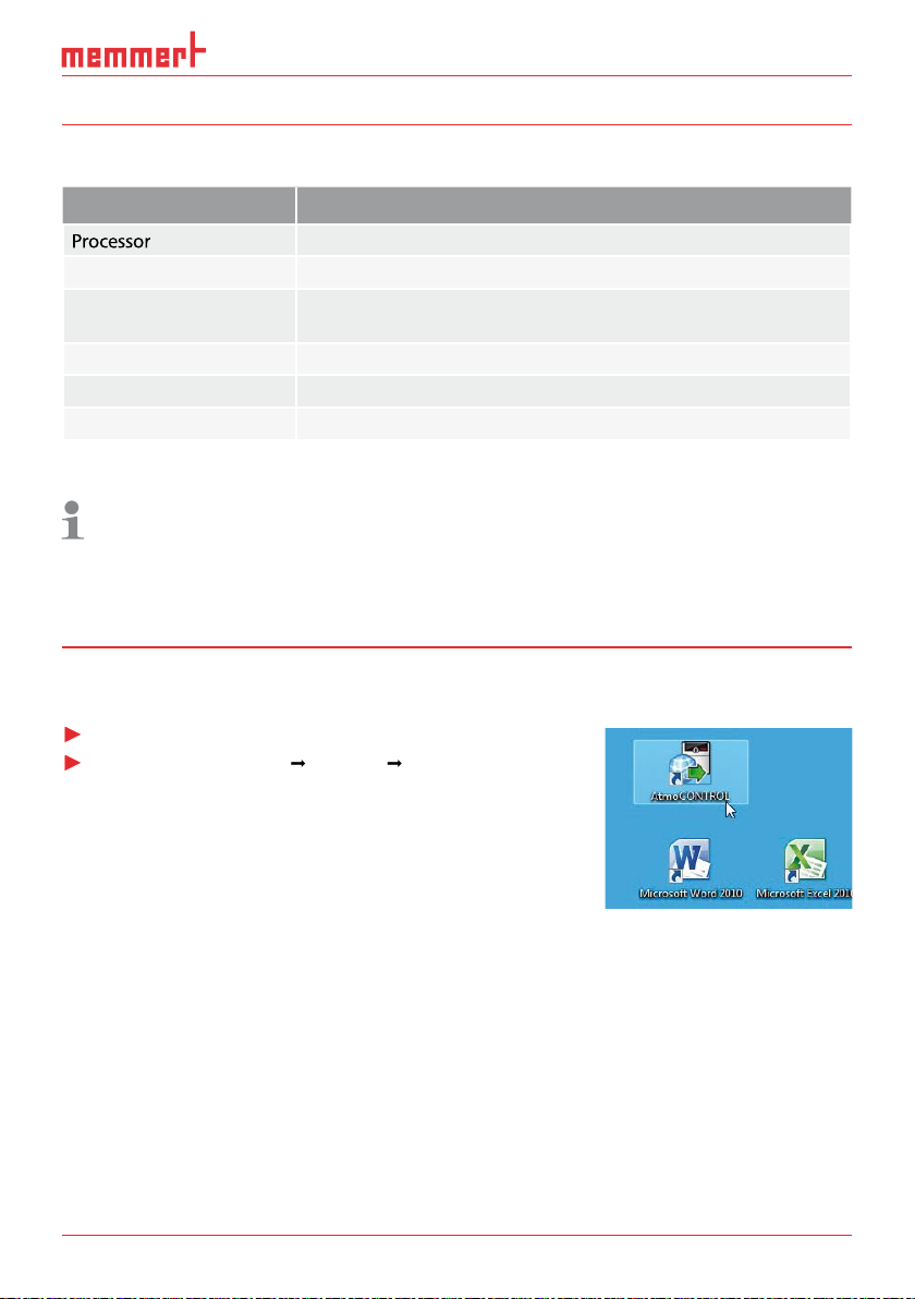
Working with AtmoCONTROL
AtmoCONTROL can be started in two ways:
AtmoCONTROL)
Page 8
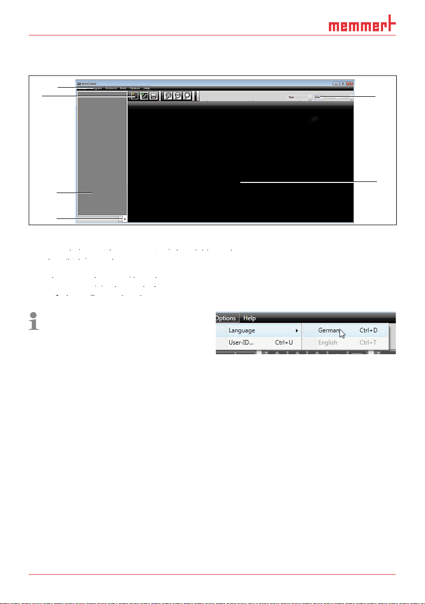
AtmoCONTROL
The
1
4
Menu bar (see section 3.2.1)
2
3
Status bar (provides an overview of available appliances, see page 10)
4
Show/hide status bar
Status bar (provides an overview of available appliances, see page 10)
Status bar (provides an overview of available appliances, see page 10)
5
Editor, simulation and protocol window (only for appliances listed on page 6,
otherwise only protocol window)
Editor, simulation and protocol window (only for appliances listed on page 6,
Editor, simulation and protocol window (only for appliances listed on page 6,
Programming mode switch (for editor/simulation/protocol, see pages 22 and 28)
otherwise only protocol window)
otherwise only protocol window)
You may change the
2
3
6
5
Page 9
AtmoCONTROL
Device Program Protocol Print Options Help
Connect to device via
Ethernet (see page 10)
2
protocol data on USB
storage medium (see
protocol data on USB
protocol data on USB
page 11)
3
database file (see page
4
Disconnect selected de-
vice (see page 12)
5
Disconnect all devices
vice (see page 12)
vice (see page 12)
Load a saved programme
8
Save programme
9
Save programme under a
Save programme
Save programme
new name
device via Ethernet (see
page 23)
Export programme to
page 23)
Import protocol from
page 23)
page 23)
page 28)
Export protocol data (see
page 28)
page 28)
page 29)
Print (see page 29)
guage (German/English)
page 29)
Automatic sending of
page 29)
page 29)
emails (see page 30)
Automatic sending of
Automatic sending of
Edit backup folder (see
emails (see page 30)
emails (see page 30)
page 31)
Programme information
page 31)
page 31)
20
format
21
Install device licence (see
page 10
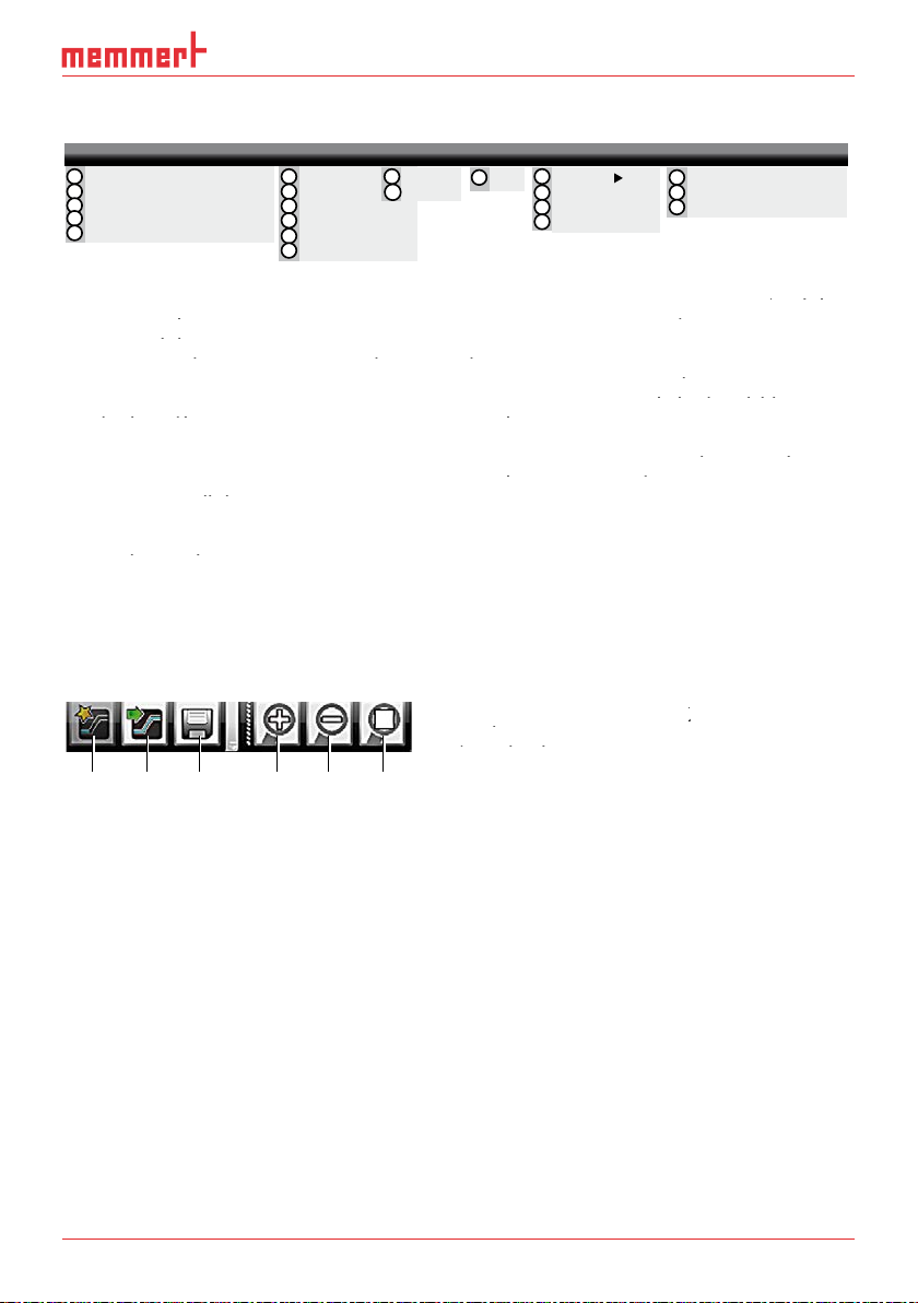
Toolbar
The toolbar provides rapid access to the most important menu functions:
programme
Load programme
programme
programme
from the data
Load programme
Load programme
medium
3
Save new
programme
Enlarge view
zoom in)
5
Reduce view
Show full
programme
Connect online via Ethernet
1
Connect offline from USB device
2
Connect offline from database
3
Disconnect device
4
Disconnect all devices
5
New
6
Load
7
Save
8
Save As...
9
Upload to Device
10
Export to USB drive
11
12
13
Import...
Export...
15
Print
14
Language
USER-ID
16
Email options
17
Edit Backup Folder
18
19
20
21
1 2 3 4 5 6
About...
User Manual
Upload license file to device
Page 10
D24042 | Date 09/2014
AtmoCONTROL
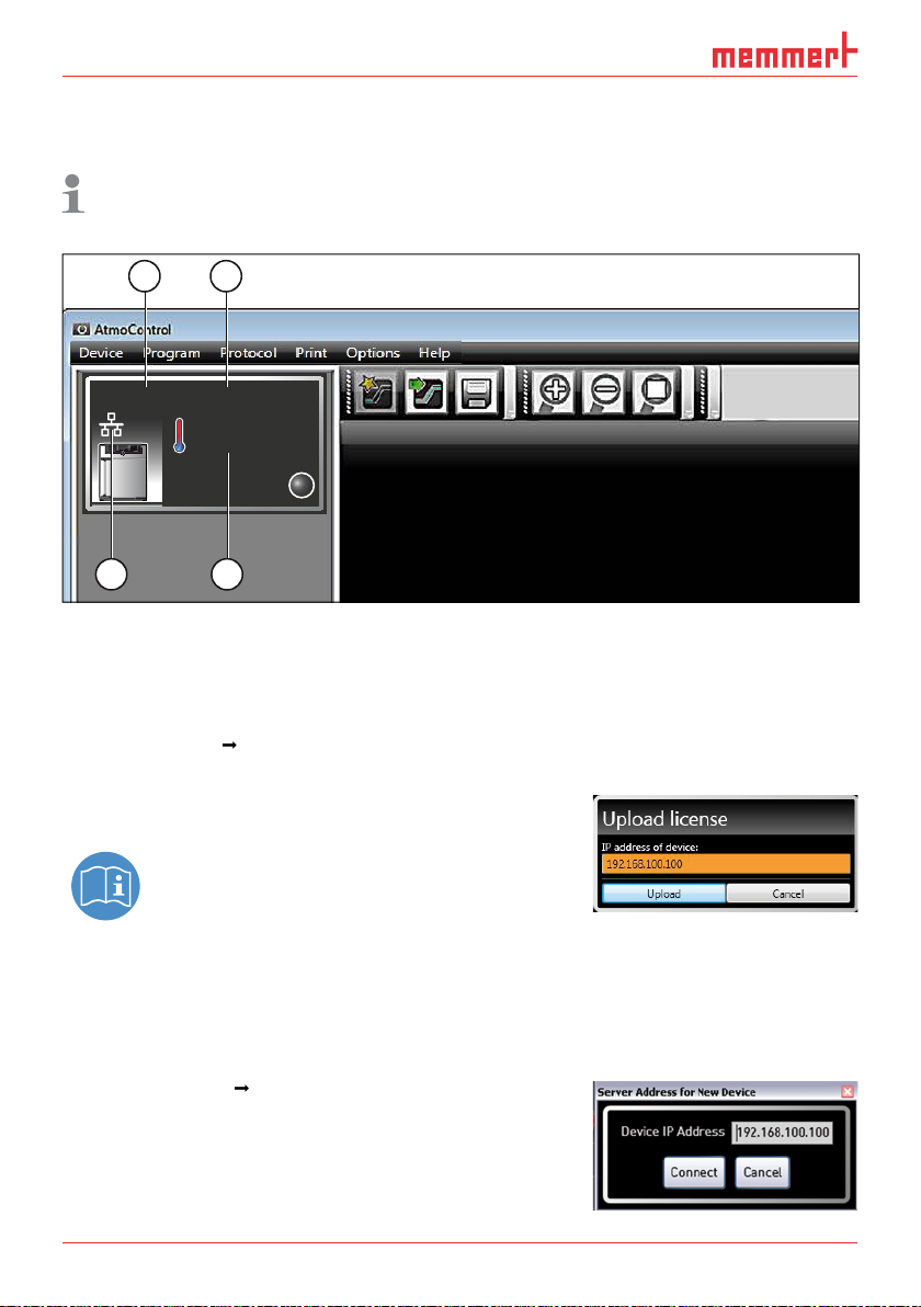
The status bar gives an overview of the appliances logged on to AtmoCONTROL. Appliances
1 2
Fig. 1
An appliance of type UF 260
(1), named "Laboratory" (2) by the user, is registered via Ether-
net (3) in AtmoCONTROL; current temperature 180.0 °C (4)
Installing
transfer the licence to.
A description of how to set the IP address is
tered) in AtmoCONTROL as described in the following section.
Adding and disconnecting devices
Adding device connected via Ethernet
vices have at delivery (192.168.100.100). The IP address
UF 260plus Laboratory
180.0°C
3 4
i
Page 11
AtmoCONTROL
A description of how to change the IP address of a device is provided in the user
Connecting device using USB storage
A description of how to read protocol data on a device is provided in the user
Connecting a device using
A window opens, in which you can open the
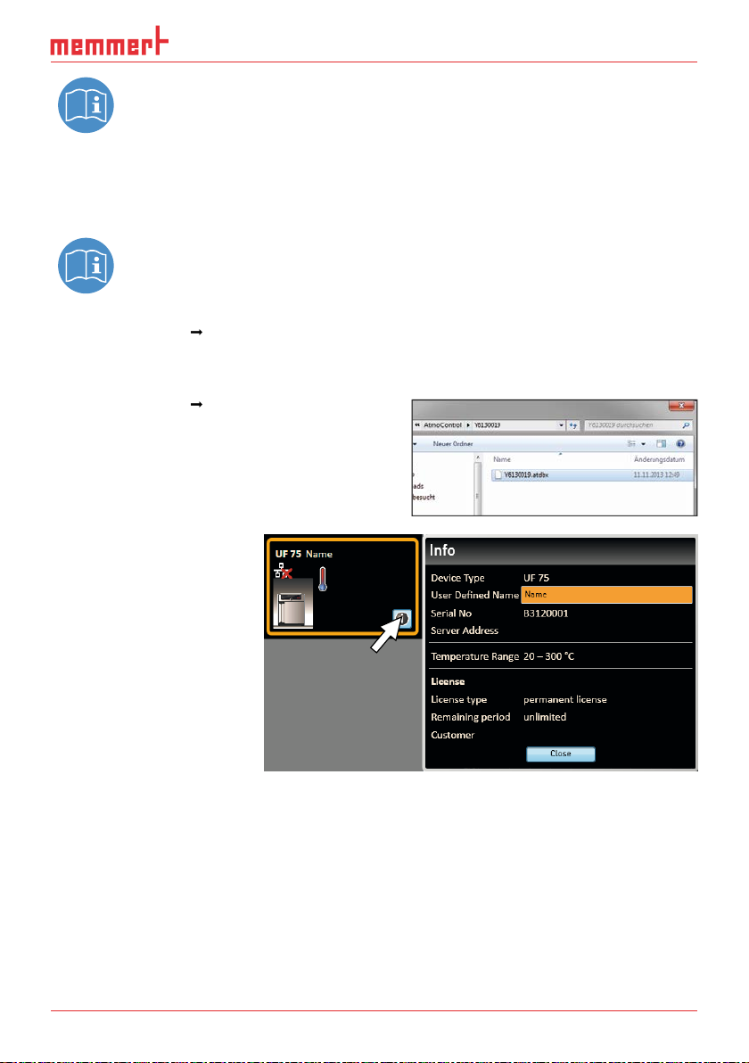
As soon as the appliance has
tion displayed at any time.
To do this, click on the
for your appliance later on,
Page 12

D24042 | Date 09/2014
AtmoCONTROL
Log fi le
file Log.txt is also transferred and saved in a subfolder of the directory
The log file is structured as shown in the
A
– End of the event
Alarm / event code
Alarm / event description
A detailed list of all event codes is given
from page 32.
Disconnecting devices
the status bar, select it and then click on
A B C D
Page 13

AtmoCONTROL
4.1.1
temperature, pressure and humidity), which the appliance then implements from a definable
To be able to create a programme in AtmoCONTROL, the appliance which is to perform the
4.1.2
Two editor threads are always shown for appliances with humidity or pressure control,
want to see the parameter values for a specific point in time, you must change to the simula-
tion mode (see page 22).
Fig. 2
Elements to create a programme
Appliance selected
Elements to create a programme
Elements to create a programme
2
Available parameters (functions)
Appliance selected
Appliance selected
3
Editor thread
Available parameters (functions)
Available parameters (functions)
4
Additional editor thread for appliances with humidity or pressure control
2
1
3
4
Page 14

D24042 | Date 09/2014
AtmoCONTROL
To create a programme, drag the individual parameter icons onto the editor thread one after
the zoom icons in the toolbar list (see section 3.2.2 on page 9) or with the mouse wheel,
you can zoom in or out of the display or have the entire programme displayed.
Ramp 05
Fig. 3
Drag the parameter icon (in this case a tem-
perature change) onto the editor thread while
holding the mouse button down
Fig. 4
Drag other parameters – light and a humidity
change in this case – onto the editor thread.
A red insertion mark helps you to find the
correct position.
The temperature icons (change/hold temperature) may only be placed on the upper editor
thread, humidity and pressure icons only on the lower one.
The meaning of the individual icons and the adjustment options are described from page
Removing a parameter icon from the editor thread
Removing a parameter icon from the editor thread
To remove a parameter
function) from an edi-
tor thread – if you have
with the mouse button
Fig. 5
with the mouse button depressed, to the recycle bin symbol.
10h:00m
11h:30m
Ramp 05
10h:00 m
11h:30 m
LIGHT
21.0 °C 180.0°C
180.0°C
21.0 °C 180.0°C
Increase
40.7%rh 70.6%rh
180.0°C
2h:30 m
0%
Page 15

AtmoCONTROL
4.1.3
To adjust values, click successively on the corresponding fields – in
the example on the right, the setpoint temperature. The value is
The adjustment range depends on the appliance for which the
The main parameters have additional adjustment options, which
fold down icon (Fig. 6, No. 1).
tolerance
Fig. 6
Further adjustment options fold down after clicking on the arrow icon on the right
edge of the window (1)
Fig. 6
Fig. 6
Further adjustment options fold down after clicking on the arrow icon on the right
Further adjustment options fold down after clicking on the arrow icon on the right
- - h:- - m
- - - .- °C21.0 °C
Ramp 01
21.0 °C
2
Tolerance band
1
0,1 K/min
11h:30m
37.0°C
Tolerance band
0,1 K/min
3
Page 16

D24042 | Date 09/2014
AtmoCONTROL
Available
Which parameters are available to adjust the programme depends on the appliance for
which a programme is to be created. Only those parameters are available that the appli-
Broad
parameter representation
parameter representation
Depiction
?
Function
Adjustment options
Adjustment options
)
Temperature to be maintained
Tolerance value above/below
Alarm if limits are exceeded
?
tempera-
ture
Function
Adjustment options
Adjustment options
Target (setpoint) temperature
Tolerance value above/below
3
When run, this is displayed in the
When
3
value is reached, even if the set time has already expired. If this is "off", the programme sequence is
in icon bar
Meaning Depiction on
editor thread
Function and
adjustment options
Tolerance band
Tolerance band
0,1 K/min
Page 17

AtmoCONTROL
Depiction
?
15
Function
Adjustment options
Adjustment options
)
tained
Tolerance value above/below
Alarm if limits are exceeded
?
15
Function
value.
Adjustment options
Adjustment options
Target (setpoint) humidity
Tolerance value above/below
3
When run, this is displayed in the
2
When
3
value is reached, even if the set time has already expired. If this is "off", the programme sequence is
in icon bar
Meaning Depiction on
editor thread
Function and
adjustment options
Hold
12h:00 m
70.0%rh
2h:30 m
40.7%rh 70.6 %rh
Tolerance band
+
0.0%rh
-
5.0%rh
on off
Alarm
Safe
Tolerance bandIncrease
+
5.0%rh
-
5.0%rh
on off
SPWT
Page 18

D24042 | Date 09/2014
AtmoCONTROL
Depiction
?
15
STAND BY
Function
Adjustment options
Adjustment options
)
Tolerance value above/below
Alarm if limits are exceeded
?
15
STAND BY
Function
value.
Adjustment options
Adjustment options
Target (setpoint) pressure
Tolerance value above/below
3
When run, this is displayed in the
2
When
3
value is reached, even if the set time has already expired. If this is "off", the programme sequence is
in icon bar
Meaning Depiction on
editor thread
Function and
adjustment options
hold p
decrease
1100mb
2h:30 m
500mb
2h:30 m
500mb
Tolerance band
+
20mb
-
10mb
on off
Alarm
Safe
Tolerance band
+
20mb
-
10mb
on off
SPWT
Page 19

AtmoCONTROL
Narrow
parameter representation
parameter representation
With the narrow
tive position – and remains active until it is changed by the insertion of a new parameter icon
Depiction
?
15
STAND BY
?
15
STAND BY
15
STAND BY
15
STAND BY
Air flap
15
STAND BY
15
STAND BY
15
STAND BY
Adjustment options: none
Appliance emits an acoustic signal at the
was inserted, for example if a specific setpoint
value is reached or the programme is finished.
in icon bar
Meaning Depiction on
editor thread
CO
2
50%
15
0
O2
CO2
12.0%
FAN
100%
FLAP
100%
LIGHT
Adjustment options/
comments
100%
UV LIGHT
on off
HORN
Page 20

D24042 | Date 09/2014
AtmoCONTROL
Depiction
15
STAND BY
Adjustment options: open/close
15
STAND BY
15
STAND BY
Activates the defrosting function of the appli-
15
STAND BY
The programme is repeated each week at the
STAND BY
CALENDAR
Year
30
05
2012
STAND BY
Synchronis-
finished on both editor threads.
finished.
in icon bar
15
Meaning Depiction on
editor thread
DOOR
openclose
SWITCH
A
openclose
DEFROST
CLOCK TIMER
Mo
Tu
We
Th
Fr
Sa
Su
11h:30 m
CALENDAR
Day
Month
Year
2012
- - - -h: m
22h:30 m
Adjustment options/
comments
18
05
SYNC
and or
Page 21

AtmoCONTROL
Depiction
STAND BY
The programme jumps back from the insertion
the range that is to be repeated.
... ...
in icon bar
Meaning Depiction on
editor thread
Adjustment options/
comments
STAND BY
JUMP
TARGET
STANDBY
LOOP
JUMP
4 X
TARGET
JUMP
TARGET
LOOP
LOOP
2 X
4 X
Page 22

D24042 | Date 09/2014
AtmoCONTROL
While creating the programme, you can display the prospective progression of all parameters
Fig. 7
Programme preview diagram (simulation)
you want to alter the programme.
Saving, loading, transferring and running the programme
4.3.1
The name with which you save the programme is later
4.3.2
Via
Page 23

AtmoCONTROL
4.3.3
Transferring programme via Ethernet
To be able to transfer a programme via Ethernet, the appliance and computer must be
4.3.4
Transferring a programme via USB storage medium
4.3.5
With appliances that have humidity control, make sure that the
water supply tank of the
vals, especially for programmes that run for long periods. The same applies for appliances
with gas supply.
Page 24

D24042 | Date 09/2014
AtmoCONTROL
4.4.1
5 841
Fig. 8
maintain this temperature (infinitely
) (4) until it is changed: also Monday to Friday (5) at 6
pm (6) to 50 °C (7) – again continued (infinitely
maintain this temperature (infinitely
maintain this temperature (infinitely
) (4) until it is changed: also Monday to Friday (5) at 6
) (4) until it is changed: also Monday to Friday (5) at 6
) (8) until it is changed again in the morning
at 8 am (2).
120 °C
50 °C
20 °C
2 3
6 7
347
8
Mo. Tu. We. Th. Fr. Sa. Su.
1
Page 25

AtmoCONTROL
3 4
Fig. 9
95.0
lowered (5) for 30 minutes (4) to 45.0
SPWT
on" (8) ensures that the door is opened only when the temperature really has dropped to
45.0
K/min (7).
1 2 5
Tolerance band
1,7 K/min
8 6
7
95 °C
45 °C
20 °C
1
6
3
2
5
12:00 h ≥ 0:30 h
Page 26

D24042 | Date 09/2014
AtmoCONTROL
4.4.3
4
Fig. 10
At the beginning, the fan is switched on to 100 % (1) and the air flap is closed (0 %) (2). Then,
Fig. 10
Fig. 10
the appliance heats up to 180.0
At the beginning, the fan is switched on to 100 % (1) and the air flap is closed (0 %) (2). Then,
At the beginning, the fan is switched on to 100 % (1) and the air flap is closed (0 %) (2). Then,
ting „Safe“ (5) ensures that the sterilisation time does not start (6) before the set tolerance band
the appliance heats up to 180.0
the appliance heats up to 180.0
6
Tolerance band
1 2 3
5
1
0 % 100 % 0 %
2
100 % 0 %
6
180 °C
4
3
20 °C
3:00 h
7
Page 27

AtmoCONTROL
9
41
Unload
Fig. 11
First, the appliance heats up to 250.0 °C (2) for one hour (1). Then, the fan begins to run at 80
Fig. 11
Fig. 11
fan is switched off (6). This sequence is repeated from the jump target (7) ten times (8).
250 °C
20 °C
27 3 5
6
0% 80% 0% 80% 0% 80% 0% 80% 0% 80% 0% 80% 0% 80% 0% 80% 0% 80% 0% 80% 0% 80% 0%
235
1 h 1 h 1 h 1 h 1 h 1 h 1 h 1 h 1 h 1 h 1 h 1 h 1 h 1 h 1 h 1 h 1 h 1 h 1 h 1 h 1 h 1 h
1 4
8
6 8
Page 28

D24042 | Date 09/2014
AtmoCONTROL
To be able to import a protocol via network, the appliance and computer must be con-
Fig. 12
Protocol display (example)
Importing protocol from USB data medium
At the appliance, protocols can be exported to an USB storage medium and imported in
AtmoCONTROL:
the user manual for the appliance.
files on an USB storage medium (see page 11).
Page 29

AtmoCONTROL
With
xport”, you can export a freely
types *.csv or *.xlsx (Excel), which can be processed in
With the
tions and protocols – depending on what is currently
You can set the language of the user
With the appliances listed in the table on page 6, it
AtmoCONTROL cannot generate a USER-ID file,
figuration in AtmoCONTROL is also not possible.
There can be only one USER-ID on a USER-ID USB stick. The settings in this file then apply for
A USER-ID identifier on a USER-ID USB stick for one (or several) serial numbers can be pur-
Fig. 13
Exporting protocols
Fig. 14
User-ID
Page 30

D24042 | Date 09/2014
AtmoCONTROL
with the USER-ID file into the
A window appears with the functions of the logged on appliance
that can be blocked (depending on the appliance type).
4.
Sending
AtmoCONTROL can automatically send an email to a freely definable recipient if an alarm
was triggered, e.g. if the temperature is exceeded. To make the corresponding settings, select
Fig. 15
Settings for the automatic sending of emails in case of alarm
events
Page 31

AtmoCONTROL
Backup folder
You can set up a backup folder in which
AtmoCONTROL saves backup copies of
You can either use the default folder or
Page 32

D24042 | Date 09/2014
AtmoCONTROL
Event codes of the log fi le Log.txt
Error codes for Generaon 2012 appliances Status: October 09, 2012
Error code
Parameter
Description
101: OS Error
Operang system error
102: File System Error
File system error
103: USB Error
USB error
104: GUI Error
Graphical user interface error
105: IP Stack Error
Ethernet error
106: I2C Bus Error
12C bus error
107: RTC Error
Realme clock error
108: RAM Disk Error
RAM disk error
109: WatchDog Reset
Watchdog error
Power Supply OK
110: Power Supply OK
111: Controller Restart
Restart aer reset
201: Config Error
Configuraon error
202: Calib User Error
Error in calibraon file (user)
203: Calib System Error
Error in calibraon file (calibraon system)
204: PID Config Error
Error in PID parameters
205: User Config Error
Error in user sengs
206: Baery Error
Baery low
207: SD Card Space
Warning at 95% disk space usage
208: SD Card Full
Error, SD card is full
209: SD Card Missing
SD card is missing
210: Failed To Copy Protocol
Error copying the protocol
211: Restauraon Failed
Error restoring LastState
212: Max Count Of Profiles
Maximum number of profiles on SD card reached
301: Fan Error
Fan speed error
302: Heang Error
Heang error
303: Temp Limitor
Temperature limiter has triggered
304: Door open
Door is opened
305: Hzg Err
200000
Triac optocoupler heang 1 power module 1
defecve
020000
Triac optocoupler heang 2 power module 1
defecve
Note:
002000
Triac optocoupler heang 1 power module 2
defecve
000200
Triac optocoupler heang 2 power module 2
defecve
000020
Triac optocoupler heang 1 power module 3
defecve
000002
Triac optocoupler heang 2 power module 3
defecve
100000
Triac heating 1 power module 1 defecve
010000
Triac heang 2 power module 1 defecve
001000
Triac heang 1 power module 2 defecve
000100
Triac heang 2 power module 2 defecve
In case of a hardware error of the oven, the controller displays the following error codes in a status /
error window, as well as logs them in the “Log.txt” file in the “Config” directory on the SD card.
The posion of the error number further specifies the posion of the error.
The posion of the red digit
indicates the defecve stage
of the appliance.
Page 33

AtmoCONTROL
000010
Triac heang 1 power module 3 defecve
000001
Triac heang 2 power module 3 defecve
306: Comm Err
1000
Power module 1 is not responding
0100
Power module 2 is not responding
0010
Power module 3 is not responding
0001
Humidity power module is not responding
401: Humidity Sensor
Humidity sensor defecve
402: Humidity Min Al
Humidity below minimum value
403: Humidity Max Al
Humidity maximum value exceeded
405: Temp Sensor Defunct
Temperature sensor defecve
404: Water tank empty
Water tank empty
406: Sensor Alarm
Monitoring sensor defecve
407: Temp Min Alarm
Temperature below minimum value
408: Temp Max Alarm
Temperature maximum value exceeded
409: Temp Auto Alarm
Temperature tolerance band violated
410: Lights Off
Automac lights switch-off
501: Sensor CO2 Error
CO2 sensor defecve
502: CO2 Empty
CO2 supply interrupted / gas cylinder empty
503: CO2 Auto Switch
Noficaon of gas cylinder change
504: CO2 Min Alarm
CO2 below alarm limit
505: CO2 Max Alarm
CO2 alarm limit exceeded
506: Sensor O2 Error
O2 sensor defecve
507: N2 Empty
N2 supply interrupted / gas cylinder empty
508: O2 Min Alarm
O2 below alarm limit
509: O2 Max Alarm
O2 alarm limit exceeded
601: Vacuum Sensor Error
Pressure sensor defecve
801: Program Start
602: No Shelf
No shelf inserted
603: Vacuum Min Alarm
Pressure below alarm limit
604: Vacuum Max Alarm
Pressure alarm limit exceeded
700: Power Min Border
Voltage below minimum limit
701: Device Fail me
me of power failure
702: Device Start Time
me of restart
Programme start
802: Program Cancelled
Programme cancellaon
803: Program End
Programme end
804: Invalid Program
Programme cannot be loaded
Page 34

D24042 | Date 09/2014
AtmoCONTROL
Air flap position 19
Appliance information 11
Appliance name 11
,
,
,
,
,
,
,
,
Target group 3
Tolerance band 15
Toolbar 9
,
W
Water supply tank 23
Zooming 9
Page 35

Page 36

AtmoCONTROL
D24042 | Date 09/2014
englisch
Memmert GmbH + Co. KG
Willi-Memmert-Straße 90-96 | D-91186 Büchenbach
Tel. +49 9122 925-0 | Fax +49 9122 14585
E-Mail: sales@memmert.com
facebook.com/memmert.family
Die Experten-Plattform: www.atmosafe.net
 Loading...