

Page 1
®
Memco
C100
Base 4 variant
Installation Guide
Ref No. C100 858 (GB) Version 4
The Memco C100 is a COP based emergency telephone system. It has been designed to provide quick and easy COP
installation and is also the rst emergency telephone that can be programmed at the touch of a button, making the
programming process quicker and easier than ever.
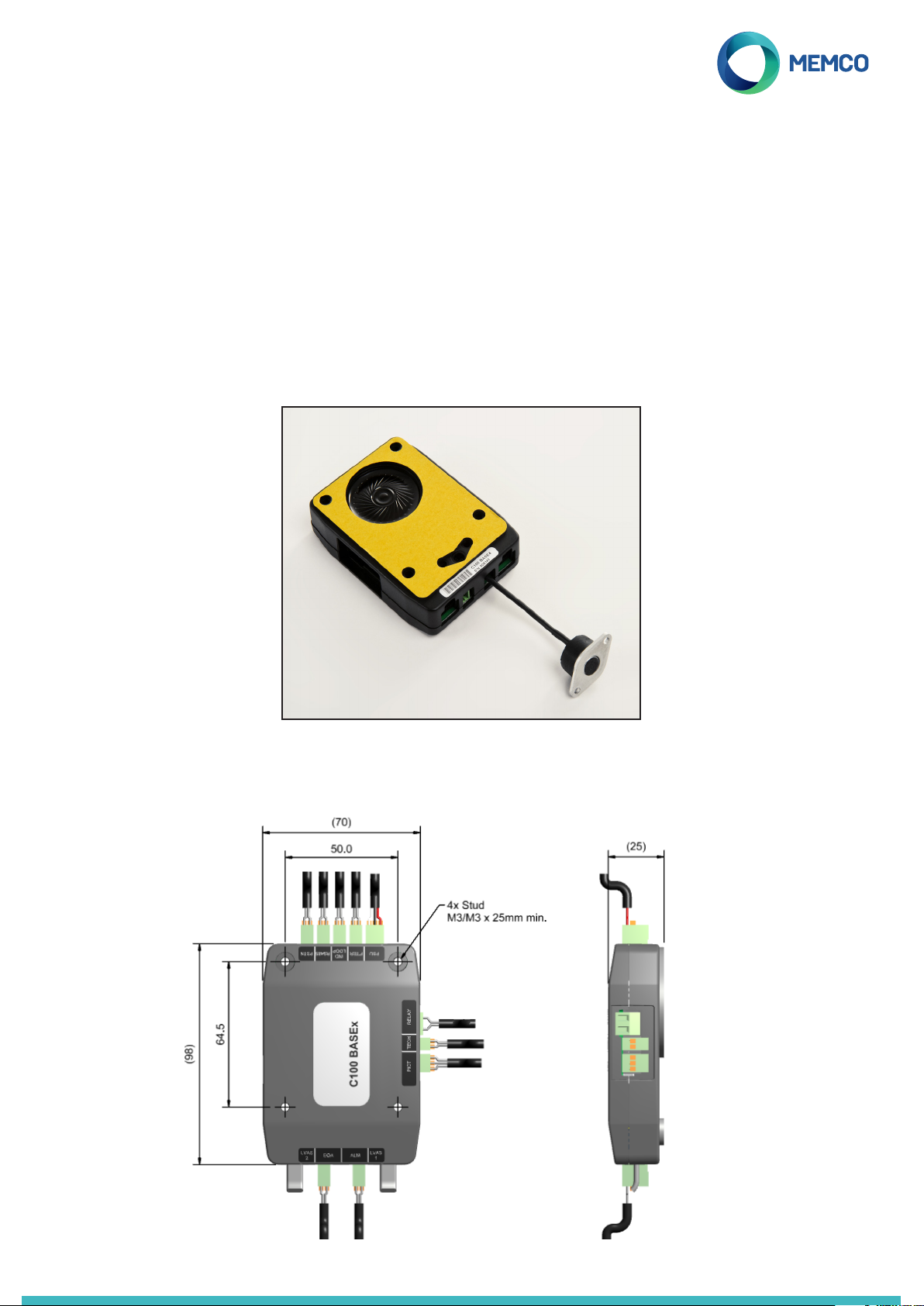
Model No. C100 BASE4
Dimensions (mm)
This Base 4 variant of the product can be installed
behind the COP and has an integrated relay, LED
indicators, inductive loop, and an external microphone.
Page 2
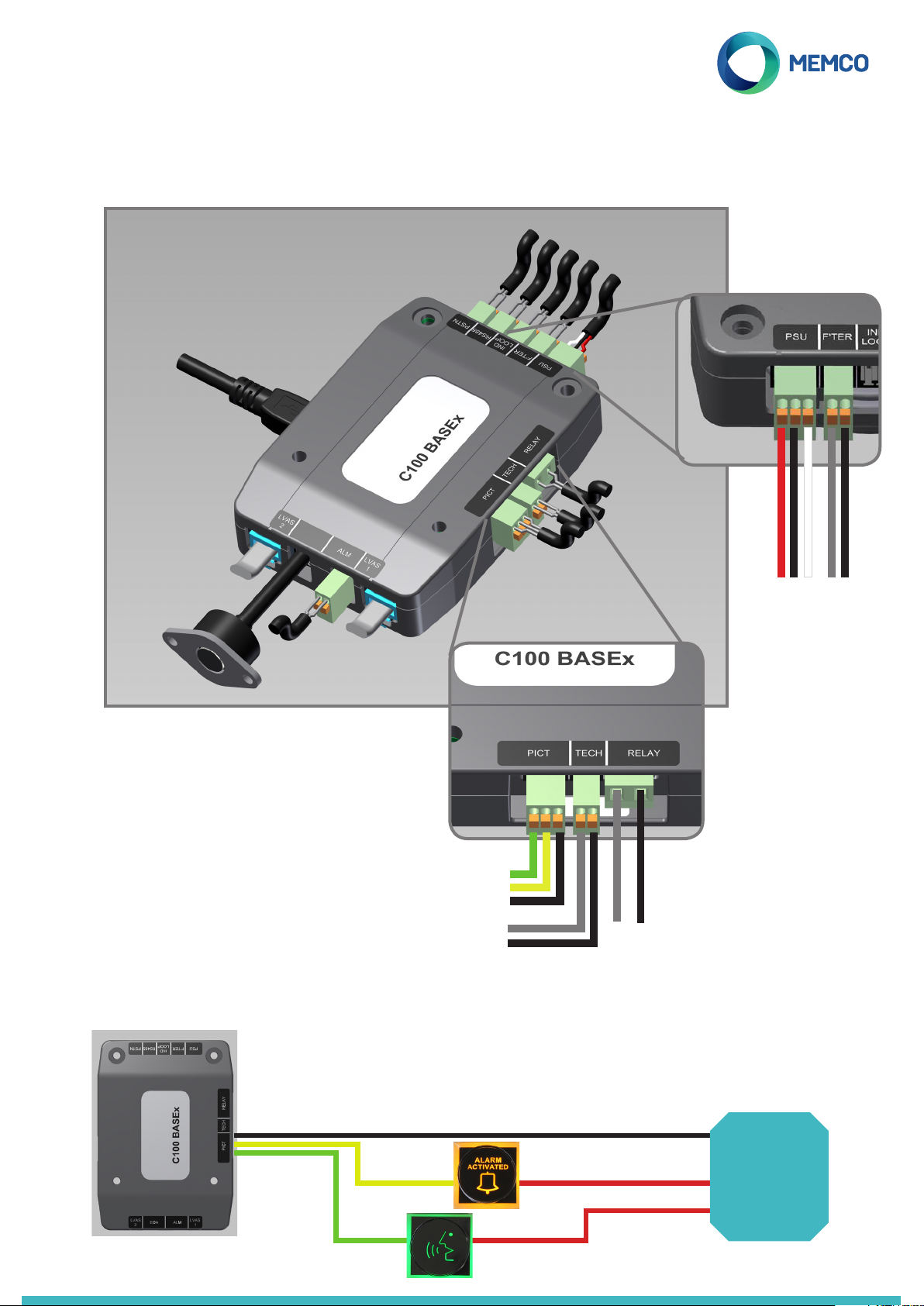
Connections to the Main Unit
Please see details below of all connections available on the C100 BASE4. All connections that have a specic polarity,
and require specic connections within the connector, are explained in the zoomed-in sections.
Telephone line (PSTN /GSM)
Serial (RS485)
Ind. Loop /Ext.Speaker
Alarm Filtering
10-30VDC PSU
C100 Programming Tool
Relay
Technical Input
LVAS/RAS 2
External Microphone
Alarm Button 0V
(Automatically detects
N/O or N/C)
0V return to pictogram power supply
LVAS/RAS 1
Call answered Pictogram
Call placed Pictogram
Isolated 0V return
5-24VDC Signal
Pictograms (0V)
MAX switching voltage of 60VDC or
42.4VAC (peak)/30VAC (rms)
Connecting External Pictograms
As long as external pictograms are powered by an independent power supply, the C100 can control their operation.
These pictograms should be connected as below:
0V
10-30VDC supply
5-24VDC Signal
Isolated 0V return
Power OK input signal (0V = on backup, 12V = on mains
Connections as per pictograms
connections detailed on the above
diagrams
OV
Voltage supply required
Voltage supply required
External
PSU
Page 3
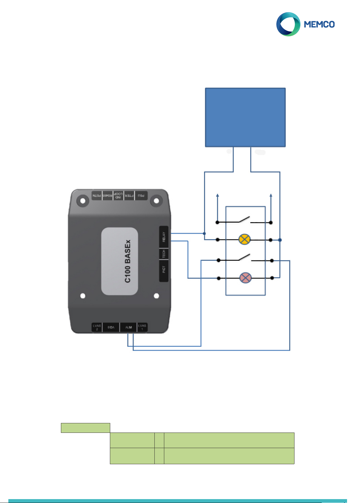
Connecting External Dual Illuminated Alarm Push
The diagram below shows the connections required to support a dual illuminated alarm push. The alarm push will require
a separate 12VDC power supply.
12VDC PSU
0V
To Lift Alarm cct
Back light
Call ans light
To Lift Alarm cct
12V
0V - unit automatically detects
N/O or N/C
The relay connections are used to trigger the illumination when the alarm push is activated. See below for programming.
Programming required for Relay Operation of External Dual Illuminated Alarm Push
Depending on how you wish the dual illuminated alarm push to operate you will need to set one of the following two
relay modes in the ‘Advanced > Relay Mode’ menu (NOTE: these are not the only options under the ‘Advanced > Relay
Mode’ see page 10 for full list).
Relay Mode >
SPEAK PICTO
BOTH PICTO
When the call centre answers an alarm call the relay contact will
û
close and trigger the illumination on the alarm push; alarm push
will remain lit until the call centre ends the call.
When the alarm button is pressed the relay contact will close
ü
triggering the illumination on the alarm push; alarm push will
remain lit until the call centre ends the call.
Page 4
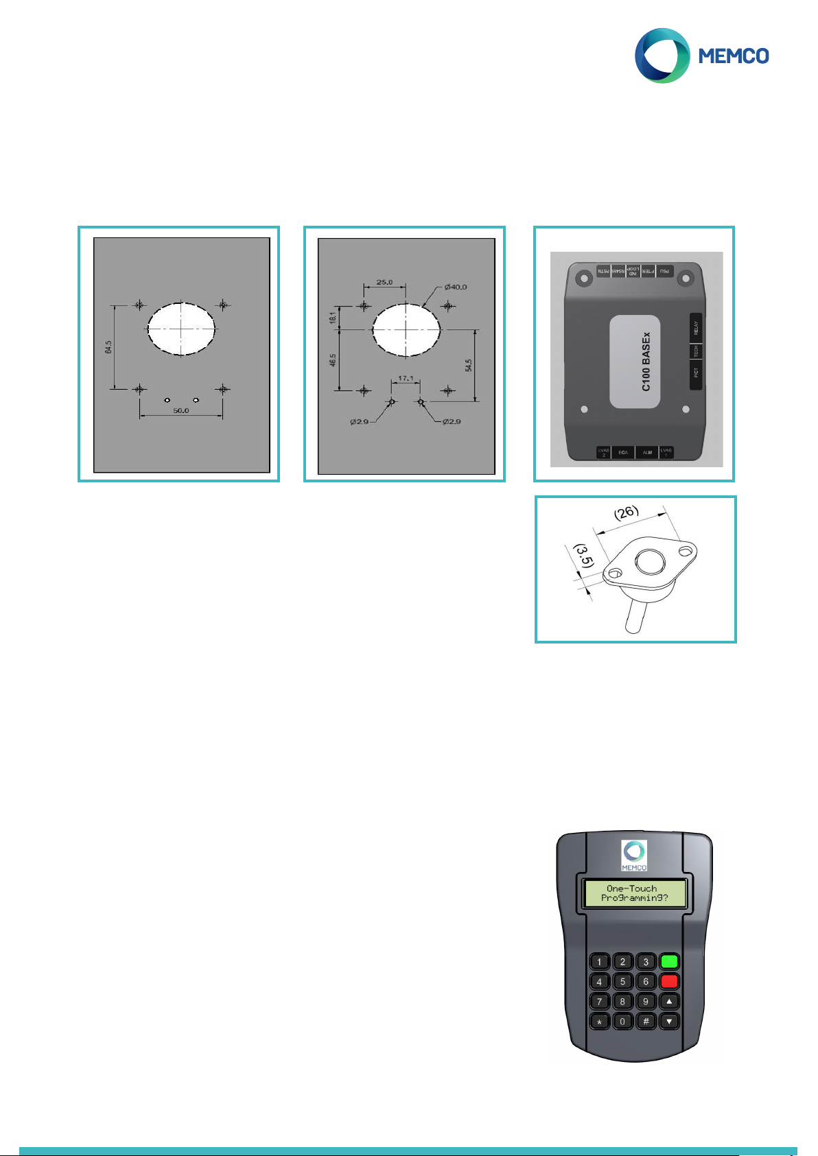
Fixing the unit behind the COP
Follow the simple steps below to install the C100 Base behind the COP panel.
1. Drill xing holes 2. Cut the grill pattern and
LED indicator holes
The C100 BASE is supplied with a self-adhesive gasket on the face of the unit.
In the absence of studs or screw holes in the COP the gasket may be used to
ax the C100 BASE to the COP.
To obtain optimum adhesion, the bonding surfaces must be clean, dry and
well unied. A typical surface cleaning solvent is isopropyl alcohol. Use proper
safety precautions for handling solvents.
3. Fix the unit in place
The external microphone is supplied with a 40mm long cable and mounting
plate (see image right).
Programming Options
+ One touch programming (using the programming tool)
+ Programming through the full product menu (programming tool)
+ Remotely via ‘Emergency Telephone Receiver’ (ETR) software (available from Avire) or a touch-tone telephone handset
Programming, at the touch of a button
1. Plug the programming tool into the C100 unit
2. If the C100 programming unit has a programming template set up, the
following message ‘One-touch programming?’ will appear
3. Press the übutton and the programming will be downloaded to the C100
unit automatically
If a location message needs to be recorded on the unit, press 1 to go into
programming mode and record the message in the following location on the
programming menu Messages> Location. To record the message:
• Press 2 to start recording
• Press # to stop recording
• Press 1 to play back the recorded message
Programming is now complete. You need only refer to the below sections of
the guide if more advanced programming is required.
Page 5
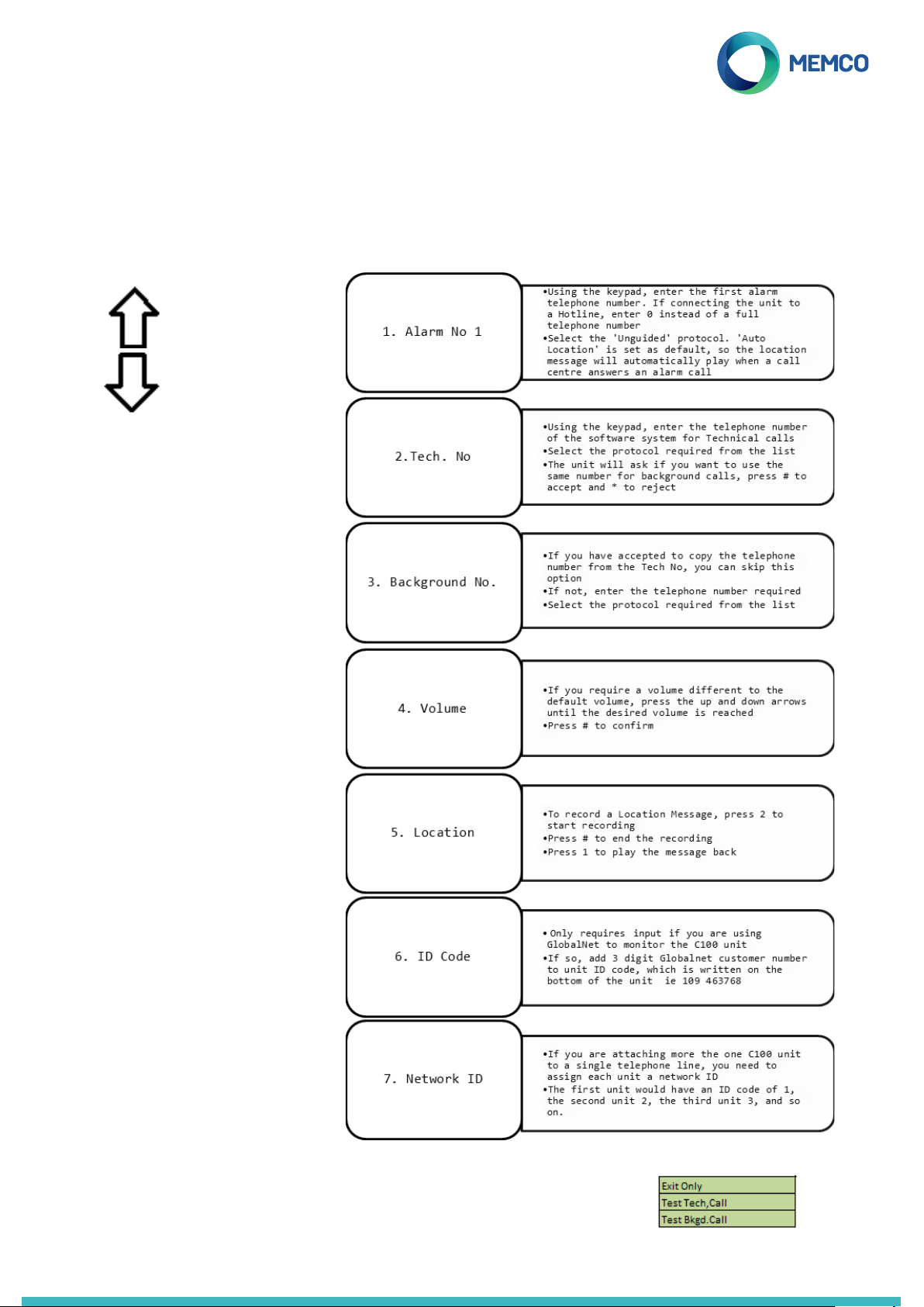
Programming controls and full menu
If you are not able to utilise the one touch programming, program the unit using the full product menu. Details of the
menu controls and quick start menu can be found below:
Menu controls Quickstart menu
Scroll up
Scroll Down
Forward / Accept
ü
Back / Cancel
û
ETR Software
The Memco C100 ETR software,
allows users to set up and maintain
their own database of lift emergency
telephones.
The software can be used to receive
emergency calls, test calls and
equipment monitoring for up to
4,000 lifts per system.
Additionally, the software can
remotely program the telephone
units, saving time and money and
reducing the number of site visits
required.
You have now nished the basic programming.
If you are in an option, press û to return to the
Quick Start Menu. Then, to exit programming
mode, Press û and select the action required
(by pressing ü) upon exiting from this list.
Page 6
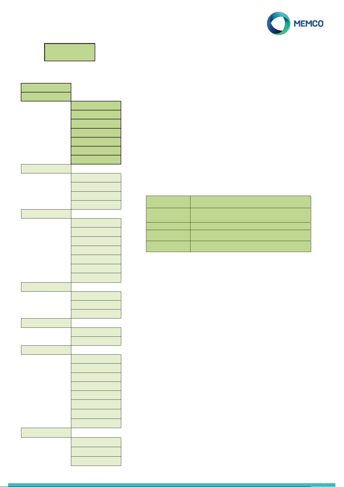
Full Programming Options
Status OK
1:Programming
Full Menu Structure
Quickstart >
Tel. Numbers >
Alarm no.1
Alarm no.2
Alarm no.3
Alarm no.4
Tech.no.
Background no.
Call attempts
Settings >
ID Code
Volume
System Cong >
HW Monitoring >
Delays >
COP delay
AS delay
Tech IP delay
Hangup delay
Answer delay
Redial del.
VAD timeout
Messages >
Location
Reassurance
Guidance
Time/Date >
Time
Date
Advanced >
Passcode
Network ID
Next EN81 call
PBX Frequency
Language >
Relay mode >
Relay override>
GMT Oset
Templates
Load Template
Save Template
Del. Template
If re-programming a unit, you will see the idle screen pictured here. Press 1 to enter
the programming menu for full programming options. It will only prompt you to enter a
password if one has been made active through selecting EN81-28 Mode.
Menu Sections explained...
Quick Start
The quick start menu consists of 7 menu options required for quick
setup. Please refer to the previous page in this guide for more
information.
Tel. Numbers
Alarm no.
Up to four alarm telephone numbers can be programmed in the C100
unit.
Using the keypad, enter the rst alarm telephone number.
When using a Hotline, (see System Cong) enter the telephone number
as 0.
Select a protocol required from this list
Guided Voice Unit will play a Guidance Message (see page 10) to the call centre when
Unguided Voice No message is played when a alarm call is answered.NOTE: If ‘Auto
Memco Protocol required if receiving background test calls with ETR
P100 Protocol required if receiving background test calls with P100 receiver
Contact ID Protocol required if receiving background test calls with ‘Contact ID’
answering an alarm call
Location’ has been selected in ‘System Cong+’ then the location
message WILL automatically play at the start of the call.
software
receiver software
Scroll to the preferred protocol and press ü to conrm.
Note: When connecting to a PBX/PABX, insert the number required to
get an outside line, followed by a pause (*), followed by the telephone
number. i.e.. 9*01344854000
If further alarm numbers are required, repeat this process for Alarm No.
2, Alarm No. 3 etc.
Tech. no.
The C100 can place Technical alert calls to signal faults with the system.
A Technical alert is a non-scheduled event e.g. from a Technical Input or
low battery with no main power.
All other diagnostics are checked during a scheduled Background Call
(see below). As standard this number is attempted the number of times
indicated by the 5th digit in Call Attempts (see below Call Attempts)
screen before waiting for the next technical alarm.
If using Avire ETR software select the ‘Memco’ protocol.
Background no.
To set up the EN81-28 three day test call (background test call)
programme the required telephone number here.
If using Avire ETR software select the ‘Memco’ protocol.
Call Attempts
The number of attempts the C100 will make to contact each telephone
number (maximum is 9 attempts per number).
The default is ‘999999’; each digit identies one of the six programmed
telephone numbers.
Page 7
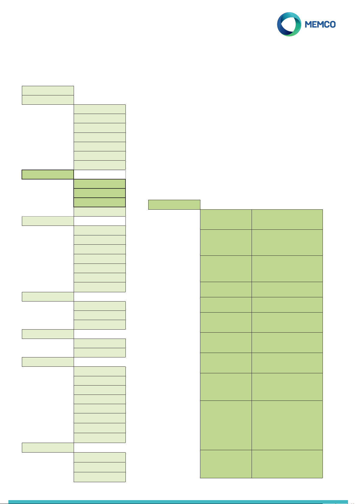
Full Programming Options
Full Menu Structure
Quickstart >
Tel. Numbers >
Settings >
Delays >
Messages >
Time/Date >
Advanced >
Templates
Alarm no.1
Alarm no.2
Alarm no.3
Alarm no.4
Tech.no.
Background no.
Call attempts
ID Code
Volume
System Cong >
HW Monitoring >
COP delay
AS delay
Tech IP delay
Hangup delay
Answer delay
Redial del.
VAD timeout
Location
Reassurance
Guidance
Time
Date
Passcode
Network ID
Next EN81 call
PBX Frequency
Language >
Relay mode >
Relay override>
GMT Oset
Load Template
Save Template
Del. Template
Menu Sections explained...
Settings
ID Code
If using Memco GlobalNet to monitor the C100 enter the following:
[3 digit customer number][Unit ID code]
Volume
Press the up and down arrows to adjust the volume, and press ü to
conrm.
System Cong
Sets how the system will operate. Select / deselect which modes of
operation are required in the system using the ü key. See below for a full
explanation of each option:
System Cong
Multi-dial
EN81-28 Mode
Consec. dial
Alt. dial tone
Verbal c/down
Passcode?
EOA pictogram
Alarm tone
Hotline
Auto Location
Avoid Silence
Sets the unit to call each of the
programmed alarm numbers one after
the other.
Prevents the unit from accepting
incoming calls when not in an alarm
state and requires a passcode to enter
remote programming.
Changes the dialling sequence; all
call attempts to the rst number are
completed before unit attempts to call
the second number and so on.
Allows system to work with an
intermittent dial tone.
Units gives a verbal countdown until
the emergency call is placed.
Require a passcode to be entered
before accessing the ‘System Cong’
menu.
Sets the system to keep the alarm
pictogram lit whilst the unit is in an
alarm state.
Sets the unit to emit a tone from the
internal speaker when the alarm push
is pressed.
Use if setting as a hotline. A hotline
is where the C100 will automatically
connect to another extension within
the building telephone exchange.
When an operator answers an alarm
call, the C100 will automatically play
the location message.
NOTE: when programming in the alarm
numbers ‘UNGUIDED’ protocol must
be selected (see section on Alarm
Numbers for more detail).
During an alarm call the C100 will not
mute its speaker, unless the operator
presses the ‘2’ key on their handset.
Page 8
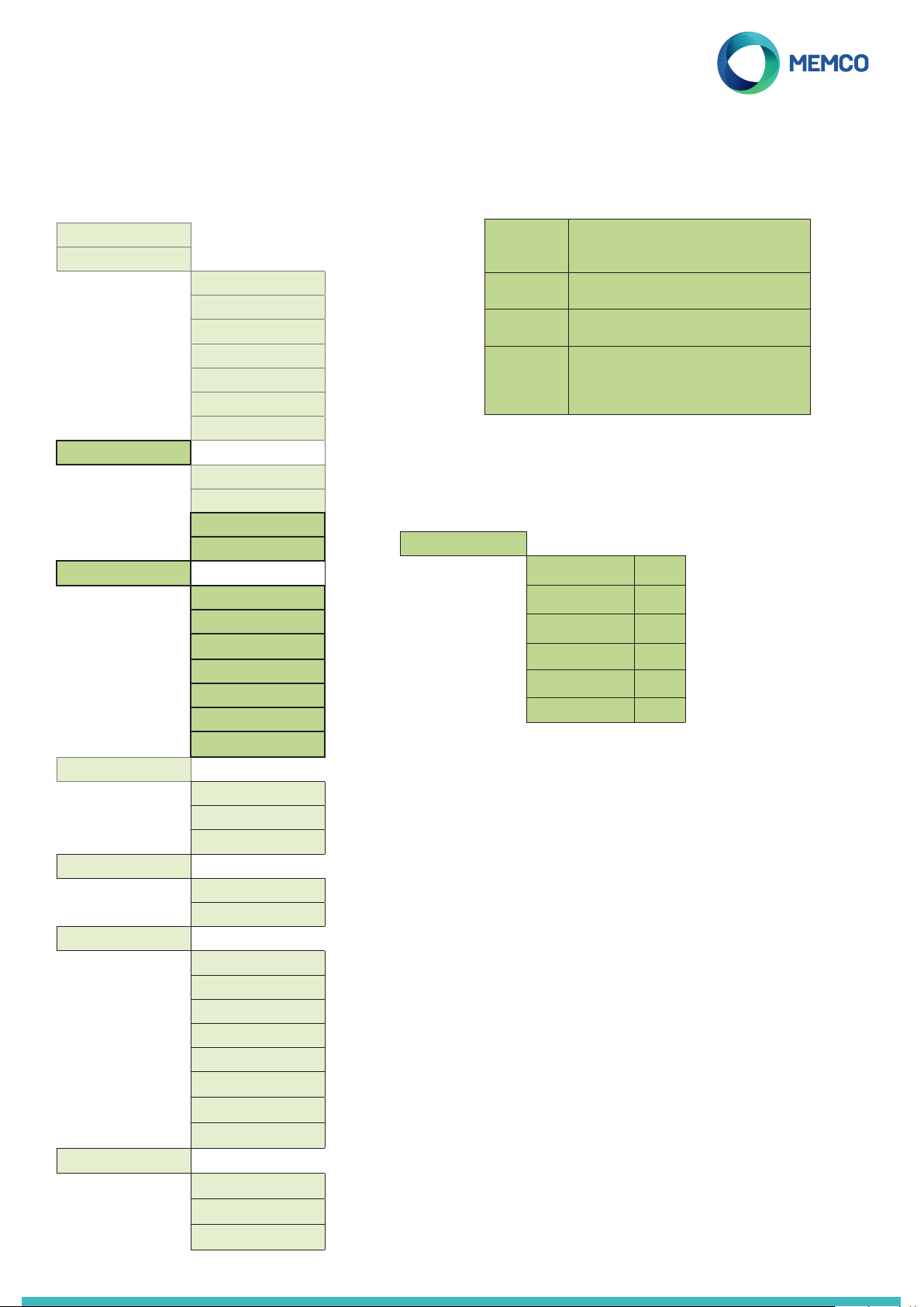
Full Programming Options
Menu Structure
Quickstart >
Tel. Numbers >
Settings >
Delays >
Messages >
Time/Date >
Advanced >
Templates
Alarm no.1
Alarm no.2
Alarm no.3
Alarm no.4
Tech.no.
Background no.
Call attempts
ID Code
Volume
System Cong >
HW Monitoring >
COP delay
AS delay
Tech IP delay
Hangup delay
Answer delay
Redial del.
VAD timeout
Location
Reassurance
Guidance
Time
Date
Passcode
Network ID
Next EN81 call
PBX Frequency
Language >
Relay mode >
Relay override>
GMT Oset
Load Template
Save Template
Del. Template
Menu Sections explained...
Quick dial
Quick VAD
Dialtone req.
Linet. Alert
HW Monitoring
Hardware monitoring sets which system elements are checked
whe the unit completes its self-check and places a test call.
Default settings are shown below:
HW Monitoring >
Delays
The delays can be set to alter the length of the delay before the unit
places a call.
COP delays - How long (in seconds) each of the alarm buttons, in the
COP, needs to be pressed before an emergency call is placed. Default
is 3 seconds
AS delay - Local voice alarm station (LVAS) and remote alarm station
(RAS). How long (in seconds) each of the alarm buttons needs to be
pressed before an emergency call is placed. Default is 3 seconds.
Tech delay - Relates to the delay before a technical call is placed,
upon receiving a fault signal from a connected third party device using
Technical Input.
Hang up delay - Sets time (in minutes) before C100 hangs up a call
(talk time).
Answer delay - the number of rings the C100 must detect before
answering any incoming calls. Where multiple C100 are sharing a line,
they must all have the same Answer Delay set.
Redial del. - Sets a delay (in seconds) between the C100 dialling
dierent numbers. A setting of 0 (the default setting) will de-activate
this feature.
VAD Timeout - Sets a time out (in seconds) whereby if the C100 does
not detect voice on the line it will automatically terminate the call. A
setting of 0 (the default setting) will de-activate this feature.
Reduces the dial tone detection test from 7 seconds
to 3 seconds – prevents issues with exchanges
timing out after 4 seconds.
Allows the C100 to detect speech before the rst
ring pulse has been sent down the line,
Requires the C100 to detect a dial tone before it
attempts to dial out.
If the phone line to the C100 is cut, the unit will
play an audible warning message. The message
will repeat every 3 minutes unit the phone line is
restored.
Power Supply
Battery
Phone Line
Spkr/mic.
AS
GSM Status
ü
ü
ü
ü
X
X
Page 9
Full Programming Options
Menu Structure
Quickstart >
Tel. Numbers >
Settings >
Delays >
Messages >
Time/Date >
Advanced >
Templates
Alarm no.1
Alarm no.2
Alarm no.3
Alarm no.4
Tech.no.
Background no.
Call attempts
ID Code
Volume
System Cong >
HW Monitoring >
COP delay
AS delay
Tech IP delay
Hangup delay
Answer delay
Redial del.
VAD timeout
Location
Reassurance
Guidance
Time
Date
Passcode
Network ID
Next EN81 call
PBX Frequency
Language >
Relay mode >
Relay override>
GMT Oset
Load Template
Save Template
Del. Template
Menu Sections explained...
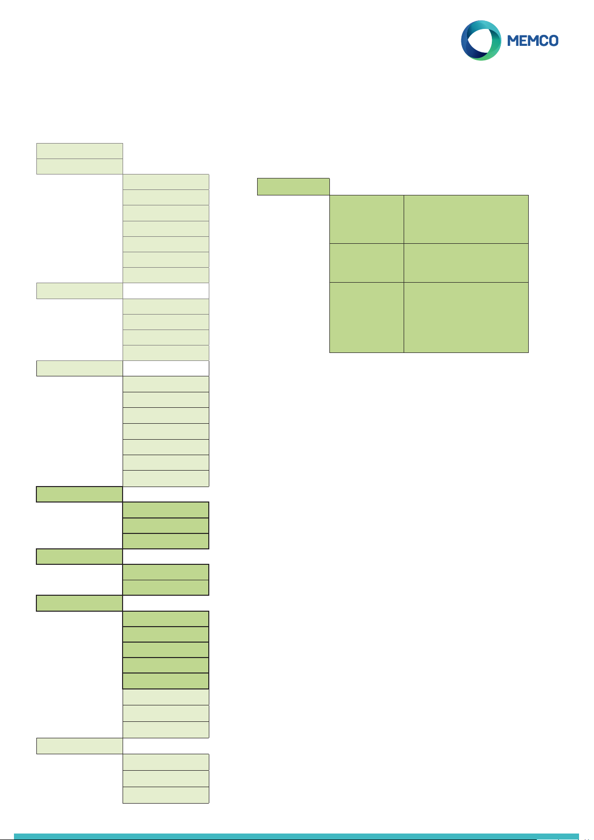
Messages
Messages >
Location
Reassurance
Guidance
Time / Date
The time and date can be set by entering the correct values and
conrm by pressing ü.
Advanced
Passcode
Enter the passcode required to enter standard programming mode
when EN81-28 mode is active. (up to 6-digits). From the idle screen
you will have to press * PASSCODE #
Network ID
Set an extension number 1-8 where units share a phone line. All unit
IDs on a system need to be unique.
Next EN81 call
Details the next scheduled Background call for the unit.
PBX Frequency
Sets disconnect tone frequency (40-2000Hz in 40Hz steps), if
connected to a PBX, which does not use standard tones.
Language
Tick the language required from the on-screen list provided.
This is the only message that needs
recording. The location message is played
to the call centre receiving the alarm call,
to inform them of the location of the lift.
This is the message played to trapped
passengers as an alarm call is being
placed
If the ‘Guided’ protocol has been
selected, this message will be played to
the call centre operator to ask them to
select whether to listen to the Location
message or to be connected to the lift car
immediately.
Page 10
Full Programming Options
Menu Structure
Quickstart >
Tel. Numbers >
Settings >
Delays >
Messages >
Time/Date >
Advanced >
Templates
Alarm no.1
Alarm no.2
Alarm no.3
Alarm no.4
Tech.no.
Background no.
Call attempts
ID Code
Volume
System Cong >
HW Monitoring >
COP delay
AS delay
Tech IP delay
Hangup delay
Answer delay
Redial del.
VAD timeout
Location
Reassurance
Guidance
Time
Date
Passcode
Network ID
Next EN81 call
PBX Frequency
Language >
Relay mode >
Relay override>
GMT Oset
Load Template
Save Template
Del. Template
Menu Sections explained...
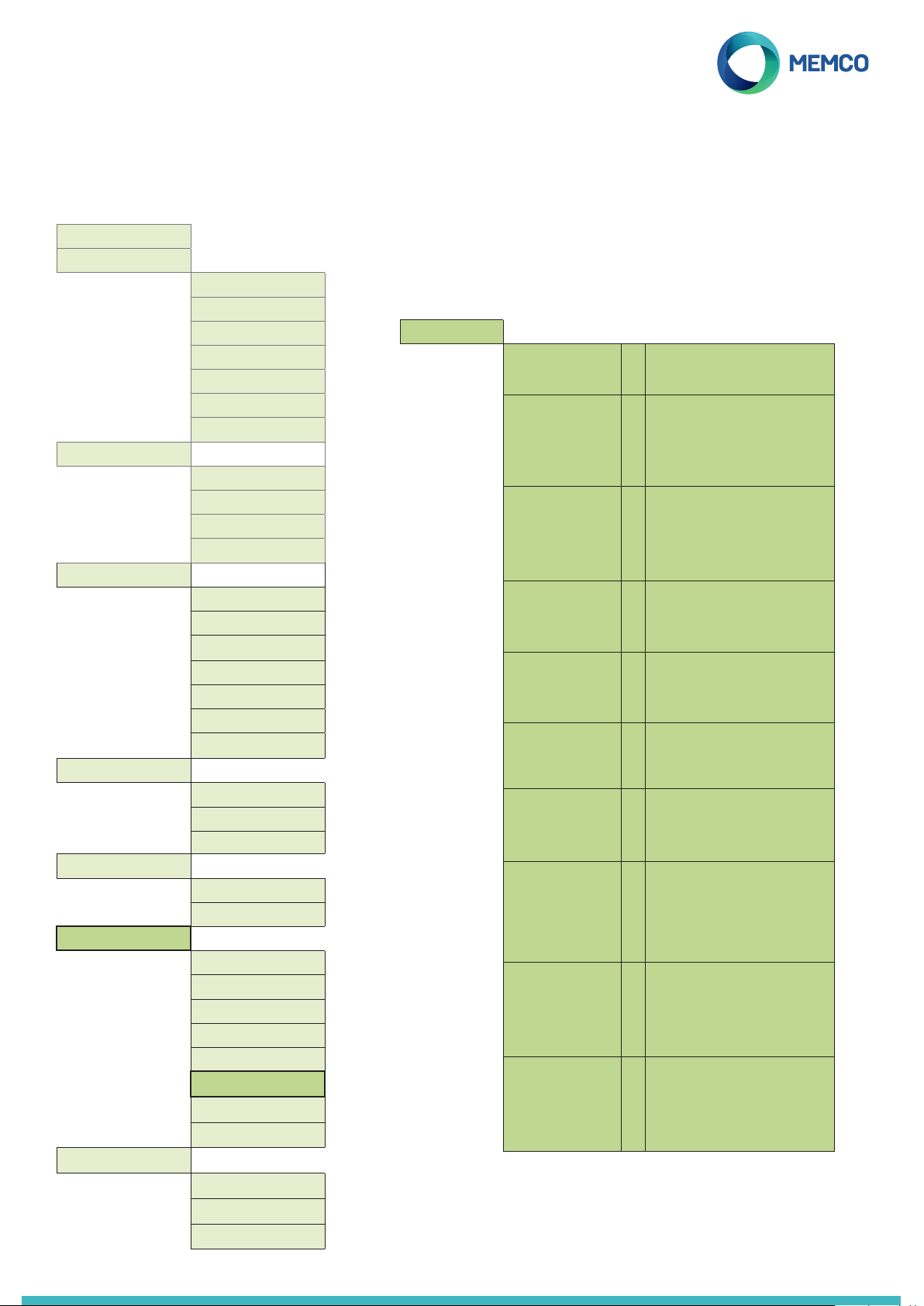
Relay Mode
The relay can be used to switch the power supply to an external
device (e.g. warning siren, door locking systems).
Relay Mode >
Siren
Door (NO/CMD)
Door (NC/CMD)
Door (NO/ALM)
Door (NC/ALM)
PSTN fault
Tech. fault
Emg. Lighting
Spk. Picto
Both Pictos
Relay contacts close when the Alarm
û
Push is activated, and open again after
the alarm push delay. Typically used to
trigger a siren on the lift car.
Door release mode, release on
û
command, default relay state is N/O:
The door release is only activated if the
operator presses the ‘8’ key on their
handset during the initial alarm call or
any follow-up calls. The release will then
remain activated until the call ends.
Door release mode, release on
û
command, default relay state is N/C:
The door release is only activated if the
operator presses the ‘8’ key on their
handset during the initial alarm call or
any follow-up calls. The release will then
remain activated until the call ends.
Door release mode, release on alarm
û
push, default relay state is N/O. The door
release is activated as soon as the Alarm
Pictogram is lit, and remains activated
until the End of Alarm signal is received.
Door release mode, release on alarm
û
push, default relay state is N/C. The door
release is activated as soon as the Alarm
Pictogram is lit, and remains activated
until the End of Alarm signal is received.
The relay contacts default to closed,
û
and open whenever a PSTN line fault
is detected. When the fault condition
is cleared, the contacts return to the
default closed state.
Technical fault mode - The relay
û
contacts default to the closed state,
opening whenever any technical fault
is detected by the Memcom+. Once the
fault condition has cleared, the contacts
close again.
Emergency lighting mode - the relay
û
contacts default to the open state,
closing within 1 second of a loss of
external power. This allows the use of
the relay to switch backup power to
emergency lighting hardware during an
external power failure. Once external
power is restored, the relay contacts
open again.
If a dual illuminated alarm push is
û
connected to the relay contacts:
When the call centre answers an alarm
call the relay contact will close and
trigger the illumination on the alarm
push; alarm push will remain lit until the
call centre ends the call.
If a dual illuminated alarm push is
ü
connected to the relay contacts:
When the alarm button is pressed the
relay contact will close triggering the
illumination on the alarm push; alarm
push will remain lit until the call centre
ends the call.
Page 11
Full Programming Options
Full Programming Options
Full Programming Options
Menu Structure
Menu Structure
Menu Structure
Menu Sections explained...
Advanced >
Passcode
Network ID
Next EN81 call
PBX Frequency
Language >
Relay mode >
Relay override>
GMT Oset
Templates
Load Template
Save Template
Del. Template
Load Template
1. Load a programming template onto the C100 telephone:
2. Select the required programming template from the list and
press ü
3. In the conrmation screen press ü to load the template or
press û to cancel
4. If no templates are saved to the C100 PT then the list will be
blank
Save Template
1. Save the current programming selection on the C100 PT as a
template:
2. Select (NEW TMEPLATE) and press ü
3. In the conrmation screen press ü to load the template or
press û to cancel
4. The C100 PT will automatically name the template (starting with
‘TEMPLATE 1’).
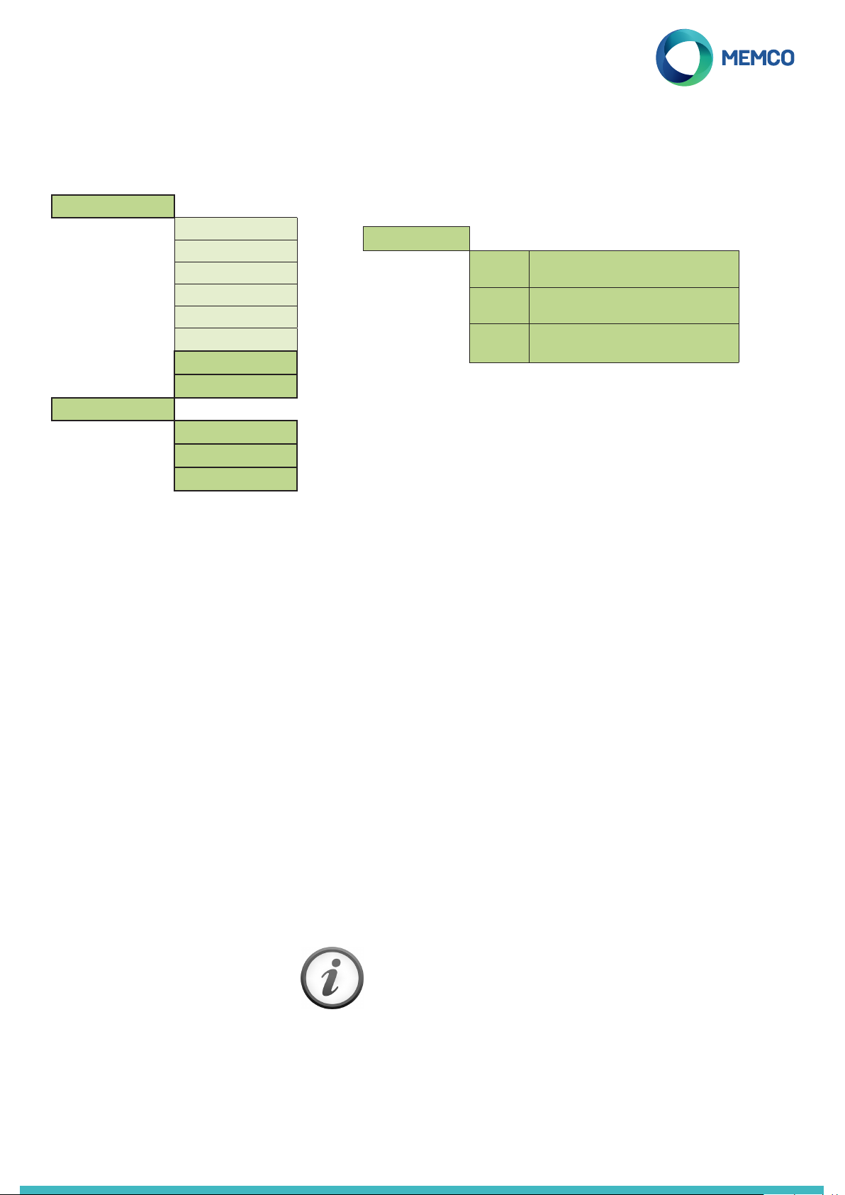
Relay Override
Relay Override >
GMT Oset
Will not need updating on the unit. For reference only.
Templates
The current programming selection on the C100 Programming
Tool (C100 PT) can be saved as a template to allow ‘One Touch
Programming’.
Up to eight programming templates can be stored on the C100 PT.
None The relay will switch according to the Relay Mode
setting.
Open The relay contacts will be held in the open state
until Relay Override is changed again.
Closed The relay contacts will be held in the closed state
until Relay Override is changed again.
5. Overwrite an existing template with the current programming
selection on the C100 PT:
6. Select the template you whist to overwrite form the list and
press ü
7. In the conrmation screen press ü to load the template or
press û to cancel
Del. Template
1. Delete a template from the C100 PT:
2. Select the required programming template from the list and
press ü
3. If no templates are saved to the C100 PT then the list will be
blank
4. In the conrmation screen press ü to load the template or
press û to cancel.
If you require any further assistance when
programming the C100 unit, please call our
Technical Service Team on:- 01628 540160.
Page 12

Call Centre Operator Instructions
What to do when receiving an alarm call...
1. When you answer the call you will hear an automated message informing you that the call is a lift alarm; you will then
be given two options:
+ Listen to the message detailign the location of the trapping (press 3)
+ Be placed into two-way communication with the lift car (press #)
2. If you need to hear the lift location again, press 3 on your telephone keypad at any time
3. After talking to the passengers for 2 mins and 30 secs, you will hear a prompt message informing you that you
have 30 secs remaining. Press # to extend the call
4. To end the call press * then #
What to do when dialling into a lift...
1. Dial the C100/Lift Telephone Number
2. You will hear a recorded location message followed by ‘beeps’ or (if no location message has been recorded)
just ‘beeps’. Press # after the ‘beeps’ for two-way communication with trapped passengers
3. If you need to hear the lift location again, press 3 on your telephone keypad at any time
4. After talking to the passengers for 2 mins and 30 secs, you will hear a prompt message; you have 30 secs
remaining
5. To end the call press * then #
Memco is a brand of Avire
Avire Global Ptd Ltd
Unit 1, The Switchback
Gardner Road
Maidenhead
Berkshire SL6 7RJ, UK
C100 858 IG V04 (GB)_AG 24/08/2017
 Loading...