

Meltric SP Instruction Manual
L1 L2 L3 N
L1 L2 L3 N
P1 P2
A
COMPANY OF MARECHAL ELECTRIC
WARNING
ENGLISH OPERATING INSTRUCTIONS
SP
INSTALLATION
SP devices should be installed by qualified
electricians in accordance with all applicable
local and national electrical codes.
Before installing, verify the power is off and the product
ratings are appropriate for the application. Ensure the
conductors meet code requirements and are within the
wiring terminal capacities noted in Table 3.
Table 3 - Wiring Terminal Capacity
Main Contacts Aux. Contacts
Max Min
SP 777 MCM 2/0 12-14 AWG
NOTICE: To avoid transmitting torque to the device
moldings when securing the lugs, hold the terminal in
place with a 24 mm wrench (flats are provided).
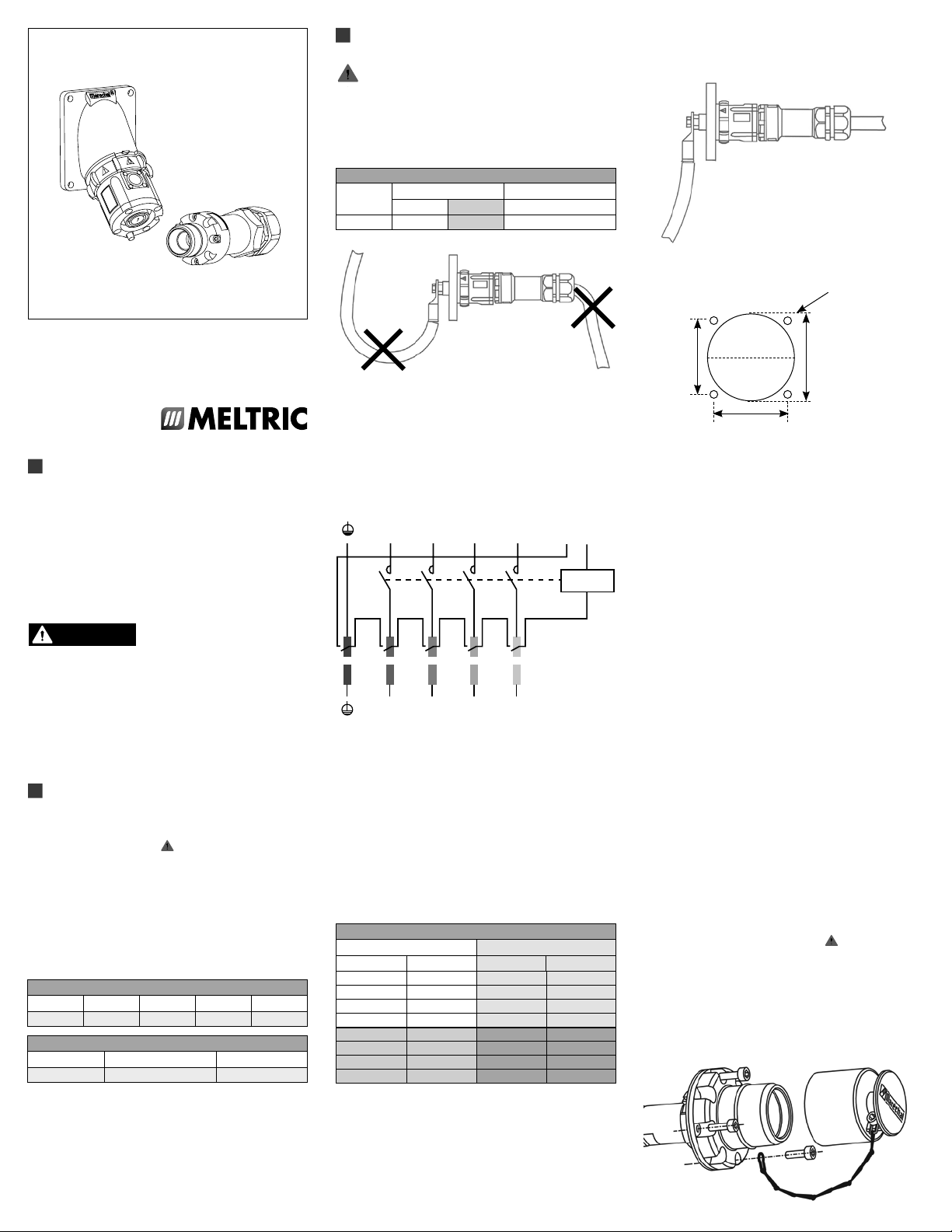
Hole Pattern for Custom Mounting
Ø.201 thru or
tap for 10-32
©2020 MELTRIC Corporation. All rights reserved.
INSSP G
A manufacturer of products using Marechal technology
GENERAL
SP devices are single-pole, high-amperage plugs and
receptacles that are designed for safety, durability, and
ease of operation. Each device is mechanically interlocked
with an integral pilot circuit switch for controlling the
power circuit in order to prevent connection and
disconnection under load. Each of the phases as well
as the neutral and ground, are color coded and keyed to
prevent improper connection. SP receptacles are IP 2X
rated to prevent accidental finger contact with live parts.
There are inherent dangers
products. Failure to follow safety precautions can
result in serious injury or death. These instructions
must be followed to ensure the safe and proper installation,
operation and maintenance of the MELTRIC devices.
Before installation, disconnect all sources of power to
the circuit to eliminate the risk of electrical shock. This
product must be installed with an electrical interlock
that prevents connection or disconnection in a loaded
condition.
RATINGS
The SP series is CSA listed for use in Non-Load Break
applications up to 600A at 600VAC, 500 HP 3 phase
at 480 VAC and 600 VAC. The SP devices are NOT
designed or listed for current interruption. The SP
receptacle is provided with two auxiliary/pilot contacts
that make (close) when the locking collar is rotated after
plug insertion. The pilot contacts are designed for use
in control circuit wiring of medium current switchgear,
(see diagram of pilot circuit wiring). The SP pilots have
a D300 rating as shown in Table 1. The phase contact
is rated to withstand a 30 kA short circuit with a current
limiting fuse rating as shown in Table 2.
Table 1 - Auxiliary Contact Ratings
Device 120VAC 240VAC 480VAC 600VAC
SP .6A .3A
Table 2 - Short Circuit Withstand Ratings
Device Rating Fuse Type
SP – 600A 30 kA @ 600 VAC Class L 1400A
1 - Short Circuit Rating applies with fusing up to this amperage.
Ratings are based on tests performed with Mersen non-time Delay
Current Limiting fuses.
2 - Tests performed with maximum allowable motor fusing sized
per the 2008 NEC.
associated with electrical
- -
1
2
NOTICE: Ensure the plug and its flexible cable do not
exert a significant force or a constraint on the receptacle.
Wiring of the pilot contacts
The SP auxiliary/pilot contact leads of each device
should be wired in series within the power control
circuit. A typical pilot circuit wiring diagram is
shown below.
L1 L2 L3 N
L1 L2 L3 N
Wiring of the main conductor
Use a flexible cable between 2/0 and 777 MCM (70
and 400 mm2). See Table 4 for recommended conductor
strip lengths. Threaded lugs have integral threads that
screw into the terminals. The threaded lug should be
tightened until the tapered section is secured in solid
contact with the terminal. Crimped lugs are secured
with M12 bolts that should be tightened to approximately
30 ft-lb (40 N.m.) with a 3/4" (19 mm) wrench. Apply
a torque of 30ft-lbs (40 N.m.) to the lugs with a 3/4”
(19mm) wrench. A 6 ton dieless crimper is recommended
for crimping of the lugs. On the threaded lugs do not
crimp past the line.
Table 4 - Recommended Strip Length
Wire Size Strip Length
2
mm
70 2/0 29 1.14
95 3/0 32 1.25
120 4/0 / 250 35 1.38
150 300 38 1.58
185 350 43 1.69
240 450/500 47 1.85
300 600 50 1.97
400 700/777 59 3.32
AWG mm
2
P1 P2
in
2"1.67"
1.67"
NOTICE: In order to maintain IP66/IP67 protection in
custom installations, watertight seals must be used
under the heads of the four mounting bolts and they
must be retained by a lock washer and nut on the
inside of the box or panel. Alternatively, four blind holes
can be drilled and threaded to accommodate #8-32 x
5/8" mounting screws. The hole depth must be sufficient
to achieve adequate gasket compression.
Achieving rated watertightness
Rated IP66/IP67 watertightness to is achieved when
the plug and receptacle are mated. When disconnected,
the receptacle cap must be fully inserted with the slot
in the cap aligned with the protruding ‘button’. The
plug cap must be pressed firmly into place.
NOTICE: Proper steps must be taken to maintain
watertightness at threaded connections on the plug
handles or at the junction box. The use of a sealer
tape is recommended.
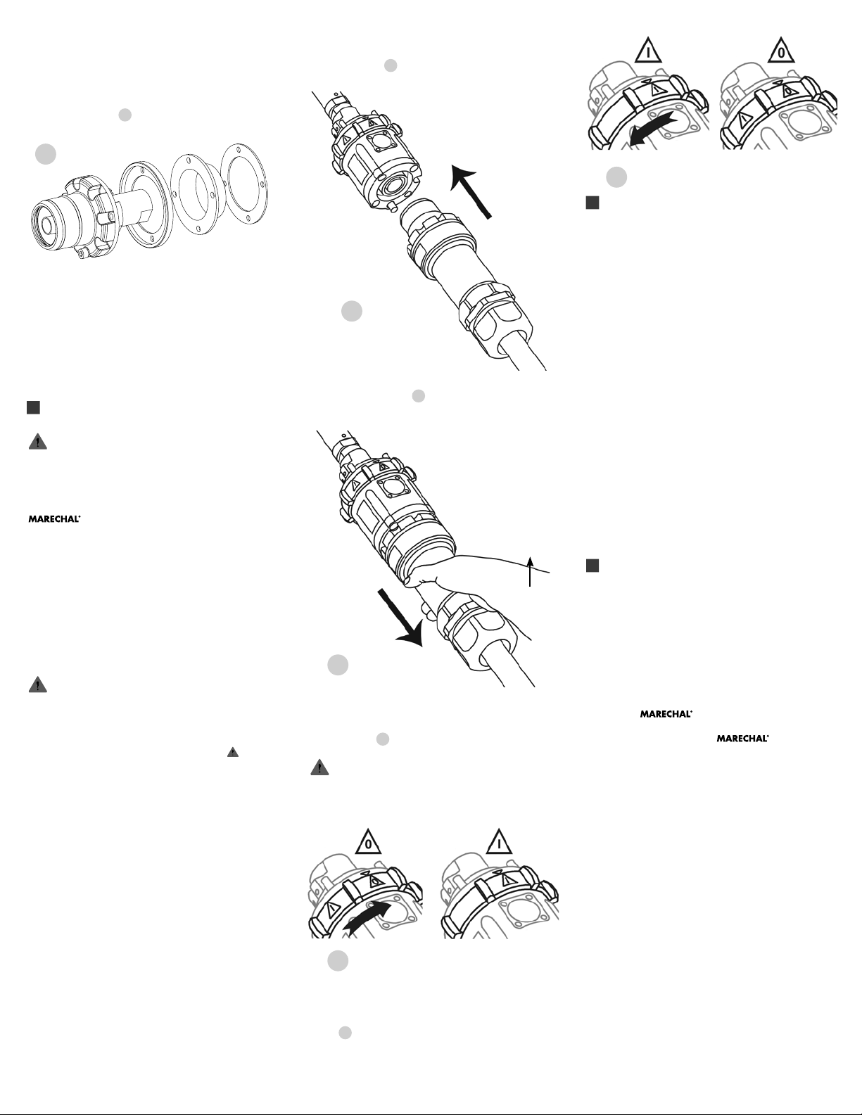
Attaching the handle
Insert cable through cable gland and handle before
tightening the phase conductor. Assemble handle with
the screws and gasket supplied, (use short screws for
inlets, long screws for receptacles) and tighten cable
gland with an appropriate tool.
NOTICE: MELTRIC threaded lugs are required for use
with handles.
Attaching the metal angle (if required)
Attach receptacle or inlet to metal angle using the
screws and gasket supplied, (use short screws for
inlets, long screws for receptacles). Connect the
metal angle to ground. Apply a torque of 17 in-lbs
(2 N.m.) to each screw.
Assembly of the plug/inlet cap
Attach the cap to the plug/inlet by retaining the end of
the chain under one of the mounting screws.
Gasket
Connection
In order to achieve rated watertightness, the flat black
gasket must be installed between the inlet or receptacle
and the panel or accessory to which itis attached.
When assembling the inlet or receptacle to the side of
an enclosure, the isolating ring must be positioned as
indicated on Figure 1.
1
A: Color-coded ring
B: Isolating ring
C: Flat color-coded gasket
Rated current and voltage markings
It is essential to indicate the current and voltage of the
main circuit on the supplied stickers. Apply the stickers
on or adjacent to the product so they can easily be seen.
OPERATION
To ensure safe and reliable operation, MELTRIC
plugs and receptacles must be used in accordance
with their assigned ratings.
SP devices can only be used in conjunction with mating
receptacles or plugs manufactured by MELTRIC or
another licensed producer of products bearing the
NOTICE: Do not attempt to operate the SP device until
the receptacle is mounted. The mounting bolts must
be in place to maintain alignment of components and
compression against the panel or handle is required to
maintain assembly.
SP series plugs and receptacles feature different
mechanical keying of L1, L2, L3, N, and G. Mating
plug/receptacle combinations are color coded for easy
identification.
The pilot circuit can only be turned ‘on’ when the
plug is engaged and the plug can only be removed
when the pilot curcuit is in the ‘off’ position. For
safety, MELTRIC recommends the following connection
sequence: Ground, Neutral, Phase 1, Phase 2, Phase 3.
technology trademark.
SP series plugs and receptacles are not intended to
be connected or disconnected under load. The pilot
circuit must be used to control the power circuit.
A
B
C
Insert the plug straight into the receptacle until a ‘click’
is heard. Figure 2 The plug and its flexible cable
must not exert force on the receptacle.
2
Pull on the plug to make sure it is properly latched in
the receptacle. Figure 3. A small rotation of the plug,
in either direction, engages the locking finger on the
receptacle to prevent any further rotation.
3
To close the pilot circuit and mechanically lock the plug
into the receptacle, turn the ring on the receptacle until
the “1” lines up with the arrow across from the release
button. Figure 4.
Do not attempt to turn the ring towards “1”
when there is no plug engaged. Defeating the
mechanical lock could create a potentially hazardous
condition if energized under load.
Latch
Release
Button
5
MAINTENANCE
WARNING: Before inspecting, repairing, or maintaining
MELTRIC products, disconnect electrical power to the
receptacle to eliminate the risk of electrical shock.
MELTRIC products require little on-going maintenance.
However, it is a good practice to periodically perform
the following general inspections:
• Check the mounting screws for tightness.
• Verify that the weight of the cable is supported
by the strain relief mechanism and not by the
terminal connections.
• Check the IP gaskets for wear and resiliency.
Replace as required.
• Verify the electrical continuity of the ground
circuit.
• Check the contact surfaces for cleanliness
and pitting.
Use a clean cloth to rub off deposits of dust or similar
foreign materials on the contacts and the plug interiors.
Sprays should not be used, as they tend to collect dirt.
If any significant pitting of the contacts or other serious
damage is observed, the device should be replaced.
MANUFACTURER’S RESPONSIBILITY
MELTRIC’s responsibility is strictly limited to the repair
or replacement of any product that does not conform
to the warranty specified in the purchase contract.
MELTRIC shall not be liable for any penalties or
consequential damages associated with the loss of
production, work, profit, or any other kind of financial
loss incurred by the customer.
MELTRIC Corporation shall not be held liable when
its products are used in conjunction with products not
bearing the
of MELTRIC products in conjunction with mating devices
that are not marked with the
trademark shall void all warranties on the product. For
the latest revision of our documents, visit meltric.com.
MELTRIC Corporation is an ISO 9001 certified company.
Its products are designed, manufactured and rated in
accordance with applicable UL, CSA and IEC standards.
MELTRIC designs and manufactures its products in
accordance with Marechal keying standards established
to ensure intermatablility with similarly rated products
manufactured by Marechal Electric Group.
technology trademark. The use
technology
4
Disconnection
To open the pilot circuit and unlock the plug, turn the
ring back until the “0” is aligned with the arrow.
Figure 5. This action signals the controller to switch
off the power and unlocks the plug. To remove the
plug, press firmly on the latch release button and
simultaneously pull on the plug. A slight rotation of
the plug may be required before it can be removed.
INSSP G
 Loading...