

OPERATING INSTRUCTIONS
WARNING
PXN12c
DXN25c
DXN37c
INSPXNDXNMULTI E
Meltric Corporation / 4640 Ironwood Drive Franklin, WI 53132
el. : 800 433 7642 / Fax : 414 817 6161 / e-mail : mail@meltric.com
T
manufacturer of products using M arechal technology
A
eltric.com
m
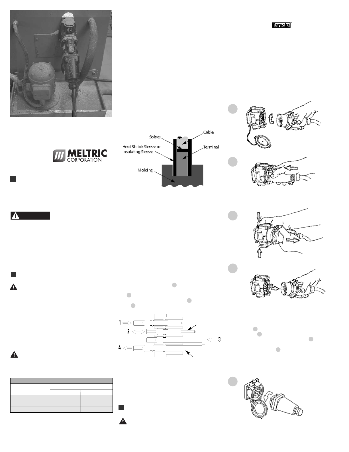
. Contacts can be soldered or crimped. If
1
rimping, crimp the contact with a KNIPEX
c
rimping tool part # 61-CA500 or a GREENLEE
c
rimping tool part # 45505. Use the 4 mm
c
footprint whatever the conductor cross-section.
erform a double crimping with a 90° rotation, in
P
ompliance with IEN 60352-2.
c
. Prior to soldering or crimping a heat shrink
2
sleeve (supplied- part # 9CP0250) must be
lipped over each conductor or alternatively an
s
insulating sleeve (supplied - part # 9SES201007301)
an be used but the insulating sleeve must be
c
nstalled using sleeve tool 61-CA500 (sold
i
separately).
. If soldering use tin solder and a 50 W soldering
3
iron. Insert the conductor in the terminal and
eat the terminal for about 30 s. During heating,
h
insert the solder wire in the hole at the foot of the
erminal and let the solder penetrate by capillary
t
ction. Let the terminal cool without any tension
a
on the conductor.
2
eltric plugs & receptacles can only be used in
M
onjunction with mating receptacles or plugs
c
anufactured by Meltric or another licensed producer
m
f products bearing the
o
trademark. WARNING: PXN12c/DXN25c/DXN37c
lugs and receptacles must be operated in
p
ompliance with its explosion-proof classifications.
c
hen not in use, the receptacle is shielded by a
W
protective lid preventing the entry of dust and
oisture.
m
his is held in the closed position by one or two
T
atch(es). To release the spring-loaded lid, depress
l
the latch(es).
DXN25c/DXN37c
TM
echnology
t
1
2
GENERAL
PXN12c/DXN25c/DXN37c plugs and receptacles
comply with international and European safety rules
and particularly with ATEX 94/9/CE Directive.
PXN12c/DXN25c/DXN37c products can be used in
zones 1, 2 (Gas), and 21, 22 (Dust).
There are inherent dangers
products. Failure to follow safety precautions can
result in serious injury or death. These instructions
must be followed to ensure the safe and proper
installation, operation and maintenance of the Meltric
devices. Before installation, disconnect all sources of
power to the circuit to eliminate the risk of electrical
shock. It is imperative that Meltric explosion-proof
multicontact plugs and receptacles are connected or
disconnected without a load in a de-energized state.
INSTALLATION
PXN12c/DXN25c/DXN37c plugs and
receptacles must be used in conjunction with
other appropriately rated hazardous duty
products and must be installed by qualified
electricians in accordance with all applicable
local and national electrical codes.
Assembly
Optimum operating conditions are achieved by
installing PXN12c/DXN25c/DXN37c plugs and
receptacles with the latch at the top.
Wiring
Before starting, verify that the power is off, that
the product ratings are appropriate for the
application, and the conductors meet code
requirements and are within the capacities of
the terminals noted in Table 1.
Table 1 — Wiring Terminal Capacity* (in AWG)
Device Min Max
DXN25c 16 14
DXN37c 16 14
PXN12c 16 14
The maximum cross-section of the conductors is
4934 CM (2.5 mm
must be stripped by .315 in (8 mm).
associated with electrical
Contacts
2
) (solid or flexible). Conductors
4. Slip the heat shrink or insulating sleeve over the
whole visible part of the contact, down to the molding.
5. Slide the heat-shrink sleeve up to the shoulder of
the contact. With a heat gun, apply heat evenly
370° around the sleeve until it shrinks around the
terminal and wire.
NOTICE: For a proper clamping, the use of PVC
cables is not recommended.
WARNING: This product must be electrically
grounded to Earth. A grounding terminal is provided
on all metal accessories.
Contact Assembly/Disassembly
Once wired, contacts must be inserted through the
rear of the interior moulding 1. Push each contact
fully home. Check its proper engagement by a light
pull 2. Contacts can be removed with the supplied
tool: insert the tool through the front 3 and push fully
home 4. Tool part # 9-LD12-37.
Contact
Tool
Contact Configurations
This is in reference to different keying positions on the
PXN12c. If or when 2 contacts are not in use, 9
different contact/keying configurations can be achieved
by plugging the contact holes not in use with the hole
plugs supplied.
OPERATION
To ensure safe and reliable operation, Meltric
plugs and receptacles must be used in
accordance with their assigned ratings.
3
4
To connect, align the plug bayonets with the hollow
part of the receptacle. Insert the plug and turn until
the stop. The plug is in the rest position, circuit is
open, figure 1. Push the plug fully home until
latched, figure 2. To disconnect, depress the latch.
The plug returns to its rest position, figure 3. Turn
the plug in the opposite direction to remove it. Shut
the receptacle lid, figure 4.
PXN12c
5
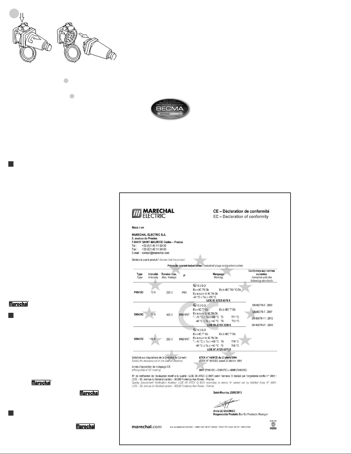
6
o connect, align the plug bayonets with the hollow
T
arts of the receptacle (if any, use the two red marks
p
as a visual indication), figure 5. Push the plug in and
urn counter-clockwise; the circuit is closed figure 6.
t
o disconnect, press the latch, push the plug and turn
T
it clockwise to withdraw it figure 6. Close the lid.
ockout Provisions
L
ARNING: It is imperative to lock out PXN12c/
W
DXN25c/DXN37c plugs and receptacles after
connection or disconnection.
A mechanical locking device on receptacle latches, by
means of either a padlock(s) or by a specific screw
revents any accidental disconnection under load.
p
AINTENANCE
M
WARNING: Before inspecting, repairing, or main-
taining Meltric products, disconnect electrical power
to the receptacle to eliminate the risk of electrical shock.
Rules applying to products for use in explosive
atmospheres require that any replacement of
components must be performed under the control of
the manufacturer: Meltric Corporation.
irectives, and particularly of the European ATEX
d
irective. They bear the CE marking whenever
D
pplicable. They also bear the markings of their
a
xplosion-proof classification.
e
eltric Corporation is an ISO 9001 certified company.
M
Its products are designed, manufactured and rated in
ccordance with applicable UL, CSA and IEC
a
standards. Meltric is also a member of BECMA, the
nternational Butt-contact Electrical Connectors
i
anufacturers’ Association. Like all members, Meltric
M
M
T
additionally designs and manufactures its products in
ccordance with BECMA standards established to
a
nsure intermatablility with similarly rated products
e
manufactured by other members.
From time to time, the fastening screws should be
checked for tightness. Care should be taken that the
weight of the cable is taken by the glanding
arrangement and not the terminals themselves.
Contact surfaces may be checked for cleanliness.
Any deposit of dust can be rubbed off with a clean
cloth. Sprays should not be used, as they tend to
collect dirt. Depending on prevailing conditions, the
pitting of plug and socket contacts should be regularly
monitored. In the event of serious damage, contact
your supplier to have the contacts replaced.
IP gaskets between plug and receptacled bodies
should be inspected periodically.
Any repair or service must be achieved with genuine
parts only.
MANUFACTURER’S RESPONSIBILITY
Meltric’s responsibility is strictly limited to the repair or
replacement of any product that does not conform to
the warranty specified in the purchase contract.
Meltric shall not be liable for any penalties or
consequential damages associated with the loss of
production, work, profit, or any other kind of financial
loss incurred by the customer.
Meltric Corporation shall not be held liable when its
products are used in conjunction with products not
bearing the
use of Meltric products in conjunction with mating
devices that are not marked with the
TM
technology trademark. The
TM
technology trademark shall void all warranties on the
product.
DECLARATION OF CONFORMITY
PXN12c/DXN25c/DXN37c use the
TM
technology. They have been designed, manufactured
and controlled in a strict respect of the relevant
international and European standards, laws and
INSPXNDXNMULTI E
 Loading...