

Meltric PN12c, DSN12c, DS24c, DSN24c, DS37c Instruction Manual
...
A
COMPANY OF MARECHAL ELECTRIC
WARNING
ENGLISH OPERATING INSTRUCTIONS
PN12c/DSN12c
DS24c/DSN24c
DS37c/DSN37c
©2020 MELTRIC Corporation. All rights reserved.
A manufacturer of products using Marechal technology
GENERAL
PN, DS and DSN Multipin products are used for power
and control. They can carry loads as well as low level
signals and information. These multipin devices comply
with applicable IEC standards.
Please follow the instructions below to ensure the proper
installation, operation and maintenance of this product.
There are inherent dangers
products. Failure to follow safety precautions can result in
serious injury or death. These instructions must be followed
to ensure the safe and proper installation, operation and
maintenance of the MELTRIC devices. Before installation,
disconnect all sources of power to the circuit to eliminate
the risk of electrical shock.
INSTALLATION
PN, DS and DSN Multipins should be installed by
qualified electricians in accordance with all applicable
local and national electrical codes.
Before starting, verify that the power is off, that the product
ratings are appropriate for the application, and that the
conductors meet code requirements and are within the
capacities of the terminals noted in Table 1.
General Notes & Precautions
Table 1 - Wiring Terminal Capacity1 (in AWG)
Device Minimum Maximum
PN12c 18 14
DSN12c 18 14
DSN24c 18 14
DSN37c 18 14
DS24c 18 14
DS37c 18 14
1
Capacity is based on THHN wire sizes
1. Self-tapping screws are provided for use with
some polymeric accessories. High torque may be
required to drive them in. NOTICE: Once they
are seated, care should be taken in order to avoid
over-tightening them against the plastic material.
2. Various handles and cord grip options may be
used. These instructions are based on handles
provided with integral multi-layer bushing cord grips.
3. NOTICE: MELTRIC threaded handles come with
tapered style threads. The use of fitting seal tape
is required to maintain watertightness of all
NPT fittings and joints.
associated with electrical
Main Contacts
INSPNDSDSNMULTI A
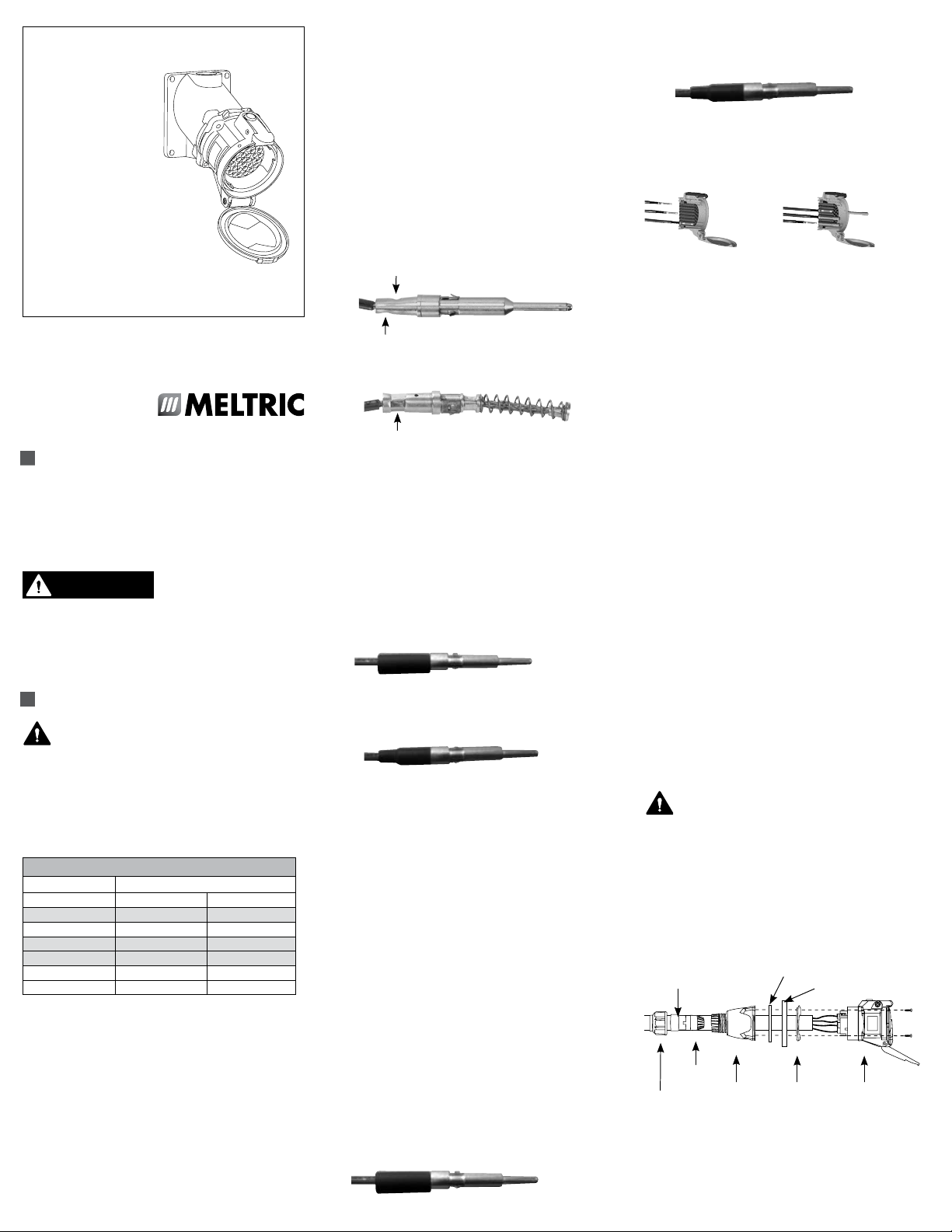
Crimped/Soldered Terminal Wire Connections:
For 18 AWG and 16 AWG wire, the use of ferrules is
required:
1. Strip each conductor to 25/64-inches (10-mm).
2. Insert ferrule into contact. For 16 AWG wire, use
ferrules marked MEC7177071. For 18 AWG wire
insert ferrule 22170-13 into ferrule MEC7177071.
3. Insert stripped wire end into ferrule.
(Perform either step 4 or 5)
4. For Crimping the Contacts, use either North
American Contact Crimping Tool 4CN30 (using
crimping slot 12-10) or Crimp contact with
European Contact Crimping Tool 61-CA500
(using 4 MM slot).
*With 4CN30 - Double crimp, once near the
terminal opening and a second crimp slightly
above the first, rotated 180 degrees.
*With 61-CA500 - Double crimp, once near the
terminal opening and a second time at the same
location, rotated 90 degrees.
5. NOTICE: Soldering of the wire into the contact
must be performed with the contact out
of the Interior Insulator to prevent damage
to the insulator.
• Using tin solder and a 50W soldering iron, heat
the terminal for approximately 30 seconds.
While heating, apply the soldering wire into the
hole at the bottom of the terminal and let it
penetrate by capillary action. Let it cool down
without any mechanical stress.
6. Slide the Heat Shrink Insulation Sleeve over the
contact until it butts up against the contact
shoulder. NOTICE: Sleeve must be applied to
maintain creepage and clearance distance.
Please see picture.
7. With a Heat Gun that has a temperature range
of 600°F to 950°F, apply heat evenly 360°
around the sleeve until it shrinks around the
contact and wire.
For 14 AWG Wires (Max), the Ferrule is not required:
1. Strip each conductor to 25/64-inches (10-mm).
2. Insert wire into contact.
(Perform either step 3 or 4)
3. For Crimping the Contacts, use either North
American Contact Crimping Tool 4CN30 (using
crimping slot 8) or Crimp contact with European
Contact Crimping Tool 61-CA500 (using 4 MM slot).
*With 4CN30 - Double crimp, once near the
terminal opening and a second crimp slightly
above the first, rotated 180 degrees.
*With 61-CA500 - Double crimp, once near the
terminal opening and a second time at the same
location, rotated 90 degrees.
4. NOTICE: Soldering of the wire into the contact,
must be performed with the contact out of the
Interior Insulator to prevent damage to the insulator.
• Using tin solder and a 50W soldering iron, heat
the terminal for approximately 30 seconds.
While heating, apply the soldering wire into the
hole at the bottom of the terminal and let it
penetrate by capillary action. Let it cool down
without any mechanical stress.
5. Slide the Heat Shrink Insulation Sleeve over the
contact until it butts up against the contact
shoulder. NOTICE: Sleeve must be applied to
maintain creepage and clearance distance.
Please see picture.
6. With a Heat Gun that has a temperature range
of 600°F to 950°F, apply heat evenly 360°
around the sleeve until it shrinks around the
contact and wire.
Assembly of Contacts
Once wired, the contacts must be inserted into the rear
of their respective insulating block. The rear side of the
inlet/plug or receptacle/connector is considered as the flat
surface of the 4-bolt hole mounting surface.
Assembly Disassembly
1. NOTICE: Before insertion of a contact into an
insulator, please review the insulator’s contact
numbering scheme so the ground and each
contact (phase) is placed into the proper hole.
2. Push the wired contact into the insulating block
until it stops and snaps into place.
3. Ensure its correct mounting by slightly pulling on
the contact.
4. The male contacts are solid for their entire
length and are inserted with the contact tip first
into the rear of the inlet/plug.
5. The female contacts consist of a flexible braid
and spring and are inserted with the contact tip
first into the rear of the lidded receptacle/connector.
6. Insert the Provided Hole Plugs into the unused
holes in the front of each insulating block.
NOTICE: If a new Receptacle or Inlet is to mate
with a previously installed device, pay particular
attention to the number of contacts and numbered
position in the Receptacle or Inlet. Continuity will not
be obtained unless the male and female contacts are
appropriately mated.
Disassembly of Contacts
1. To remove the contact from the insulating block,
the provided Multi-Contact Removal Tool 61-CA593
must be used. From the front side of the insulating
block, slide the contact removal tool over the contact.
2. Push until the contact pops out the back side of
the insulating block.
3. NOTICE: Each contact is designed to be
removed from the insulating block a maximum
of 3 times. New contacts should be used if
contacts are removed more than 3 times.
Voltage Labels
Always have a qualified electrician complete the
installation and apply one of the supplied voltage
labels that best describe the voltage application level.
WARNING: For safety reasons, it is always recommended
to use a ground wire. Please reference
your local codes for specific electrical requirements.
Assembly for In-Line Connections (DS/DSN)
When DS and DSN Multipins are used as in-line connectors,
finger drawplates should be installed on both the receptacle
and plug in order for the user to more easily provide the
leverage required to connect the device.
Bushing
Strain
Relief
Compression
Nut
Assembly for In-Line Connections (All)
Adjust the bushing diameter to fit the cable by removing
inner sections of it as required. Insert the bushing into the
strain relief, then insert the assembly into the handle
Handle
Finger Drawplate Gasket
Finger Drawplate
Color-Coded
Gasket
Receptacle
(or Inlet)
and loosely install the compression nut. Insert the cable
WARNING
through the handle, the thin black drawplate gasket and
finger drawplate (if applicable) and the color coded gasket.
Strip the cable sheath to provide a workable wire length,
being mindful that the sheath must extend into the handle
to achieve a secure cord grip. Then strip the individual
wires to 25/64” and twist the strands of each conductor
together.
Verify that the cable sheath extends beyond the strain
relief and into the handle. Assemble the receptacle (or
inlet), the color coded gasket, the finger drawplate, and
the thin black drawplate gasket to the handle with the four
self-tapping screws provided.
Adjust the cable location so that it will not be under tension
inside the handle and tighten the compression nut to
secure the cable.
Assembly for Mounted Receptacles (or Inlets)
In applications where PN, DS and DSN receptacles (or
inlets) are mounted to wall boxes, panels or other equipment,
optimal operation is achieved when the device is installed
with the latch at the top. For DS receptacles, mount
device so one latch is at the top. Insert the cable or wires
through the wall box and cut to allow adequate length,
strip the cable sheath as desired, strip the individual
wires to 25/64”, and twist the strands of each conductor
together.
Assemble the receptacle (or inlet) and the color-coded gasket
to the box with the appropriate hardware. Assemble the
mating plug (or receptacle) to the cord end as indicated
in the assembly instructions above for in-line connections,
except there will be no finger drawplate or associated
black gasket.
Hole Pattern for Custom Mounting
In applications where custom mounting to a panel or box
is being performed, the clearance and mounting holes
should be drilled as indicated in the following diagram
and Table 2.
B
C
A
B
Table 2 - Custom Mounting Dimensions
‘A’ ‘B’ ‘C’
Model
Inches mm Inches mm Inches mm
PN12c 2 51 1.65 42 .19 5
DSN12c 2 51 1.65 42 .19 5
DSN24c 2.25 57 1.89 48 .19 5
DSN37c 2.50 64 2.17 55 .19 5
DS24c 2.25 57 1.89 48 .19 5
DS37c 2.50 64 2.17 55 .19 5
NOTICE: In order to maintain the NEMA 4X or
IP66/IP67 protection provided by PN/DSN models in custom
installations, watertight seals should be used under
the heads of the four mounting bolts and they must be
retained by a lock washer and nut on the inside of the
box or panel. Alternatively, four blind holes may be
drilled and threaded to accommodate the mounting screws,
provided that the hole depth is sufficient to achieve adequate
gasket compression.
OPERATION WARNING
To ensure safe and reliable operation MELTRIC
plugs and receptacles must be used in accordance
with their assigned ratings.
They can only be used in conjunction with mating receptacles
or plugs manufactured by MELTRIC or another licensed
producer of products bearing the
technology
trademark.
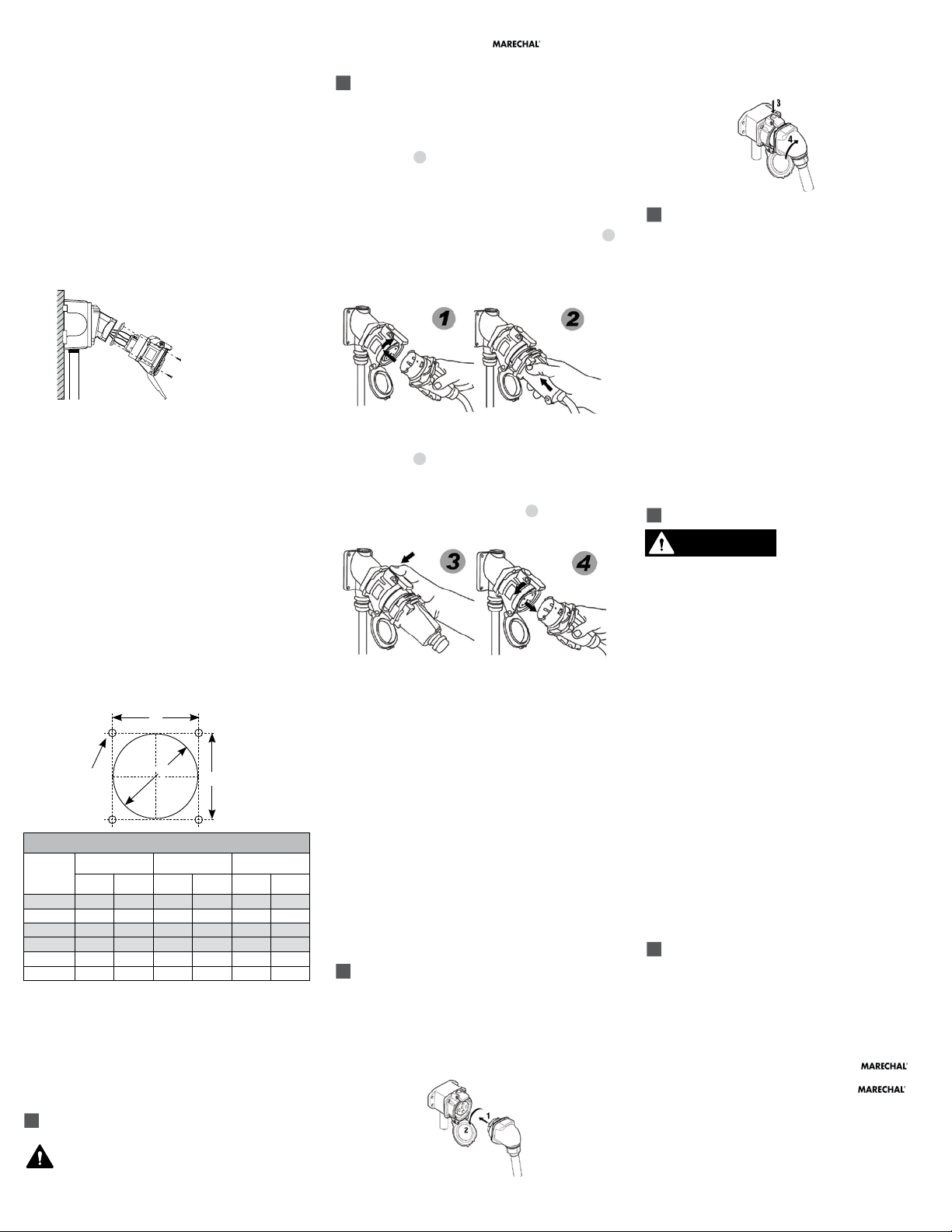
OPERATION (DS/DSN)
Connection
To connect a plug and receptacle, first depress the pawl
to open the lid on the receptacle, then orient the plug as
shown in figure 1 so that the red dot on the outside of
the casing lines up with the red dot just to the left of the
latch on the receptacle casing. Push the plug partially into
the receptacle until it hits a stop, then rotate the plug in
the clockwise direction until it hits another stop after about
30° of rotation. At this point, the circuit is still open. Push
the plug straight into the receptacle as shown in figure 2
until it becomes securely latched in place. The electrical
connection is now made. On in-line connectors, squeeze
the drawplates on both sides of the device together until
the plug latches in place.
Disconnection
To break the connection, simply depress the pawl as
shown in figure 3 . This will break the circuit and eject
the plug straight out to the rest, or off, position. The plug
contacts are de-energized at this point. To remove the
plug, rotate it counter-clockwise (about 30°) until it releases
from the receptacle as shown in figure 4 . Close and
latch the lid on the receptacle.
Connection and Disconnection of
Stainless Steel DS
Operation of the stainless steel DS is similar to the standard
DSN operation with the following two exceptions:
1. The stainless steel DS utilizes two pawls to
latch the plug to the receptacle. Thus to
disconnect the plug from the receptacle both
pawls must be depressed.
2. The stainless steel DS24c plug casing does not
have a red dot that can be used for proper
alignment before insertion. Instead, the thicker
groove in the plug casing should be aligned with
the thicker protruding screw in the receptacle
and the thinner groove should be aligned with
the thin protruding screw.
3. The stainless steel DSN37c casings do not
utilize red dots for alignment. For proper
alignment before insertion, align the arrow on
the plug with the “off” position on the receptacle.
OPERATION (PN)
Connection
To connect, open the protective plug cap, align the
red dots on the plug and receptacle bodies, insert plug
into receptacle, apply force and rotate the plug 20°
counterclockwise (CCW). The contacts will mate and the
circuit will close.
Disconnection
To open the circuit and remove the plug, press the pawl,
apply inward force and rotate the plug 20° clockwise
(CW). The plug can be safely withdrawn from the
receptacle. The plug contacts remain shrouded until after
the circuit is disconnected. Close protective plug cap to
prevent contamination by dirt, dust or other debris.
ACHIEVING RATED WATERTIGHTNESS
Rated ingress protection applies to the device when the
plug and receptacle are mated and latched together. It also
applies to the receptacle when the lid is latched closed.
NOTICE: MELTRIC threaded handles come with tapered
style threads. The use of fitting seal tape is required to
maintain watertightness of all NPT fittings and joints.
Lockout Provisions
PN and DSN receptacles may be purchased with optional
lockout provisions. To lockout the receptacle, close and
latch the lid and then attach the locking device through
the optional hole provided in the pawl. This will prevent
the lid from being opened for the insertion of a plug. This
feature is not available on SS devices.
NOTICE: Attaching the receptacle locking device with the
receptacle lid open will not prevent the insertion of a plug.
Lockout of the receptacle is only accomplished when the
lid is locked closed.
MAINTENANCE
Before inspecting, repairing,
or maintaining MELTRIC
products, disconnect electrical power to the receptacle to
eliminate the risk of electrical shock.
MELTRIC products require little on-going maintenance.
However, it is a good practice to periodically perform the
following general inspections:
• Check the mounting screws for tightness.
• Verify that the weight of the cable is supported
by the strain relief mechanism and not by the
terminal connections.
• Check the IP gaskets for wear and resiliency.
Replace as required.
• Verify the electrical continuity of the ground circuit.
• Check the contact surfaces for cleanliness and
pitting.
Receptacle contacts may be inspected by a qualified
electrician. This should only be done with the power off.
If any significant pitting of the contacts or other serious
damage is observed, the device should be replaced.
Deposits of dust or similar foreign materials can be
rubbed off the contacts with a clean cloth. MELTRIC
recommends regular cleaning of contacts in low voltage
applications. If a cleaning spray is used, it should be a
fast evaporating, non-conductive type that doesn’t leave
a residue and is compatible with plastics.
MANUFACTURER’S RESPONSIBILITY
MELTRIC’s responsibility is strictly limited to the repair or
replacement of any product that does not conform to the warranty
specied in the purchase contract. MELTRIC shall not be liable
for any penalties or consequential damages associated with the
loss of production, work, prot or any nancial loss incurred by
the customer.
MELTRIC Corporation shall not be held liable when its products are
used in conjunction with products not bearing the
technology trademark. The use of MELTRIC products in conjunction
with mating devices that are not marked with the
technology trademark shall void all warranties on the product.
MELTRIC Corporation is an ISO 9001 certied company. Its
products are designed, manufactured and rated in accordance with
applicable UL, CSA and IEC standards. MELTRIC designs and
manufactures its products in accordance with Marechal keying
standards established to ensure intermateablility with sim ilarly rated
products manufactured by Marechal Electric Group.
INSPNDSDSNMULTI A
 Loading...