

Meltric INDUSTRIAL PLUGS & RECEPTACLES Catalog
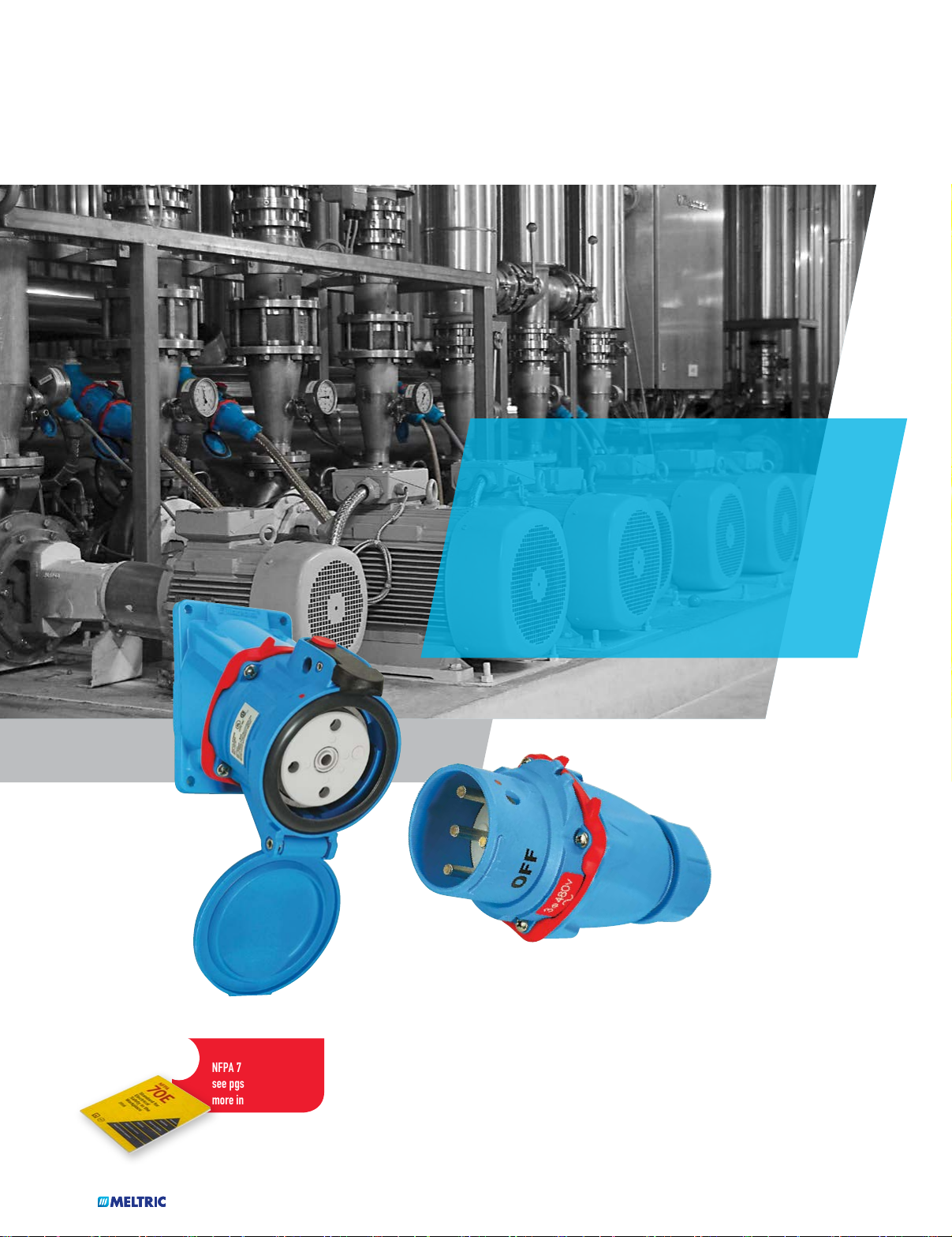
PRODUCT CATALOG
INDUSTRIAL PLUGS & RECEPTACLES
• SWITCH-RATED PLUGS & RECEPTACLES
• HAZARDOUS LOCATION PLUGS & RECEPTACLES
• CUSTOM POWER DISTRIBUTION PANELS
• HIGH AMPERAGE CONNECTORS
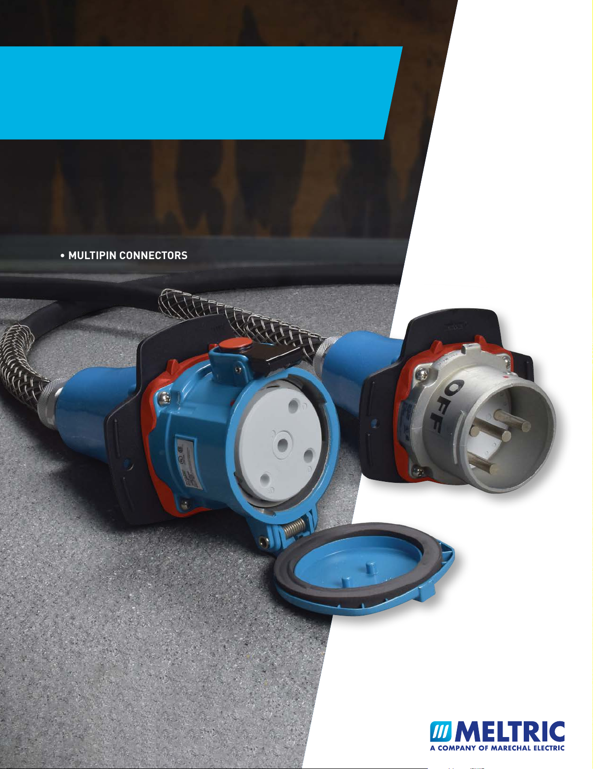
• MULTIPIN CONNECTORS
meltric.com

INDUSTRIAL PLUGS & RECEPTACLES
• Introduction
MELTRIC Overview pg 3
Product Features & Benefits pg 5
Product Summary & Selection Guide pg 9
Part Number & Ordering Guide pg 15
• Switch-Rated Plugs & Receptacles
The Main Differences pg 17
Selection Guide pg 21
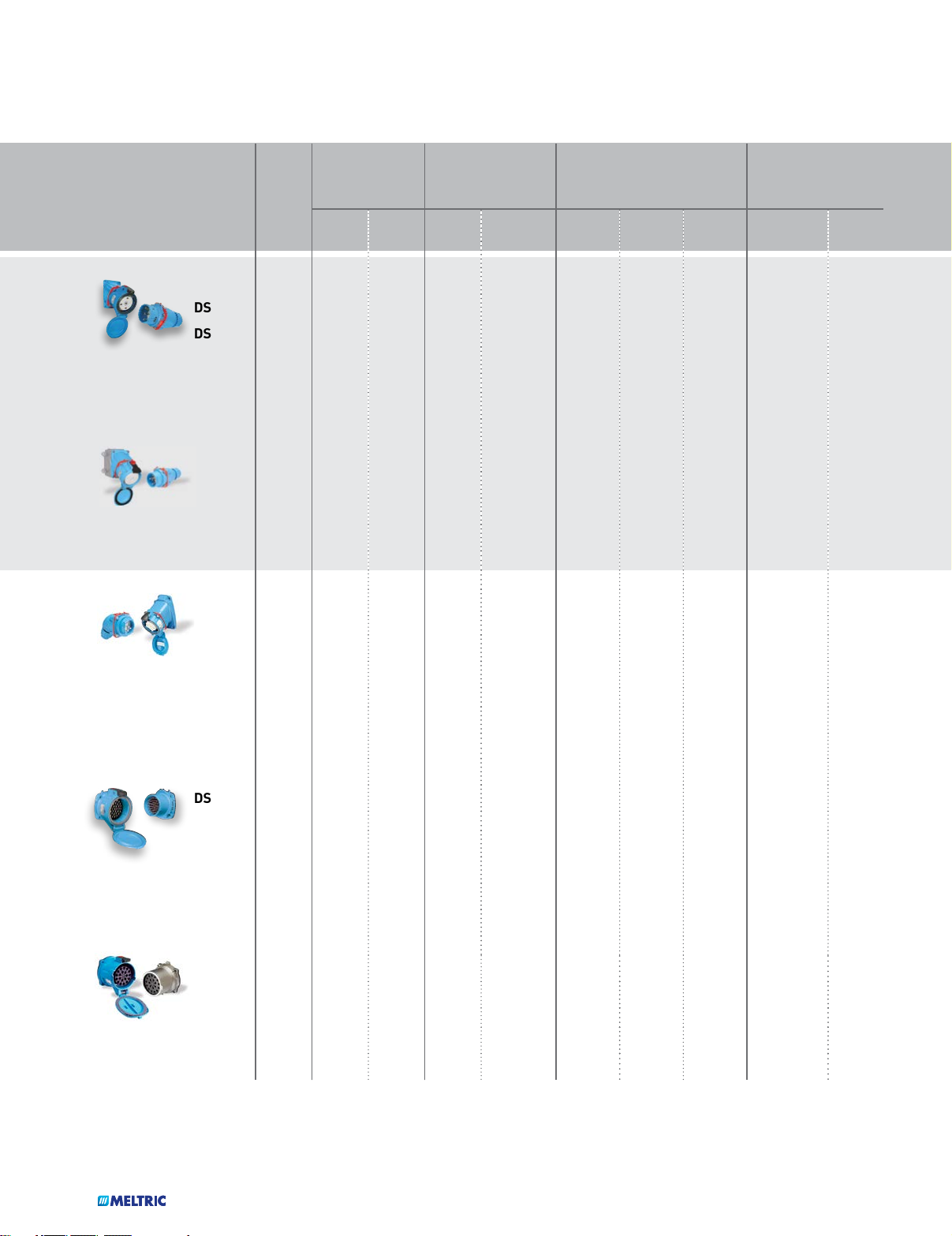
DSN
Type 4X/IP69/IP69K rated, metal or poly casings. From 20 – 150 A (1/2 – 75 hp) pg 25
DS
Type 3R rated, metal or poly casings. From 20 – 200 A (3/4 – 100 hp) pg 39
• Multipin Plugs & Receptacles
Multipin
4 – 37 pin connectors in poly and metal. From 2 – 50 A pg 57
• Standard Duty Plugs & Receptacles
DR
Type 3R rated, poly or metal casings. From 30 – 400 A pg 81
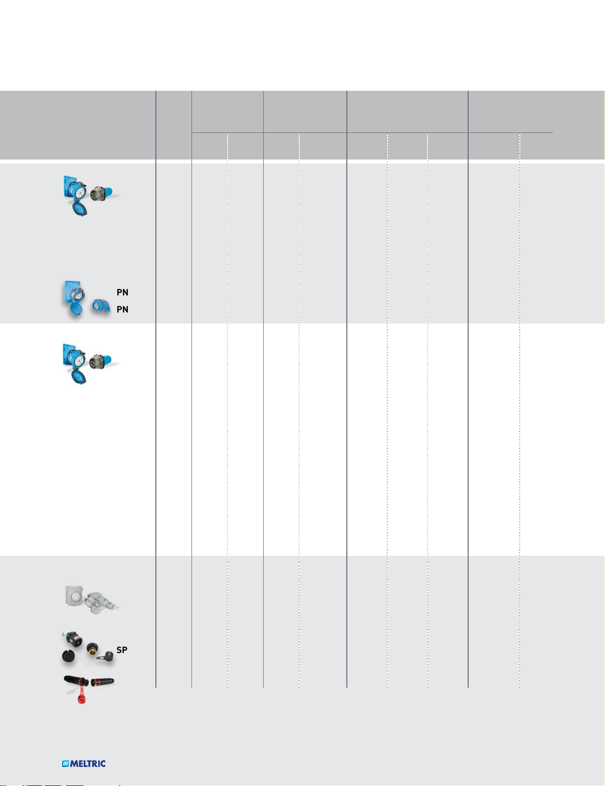
PN
IP66/IP67 rated or IP55 rated, poly or metal. 20 A pg 101
High Temp
For environments up to 465°F (240°C) pg 109
• Direct Current Plugs & Receptacles
DSDC
DC current rated, poly or metal casings. From 20 - 200 A (up to 750 VDC) pg 113
• High Ampacity Plugs & Receptacles
PF/PFQ
IP66/IP67 rated, metal construction. From 300 – 600 A pg 119
DR400
Type 3R rated, metal casings. 400 A pg 127
SP
Single pole, connectors up to 600 A pg 131
CS1000
Single pole, connectors up to 400 A pg 135
1
• Power Distribution
Custom Power Distribution Solutions
Built specifically to meet customer needs pg 141
Integral Circuit Protection Wall Boxes
Premounted receptacles wired to circuit protection 20 - 60 A pg 147
GFCI Combinations
Premounted receptacles wired to GFCI boxes 20 - 100 A pg 155
Safety Switch/Receptacle Combinations
Switch-rated receptacles mounted to single throw, fusible safety switch pg 157
• Specialty Products
WS – Welding Connectors
Single pole connectors (max 50 VAC) pg 161
Adapter Plates
For converting existing receptacles to MELTRIC pg 162
Cord Grips pg 165
Voltage/Phase Rotation Meter Assemblies pg 167
• Hazardous Location Plugs & Receptacles
Hazardous Duty Selection Guide pg 169
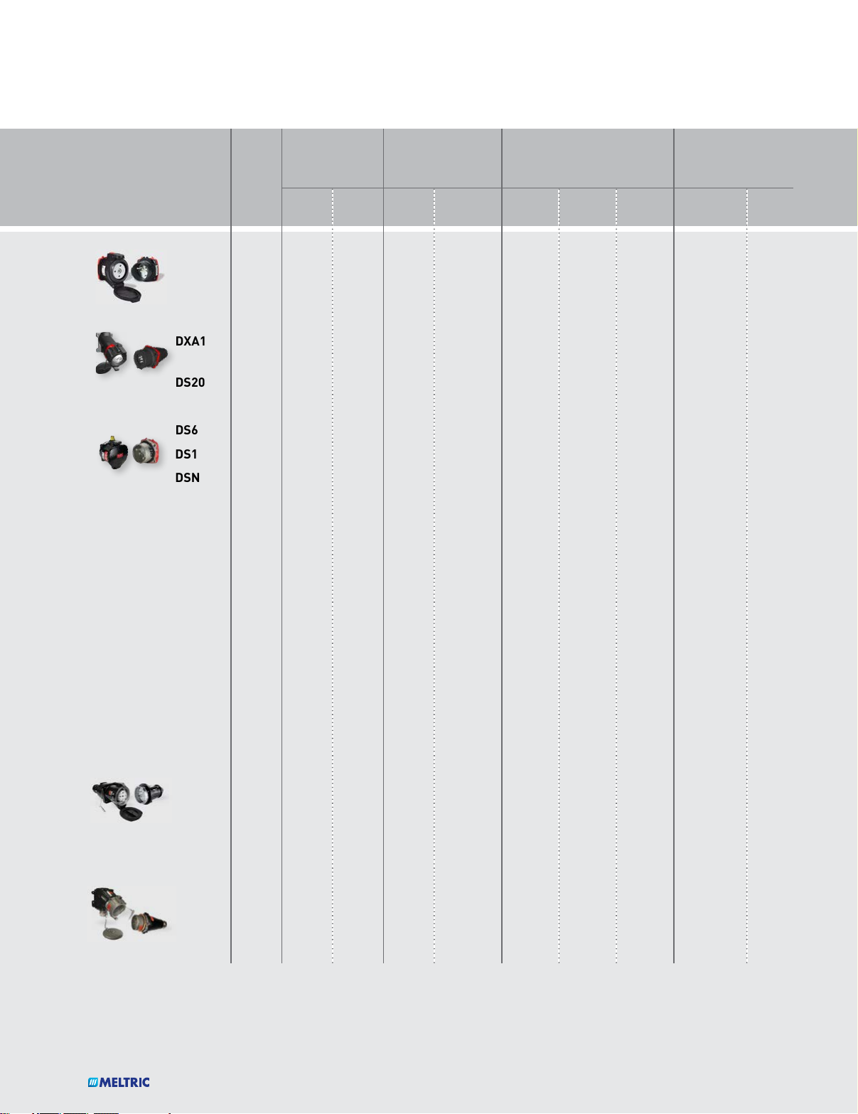
DXN
Hazardous rated, poly casings. From 20 – 60 A (1/4 – 20 hp) pg 173
DXA
Hazardous rated, metallic casings. 20 A pg 185
DSN/DS/DR/DSDC
Hazardous rated, metallic casings. 2 – 250 A (up to 100 hp) pg 189
DX
Hazardous rated, metallic casings. From 20 – 125 A pg 211
Multipin
Hazardous rated, 12 to 37 pins. 10 A pg 221
SPeX
Hazardous rated, up to 680 A, 1000VAC pg 227
• Reference
Accessories/Option pg 233
Technical Manual pg 243
Suffixes Quick Reference Guide pg 259
Old/New Accessories References pg 261
Parts Index pg 265
2
MELTRIC Corporation
The best in industrial wiring devices
At MELTRIC Corporation, our only business
is electrical plugs and receptacles. We are
focused on providing our customers with
the best overall value by offering the safest,
Product Technology & Safety
The technology behind MELTRIC’s products was developed
specifically to address the shortcomings and safety hazards
common with pin & sleeve type plugs and receptacles. In
1952, following the observation of an accident with a pin
and sleeve device, Gilles Marechal devised the concept of
combining the advantages of silver-nickel butt contacts and
the load making and breaking capabilities of a switch with
the convenience of a plug and receptacle. Shortly thereafter,
the first of these products was born. MELTRIC licensed this
technology in the early 1980’s and has been supplying its
products to North American customers ever since.
highest quality and most reliable plugs and
receptacles, and by backing them with
outstanding service and support.
Value
With their unique features and capabilities, MELTRIC products
provide users with a safer and more reliable product than
competitive pin and sleeve devices. MELTRIC’s butt-style
contacts provide longer operating lives, optional integral pilot
contacts reduce the need for additional connectors and our
switch-rated plugs and receptacles can eliminate the need
for auxiliary interlocks and disconnect switches, helping
users reduce equipment costs. These advantages, together
with competitive pricing, short lead times, and 5-year
warranty on electrical contacts, make MELTRIC’s products
the best overall value in the plug & receptacle/connector
market.
3

Service & Support
MELTRIC backs its superior products with outstanding service and support. A network of over 150 sales associates and over 2000
distributor locations throughout the US, Canada and Mexico make access to our product easy.
MELTRIC’s Customer Service group is trained to answer most questions on the spot and is located at our manufacturing
facility in order to help streamline the order fulfillment process. Our engineering team stands ready to provide both
application support and custom designed products incorporating MELTRIC and third party components into power distribution
products tailored to meet your needs. Friendly and personal assistance is only a toll free call away at (800) 433-7642.
Many of MELTRIC’s products are designed in a modular fashion, which permits cost effective stocking of components and
quick final assembly of the product. Together with efficient order handling by Customer Service, this helps MELTRIC to
provide the shortest lead times in the industry.
Quality
Quality is not just an inspection function at MELTRIC.
Quality starts with intelligent designs, robust materials,
clear procedures, process measurement and controls and
effective communications. It is completed by the care,
commitment and involvement of each of our employees.
MELTRIC is dedicated to the continuous improvement of
all its critical production and support processes and is ISO
9001:2015 certified. MELTRIC designs and manufactures
its products to exceed the requirements of applicable UL,
CSA and IEC standards.
Worldwide Availability
Marechal Technology products are
manufactured in North America,
Europe, South Africa and Australia.
MELTRIC supplies product directly from
its factory in Franklin, Wisconsin to
customers in the United States, Canada
and Mexico. For customers outside
of North America, product is provided
through other Marechal Electric Group
companies and sales agents.
SALES OFFICES & MANUFACTURING PLANTS
COMPANY SALES PRESENCE
SALES AGENTS & DISTRIBUTORS
4
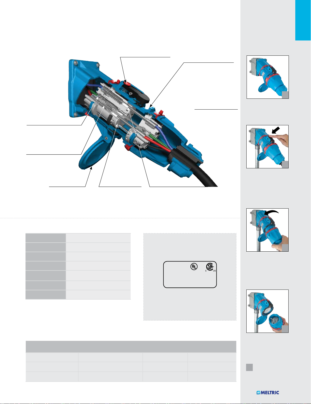
MELTRIC PRODUCT FEATURES...
0 10 20 30 40 50 60
70
60
50
40
30
20
10
Other guysOther guys
MeltricMeltric
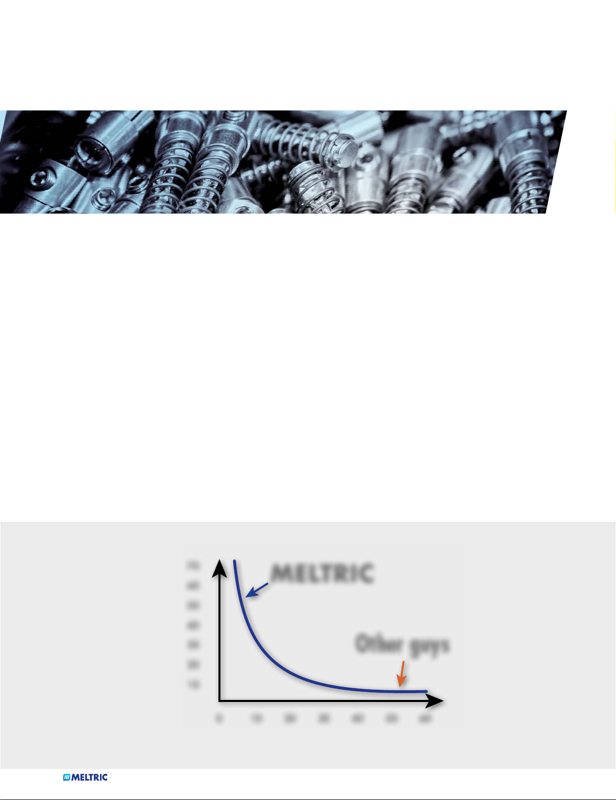
Spring-Loaded Butt Contacts
MELTRIC products feature spring-loaded, butt contacts
similar to those used in contactors and switchgear. These
contacts have numerous advantages, which help improve
electrical performance and user safety relative to pin and sleeve
contacts or the arcuate contacts used in twist-type devices.
Butt-style contacts ensure a very positive and consistent
connection. The spring-loading of these contacts, which is
accomplished with coil springs, provides a desirably high
contact force that remains constant over thousands of
operations. In addition, it automatically compensates for
any wear and/or deviations in contact length resulting from
manufacturing tolerances.
This is a critical point, as contact force is a key determinant
of the quality of a contact. As the accompanying chart
demonstrates, contact resistance increases as contact force
is reduced. Higher contact resistance generates more heat
70
60
50
and oxidation, both of which contribute to the deterioration
of the contact. This is a problem with pin and sleeve and
arcuate type contacts because their contact force varies with
manufacturing tolerances and is reduced due to wear that
occurs with normal use.
Most MELTRIC contacts close with a self-cleaning wiping
action. When the contacts initially mate, they are slightly
offset. In completing the connection, the plug contacts are
rotated across the receptacle contacts, helping to remove
deposits from the contact surfaces.
In conjunction with the ejection springs used on many
MELTRIC products, the spring-loaded contacts ensure a
quick breaking of the connection that is independent of the
motion of the user. By contrast, the disconnection speed of
pin and sleeve and twist-type devices is dependent upon the
motion of the user.
MELTRIC
40
30
(Force)
20
Contact Pressure
10
0 10 20 30 40 50 60
Other guys
Contact Resistance
5
...AND BENEFITS
Silver-Nickel Contact Material
MELTRIC uses solid silver-nickel (85%/15%) contacts. The
silver-nickel material has significant advantages over the
brass contacts commonly used on competitive devices.
Silver has very low initial contact resistance and is not negatively
affected by oxidation. This helps to give it excellent electrical
properties that are maintained even at high temperatures
and after tarnishing. Nickel is a much harder material and
contributes excellent mechanical properties. The combination
of silver and nickel results in a contact material that has both
superior electrical capabilities and excellent resistance to
wear. Silver-nickel only welds at extremely high pressure
and temperature, and thus, also withstands arcs very well.
These features make silver-nickel a commonly used contact
material by switchgear manufacturers.
By contrast, the brass material used in most competitive plug
and receptacles has a much higher initial contact resistance
and is negatively affected by oxidation. In an oxidized state,
the contact resistance of brass is more than 20 times higher
than that of silver-nickel. In addition, brass is a soft material
that wears rapidly. In use, brass pin and sleeve and arcuate
contacts suffer from the combined effects of the limitations
of the material and the design. As oxidation and wear
induced reductions in contact force occur, contact resistance
increases. This increases operating temperature, which
causes further oxidation and wear, perpetuating a vicious
cycle of degradation. Brass is not arc resistant and is not
suitable for making and breaking under load.
MATERIAL CONTACT RESISTANCE
NEW OXIDIZED
SILVER
SILVER-NICKEL
COPPER
BRASS
μΩ 25 μΩ
6
23
μΩ 60 μΩ
29
μΩ 400 μΩ
370
μΩ 1400 μΩ
Dead Front Construction
Most MELTRIC products feature dead front construction,
which greatly enhances safety by eliminating any unintended
access to live parts. On most MELTRIC products, the dead front
is accomplished with a safety shutter that can be opened only
by an appropriate mating plug. The live receptacle contacts
can only be accessed by the plug, after its insertion into the
receptacle. The design of the product also ensures that the
plug contacts are dead before the user can remove the plug
from the receptacle.
By contrast, pin and sleeve and twist-type devices do not have
a safety shutter. Access to live receptacle contacts is possible,
and on some devices the plug contacts may be live and
accessible when the plug is being removed.
6
MELTRIC PRODUCT FEATURES...
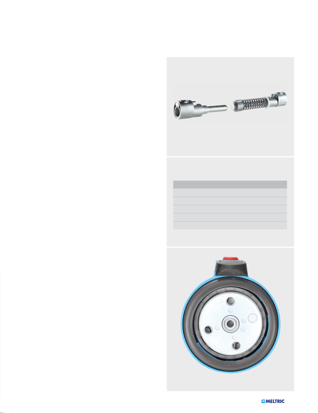
Push-Button Circuit Disconnection
To disconnect most MELTRIC products, the user simply needs
to press the pawl. This causes the circuit to be disconnected and
the plug to be ejected to its rest (off) position in the receptacle. If
desired, the user can then remove the plug from the receptacle
by rotating it slightly and then withdrawing it. This mode of
operation ensures that it is only possible to remove the plug
after its contacts have been de-energized.
Enclosed Arc Chambers
The contacts on most MELTRIC products make and break
within enclosed arc chambers. This ensures that the arcing
which normally occurs during the making and breaking of the
contacts is contained inside the device. This greatly enhances
safety and avoids potential injury to users and/or harm to the
outside environment.
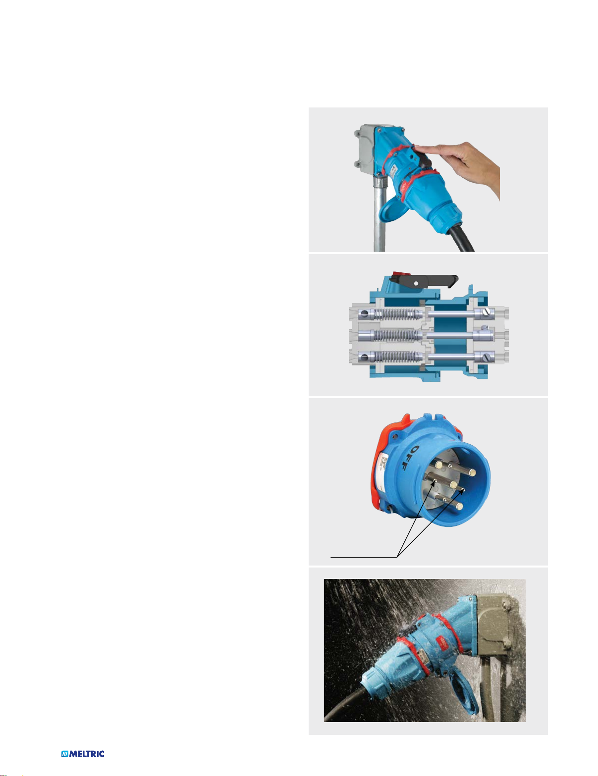
Optional Auxiliary/Pilot Contacts
Many MELTRIC products are available with optional auxiliary/
pilot contacts. These integral pilot contacts allow users the
convenience and flexibility of controlling auxiliary equipment,
monitoring parameters (such as motor temperature), and/or
communicating alarms through the same plug and receptacle
used to supply power to the equipment. Because the pilot
contacts are integral, they also facilitate the rapid change-out
or reconfiguration of equipment by eliminating the need for
hard wiring or multiple plug connections.
Automatic Watertightness
On most pin and sleeve devices, an additional plastic ring
must be tightened in order to ensure the achievement of rated
watertightness. Users frequently fail to do this, resulting in
leakage. MELTRIC solves this problem with its DS and DSN
Switch-Rated plugs and receptacles, which achieve their rated
watertightness of up to Type 4X/IP69/IP69K simply by mating
the plug with the receptacle. After the removal of the plug,
rated watertightness is maintained for the receptacle by simply closing the lid.
Auxiliary/Pilot
Contacts
7
...AND BENEFITS
Spring-Assisted Terminals
The loosening of terminal screws is a common cause for failure
on standard plugs and receptacles. MELTRIC provides a more
permanent and secure connection with its unique and patented
spring-assisted terminal design.
As the terminal screw is tightened against the conductor, the
associated pressure expands the split terminal body, causing a
spring ring surrounding the terminal to deform into an elliptical
shape. The natural tendency for the spring ring to return to
its original size and shape ensures that a constant pressure
is maintained on the conductor. This allows the terminal to
effectively compensate for strand settlement and conductor
yield, due to cold flow of the material, and provides superior
resistance to vibration, shock and thermal cycling.
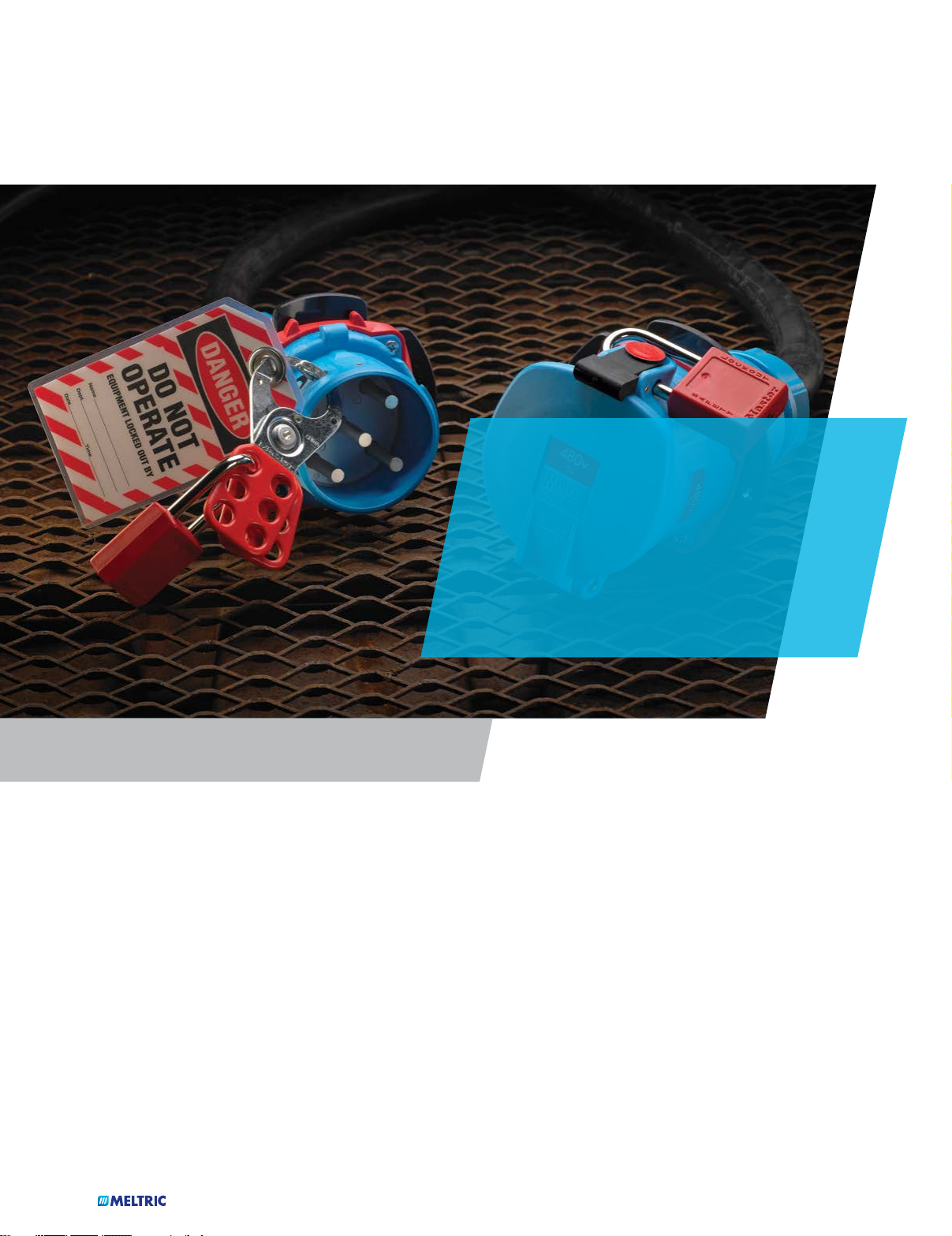
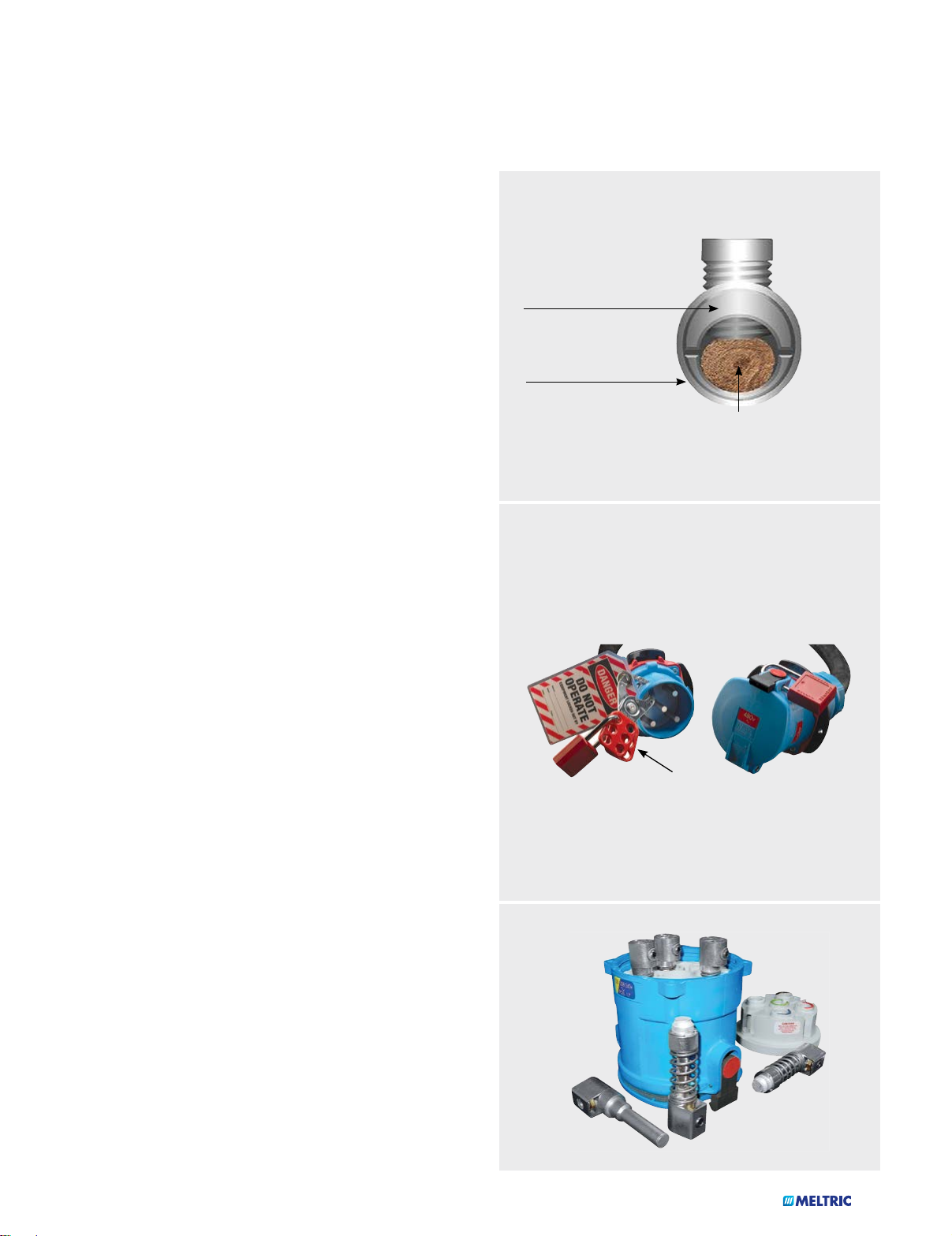
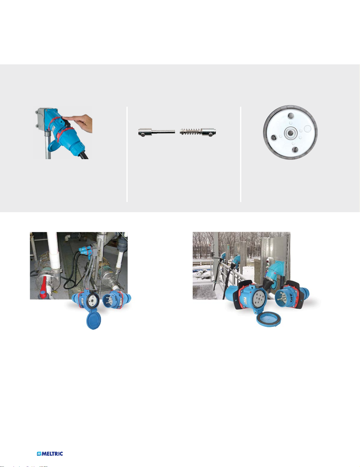
Lockout-Tagout Capability
SPLIT TERMINAL
(allows constant force)
ELLIPTICAL
DEFORMING RING
(prevents loosening)
CONDUCTOR
Most MELTRIC plugs and receptacles facilitate compliance
with OSHA lockout-tagout requirements. Only a lock or lockout
hasp and tag are needed to ensure that the plug is properly
locked out and tagged out. Additional mechanisms are not
required because the lockout provision is integral to the device
– it is always available when you need it. On most models the
lockout provision is a simple 5/16” hole in the plug shroud that
facilitates the insertion of a typical padlock or lockout hasp
which prevents the plug from being inserted into a receptacle.
An optional provision for locking out MELTRIC receptacles is
also available. In most cases this is accomplished via a specially
machined hole in the receptacle casing which allows insertion
of a padlock to secure the receptacle lid in a closed position.
This same optional provision can be used to prevent removal
of the plug if desired.
By comparison, in order to lockout most competitivepin and
sleeve type plugs, an additional third-party ‘lockout shield or
‘plug cap’ is required. These devices can be expensive and are
often times lost, broken, or not available when you need them.
Modular Construction
Due to the robust construction of MELTRIC devices, the
need to replace worn parts is rare. However, should they be
required, parts are readily available and reasonably priced.
The modular construction of most MELTRIC devices enables
easy replacement of parts in the field.
LOCKOUT HASP
8
MELTRIC PRODUCT SUMMARY...
Model
Amp
Rating
Maximum
Voltage Rating
Environmental
Ratings
Available Casing Materials
Maximum Number of
Contacts
VAC VDC Type IP Poly Metal SS Main Aux.
DSN20 20 600 - 4X 69/69K Poly - - 3P+N+G 2**
DSN30 30 600 - 4X 69/69K Poly - - 3P+N+G 2
DSN60 60 600 - 4X 69/69K Poly - - 3P+N+G 4
DSN150 150 600 - 4X 69/69K Poly Metal - 3P+N+G 6
DS20 20 600 -
DS30 30 600 -
DS60 60 600 -
DS100C 100 600 -
DS100 100 600 -
DS200 200 600 -
PN7c 15 480 130 -
3R
3R
3R
3R
3R
3R
+
+
+
+
+
+
- Poly - - 3P+N+G 2
- Poly - - 3P+N+G 4
- Poly Metal - 3P+N+G 4
- Poly Metal - 3P+N+G 4
- Poly Metal - 3P+N+G 6
- - Metal - 3P+N+G 6
*
66/67
Poly Metal SS 6P+G -
PN12c 2 600 130 -
Multipin Switch-Rated
PN12c 7.5 600 130 -
DSN24c 2 480 130 - 66/67 Poly - - 24 -
DSN24c 7.5 480 130 - 66/67 Poly - - 24 -
DS24c 2 250 130 - 54/55 - - SS 24 -
DS24c 7.5 250 130 - 54/55 - - SS 24 -
DSN37c 2 480 130 - 66/67 Poly - - 37 -
DSN37c 7.5 480 130 - 66/67 Poly - - 37 -
DS37c 2 480 130 - 54/55 - - SS 37 -
DS37c 7.5 480 130 - 54/55 - - SS 37 -
DN9c 20 480 130 - 54/55 - Metal - 9 -
DN20c 20 480 130 - 54/55 - Metal - 20 -
DS7c 30 600 130 - 54/55 Poly Metal - 7 3
DR7c 50 600 130 - 54/55 Poly Metal - 7 3
66/67
66/67
*
Poly Metal SS 11P+G -
*
Poly Metal SS 11P+G -
The indicated ratings do not apply to devices with SS casings.
*
+
Type 4X optional
** DSN20 auxiliary contacts just provide a continuity loop thru the receptacle to indicate that a plug is connected.
9
...AND SELECTION GUIDE
Current
Model
DSN20 Switch-Rated 3 hp 7.5 hp 7.5 hp 14 AWG 12 AWG Screw
DSN30 Switch-Rated 5 hp 10 hp 15 hp 14 AWG 8 AWG Screw
DSN60 Switch-Rated 7.5 hp 20 hp 20 hp 12 AWG 4 AWG Screw
DSN150 Switch-Rated 30 hp 75 hp 75 hp 4 AWG 2/0 AWG Screw
DS20 Switch-Rated 5 hp 7.5 hp 10 hp 14 AWG 8 AWG Screw
DS30 Switch-Rated 5 hp 15 hp 15 hp 12 AWG 4 AWG Screw
DS60 Switch-Rated 10 hp 25 hp 25 hp 10 AWG 2 AWG Screw
DS100C Switch-Rated 20 hp 50 hp 50 hp 10 AWG 2 AWG Screw
DS100 Switch-Rated 10 hp 30 hp - 4 AWG 2/0 AWG Screw
DS200 Switch-Rated 40 hp 100 hp 100 hp 4 AWG 4/0 AWG Screw
PN7c Current Interrupting - - - 18 AWG 10 AWG Screw
Interruption
Rating*
(see catalog section for other voltages)
240V - 3Ø 480V - 3Ø 600V - 3Ø Min Max
Horsepower Ratings
Main Contacts Wire
Size Capacity
Terminal Type
PN12c Current Interrupting - - - 18 AWG 14 AWG Solder/Crimp
PN12c Non-Current Interrupting - - - 18 AWG 14 AWG Solder/Crimp
DSN24c Current Interrupting - - - 18 AWG 14 AWG Solder/Crimp
DSN24c Non-Current Interrupting - - - 18 AWG 14 AWG Solder/Crimp
DS24c Current Interrupting - - - 18 AWG 14 AWG Solder/Crimp
DS24c Non-Current Interrupting - - - 18 AWG 14 AWG Solder/Crimp
DSN37c Current Interrupting - - - 18 AWG 14 AWG Solder/Crimp
DSN37c Non-Current Interrupting - - - 18 AWG 14 AWG Solder/Crimp
DS37c Current Interrupting - - - 18 AWG 14 AWG Solder/Crimp
DS37c Non-Current Interrupting - - - 18 AWG 14 AWG Solder/Crimp
DN9c Current Interrupting 3 hp 5 hp - 16 AWG 10 AWG Screw
DN20c Current Interrupting 1 hp 3 hp - 16 AWG 10 AWG Screw
DS7c Current Interrupting - - - 14 AWG 8 AWG Screw
DR7c Non-Current Interrupting - - - 14 AWG 8 AWG Screw
‘Switch-Rated’ and ‘Current Interrupting’ ratings apply to alternating current only.
*
10
MELTRIC PRODUCT SUMMARY...
Model
DR30 30 600 -
DR50 50 600 -
DR100 100 600 -
DR150 150 600 -
Standard
DR250 250 600 -
DR400 400
PN20 20
PNHT 30 480 130 - 44 - Metal - 3P+N+G -
DSDC1 20 - 250
DSDC1 15 - 600
DSDC1 10 - 750
DSDC3 30 - 250
DSDC3 30 - 600
DSDC3 20 - 750
Direct Current
DSDC6 60 - 250
DSDC6 50 - 600
DSDC6 30 - 750
DSDC9 100 - 250
DSDC9 60 - 600 4X - Poly - - 2P+G -
DSDC2 200 - 250 3R - - Metal - 2P+G -
DSDC2 100 - 600 3R - - Metal - 2P+G -
Amp
Rating
Maximum
Voltage Rating
Environmental
Ratings
Available Casing Materials
Maximum Number
of Contacts
VAC VDC Type IP Poly Metal SS Main Aux.
480
480
**
*
3R
3R
3R
3R
3R
- -
- -
3R
3R
3R
3R
3R
3R
3R
3R
3R
3R
+
+
+
+
+
+
+
+
+
+
+
+
+
+
+
- Poly - - 3P+N+G 2
- Poly - - 3P+N+G 4
- Poly Metal - 3P+N+G 4
- Poly Metal - 3P+N+G 6
- - Metal - 3P+N+G 6
54/55
55
±
±
- Metal - 3P+G 2
Poly Metal SS 3P+N+G -
- Poly - - 2P+G -
- Poly - - 2P+G -
- Poly - - 2P+G -
- Poly - - 2P+G -
- Poly - - 2P+G -
- Poly - - 2P+G -
- Poly Metal - 2P+G -
- Poly Metal - 2P+G -
- Poly Metal - 2P+G -
- Poly Metal - 2P+G -
PFQ300 300 600 250 - 66/67 - Metal - 3P+N+G 8
PF300 300 600 250 - 66/67 - Metal - 3P+N+G 4
PF400 400 600 250 - 66/67 - Metal - 3P+N+G 4
PF600 600 600 250 - 66/67 - Metal - 3P+N+G 4
SP 600 1000 1500 - 66/67 Poly - - 1P 2++
CS1000 400 1000 1500 - 66/67 Poly - - 1P -
High Ampacity
600 VAC available at 15 A and less
*
600 VAC available at 350 A and less
**
+
Type 4X optional
± IP66/IP67 optional
++ SP auxiliary contacts just provide a continuity loop thru the receptacle to indicate that a plug is connected.
11

...AND SELECTION GUIDE
Current
Model
DR30 Non-Current Interrupting - - - 14 AWG 8 AWG Screw
DR50 Non-Current Interrupting - - - 12 AWG 4 AWG Screw
DR100 Non-Current Interrupting - - - 10 AWG 2 AWG Screw
DR150 Non-Current Interrupting - - - 4 AWG 2/0 AWG Screw
DR250 Non-Current Interrupting - - - 4 AWG 4/0 AWG Screw
DR400 Non-Current Interrupting - - - 2 AWG 500 MCM Screw
PN20 Current Interrupting - - - 14 AWG 8 AWG Screw
PNHT Non-Current Interrupting - - - 14 AWG 8 AWG Screw
DSDC1 Non-Current Interrupting - - - 14 AWG 8 AWG Screw
DSDC1 Non-Current Interrupting - - - 14 AWG 8 AWG Screw
DSDC1 Non-Current Interrupting - - - 14 AWG 8 AWG Screw
DSDC3 Non-Current Interrupting - - - 12 AWG 4 AWG Screw
DSDC3 Non-Current Interrupting - - - 12 AWG 4 AWG Screw
DSDC3 Non-Current Interrupting - - - 12 AWG 4 AWG Screw
DSDC6 Non-Current Interrupting - - - 10 AWG 2 AWG Screw
DSDC6 Non-Current Interrupting - - - 10 AWG 2 AWG Screw
DSDC6 Non-Current Interrupting - - - 10 AWG 2 AWG Screw
DSDC9 Non-Current Interrupting - - - 4 AWG 2/0 AWG Screw
DSDC9 Non-Current Interrupting - - - 4 AWG 2/0 AWG Screw
DSDC2 Non-Current Interrupting - - - 4 AWG 4/0 AWG Screw
DSDC2 Non-Current Interrupting - - - 4 AWG 4/0 AWG Screw
Interruption
Rating*
(see catalog section for other voltages)
240V - 3Ø 480V - 3Ø 600V - 3Ø Min Max
Horsepower Ratings
Main Contacts Wire
Size Capacity
Terminal Type
PFQ Non-Current Interrupting - - - 2 AWG 600 MCM Lug
PF300 Non-Current Interrupting - - - 2 AWG 600 MCM Lug
PF400 Non-Current Interrupting - - - 2 AWG 600 MCM Lug
PF600 Non-Current Interrupting - - - 2 AWG 600 MCM Lug
SP Non-Current Interrupting - 500 hp 500 hp 2/0 AWG 777 MCM Lug
CS1000 Non-Current Interrupting - - - 1/0 AWG 444 MCM Lug
12
MELTRIC PRODUCT SUMMARY...
Model
DXN20 20 600 - - 66/67 Poly - - 3P+N+G -
DXN30 30 600 - - 66/67 Poly - - 3P+N+G 2
DXN60 60 600 - - 66/67 Poly - - 3P+N+G 2
DXA1 20 600 - - 66/67 - Metal - 3P+N+G -
DS20 20 600 - 4X - Poly - - 3P+N+G 2
DS30 30 600 - 4X - Poly - - 3P+N+G 4
DS60 60 600 - 4X - - Metal - 3P+N+G 4
Hazardous Location
DS100C 100 600 - 4X - Poly Metal - 3P+N+G 4
DSN150 150 600 - 4X - - Metal - 3P+N+G 6
DS200 200 600 - 4X - - Metal - 3P+G 6
DR30 30 600 - 4X - Poly - - 3P+N+G 2
DR50 50 600 - 4X - Poly - - 3P+N+G 4
DR250 250 600 - 4X - - Metal - 3P+G 6
Amp
Rating
Voltage Rating
VAC VDC Type IP Poly Metal SS Main Aux.
Maximum
Environmental
Ratings
Available Casing Materials
Maximum Number
of Contacts
DSDC1 20 - 250 4X - Poly - - 2P+G -
DSDC3 30 - 250 4X - Poly - - 2P+G -
DSDC6 60 - 250 4X - Poly Metal - 2P+G -
DSDC9 100 - 250 4X - - Metal - 2P+G -
DSDC2 200 - 250 4X - - Metal - 2P+G -
DX1 20 750 - - 65 - Metal - 3P+N+G -
DX3 32 750 - - 65 - Metal - 3P+N+G -
DX6 63 750 - - 65/66 - Metal - 3P+N+G -
DX9 125 750 - - 65/66 - Metal - 3P+N+G -
PXN12c 10 220 - - 65/66 - Metal - 11P+G -
DXN25c 10 440 - - 66/67 - Metal - 24P+G -
DXN37c 10 220 - - 66/67 - Metal - 36P+G -
SPeX 680 1000 - - 65/66 Poly - - 1P 2*
SPeX auxiliary contacts just provide a continuity loop thru the receptacle to indicate that a plug is connected.
*
13

...AND SELECTION GUIDE
Current
Model
DXN20 Current Interrupting 2 hp 5 hp 5 hp 16 AWG 10 AWG Screw
DXN30 Current Interrupting 5 hp 10 hp 15 hp 14 AWG 6 AWG Screw
DXN60 Current Interrupting 7.5 hp 20 hp 20 hp 10 AWG 4 AWG Screw
DXA1 Current Interrupting 2 hp 5 hp 5 hp 16 AWG 10 AWG Screw
DS20 Non-Current Interrupting 5 hp 7.5 hp 10 hp 14 AWG 8 AWG Screw
DS30 Non-Current Interrupting 5 hp 15 hp 15 hp 14 AWG 4 AWG Screw
DS60 Non-Current Interrupting 10 hp 25 hp 25 hp 10 AWG 2 AWG Screw
DS100C Non-Current Interrupting 20 hp 50 hp 50 hp 10 AWG 2 AWG Screw
DSN150 Non-Current Interrupting 30 hp 75 hp 75 hp 4 AWG 2/0 AWG Screw
DS200 Non-Current Interrupting 40 hp 100 hp 100 hp 4 AWG 4/0 AWG Screw
DR30 Non-Current Interrupting - - - 14 AWG 8 AWG Screw
DR50 Non-Current Interrupting - - - 14 AWG 4 AWG Screw
DR250 Non-Current Interrupting - - - 4 AWG 4/0 AWG Screw
Interruption
Rating
(see catalog section for other voltages)
240V - 3Ø 480V - 3Ø 600V - 3Ø Min Max
Horsepower Ratings
Main Contacts Wire
Size Capacity
Terminal Type
DSDC1 Non-Current Interrupting - - - 14 AWG 8 AWG Screw
DSDC3 Non-Current Interrupting - - - 14 AWG 4 AWG Screw
DSDC6 Non-Current Interrupting - - - 10 AWG 2 AWG Screw
DSDC9 Non-Current Interrupting - - - 4 AWG 2/0 AWG Screw
DSDC2 Non-Current Interrupting - - - 4 AWG 4/0 AWG Screw
DX1 Current Interrupting - - - 14 AWG 8 AWG Screw
DX3 Current Interrupting - - - 14 AWG 8 AWG Screw
DX6 Current Interrupting - - - 6 AWG 1/0 AWG Screw
DX9 Current Interrupting - - - 2 AWG 2/0 AWG Screw
PXN12c Non-Current Interrupting - - - 16 AWG 14 AWG Solder/Crimp
DXN25c Non-Current Interrupting - - - 16 AWG 14 AWG Solder/Crimp
DXN37c Non-Current Interrupting - - - 16 AWG 14 AWG Solder/Crimp
SPeX Non-Current Interrupting - - - 2/0 AWG 750 MCM Lug
14
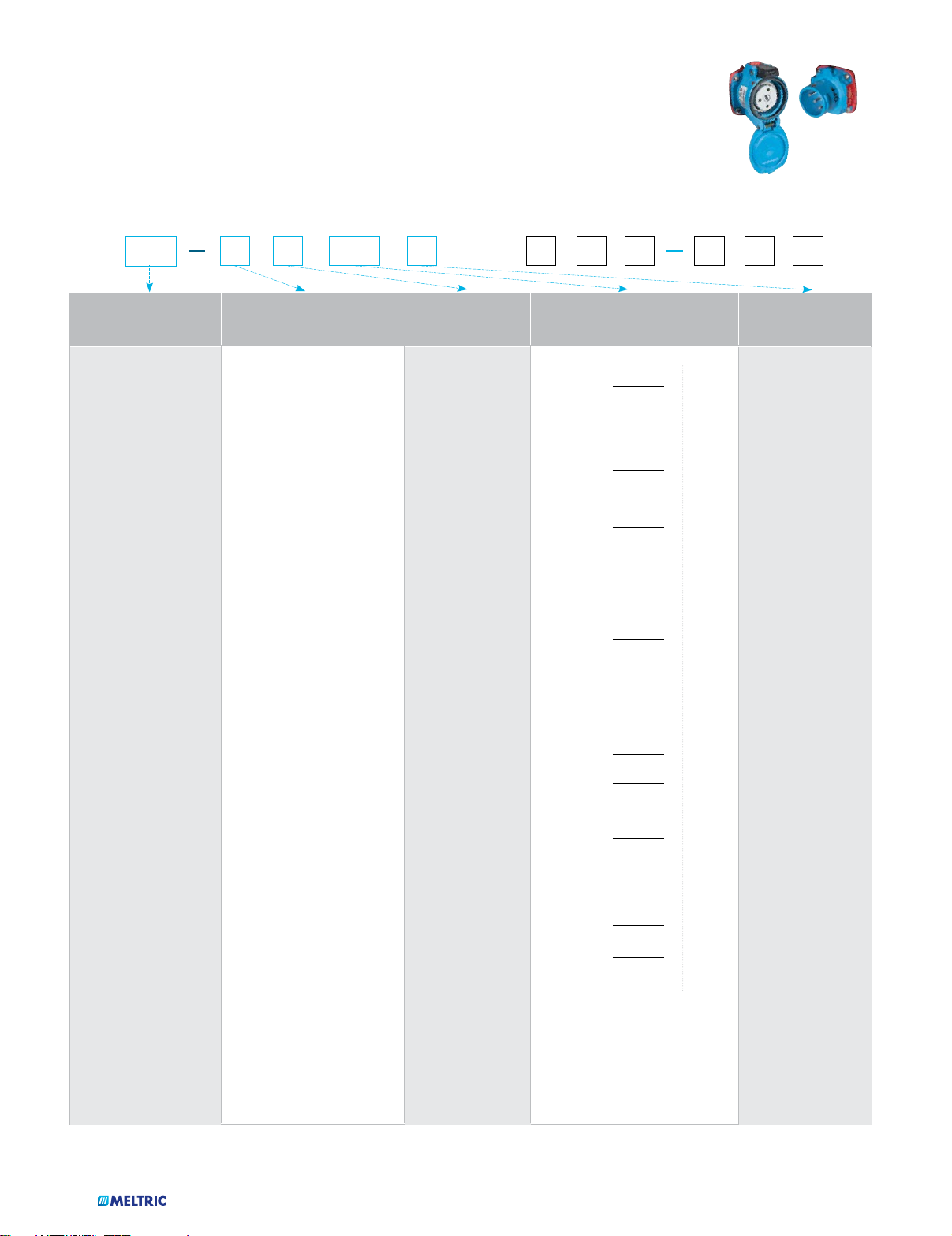
MELTRIC PART NUMBERING...
First seven (7) digits for a basic inlet
One (1) to six (6) suffixes for special features
or receptacle part number
1 2
AMP (A) Voltage Polarization
Rating Position Voltage Hz
MELTRIC
Product Line Type
and Casing Material
PN/PN7c
01 = Blue Poly
09 = Blue Metal
PN12c
03 = Blue Poly
07 = Blue Metal
PXN12c
06 = Black Metal
DN
19 = Blue Metal
DXN
22 = Black Poly
DXA1
28 = Black Metal
DX
26 = Black Metal
DS
33 = Blue Poly
35 = Black Poly
36 = Black Metal (HazLoc)
37 = Blue Metal
DXN25/37c
36 = Black Metal
DR
31 = Blue Poly
35 = Black Poly
36 = Black Metal (HazLoc)
39 = Blue Metal
SPeX
42 = Black Poly
CS1000/SP
45 = Black Poly
PFQ
47 = Gray Metal
PF
49 = Gray Metal
DSN
63 = Blue Poly
65 = Black Poly
66 = Black Metal (HazLoc)
69 = Blue Metal
3
DSN
1 = 20
3 = 30
6 = 60
9 = 150
DS
1 = 20
3 = 30
6 = 60/100C
9 = 100
2 = 200*
DR
1 = 30
3 = 50
6 = 100
9 = 150
2 = 250*
4 = 400*
PN20
N = 20 (IP66/
IP67)
S = 20 (IP54/
IP55)
PNHT
2 = 20
DXN
1 = 20
3 = 30
6 = 60
DXA1
1 = 20
*
4 5 6 7
DX
2 = 20*
3 = 30*
6 = 60*
9 = 100*
PF
3 = 300*
4 = 400*
6 = 600*
PFQ
3 = 300*
DN
1 = 20*(DN9)
6 = 20*(DN20)
Available in metal only.
Form and Mounting Phasing
Female
4 = Receptacle
Male
8 = Inlet
DX, DXN37c,
PXN12c, SPeX
Only
Female
0 = Receptacle
on box
3 = Connector
4 = Receptacle
Male
1 = Plug
6 = Inlet on Box
X X X Y Y Y
01 = 50
220 - 250
380 - 440
02 = 20/24 60
03 = 50
04 = 60
110 - 130
190 - 230
255 - 277
440 - 480
06 = 25/28 50
07 = 60
110 - 125
220 - 250
08 = 20/24 50
09 = 480/500 50
10 = 110/130 DC
11 = 400
12 = 200
115 - 127
200 - 220
115 - 127
200 - 220
13 = 40/48 50
AC
2 = 2P+G AC
3 = 3P+G AC
5 = 1P+N+G AC
6 = 2P+N+G AC
7 = 3P+N+G AC
+
= 2P AC
A
+
= 3P AC
B
+
= 3P+N AC
C
+
= 1P+N AC
D
+
= 2P+N AC
G
DC
++
= 2P+G DC
8
9 = 2P+G DC
+
= 2P DC
Z
= 2P+2P+G DC
P
+
For 50V or less only.
++
Includes jumpers.
14 = 347/600 60
16 = 60
17* = 60
120 - 127
208 - 220
110 - 125
220 - 250
18* = 347/600 60
19 = 50
380 - 400
660 - 690
20 = 220/250 DC
22 = 577/1000 50
23* = 60
24* = 60
For DS100C and DR devices.
*
120 - 127
208 - 220
255 - 277
440 - 480
Notes: • On metal devices, inlets are not painted, receptacles are painted.
• This is the Keying Standard for MELTRIC products. Suffixes are available to accommodate non-interchangeable devices of the same size at the same voltage.
Please ask for more details.
15
...AND ORDERING GUIDE
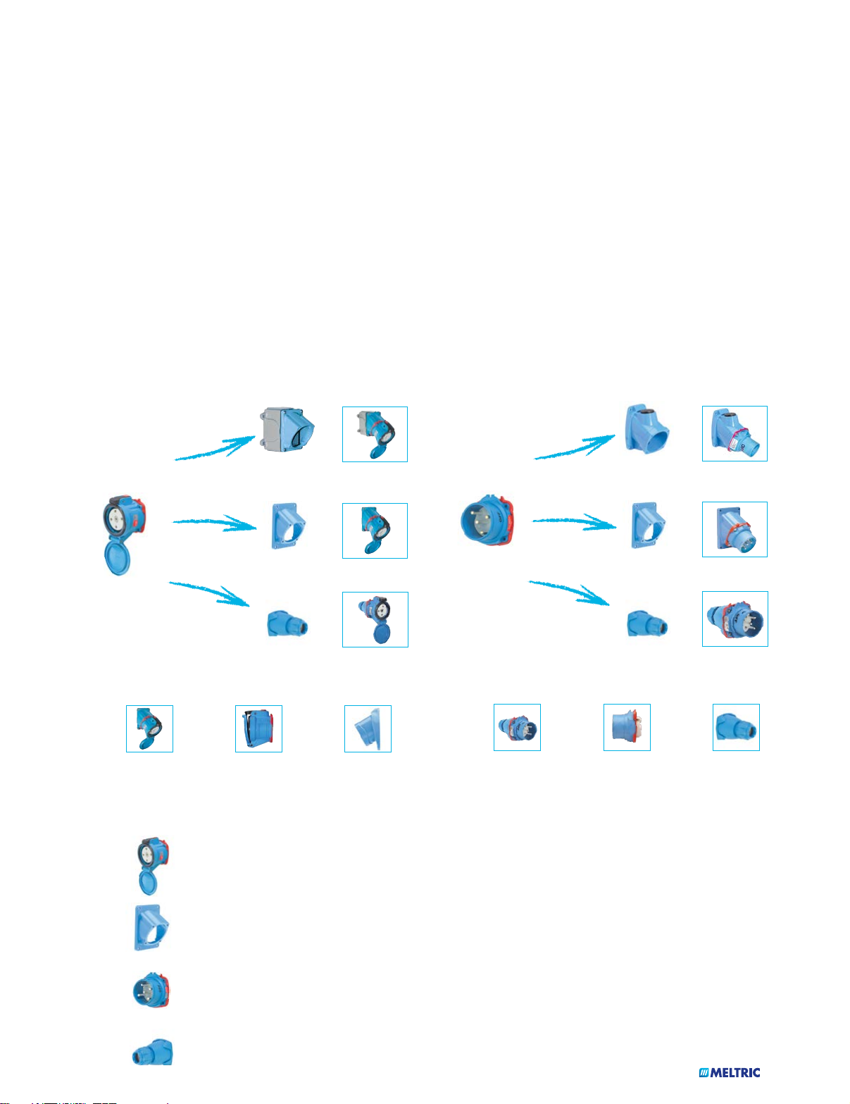
A MODULAR SYSTEM
MELTRIC products are ordered and assembled in a modular fashion. Customers should select the desired male inlet and
female receptacle part numbers. Then matching accessories such as handles, angles, and junction boxes should be identified
and added to the order to create plugs, connectors, or other configurations. This modular system allows MELTRIC to build
and ship product to customer specifications in a very short time - 90% of orders ship by the next business day.
FEMALE
RECEPTACLE
EXAMPLE
Female Receptacle
on Angle
Angle with
Junction Box
Angle Adapter
Handle
Female Receptacle
on Angle with
Junction Box
=
Female Receptacle
=
=
on Angle
Connector
MALE
INLET
Poly Conduit
Entry Box
=
Angle Adapter
=
Handle
=
EXAMPLE
= +
Female Receptacle Angle Adapter Male Plug Male Inlet Handle
= +
Male Inlet on Poly
Conduit Entry Box
Male Inlet
on Angle
Plug
TYPICAL ORDER
63-34047 Female Receptacle
512M3 Angle Adapter for Female
63-38047 Male Inlet
512P0D21 Handle for Male
16
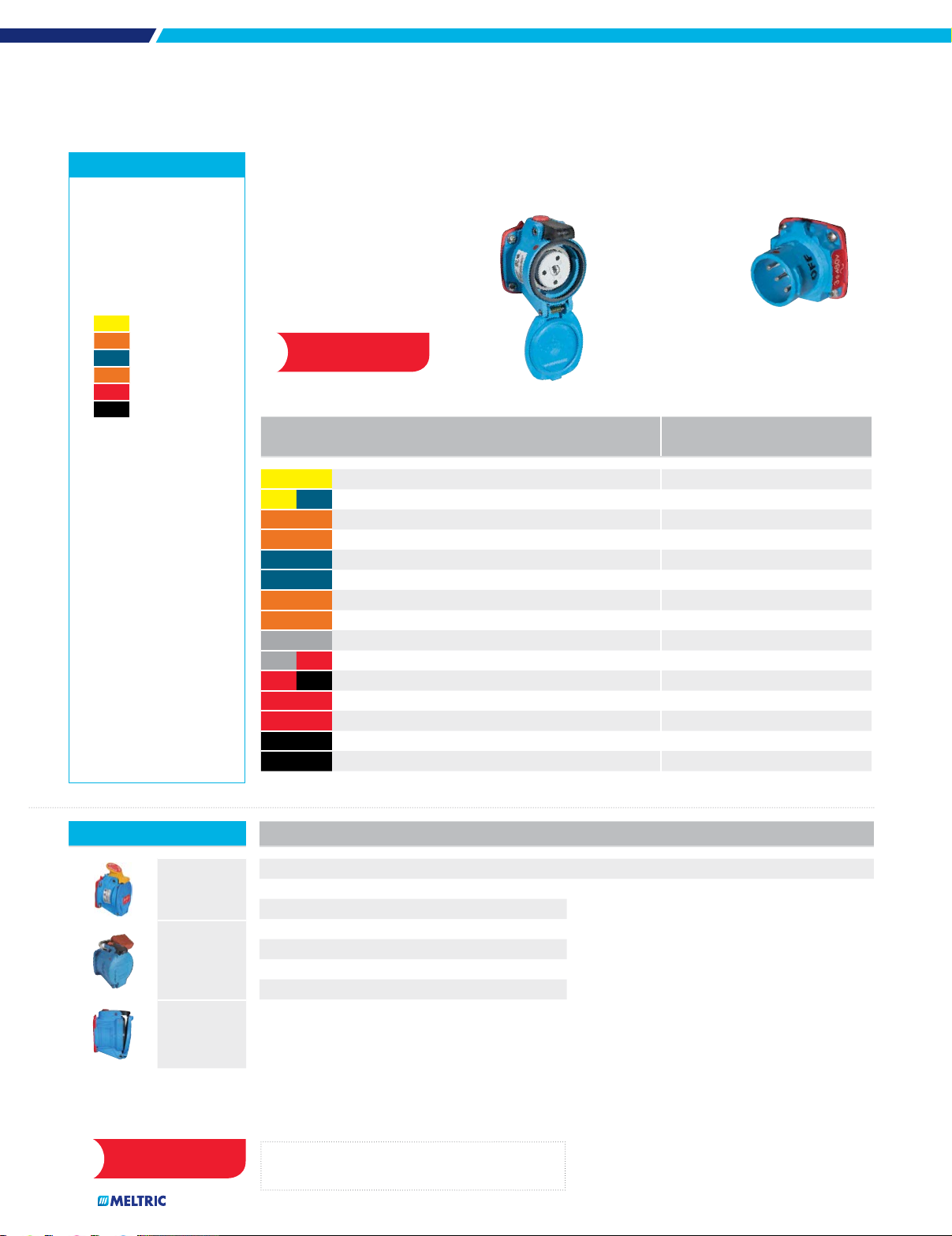
SWITCH-RATED
Plugs & Receptacles
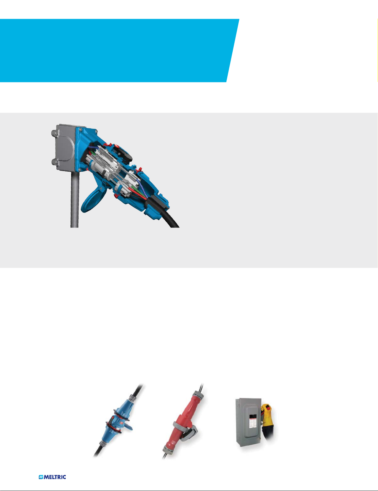
THE MAIN DIFFERENCES
DECONTACTOR
Technology
Pressing the pawl/button on the receptacle will safely switch off
power to the load. The plug can then be withdrawn in complete safety.
(Cutaway model shown for illustration purposes)
®
Like most MELTRIC products, Switch-Rated plugs and
receptacles feature (see pgs 7-8)
u Spring-loaded butt contacts
u Silver-nickel contact materials
u Dead front design
u Enclosed arc chambers
u Spring-assisted terminals
u Auxiliary contacts
MELTRIC Switch-Rated plugs and receptacles have
additional features, including:
u UL & CSA switch-ratings
u Horsepower ratings
u Short circuit ratings up to 100 kA
in fuse protected circuits
Switch and Hp Ratings
MELTRIC Switch-Rated products are a combination plug, receptacle and non-fusible disconnect switch in the same device. Their
integral switch technology ensures the safe breaking of resistive and inductive loads (up to 100 hp or 200 A) before an operator
can physically remove the plug from the receptacle.
They are UL and CSA approved for both “branch circuit” and “motor circuit” disconnect switching, making them ideal for connecting
motors, welding machines and virtually any other electrical equipment.
Short Circuit Ratings
MELTRIC Switch-Rated plugs and receptacles help ensure worker safety even in fault conditions. They are rated to close into and
withstand short circuit currents of up to 100 kA. The protection far surpasses that offered by other plugs and receptacles, and
even surpasses the short circuit protection offered by most manual motor controllers and mechanical interlocks.
=
To match the functionality of a Switch-Rated device, it would take a
pin and sleeve plug plus a non-fused safety switch.
17
+
UL & CSA Standards
Test requirements and ratings comparison table
To achieve their UL 2682 switch ratings, MELTRIC Switch-Rated plugs and receptacles have passed tests that far exceed those
of ordinary plugs and receptacles. These tests include horsepower/locked rotor overload tests from the UL 508 Standard for
Industrial Control Equipment and electrical endurance and short-circuit make-and-withstand testing from the UL 98 standard
for Enclosed and Dead Front Switches.
To illustrate how the electrical and mechanical endurance of MELTRIC Switch-Rated plugs and receptacles far exceeds standard
plugs, the following chart compares the test requirements for achieving a Switch-Rated plug & receptacle listing with those
required for a standard pin and sleeve plug & receptacle listing.
UL Subject 2682
(used for both UL & CSA listings)
(Tests passed by MELTRIC devices)
Test
UL 1682 & CSA 22.2 No. 182.1
Plugs, Receptacles & Cable Connectors of the Pin & Sleeve Type Switch-Rated Plugs & Receptacles
Non-Current Interrupting Break
(minimum requirements)
Current Interrupting
(minimum requirements)
Motor Circuit/Branch Circuit Disconnect Switching
Temperature Rise < 30°C < 30°C < 30°C
Voltage Withstand 3,000VAC for 1 Minute 3,000VAC for 1 Minute 3,000VAC for 1 Minute
Overload
General Use Devices
Mechanical Endurance
(Plus Req’d Electrical Opns)
3 Operations
@ 150% Rated Current
(p.f. = .75 - .80)
15-20 A = 5000 Operations
21-63 A = 2000 Operations
64-250 A = 250 Operations
50 Operations
@ 150% Rated Current
(p.f. = .75 - .80)
15-20 A = 0 Operations
21-63 A = 1000 Operations
64-250 A = 500 Operations
50 Operations
@ 150% Rated Current
(p.f. = .75 - .80)
4000 Cycles
15-20 A = 5000 Operations
1
1
6000 Operations
@ Rated Current & Voltage
(p.f. = .75 - .80)
Electrical Endurance
(with load)
21-63 A = 1000 Operations
–
64-250 A = 250 Operations
@ Rated Current & Voltage
(p.f. = .75 - .80)
Overload - Locked Rotor
(Horsepower Rated Devices)
Short Circuit
Withstand
Short Circuit
Closing
1
Testing alternates between mechanical & electrical operations. This reduces the severity of the electrical test by allowing additional cooling time during electrical testing.
+
All MELTRIC Switch-Rated devices are UL listed with short circuit ratings of at least 65kA achieved at 600VAC and ≤ .15 power factor.
–
–
(600V and ≤ .50 power factor)
– –
50 Operations
@ 600% of Full Load Motor
Current (p.f. = .40 - .50)
≥ 10 kA
+
(600V and ≤ .50 power factor)
(600V and ≤ .50 power factor)
50 Operations
@ 600% of Full Load Motor
Current (p.f. = .40 - .50)
≥ 10 kA
≥ 10 kA
+
+
18

BENEFITS OF USING
MELTRIC SWITCH-RATED DEVICES
Ensure Worker Safety
Switch-Rated plugs and receptacles ensure safety by eliminating hazards associated with pin and sleeve and twist-type devices.
uThe integral switching function ensures that the plug contacts are de-energized before an operator can remove the plug from
the receptacle. The dead-front design prevents unintended access to live parts.
uSpring-loaded, silver-nickel butt-style contacts maintain proper contact force, withst and arcing, resist wear, and maintain
low contact resistance. This ensures the integrity of the connection over thousands of operations and eliminates performance
and safety problems common to plugs with brass contacts.
uSpring-loaded plug and receptacle disengagement with push button operation ensures fast and easy load breaking, which
minimizes arcing during disconnection. Enclosed arc chambers eliminate arc flash hazards.
uHorsepower, switch, and short-circuit ratings provide additional protection during locked-rotor or other significant overload situations.
Simplify Code Compliance
Switch-Rated devices provide a simple and
cost-effective means of helping facilities
to achieve compliance with the National
Electrical Code and NFPA 70E.
NEC Compliance
Articles 430.101 to 430.113 of the National Electrical Code regulate
the means of motor disconnection (Canadian Electrical Code
section 28-600–28-604). They require motors to have readily
accessible, ‘line of sight’ disconnects that are an approved
switch or a properly rated plug and receptacle.
u430.102 A disconnecting means must be located in sight of
the motor and driven equipment.
u430.107 The disconnecting means must be readily accessible.
u430.109 The disconnecting means may be an approved
switch or horsepower rated plug and receptacle.
MELTRIC Switch-Rated plugs and receptacles are both
horsepower and switch-rated. They can function as a ‘line of sight’
disconnect in addition to providing a convenient plug and
play power connectionfor the motor. Installing a switch-rated
device eliminates the need for an auxiliary disconnect switch.
NFPA 70E (CSA Z462)
This OSHA consensus standard covers electrical safety-related
work practices and procedures for employees who work on or
near exposed energized electrical conductors or other live
circuit parts. Relevant requirements include:
Power must be proven to be off before work can be
performed. This requires:
u The safe interruption of the load and opening of
the disconnect
uVisual verification/voltage testing to ensure de-energization
The potential electrical hazard must be identified
and documented.
u An arc flash risk assessment must be performed
uFlash protection boundaries must be determined
Appropriate steps must be taken to protect persons working
near live parts or within the flash protection boundary.
uPPE must be worn based on incident energy exposure
levels (cal/cm2)
uOnly properly qualified persons are allowed to perform work
19
...THROUGHOUT YOUR FACILITY
Wiring and connection systems utilizing conventional switches and/or pin & sleeve devices would typically require all of the previously
listed protective measures to comply with NFPA 70E or CSA Z462. By using MELTRIC Switch-Rated plugs and receptacles to
connect equipment, users can very simply comply with these requirements.
Switch ratings ensure the safe interruption of the load. Visual verification that the power is off is provided when the plug is
removed from the receptacle. A dead front design prevents an operator from being exposed to live parts, eliminating the need to
perform hazard analysis, establish flash protection boundaries and use electrical personal protective equipment.
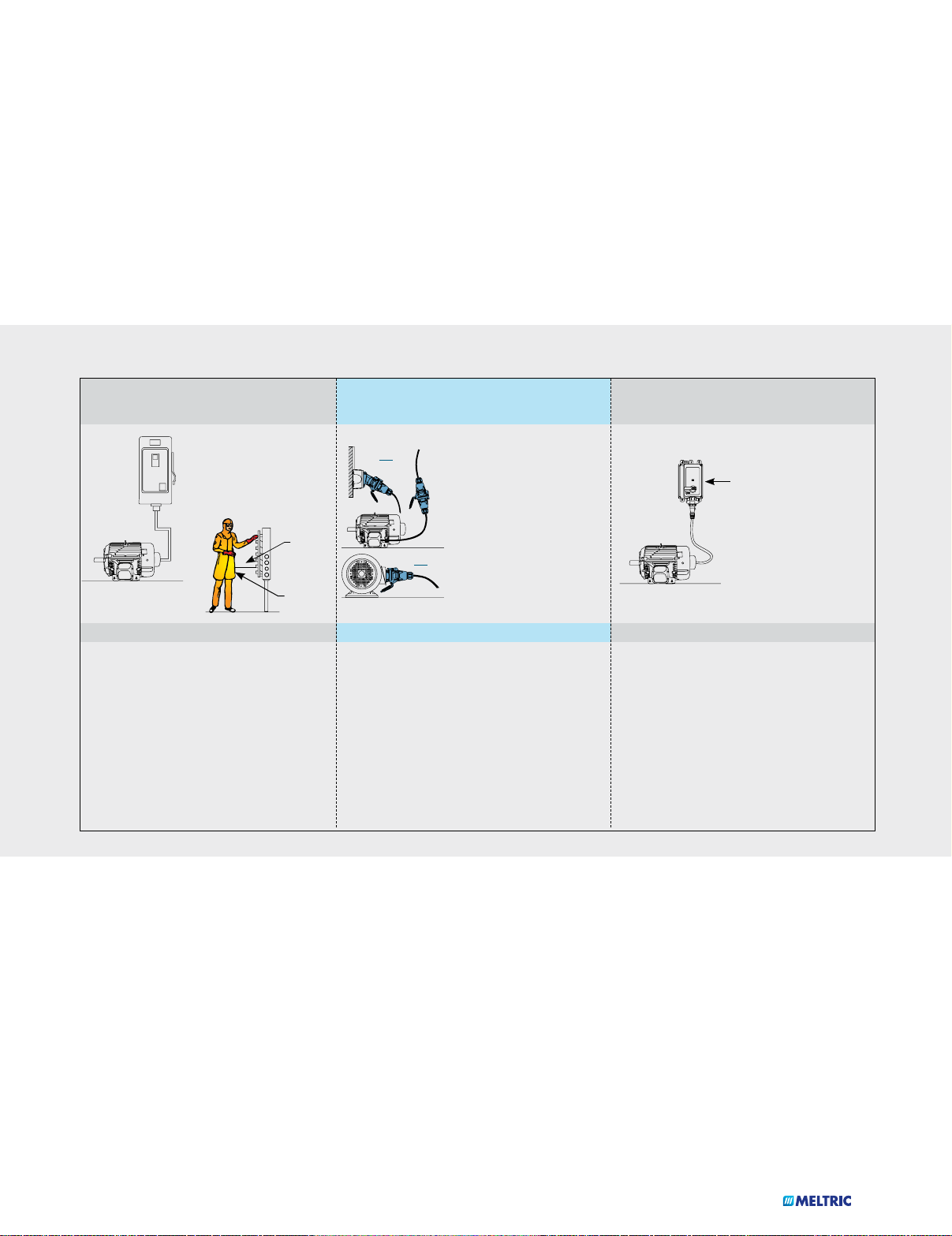
A Comparison of the Motor Change-Out Process
MOTOR HARD-WIRED TO A
BLADED DISCONNECT SWITCH
The disconnect switch may be
difficult to install in “line of
sight” of the motor.
MOTOR CHANGE-OUT PROCESS
1. Switch disconnect to OFF position
2. Apply lockout/ tagout
3. Perform Shock/Arc Flash Risk Assessment
4. Obtain permit for energized electrical work
5. Suit up with appropriate PPE
6. Remove the disconnect switch cover
7. Voltage test to verify deenergization
8. Disconnect motor from hard-wiring
9. Remove old/install new motor
10. Connect new motor to hard-wiring
11. Jog the motor to ensure proper rotation
18”
Qualified
Worker
w/PPE
MOTOR CONNECTED WITH A
MELTRIC MOTOR PLUG
u Cord connection allows easy
OR
MOTOR CHANGE-OUT PROCESS
1. Depress the pawl on the receptacle to break
the circuit
2. Mechanic removes plug from receptacle
3. Apply lockout/tagout as required
4. Mechanic removes old/installs new motor
5. Mechanic inserts plug into receptacle
“line of sight” location
u Dead front eliminates access
to live parts and need for
cumbersome PPE
u Ability to safely make &
break under load eliminates
the need for interlocks
OR
u ≥10k A short circuit make-
and-withstand rating ensures
safety during reenergization
MELTRIC Makes it
Safe & Easy
MOTOR CONNECTED WITH A
COMPETING PLUG & RECEPTACLE
u Expensive mechanical
interlocks are required
since these plugs &
receptacles cannot safely
make & break under load
u The interlock must be
mounted on a fixed
surface this may make
“line of sight” location
more difficult
MOTOR CHANGE-OUT PROCESS
1. Open interlock switch
2. Determine PPE requirements and obtain permit for
electrical work
3. Remove interlock cover
4. Verify deenergization with a voltmeter test
5. Remove plug
6. Apply lockout/tagout as required
7. Remove old/install new motor
8. Insert plug into receptacle
Reduce Equipment and Installation Costs
The ability of MELTRIC Switch-Rated devices to safely make and break under full load eliminates the need for the expensive interlocks
that are required with pin and sleeve devices. Their ability to function as the NEC required ‘line of sight’ disconnect switch eliminates the
need for auxiliary disconnect switches. Optional pilot contacts can eliminate the need of auxiliary connectors in control circuits.
Reduce Equipment Change-out Downtime and Cost
Using MELTRIC Switch-Rated plugs and receptacles to connect motors and other equipment instead of hard-wiring can help
reduce equipment change-out time by as much as 50%. With new motors pre-wired with MELTRIC plugs or inlets, the only electrical
connection required during the change-out will be to plug in the new motor. Thus, a mechanic will be able to perform the changeout without the immediate aid of an electrician. This avoids the inconvenience of scheduling an electrician for a service call. So,
extra downtime required to do the wiring is eliminated. The pre-wiring of replacement motors with MELTRIC plugs or inlets can
be done off-site and during the convenience of non-downtime periods. This makes MELTRIC plugs and receptacles an ideal choice
for ‘plug and play’ and modular process applications.
20
SELECTING THE RIGHT MELTRIC SWITCH-RATED
PLUG & RECEPTACLE
All SWITCH-RATED devices (DSN and DS) feature DECONTACTOR® Technology:
uUL and CSA switch-ratings
u Short circuit closing and withstand
protection (10kA to 100kA)
DSN Series
(pages 25-38)
Choose DSN Series for its…
u Compact, lightweight design
u Automatic Type 4X/IP69/IP69k watertightness
u High HP Ratings (up to 75 hp)
Common Applications
uWet or washdown environments
uPlug & play electrical connections
uSilver-nickel contact material
uSpring-loaded, butt-style contacts
DS Series
(pages 39-56)
Choose DS Series for its...
uAmperage range (up to 200 A)
uPoly or metal casing materials (60 A and above)
u Larger conductor capacities
u High HP Ratings (up to 100 hp)
Common Applications
u Heavy industry
u High amperage equipment
uDead front safety shutter
uOptional auxiliary contacts
21

DSN Models and Ratings
Model
Casing
Material
Maximum
Voltage (VAC)
Amperage
Rating
Maximum Number
of Contacts
Main Auxiliary 480 VAC 600 VAC
Environmental Rating
Maximum
Horsepower Rating
DSN20 Poly 600 VAC 20 A 3P+N+G 2 pilots Type 4X/IP69/IP69K 7.5 hp 7.5 hp
DSN30 Poly 600 VAC 30 A 3P+N+G 2 Type 4X/IP69/IP69K 10 hp 15 hp
DSN60 Poly 600 VAC 60 A 3P+N+G 4 Type 4X/IP69/IP69K 20 hp 20 hp
DSN150
Poly or Metal 600 VAC 150 A 3P+N+G 6 Type 4X/IP69/IP69K 75 hp 75 hp
DS Models and Ratings
Maximum Number
Model
Casing
Material
Maximum
Voltage (VAC)
Amperage
Rating
of Contacts
Main Auxiliary 480 VAC 600 VAC
Environmental Rating
DS20 Poly 600 VAC 20 A 3P+N+G 2 Type 3R 7.5 hp 10 hp
DS30 Poly 600 VAC 30 A 3P+N+G 4 Type 3R 15 hp 15 hp
Maximum
Horsepower Rating
DS60 Poly 600 VAC 60 A 3P+N+G 4 Type 3R 25 hp 25 hp
DS100C Poly or Metal 600 VAC 100 A 3P+N+G 4 Type 3R 50 hp 50 hp
DS100 Poly or Metal 600 VAC 100 A 3P+N+G 6 Type 3R 30 hp –
DS200
Metal 600 VAC 200 A 3P+N+G 6 Type 3R 100 hp
100 hp
22
SWITCH-RATED
Plugs & Receptacles
23
MELTRIC’s Switch-Rated product line featuring DECONTACTOR®
technology, includes devices rated from 20 amps to 200 amps.
An integral switch mechanism enables workers to safely
connect and disconnect motors, welding machines and other
industrial equipment.
DS P. 39
DSN P. 25
COMPACT SIZE WITH IP69K WATERTIGHTNESS
• 20 A to 150 A (75 hp)
• Automatic Type 4X/IP69/IP69K watertightness
DSN
LARGER WIRING CAPACITY AND METAL CASINGS
• 20 A to 200 A, Type 3R (4X optional)
• Poly or metal casings (60 A and above)
• Larger conductor capacities
24
Switch-Rated Plug and Receptacle
DSN
with Type 4X/IP69/IP69K protection
Main Advantages
u Switch & Hp rated
u 100 kA short circuit rated*
u Type 4X/IP69/IP69K or IP66/IP67
u Compact, lightweight design
u Up to 6 auxiliary contacts
See note under General Ratings on the next page.
*
25
Highlighted Advantage
Simplify Compliance to
NFPA 70E & CSA Z462
!
see pgs 19-20 for
more information.
u Features and Ratings p. 26
u DSN20 p. 27
u DSN30 p. 29
u DSN60 p. 31
u DSN150 p. 33
u Spare Parts p. 35
u Dimensions p. 37
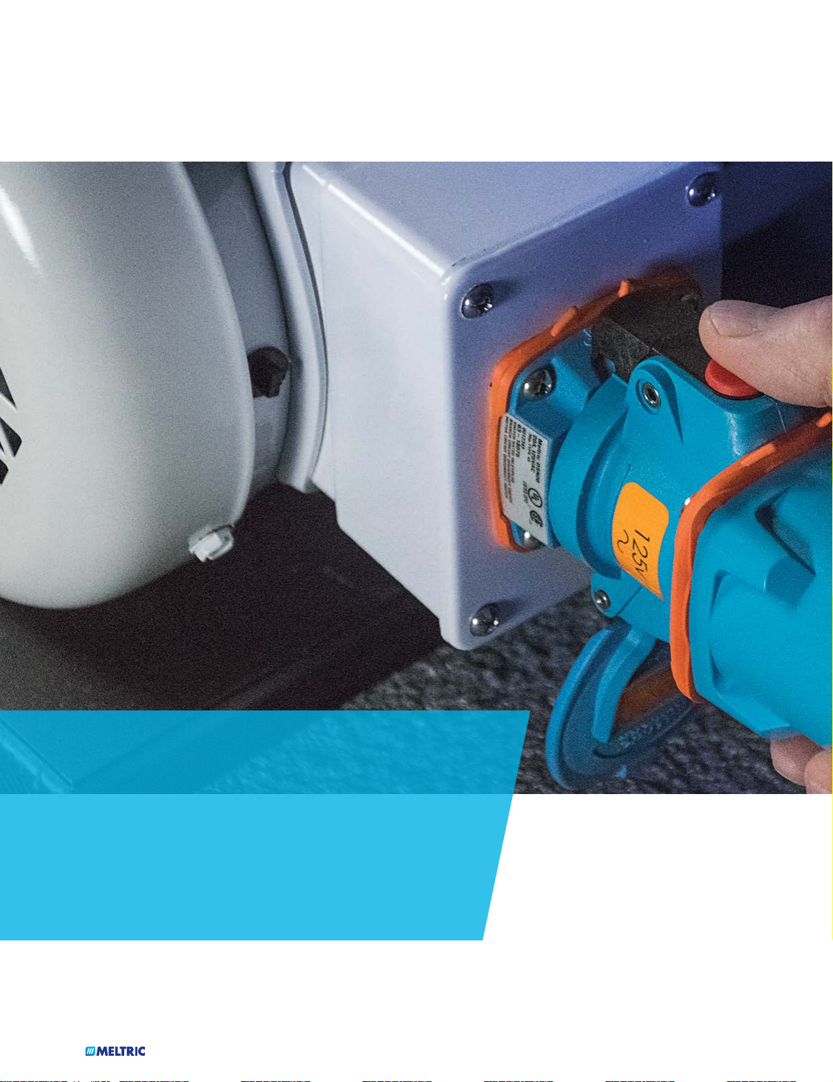
PRODUCT FEATURES
DECONTACTOR
Technology
®
OFF Button
Press to de-energize. Provides
push button circuit disconnection.
DSN
Operating
Instructions
Casing
Fiberglass reinforced thermoplastic
polyester material offers great
resistance to impact, corrosion and
harsh environmental conditions.
1
Spring Assisted Screw Terminals
Patented design assures “Tighten
and Forget” confidence.
Spring-Loaded Butt-Style Contacts
Ensures optimal contact force and
superior electrical performance over
thousands of operations.
Lid
Provides additional protection
in harsh environments.
General Ratings
Amperage
Voltage
Frequency
Horsepower
Short-Circuit
(Make & Withstand)
Environmental
20 to 150 A
600 VAC
50-400 Hz
.75 to 75 hp
100kA*
Type 4X/IP69/IP69K
Dead Front Safety Shutter
Assures safety by preventing
user access to live parts.
Lockout-Tagout Provisions
Allows plug to be easily locked
out and tagged. Optional
Padlock Pawl allows lockout/
tagout of the receptacle.
Silver-Nickel Contact Material
Solid silver-nickel contact surfaces
provide superior conductivity, durability
and corrosion resistance.
Highlighted Feature
Typical Device Labels
Meltric DSN30
30 A, TYPE 4X
10 HP, 480VAC
63-34043
SWITCH-RATED RECEPTACLE/CONNECTOR
MOTOR CIRCUIT DISCONNECT SWITCH
BRANCH CIRCUIT DISCONNECT SWITCH
LISTED 49B6
When the plug and receptacle
are latched together, the
circuit is connected.
2
Pressing the pawl breaks
the connection and opens
the circuit. The plug is
ejected to its rest position;
The contacts are now dead.
3
Rotating the ‘dead’ plug 30°
counterclockwise closes the
safety shutter and frees the
plug to be withdrawn from
the receptacle.
Temperature
DSN20, DSN30, DSN60: Testing was performed with RK1 current limiting fuses
*
sized at 400% or more of the highest full load motor ampacity associated with
the devices horsepower ratings.
DSN150: 100kA testing was performed with 225 A RK1 non-time delay Mersen
*
fuses. 10kA testing was performed with 400 A RK1 non-time delay Mersen fuses.
min -40°F/max 140°F
MELTRIC DSN Series Switch-Rated devices are
UL & CSA rated for “motor circuit” and “branch
circuit” disconnect switching – up to 75 hp and
up to 150 A.
Listings
Category UL CSA IEC
Plugs and Receptacles UL 1682 C22.2 No. 182.1 60309-1
Branch Circuit Disconnect
Switching (AC only)
Motor Circuit Disconnect
Switching (AC only)
CE ratings available upon request.
UL Subject 2682
(Performance tests from UL 98)
UL Subject 2682
(Performance tests from UL 98)
UL Subject 2682 60947-3, AC22, AC23
UL Subject 2682 60947-3, AC22, AC23
4
The plug and the receptacle are
separated. The safety shutter
prevents access to live parts.
To reconnect, insert
5
plug into receptacle,
rotate 30° clockwise, and
apply insertion force.
26
26
DSN20 Switch-Rated Plugs & Receptacles – 20 A
UL/CSA Ratings
• Max Amperage & Voltage
20 A, 600 VAC
• Switch-Rating (AC Only)
Branch Circuit & Motor Circuit
Disconnect Switching
• Horsepower Ratings
1Ø .75 hp
120V
240V
1Ø 2 hp
208V
3Ø 3 hp
240V
3Ø 3 hp
480V
3Ø 7.5 hp
600V
3Ø 7.5 hp
• Short Circuit Rating
100kA Close & Withstand
Testing was performed with 35 A RK1
non-time delay Mersen fuses.
10kA Close & Withstand
Testing was performed with 50 A RK1
non-time delay Mersen fuses.
• Environmental Ratings
Type 4X/IP69/IP69K*
* Also meets IP66/IP67 requirements
• Temperature Range
Min -40°F/Max 140°F
See pg 256 for temps below -15°F.
• Wiring Capacity
Min 14 AWG Max 12 AWG
Aux Contacts - 18 AWG prewired
• Certifications
UL 2682, UL 1682, CSA 182.1
Don’t forget to add installation
accessories to your order
!
Voltage Polarity
120V
120 208V
125V
125 250V
208V
208V
250V
250V
277V
277 480V
347 600V
480V
480V
600V
600V
1P+N+G 63-14165 63-18165
3P+N+G 63-14167 63-18167
1P+N+G 63-14075 63-18075
2P+N+G 63-14076 63-18076
1P+N+G 63-14045 63-18045
3P+N+G 63-14047 63-18047
3P+N+G 63-14147 63-18147
Receptacle
(female)
Inlet
(male)
North American UL/CSA Congurations
Part # Part #
Poly Poly
2P+G 63-14162 63-18162
3P+G 63-14163 63-18163
2P+G 63-14072 63-18072
3P+G 63-14073 63-18073
2P+G 63-14042 63-18042
3P+G 63-14043 63-18043
2P+G 63-14142 63-18142
3P+G 63-14143 63-18143
Main Options
See pages 233-242 for detailed
information on these options
!
27
Mushroom
Pawl
Padlock Pawl
Closed Lid
Configuration
Recommended for cord
applications to keep lid
tucked in to avoid damage.
Receptacle Options Suffix # Inlet Options Suffix #
With 2 Auxiliary/Pilot Contacts
Straight Insertion
Self-Ejecting Connector Release
Mushroom Pawl
Padlock Pawl
Padlockable Mushroom Pawl
Metal Pawl
Closed Lid Configuration
Notes: + Unlike other DSN & DS products, the DSN20 pilots are only on
the receptacle side and create a continuity loop that is completed when a
plug is connected to the receptacle.
Order Example: 480V DSN20 with padlock pawl
DSN20 Receptacle 3P+G = 63-14043-843
Recept # - 972+
Recept # - 352
Recept # - 354
Recept # - 375
Recept # - 843
Recept # - 375-843
Recept # - 824
Recept # - NC
Self-Ejecting Plug Release
With No Lockout Hole
Inlet # - 338
Inlet # - A155
INSTALLATION ACCESSORIES – SIZE 1
DSN20
DSNDSN
HANDLE w/NPT
1/2” 511P0N05 791P0N05L
Poly
HANDLESANGLES
3/4” 511P0N07 791P0N07L
1” 511P0N10 791P0N10L
Metal
For available cord grips, see page 165.
POLY HANDLE w/CORD GRIP
METAL HANDLE w/CORD GRIP
POLY HANDLE
POLY EXTENDED HANDLE
POLY ANGLED HANDLE
Part # Poly Part # Metal
Cable Range Part #
.350 - .520” 711P0BP6
.520 - .680” 711P0CP5
.680 - .980” 711P0DP4
.438 - .500" 791P0BS3L
.500 - .562" 791P0BS4L
.562 - .625" 791P0BS5L
.625 - .750" 791P0CS4L
.35 - .70” 511P0D18
.20 - .83” 511P0D21
.35 - .70” 511P6D18
POLY CONDUIT ENTRY w/NPT
BOXESMISCELLANEOUS ACCESSORIES
30° 1/2” 511B3N05
30° 3/4” 511B3N07
3
* 6.7 in
Part #
POLY WALL BOX w/ANGLE
70° 511C7000
3
* 82.0 in
Ground Bar 51AA089
POLY ANGLE WITH METAL BOX w/NPT
70° 1/2” 711C7N05
70° 3/4” 711C7N07
70° 1” 711C7N10
70° 1 1/4” 711C7N12
3
* 74.6 in
70° 1 1/2” 711C7N15
METAL BOX w/NPT
0° 1/2” 7T1F0N05
0° 3/4” 7T1F0N07
0° 1” 7T1F0N10
0° 1 1/4” 7T1F0N12
POLY ANGLE WITH METAL BOX w/NPT
* 29.8 in
30°
30° 3/4” 711C3N07
30° 1” 711C3N10
3
30° 1 1/4” 711C3N12
1/2”
711C3N05
NPT on top or bottom (if rotated). For other NPT configurations, contact customer service.
* Interior volume with
receptacle installed.
70° poly boxes are
not drilled. Contact
customer service
if factory drilled is
required.
* Interior volume with
receptacle installed.
* Interior volume with
receptacle installed.
* Interior volume with
receptacle installed.
POLY ANGLE
METAL ANGLE
MB Box 30° 511M3
70° 511M7
0° 591M0
FS/FD Box 30° 791M3FS
45° 591M4
* Base measures
approximately 4.2” x
2.7”. Due to the
variation in sizes of
FS boxes, please
verify that your FS
box matches our
dimensions, if not call
Customer Service for
other solutions.
FINGER DRAWPLATES
61-1A346
Set of Two (2)
Recommended for cord to cord assembly applications,
for easier connector closure.
PROTECTIVE INLET/PLUG CAP
61-1A426 For Inlets/Plugs Only.
PADLOCKABLE INLET/PLUG CAP
61-1A826 For Inlets/Plugs Only.
SCREWDRIVER FOR TERMINAL SCREWS
SD18 Klein 608-3 1/8” cabinet with 3” round shank.
EASY RETROFIT ADAPTER PLATES
see pg 162 Mount to existing boxes.
RECEPTACLE LOCKING PIN
LP-843 Requires Padlockable Pawl option (-843) on receptacle.
28
 Loading...