

Meltric DXN SERIES Instruction Manual
WARNING
A
COMPANY OF MARECHAL ELECTRIC
ENGLISH OPERATING INSTRUCTIONS
CONSIGNES D’UTILISATION
DX
DXN SERIES
©2020 MELTRIC Corporation. All rights reserved.
A manufacturer of products using Marechal technology
GENERAL
MELTRIC’s DXN Series plugs & receptacles are
designed and rated for use in hazardous environments
where explosive gases or dusts may be present.
The DXN receptacle has a dead front, which isolates
the supply contacts and prevents user exposure to live
parts. The receptacle’s safety shutter blocks access to
the contacts and can only be opened by DXN plugs
with compatible ratings and contact configurations.
There are inherent dangers
products. Failure to follow safety precautions can result in
serious injury or death. These instructions must be
followed to ensure the safe and proper installation,
operation and maintenance of the MELTRIC devices.
Before installation, disconnect all sources of power to
the circuit to eliminate the risk of electrical shock.
RATINGS & CERTIFICATIONS
To ensure the safe use of this product, the
installer must verify that the product is properly
rated for the application.
The amperage and voltage ratings are indicated on
the device labels. Some DXN devices are provided
with optional auxiliary contacts that make after and
break before the phase contacts. The ratings for
auxiliary contacts are shown in Table 1.
Hazardous Duty Ratings
Table 1 - Auxiliary Contact Ratings
Device 120VAC 240VAC 480VAC 600VAC
DXN30,60 5A* 5A* 5A* 5A* (550V max)
DXN plugs & receptacles have both ATEX and CSA
ratings for use in hazardous environments.
ATEX – Class 1 Zone 1 AEx ed IIC T6
This rating certifies the product for use in surface
(non-underground) applications where a high level
of protection is required and where the presence of
an explosive atmosphere of any type of gas or dust
is likely to occur. The associated maximum surface
temperature of the product is 85°C (185°F), at an
ambient temperature of 40°C (104°F).
associated with electrical
INSDXN N
CSA – Class 1 Division 2 Group A, B, C, D
Class 2 Division 2 Group E, F, G
This rating certifies the product for use in applications
where flammable gases, such as acetylene, hydrogen,
ethylene or propane, or dusts, such as magnesium,
coal or grain, may be present under abnormal conditions.
INSTALLATION
DXN’s must be used in conjunction with other
appropriately rated hazardous duty products
and must be installed by qualified electricians in
accordance with all applicable local and national
electrical codes.
Before starting, ensure that the power is off and verify
that the conductors meet the requirements of the
National Electric Code and are within the capacities of
the DXN terminals noted in Table 2.
Table 2 - Wiring Terminal Capacity1 - AWG
Main Contacts Aux. Contacts
Max Min Max
DXN20 10 16 N/A
DXN30 6 14 10
DXN60 4 10 10
1
Capacity is based on certification testing. Wire size
should be determined in accordance with the electrical code.
2
Auxiliary contacts are optional
General Notes & Precautions
1. Self-tapping screws are provided for use with
some polymeric accessories. High torque may
be required to drive them in and fully seat the
gasket/s. Once they are seated, care should be
taken in order to avoid over-tightening them against
the poly material. Poly Box with 70° Poly Angle
accessory: captive screws must be tightened to a
torque of 1.2Nm (10.62 in-lbs)
Metal Box with 70° Poly Angle accessory:
captive screws must be tightened to a torque
of 2.0Nm (17.7 in-lbs)
2. Wire strip lengths are indicated in Table 3.
Strip lengths for cable sheathing will depend
on the specific application. When used with
handles, the cable sheathing should extend
into the handle to ensure secure cord gripping.
Table 3 - Wire Strip Length - A (receptacle/inlet)
Inches mm
DXN20 - Main 0.50 / 0.50 12/12
DXN30 - Main 0.79/0.83 20/21
DXN30 - Aux. 0.67/0.67 17/17
DXN60 - Main 0.79/0.83 20/21
DXN60 - Aux 0.67/0.83 17/21
3. Wiring terminals are spring assisted to prevent
loosening due to wire strand settlement, vibration
& thermal cycling. They should not be over-tightened.
Appropriate tools and tightening torques are indicated
in Table 4. NOTICE: Do not back terminal screws
completely out.
Table 4 - Recommended Tightening Torques
Terminal Torque Flat Screwdriver
DXN20 7.1 in-lbs 1/8" precision tip
(Main Contacts) 10.6 in-lbs 3/16" precision tip
DXN30
(Aux. Contacts) 7.1 in-lbs 1/8" precision tip
DXN30
(Main Contacts) 17.7 in-lbs 3/16" precision tip
DXN60
(Aux. Contacts) 7.1 in-lbs 1/8" precision tip
DXN60
Assembly for In-line Plugs/Connectors
Do not overtighten terminal or self-tapping
screws. Tighten screws to the proper torque to ensure
a secure connection.
Flexible cord connected devices must be equipped with
a flexible cord listed for extra hard usage and terminated
with listed fittings in accordance with all applicable
local and national electrical codes. See table 6.
Type
Extra Hard
Usage
Table 6 - Flexible Cord
Max Nos of
Conductors
5 0.812 0.312
Flexible Cable Range
Max Øin Min Øin
DXN devices are rated to make and withstand short
circuit currents with appropriate fusing as indicated
in Table 5.
Table 5 - Short Circuit Make & Withstand Ratings
Device Rating Fuse Type*
DXN20 - 20A 25 kA@600VAC RK1 30A
DXN30 - 30A 25 kA@600VAC RK1 70A
2
DXN60 - 60A 25 kA@600VAC RK1 100A
* DXN20, 30 Ratings are based on testing with Mersen
Non-Time delay current limiting fuses
DXN60 Ratings are based on testing with Little Fuse
Non-Time delay current limiting fuses
* Note: Consult NEC for short circuit limits
When DXN’s are used as in-line connectors, finger
drawplates should be installed on both the receptacle
and plug in order to more easily provide the leverage
required to properly connect the devices.
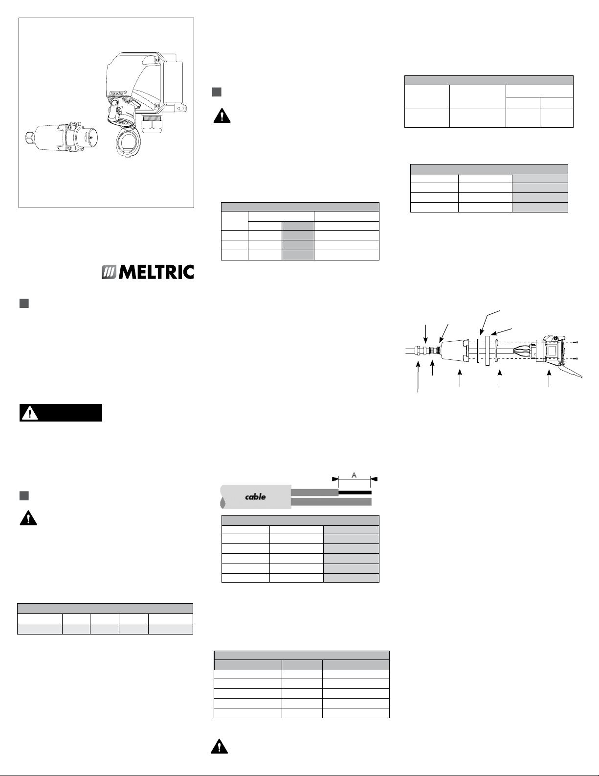
Finger Drawplate Gasket
DXN20 Remove Adhesive Liner
Finger Drawplate
Color-Coded
Gasket
Receptacle
(or Inlet)
Bushing
Strain
Relief
Compression
Nut
Threaded
Adapter
Handle
Loosely re-assemble the compression nut, bushing and
strain relief to the threaded adapter on the end of the
handle and insert the cable through it, the thin black
drawplate gasket and finger drawplate (if applicable),
and the color-coded gasket. Being mindful that the
strain relief must clamp on the cable sheath, strip the
cable sheath as required to provide a workable wire
length. Then strip the individual wires to the lengths
indicated in Table 3, and twist the strands of each
conductor together.
NOTICE: Back out the terminal screws on the receptacle
(or inlet) only far enough to allow the conductors to
pass, insert the conductors fully into their respective
terminals and tighten the terminal screws with a hand
screwdriver to the torque indicated in Table 4.
Verify that the cable jacket will extend beyond the
strain relief and into the handle. Assemble the
receptacle (or inlet), the color-coded gasket, the
finger drawplate, and the thin black finger drawplate
gasket to the handle with the four self-tapping screws
provided. NOTICE: Over-tightening the screws may
cause cracking in polymeric components. Adjust the
cable location so that it will not be under tension inside
the handle and tighten the compression nut to secure
the cable.
Short Circuit MELTRIC’s DXN Series Plugs &
Receptacles have short circuits make (close) and
withstand ratings up to 25kA when used with the
fusing shown in Table 5.
Assembly for Mounted Receptacles
(or Inlets)
In applications where DXN receptacles (or inlets) are
mounted to wall boxes, panels or other equipment,
optimal operation is achieved when the device
is installed with the pawl/latch at the top.
WARNING
NOTICE: If the device is mounted to a wall box, make
sure that appropriate hole plugs are securely tightened
in any unused connection holes.
Insert the cable or wires through the wall box and
cut to allow adequate length, strip the cable sheath,
as desired, strip the individual wires to the lengths
indicated in Table 3, and twist the strands of each
conductor together. Back out the terminal screws on
the receptacle (or inlet) far enough (but not completely)
to allow the conductors to pass, insert the conductors
fully into their respective terminals and tighten the
terminal screws to the torque indicated in Table 4, with
a hand screwdriver.
Assemble the receptacle (or inlet) and the color-coded
gasket to the box with appropriate hardware.
NOTICE: Over-tightening the screws may cause cracking
in polymeric components. Assemble the mating plug
(or receptacle) to the cord end as indicated in the
assembly instructions above for in-line connections,
except there will be no finger drawplate or associated
black gasket.
In cases where custom mounting is being performed
to an appropriate hazardous duty box or panel, the
clearance and mounting holes should be drilled as
indicated in the following diagram.
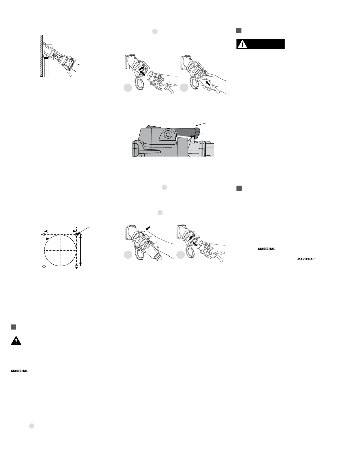
Hole Pattern for Custom Mounting
DXN20: 1.656" (42 mm)
DXN30: 1.890" (48 mm)
DXN20: 2.00"
(51mm)
DXN30: 2.25"
(56mm)
DXN60: 2.72"
(69mm)
DXN60: 2.171" (55.2 mm)
4 x Ø.196
(#9 or 5mm)
DXN20: 1.656"
(42mm)
DXN30: 1.890"
(48mm)
DXN60: 2.171"
(55.2mm)
NOTICE: In order to maintain IP66/IP67 protection
in custom installations, watertight seals must be used
under the heads of the four mounting bolts and they
must be retained by a lock washer and nut on the inside
of the box or panel. Alternatively, four blind holes can
be drilled and threaded to accommodate #8-32 x 5/8"
mounting screws. The hole depth must be sufficient to
achieve adequate gasket compression.
OPERATION
To ensure safe and reliable operation,
MELTRIC plugs and receptacles must be used
in accordance with their assigned ratings.
They can only be used in conjunction with mating
receptacles or plugs manufactured by MELTRIC or
another licensed producer of products bearing the
technology trademark.
MELTRIC plugs & receptacles are designed with
different keying arrangements, so that only plugs
and receptacles with compatible contact configurations and electrical ratings will mate with each other.
Connection
To connect a plug and receptacle, first depress the
pawl to open the lid on the receptacle, then orient
the plug 1. so that the red arrow on the outside of
the casing lines up with the red arrow just to the left
of the latch on the receptacle casing. Push the plug
partially into the receptacle until it hits a stop, then
rotate the plug in the clockwise direction until it hits
another stop after about 30° of rotation. At this point,
the circuit is still open. Push the plug straight into
the receptacle 2. until it becomes securely latched in
place. The connection is now made. For in-line connectors,
squeeze the drawplates on both sides of the device
together until the plug latches in place.
1
2
NOTICE: When making a connection, ensure that
the plug latch is secured behind the catch on the blue
pawl. A properly connected plug cannot be pulled out
of the receptacle.
Receptacle Plug/Inlet
Pawl
Latch
Disconnection
To break the connection, simply depress the pawl
as shown in figure 3. This will break the circuit and
eject the plug straight out to the rest, or off, position.
The plug contacts are de-energized at this point. To
remove the plug, rotate it counterclockwise (CCW)
(about 30°) until it releases from the receptacle as
shown in figure 4. Close and latch the lid on the
receptacle.
3
4
Achieving Watertightness Ratings
DXN’s have an IP66/IP67 rating for protection against
ingress of water, dust and other matter. IP66 provides
total protection against dust and water jets. IP67 adds
protection for temporary immersion in shallow water.
These ratings apply when the plug and receptacle
are mated. They also apply to the receptacle alone,
provided that its lid is latched in the closed position.
Optional plug caps are available for providing IP66/
IP67 protection on unmated plugs.
NOTICE: MELTRIC threaded handles come with
tapered style threads.The use of fitting seal tape is
recommended to maintain watertightness of all NPT
fittings and joints.
Lockout Provisions
All DXN plugs are provided with lockout provisions. To
lockout the plug, insert the locking device through the
hole provided in the casing. This will prevent the plug
from being able to be inserted into a receptacle.
Receptacles can be purchased with optional lockout
provisions. MELTRIC’s Locking Pin must be used to
lockout the receptacle. Close and latch the lid. Slide
MELTRIC’s Locking Pin through the hole provided in
the latch and place a padlock or other locking device
through one of the holes on the locking pin. This will
prevent the lid from being opened.
NOTICE: Attaching the receptacle locking device with
the lid open will not prevent the insertion of a plug.
Lockout is only accomplished when the lid is locked
closed.
MAINTENANCE
Before inspecting, repairing,
or maintaining MELTRIC
products, disconnect electrical power to the receptacle to
eliminate the risk of electrical shock. Any replacement of
DXN components must be performed under the control of
the manufacturer: MELTRIC Corporation.
MELTRIC products require little on-going maintenance.
However, it is a good practice to periodically perform
the following general inspections:
• Check the mounting screws for tightness.
• Verify that the weight of the cable is supported
by the strain relief mechanism and not by the
terminal connections.
• Check the IP gaskets for wear and resiliency.
Replace as required.
• Verify the electrical continuity of the ground circuit.
• Check the contact surfaces for cleanliness
and pitting.
Deposits of dust or similar foreign materials can be
rubbed off the male contacts with a clean cloth. Sprays
should not be used, as they tend to collect dirt. If
any significant pitting of the contacts or other serious
damage is observed, the device should be replaced.
Risk of electrostatic discharge: use a cloth slightly
soaked in soapy water for cleaning
MANUFACTURER’S RESPONSIBILITY
MELTRIC’s responsibility is strictly limited to the repair
or replacement of any product that does not conform
to the warranty specified in the purchase contract.
MELTRIC shall not be liable for any penalties or
consequential damages associated with the loss of
production, work, profit, or any other kind of financial loss
incurred by the customer.
MELTRIC Corporation shall not be held liable when
its products are used in conjunction with products not
bearing the technology trademark. The use of
MELTRIC products in conjunction with mating devices
that are not marked with the
technology
trademark shall void all warranties on the product.
MELTRIC Corporation is an ISO 9001 certified company.
Its products are designed, manufactured and rated in
accordance with applicable UL, CSA and IEC standards.
MELTRIC designs and manufactures its products in
accordance with Marechal keying standards established
to ensure intermatablility with similarly rated products
manufactured by Marechal Electric Group.
INSDXN N
 Loading...