

WARNING
A
ENGLISH OPERATING INSTRUCTIONS
DXA SERIES
©2020 MELTRIC Corporation. All rights reserved.
A manufacturer of products using MARECHAL® TECHNOLOGY
COMPANY OF MARECHAL ELECTRIC
GENERAL
Plugs, receptacles, connectors, inlets and
couplers are herein referred to as “devices”. DXA
DECONTACTOR™ devices are intended for
industrial applications in potentially explosive
atmospheres. In addition to IECEx and cCSAus
hazardous location ratings, they are cCSAus rated
for current interrupting duty and are HP rated for
use as a motor disconnecting means. They are
not intended to be used as the primary motor or
branch circuit disconnect switch.
The receptacle safety shutter blocks access to the
contacts and creates a dead front that prevents user
exposure to live parts. The opening/closing of the
safety shutter is controlled by the insertion/
withdrawal of a plug with compatible ratings and
contact congurations.
These instructions must
be followed to ensure the
proper installation, operation
and maintenance of the devices. There are inherant
dangers associated with electrical products and
failure to follow appropriate safety precautions can
result in serious injury or death. Be sure to
disconnect all sources of shock before starting
installation or maintenance.
• All metal parts must be connected to Ground.
A Ground connection is supplied with all
• These devices must be used in accordance
with their assigned current, voltage, IP and
Class/Division or Zone hazardous location.
• Any additional components used (e.g. cable
entry, adaptor, thread plug, etc.) must be
certied with a protection mode(s) and IP
ratings that are compatible with and maintain
the ratings of the device they are used with.
They must be installed according to the
manufacturer’s instructions.
• Respect recommended tightening torques
(see Table T2).
metal accessories.
INSDXA B
•
devices must be used with
INSTALLATION
complementary devices only. Connection to
devices not bearing genuine parts
will void the warranty and ratings.
• Certication requires that any replacement of
component(s) must be performed under the
control of the manufacturer MARECHAL
ELECTRIC S.A.S.
RATINGS & CERTIFICATIONS
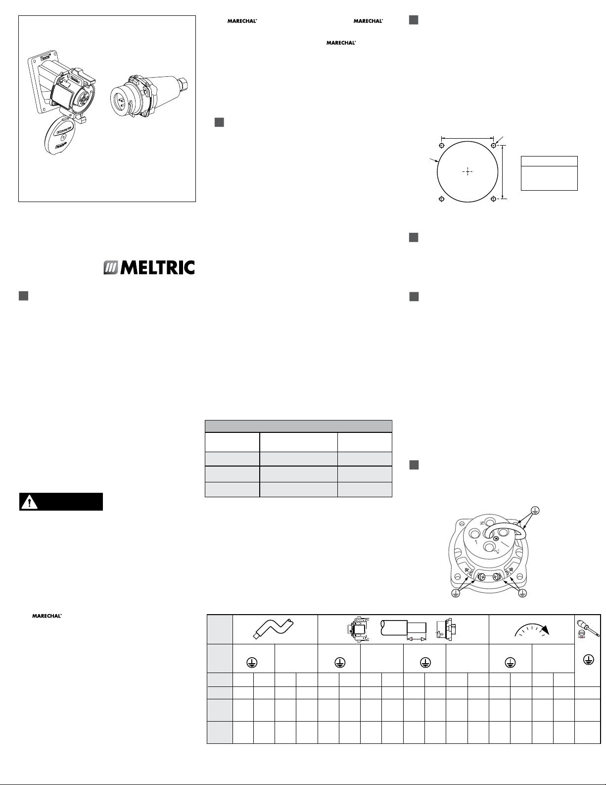
See Figure F3
•
Install the receptacle on a downward angle, with
the latching pawls at the top and at the bottom.
• Panel mounted devices must be assembled on a
“Ex e” increased safety enclosure according
to the drilling Figure F1.
Figure F1
A
4x
Ø
DXA devices have both cCSAus and IEC ratings
for use in hazardous environments.
Class I Zone 1 AEx de IIC T*Gb Zone 21 AEx tD T*Db
Class 1 Division 2 Group A, B, C, D
Class 2 Division 2 Group E, F, G
D
DXA1 inch mm
A 1.89 48
A
D 2.24 57
Ø
.196 (#9) 5
This NEC and CEC rating certies the product for
use in applications where ammable gases, such
as acetylene, hydrogen, ethylene or propane, or
dusts, such as magnesium, coal or grain, may be
WIRING
present under abnormal conditions.
• The contact terminals are spring-assisted to
Ex de IIC T*Gb Ex tb IIIC T* Db
This IEC rating certies the product for use in
surface (non-underground) applications where
a high level of protection is required and where
the presence of an explosive atmosphere of
any type of gas or dust is likely to occur. The
associated maximum surface temperature of
the product is 88°C (190°F), at an ambient
temperature of 60°C (140°F).
Short Circuit Make & Withstand Rating
DXA devices are rated to make and withstand short
circuit currents with appropriate fusing as indicated in
Table T1. Consult NEC for Short Circuit Limits.
T1 - Short Circuit Make & Withstanding Ratings
Device Rating Fuse Type*
DXA1 - 20A 25 kA @ 600 Vac RK1 30A
------------
------------
---------------
---------------
* DXA1, DXA3 Ratings are based on testing with Mersen Non-Time
delay. Current Limiting fuses.
DXA6, Ratings are based on testing with Little fuse Non-Time
delay. Current Limiting fuses.
--
--
--
--
prevent loosening due to strand settlement,
vibration or thermal cycling.
CONDUCTOR PREPARATION
• Remove an adequate length of cable outer
sheath according to the accessory used.
• Ensure that the cable sheathing extends
through the cord grip into the handle or box as
required to achieve the intended sealing and
cord gripping performance.
• Strip conductor insulation to the length
indicated in Table T2.
• (Do not back terminal screws completely out).
Fully insert the conductor and tighten the terminal
screws to the torque indicated in Table T2.
GROUNDING CONNECTIONS
DXA1 metal casings are equipped with 3
ground terminals as shown in Figure F2.
Figure F2
Auxiliary Contact Ratings
Some DXA devices are provided with optional
auxiliary contacts that make after and break before
the phase contacts. The ratings for auxiliary
contacts are shown in Table T2.
marechal
T2
1-2-3-N
A-B A-B A-B A-B
Device mm1 AWG mm2 AWG mm inch mm inch mm inch mm inch Nm inch-lbs Nm inch-lbs
DXA1 1.5-6 16-10 -- -- 12 0.50 -- -- 12 0.50 -- -- 0.8 7.1 -- --
-------- -- -- -- -- -- -- -- -- -- -- -- -- -- -- -- --
--------
-- -- -- -- -- -- -- -- -- -- -- -- -- -- -- --
1
Wire capacity is based on certification testing. Wire size should be determined in accordance with the electrical code.
2
A device intended for flexible connections must be equipped with a flexible cord listed for extra-hard usage and terminated with listed fittings in accordance with all applicable local and national electrical codes
1 2
Auxiliary
1 2
1-2-3-N Auxiliary 1-2-3-N Auxiliary 1-2-3-N Auxiliary
3 (Philips)
3x0.75 mm
1/8"
----------
----------
• One ground terminal is factory-wired to the
ground contact. This wire must not be removed
as it also grounds the second and third ground
terminals.
• Second ground terminal is used for the
ground conductor.
• Third ground terminal is used to ground the
accessory (box, handle, angle).
COLOR CODED GASKETS
Insert the color-coded gaskets between the device
and its rear accessory (box, handle, angle).
The two protrusions on the gasket must be
positioned on the latch sides of the receptacle/
connector and on the catch side for the inlet/plug.
This gasket is needed to maintain the IP rating.
If used in conjunction with nger draw plates, the
gasket must be between the receptacle (or inlet).
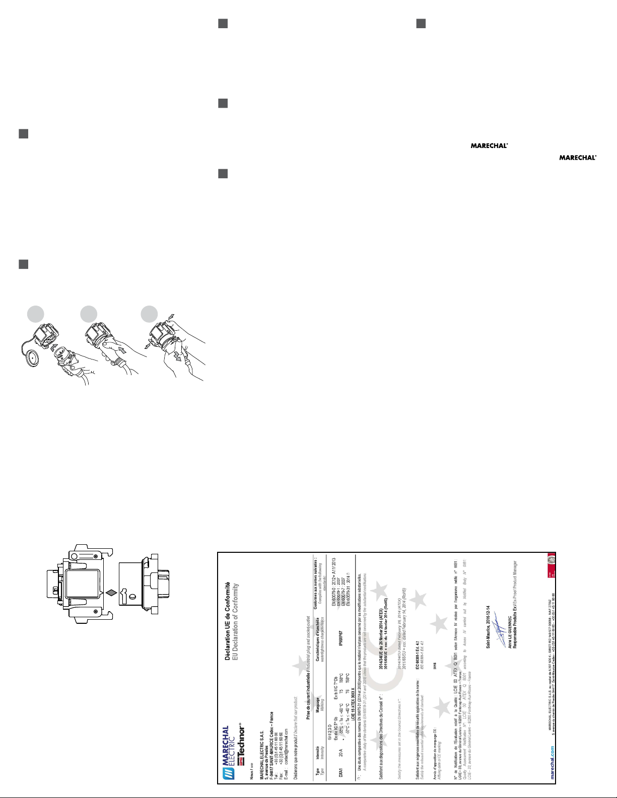
OPERATION
See Figure F3
F3
1 2 3
1
2 3
CONNECTION LOCKING (OPTION)
With the plug fully mated to the receptacle, insert the
metal locking pin through the hole in the pawl on the
receptacle and place a padlock or other locking
device through one of the holes on locking pin.
This will prevent unintended disconnection.
PLUG LOCKOUT (OPTION)
• To prevent the plug from being inserted
into a receptacle, place a padlock or other
lockout device through the hole provided
in the plug casing.
MAINTENANCE
• IEC/EN 60079-17 & UL 60079-17standard:
Explosive atmospheres – Part 17: “Electrical
installations inspection and maintenance”,
foresees very strict requirements regarding
the maintenance of electric installations which
must be imperatively respected.
• Ensure that the xing screws, caps and cable
glands are tight.
• Verify that the weight of the cable is supported
by the strain relief mechanism and not by the
terminal connections.
MANUFACTURER’S RESPONSIBILITY
MELTRIC’s responsibility is strictly limited to the
repair or replacement of any product that does not
conform to the warranty specied in the purchase
contract. MELTRIC shall not be liable for any
penalties or consequential damages associated with
the loss of production, work, prot or any nancial
loss incurred by the customer.
MELTRIC Corporation shall not be held liable when
its products are used in conjunction with products
not bearing the
The devices that are not marked with the
technology trademark.
technology trademark shall void all warranties on
the product and listing is invalidated.
MELTRIC Corporation is an ISO 9001 certied
company. Its products are designed, manufactured
and rated in accordance with applicable UL, CSA
and IEC standards. MELTRIC designs and
manufactures its products in accordance with
Marechal keying standards established to ensure
intermatablility with similarly rated products
manufactured by Marechal Electric Group.
• Only devices with compatible contact
congurations and electrical ratings will
mate with each other.
• The receptacle is shielded by a protective
lid held in the closed position by two latches.
Depress the latches to release the lid.
• To connect, align the arrow heads on the
housings (see Figure F4), insert the device
and turn it clockwise until it hits a stop. The
device is in the rest position and the circuit
remains open.
Figure F4
marechal
• Check the cleanliness of contacts.
• To inspect the contacts, depress the springloaded
ejection ring on two opposite points. The safety
shutter can then be rotated clockwise to inspect
contact tips.
• Any deposit can be rubbed off with a clean
cloth or compressed air.
• In case of damage, contact your supplier to
have them replaced by the manufacturer.
• Do not forget to re-lock the safety shutter
after inspection.
• Inspect periodically IP gaskets for wear and
resilience. Replace as required.
• Check regularly the continuity of the ground
circuit by electric tests.
• Push the device straight into the complementary
device until it becomes securely latched.
• To disconnect, depress the latching pawls
simultaneously. The device returns to its rest
position and the circuit is open.
• To remove the device, turn it counter-clockwise
and pull. Replace receptacle lid.
INSDXA B
 Loading...