

WARNING
ENGLISH OPERATING INSTRUCTIONS
CONSIGNES D’UTILISATION
DX
DX
©2018 MELTRIC Corporation. All rights reserved.
A manufacturer of products using Marechal technology
GENERAL
MELTRIC’s DX Series plugs & receptacles are designed for industrial use according to IEC/EN 60309-
1. They are designed for applications where rugged
metal construction is required and when there is a
need for amperages up to 100A. Follow the instructions below to ensure the proper installation and use of
this product.
There are inherent
dangers associated with
electrical products. Failure to follow safety precautions can result in serious injury or death. These
instructions must be followed to ensure the safe and
proper installation, operation and maintenance of the
MELTRIC devices. Before installation, disconnect all
sources of power to the circuit to eliminate the risk
of electrical shock.
RATINGS & CERTIFICATIONS
To ensure the safe use of this product,
the installer must verify that the product
is properly rated for the application.
The amperage, voltage, temperature, and environmental ratings are indicated on the product label.
MELTRIC’s DX Series plugs and receptacles are
ATEX-rated in accordance with the European ATEX
Directive (94/9/EC).
The ATEX rating certies the product for use in surface
(non-underground) applications where a high level of
protection is required and where the presence of an
explosive atmosphere is likely to occur (Zone 1 and
Zone 21 environments). It’s suitable for installation in
areas that may contain ammable gases, vapors, mists,
or dusts, including subdivision C gases. The product possesses explosion protection and is provided
with ‘e’ increased safety in the conductor termination
area and ‘d’ explosion proof chambers for making
and breaking electrical current that can withstand the
pressure of internal ignition. It also can prevent arcs,
ame or other ignition events from being communicated to the surrounding atmosphere. The maximum
allowable surface temperature of the product is 85°C
(185°F) at 40°C (104°F) ambient.
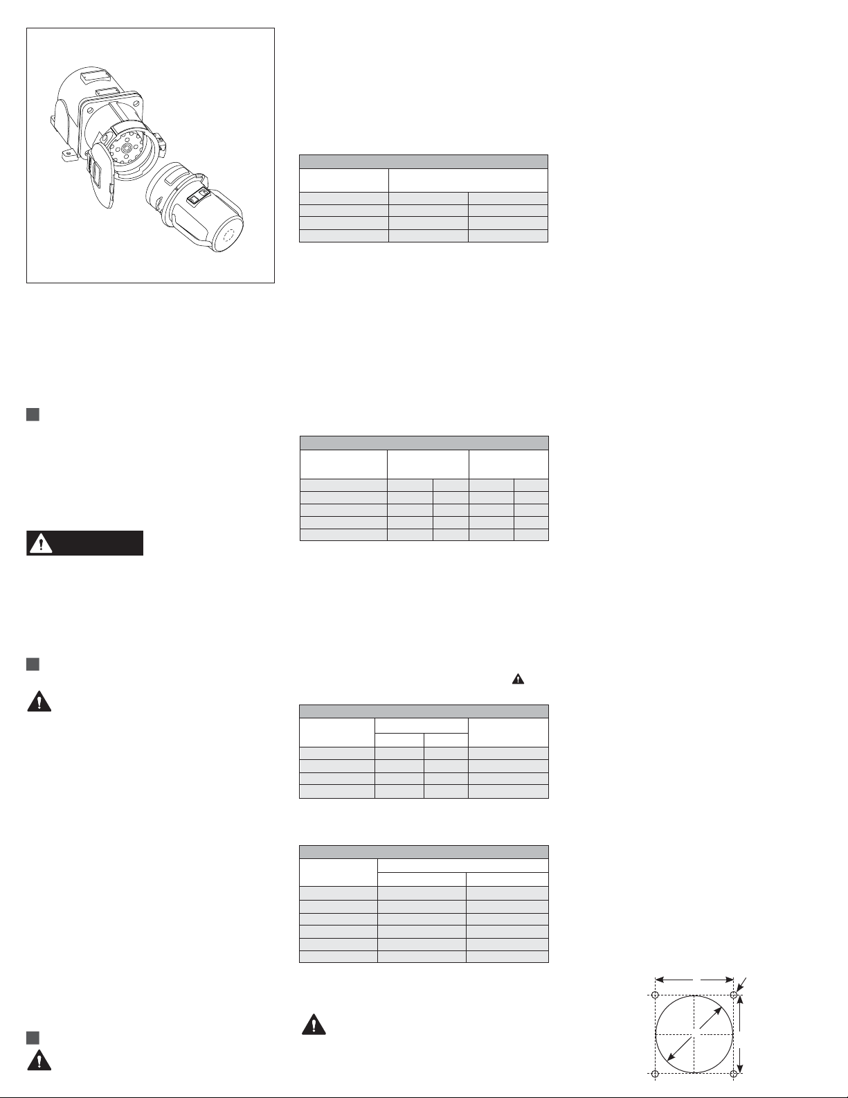
INSTALLATION
DX Series devices must be used in conjunction
INSDX I
with other appropriately rated hazardous duty prod-
ucts and must be installed by qualied electricians
and in accordance with all applicable local and national electrical codes.
Before installing, verify that (1) the power is off, (2)
the product ratings are appropriate for the application,
and (3) the conductors meet the requirements of the
National Electric Code and are within the capacities of
the DX terminals noted in Table 1.
Table 1 - Wiring Terminal Capacity1 (in AWG)
Main Contacts
Device Min Max
DX1 - 20A 14 8
DX3 - 32A 14 8
DX6 - 63A 6 1
DX9 - 125A 2 2/0
1
Capacity is based on THHN wire sizes
General Installation Notes & Precautions
1. Wire strip lengths are indicated in Table 2. Strip
lengths for cable sheathing will depend on the
specic application. When used with handles, the
cable sheathing should extend into the handle to
ensure secure cord gripping.
Table 2 - Wire Strip Length – Dimension A
Phase & Neutral Earth
Conductor Conductor
Device Inches mm Inches mm
DX1 20A 0.79 20 0.79 20
DX3 32A 0.79 20 0.79 20
DX6 63A 1 1/16 27 1 3/16 30
DX9 125A 1 3/8 35 1 3/16 30
2. Wiring terminals are spring assisted to prevent
loosening due to wire strand settlement, vibration and thermal cycling. NOTICE: They should
not be overtightened. Appropriate tools and tightening torques are indicated in Table 3. Wiring
must be made according to applicable national
installation standards. Follow all conductor coding
and terminal marking standards. Back out terminal screws far enough (but not completely) to
allow a complete insertion of conductors. All
metal parts must be connected to Earth ground.
Table 3 - Terminal Screw Tightening Torques
Torque Required Flat
Device/Contact In. lb N-m Screwdriver
DX1 (20 A) 11 1.3 4 x 1 mm
DX3 (32 A) 11 1.3 4 x 1 mm
DX6 (63 A) 26 3 6 x 1.2 mm
DX9 (125 A) 53 6 6 x 1.2 mm
3. Only handles with supplied cord grips may be
used in order to maintain proper ATEX ratings.
Table 4 - Cord Grip Cable Tightening Range
Sufx# Range
Inches mm
-20M 0.31 - 0.51 8 - 13 mm
-25M 0.35 - 0.63 9 - 16 mm
-32M 0.47 - 0.83 12 - 21 mm
-40M 0.63 - 1.06 16 - 27 mm
-50M 0.91 - 1.38 23 - 35 mm
-63M 1.42 - 1.89 36 - 48 mm
Assembly for In-line Plugs/Connectors
Do not overtighten terminal or self-tapping
screws. Tighten screws to the proper torque
to ensure a secure connection. Insert cable
through handle (connector) or remove plug interior
molding from the front and insert cable through plug
body (plug/inlet). Strip the cable sheath as required
to provide a workable wire length while being aware
that the strain relief must clamp on the cable sheath.
Strip the individual wires to the lengths indicated
in Table 2 and twist the strands of each conductor
together. Back out the terminal screws on the receptacle (or inlet) only far enough to allow the conductors
to pass. Insert the conductors fully into their respective terminals and tighten the terminal screws with a hand
screwdriver to the torque indicated in Table 3. Verify that
the cable jacket will extend beyond the strain relief
and into the handle. Assemble the receptacle (or
connector) to the handle. Adjust the cable location
so that it will not be under tension inside the handle
and tighten the compression nut to secure the cable.
After assembly, the cable sheath must extend into the
handle. Assemble handle with supplied screws and
gasket (connector) or assemble interior molding into
plug casing (plug) and tighten cord grip (cable gland).
Cord grip cable tightening ranges are indicated in
Table 4. While clamping or anchoring, the conductors inside the handle must not be tight.
NOTICE: For a proper clamping the use of PVC
cables is not recommended.
Assembly for Mounted Receptacles (or Inlets)
In applications where DX receptacles are mounted
to wall boxes, panels or other equipment, optimal
operation is achieved when the device is installed with
the pawl latch at the top. (However, if the receptacle
is mounted to the MELTRIC surface box accessory,
the pawl latch will be on the bottom due to the vertical
orientation of the box/receptacle.)
NOTICE: if the DX device is mounted to a wall box,
make sure that hole plugs are securely tightened in
any unused connection holes.
All wires brought into a MELTRIC wall box or hazardous duty box/panel must be connected in accordance
with all approved local and national electrical codes
based on the rating of the hazardous location environment. The individual wire insulators should be
stripped off base on the dimensions given in Table 2.
Then, twist the strands of each conductor together.
Back out the terminal screws on the receptacle (or
inlet) far enough to allow the conductors to pass
and insert the conductors fully into their respective
terminals. Tighten the terminal screws with a hand
screwdriver to the torque indicated in Table 3. Assemble the receptacle (or inlet) on adapter or wall
box, using gaskets and screws provided. When not
in use, ensure that the protective cap or lid supplied is
properly secured to prevent environmental contamination. Assemble the mating plug (or inlet) to the cord
end as indicated in the assembly instructions for inline connections. In cases where custom mounting is
being performed to an appropriate hazardous duty box
or panel, the clearance and mounting holes should be
drilled as indicated in the next section, Hole Pattern
for Custom Mounting.
Hole Pattern for Custom Mounting
NOTICE: In order to maintain IP65 protection in cus-
tom installations, watertight seals must be used under
the heads of the four mounting bolts and they must
be retained by a lock washer and nut on the inside of
the box or panel. The hole depth must be sufcient to
achieve adequate gasket compression. Refer to the
following instructions and drawing for the assembly of
the plug/receptacles or inlets on ‘e’ increased safety
boxes, panels or enclosures:
B
A
C
B
WARNING
Table 5 - Custom Mounting Dimensions
A B C
Device Inches mm Inches mm Inches mm
DX1 4.3 109 3.62 92 1/4 M6
DX3 4.3 109 3.62 92 1/4 M6
DX6 5.9 150 4.80 122 5/16 M8
DX9 5.9 150 4.80 122 5/16 M8
OPERATION
To ensure a safe and reliable operation,
MELTRIC’s DX Series plugs & receptacles
must be used in accordance with their assigned electrical and Ex ratings, as well as their IP
ratings according to IEC/EN 60309-1.
They can only be used in conjunction with mating
receptacles or plugs manufactured by MELTRIC or
another licensed producer of products bearing the
technology trademark.
MELTRIC plugs & receptacles are designed with
different keying arrangements so that only plugs and receptacles with compatible contact congurations and
electrical ratings will mate with each other. When not
in use, the receptacle is shielded by a protective lid to
prevent the entry of dust and moisture. This is held in
the closed position by a latch.
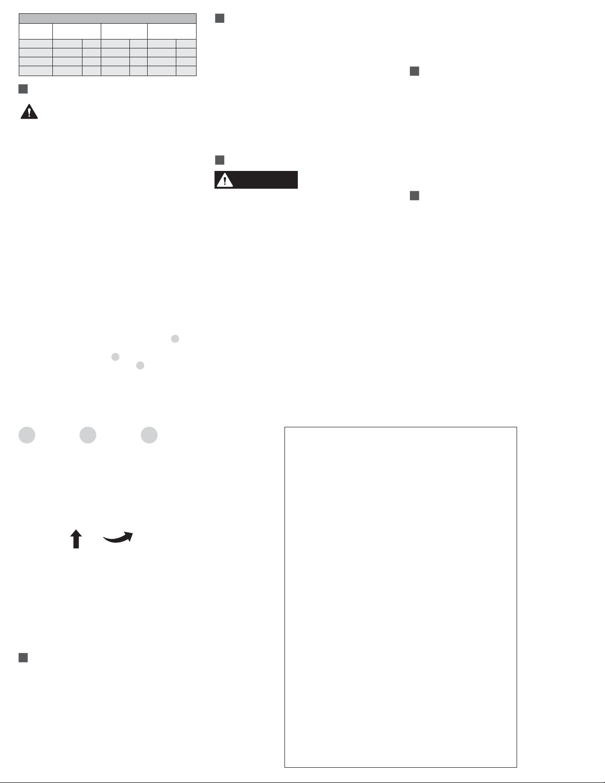
Connection
To connect a plug and receptacle, rst depress the
pawl to release the lid on the receptacle, then orient
the plug so that the colored mark on the outside ridge
of the plug casing lines up with the Ø or unlock symbol on the receptacle casing. Push the plug in partially into the receptacle until it hits a stop Fig. 1. At
this point, the circuit is still open. To close the circuit,
turn the plug clockwise Fig. 2 until it hits another
stop after about 30° of rotation. Fig 3.
NOTICE: When making a connection, ensure that
the plug latch is secured behind the catch on the
pawl. A properly connected plug cannot be pulled out
of the receptacle.
LOCKOUT PROVISIONS
All DX receptacles are provided with padlocking
lockout provisions. To operate, insert the 3 hole shaft
through the hole under the receptacle pawl. Place
user supplied lock or lockout hasp through one of the
holes. This system may be used to lock mated devices together to prevent unintended disconnection or
to prevent mating of devices by locking the receptacle
lid closed.
NOTICE: Attaching the receptacle locking device with
the lid open will not prevent the insertion of a plug.
Lockout is only accomplished when the lid is locked
closed.
MAINTENANCE
Before inspecting, repairing,
or maintaining MELTRIC
products, disconnect electrical power to the receptacle to eliminate the risk of electrical shock. Any
replacement of DX components must be performed
under the control of the manufacturer: MELTRIC
Corporation.
MELTRIC products require little on-going maintenance. However, it is a good practice to periodically
perform the following general inspections:
• Check the mounting screws for tightness.
• Verify that the weight of the cable is supported
by the strain relief mechanism and not by the
terminal connections.
• Check the IP gaskets for wear and resiliency.
Replace as required.
• Verify the electrical continuity of the ground circuit.
• Check the inlet contact surfaces for cleanliness
and pitting.
Deposits of dust or similar foreign materials can be
rubbed off the contacts with a clean cloth. Sprays
should not be used, as they tend to collect dirt. If
any signicant pitting of the contacts or other serious
damage is observed, the device should be replaced.
DECLARATION OF CONFORMITY
DX Series plugs/receptacles use the
technology. They have been designed, manufactured
and controlled in a strict respect of the relevant international and European standards, laws and directives,
and particularly of the European ATEX Directive.
They bear the CE marking whenever applicable.
They also bear the markings of their explosion-proof (Ex)
classication.
Note: The CE marking does not apply to spare parts
and components supplied separately.
MANUFACTURER’S RESPONSIBILITY
MELTRIC’s responsibility is strictly limited to the
repair or replacement of any product that does not
conform to the warranty specied in the purchase
contract. MELTRIC shall not be liable for any penalties or consequential damages associated with the loss
of production, work, prot or any nancial loss incurred by
the customer.
MELTRIC Corporation shall not be held liable when
its products are used in conjunction with products not
bearing the
use of MELTRIC products in conjunction with mating
devices that are not marked with the
technology trademark. The
technology trademark shall void all warranties on the
product.
MELTRIC Corporation is an ISO 9001 certied company. Its
products are designed, manufactured and rated in accordance
with applicable UL, CSA and IEC standards. MELTRIC designs
and manufactures its products in accordance with Marechal keying standards established to ensure intermateablility with similarly
rated products manufactured by Marechal Electric Group.
1
2 3
Disconnection
To break the connection, depress the pawl and rotate
the plug counterclockwise about 30° until it hits a
stop. At this point, the electrical circuit is open. To
fully remove the plug, depress the pawl and pull the
device straight out. The self-closing lids on the receptacles may need to be manually latched to ensure
optimal environmental ratings.
Achieving Rated Watertightness
MELTRIC’s DX Series plugs & receptacles have an
IP65 rating for protection against ingress of water,
dust and other matter. IP65 provides total protection
against dust and water jets. These ratings apply when
the plug and receptacle are mated. They also apply
to the receptacle alone, provided that its lid is latched
in the closed position. Optional plug caps are available for providing IP65 protection on unmated plugs.
INSDX I
 Loading...