

OPERATING INSTRUCTIONS
WARNING
DSDC
INSDSDC D
Meltric Corporation / 4640 Ironwood Drive Franklin, WI 53132
Tel. : 800 433 7642 / Fax : 414 817 6161 / e-mail : mail@meltric.com
A manufacturer of products using Marechal technology
meltric.com
GENERAL
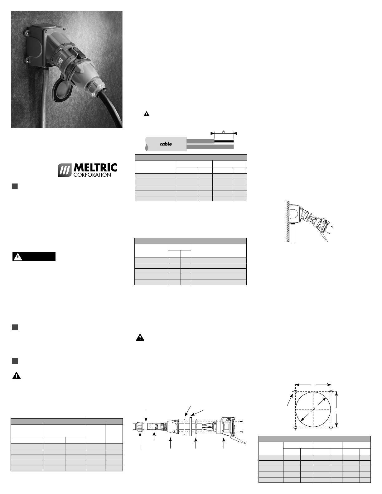
Meltric’s DSDC Series industrial plugs and
receptacles provide safe and robust connections
for direct current applications up to 750 VDC. The
DSDC’s spring-loaded, silver-nickel, butt contacts and
dead front construction provide more consistent and
reliable connections and significant improvements in
operator safety. Please follow the instructions below
to ensure the proper installation and use of
the product.
There are inherent dangers
products. Failure to follow safety precautions can
result in serious injury or death. These instructions
must be followed to ensure the safe and proper
installation, operation and maintenance of the
Meltric devices. DSDC plugs and receptacles are
not designed for current interrupting. Standard
locking features should be used to prevent accidental
connection or disconnection under load. Before
installation, disconnect all sources of power to the
circuit to eliminate the risk of electrical shock.
RATINGS
These products are manufactured and rated in
compliance with applicable UL and CSA standards.
The products ratings are indicated on the device labels.
INSTALLATION
These products should be installed by qualified
personnel in accordance with all applicable
local and national electrical codes.
Before installing, verify that the power is off, that the
product ratings are appropriate for the application, and
that the conductors meet code requirements and are
within the capacities of the terminals noted in Table 1.
Table 1 - Wiring Terminal Capacity1 (in AWG) Cable Range OD
Main
Contacts
Device Min Max
DSDC1 14 8 .30 1.380
DSDC3 14 6 .51 1.380
DSDC6 10 2 .50 1.812
DSDC9 6 2/0 .50 1.812
DSDC2 4 4/0
1
Capacity is based on THHN wire sizes
2
2/0 AWG if part number does not include the ‘A06’ suffix.
associated with electrical
Min Max
2
.87 2.400
General Notes & Precautions
1. Self-tapping screws are provided for use with
some polymeric accessories. High torque may
be required to drive them in. NOTICE: Once
they are seated, care should be taken in order to
avoid over-tightening them against the plastic material.
2. Various handles and cord grip options may be
used. These instructions are based on handles
provided with integral multi-layer bushing cord grips.
3. Wire strip lengths are indicated in Table 2. Strip
lengths for cable sheathing will depend on the
specific application. When used with handles, the
cable sheathing should extend into the handle to
ensure secure cord gripping.
4. For some applications a jumper may be
supplied between terminals and should not be
removed.
Table 2 - Wire Strip Lengths – Dimensions A
Receptacle Plug/Inlet
Device/Contact Inches mm Inches mm
DSDC1 Phase 7/16 10 3/4 19
DSDC3 Phase 9/16 14 7/8 22
DSDC6 Phase 15/16 24 15/16 24
DSDC9 Phase 1 3/16 30 1 3/16 30
DSDC2 Phase 1 3/16 30 1 3/16 30
5. Wiring terminals are spring assisted to prevent
loosening due to stand settlement, vibration and
thermal cycling. They should not be over-tightened.
Appropriate tools and tightening torques are
indicated in Table 3.
Table 3 - Terminal Screw Tightening Torques
Torque Required Screwdriver
Device/Contact in-lbs N-m or Allen Wrench
DSDC1 Phase 15 1.7 4 mm or 3/16” precision tip
DSDC3 Phase 25 2.8 5 mm or 3/16” precision tip
DSDC6 Phase 48 5.4 4 mm hex head
DSDC9 Phase 90 10.2 4 mm hex head
DSDC2 Phase 110 12.4 5 mm hex head
6. NOTICE: Proper steps must be taken to maintain
watertightness at NPT fittings on the plug handles
or at the junction box. Use of sealer tape is
recommended.
Assembly for In-Line Connections
Do not overtighten terminal or self-tapping
screws. Tighten screws to the proper torque to
ensure a secure connection.
When these products are used as in-line connectors,
finger drawplates (or a drawbar mechanism) should
be installed on both the receptacle and plug in order
for the user to more easily provide the leverage
required to connect the device. On the larger sized
DSDC9 and DSDC2, the finger drawplates are not
needed because an easy closing mechanism is
provided as standard.
Bushing
Compression
Nut
Strain
Relief
Handle
Finger Drawplate Gasket
Finger Drawplate
Color-Coded
Gasket
Receptacle
(or Inlet)
Adjust the bushing diameter to fit the cable by
removing inner sections of it as required. Insert the
bushing into the strain relief, then insert the assembly
into the handle and loosely install the compression
nut. Insert the cable through the handle, the thin
black drawplate gasket and finger drawplate (if
applicable) and the color coded gasket. Strip the
cable sheath to provide a workable wire length,
being mindful that the sheath must extend into the
handle to achieve a secure cord grip. Then strip the
individual wires to the lengths indicated in Table 2
and twist the strands of each conductor together.
Back out the terminal screws on the receptacle (or
inlet) far enough (but not completely) to allow the
conductors to pass, insert the conductors fully into
their respective terminals and tighten the terminal
screws with the appropriate tool to the torque
indicated in Table 3.
Verify that the cable sheath extends beyond the
strain relief and into the handle. Assemble the
receptacle (or inlet), the color coded gasket, the
finger drawplate, and the thin black drawplate gasket
to the handle with the four self-tapping screws
provided. Adjust the cable location so that it will not
be under tension inside the handle and tighten the
compression nut to secure the cable.
Assembly for Mounted Receptacles (or Inlets)
In applications where the receptacles (or inlets) are
mounted to wall boxes, panels or other equipment,
optimal operation is achieved when the device is
installed with the latch at the top and with the force
of the cable being exerted in a downward direction
opposite the latch.
Insert the cable or wires through the wall box and
cut to allow adequate length, strip the cable sheath
as desired, strip the individual wires to the lengths
indicated in Table 2, and twist the strands of each
conductor together. Back out the terminal screws on
the receptacle (or inlet) far enough (but not completely)
to allow the conductors to pass, insert the conductors
fully into their respective terminals and hand tighten
the terminal screws to the torque indicated in Table 3.
Assemble the receptacle (or inlet) and the color-coded
gasket to the box with the appropriate hardware.
Assemble the mating plug (or receptacle) to the cord
end as indicated in the assembly instructions above
for in-line connections, except there will be no finger
drawplate or associated black gasket.
Hole Pattern for Custom Mounting
In applications where custom mounting to a panel
or box is desired, the clearance and mounting holes
should be drilled as indicated in the following diagram
and Table 4.
B
C
Table 4 - Custom Mounting Dimensions
‘A’ ‘B’ ‘C’
Model Inches mm Inches mm Inches mm
DSDC1 2.25 57 1.89 48 .19 5.0
DSDC3 2.50 64 2.17 55 .19 5.0
DSDC6 3.25 83 2.59 66 .22 5.5
DSDC9 4.00 102 3.20 81 .22 5.5
DSDC2 4.50 114 3.86 98 .28 7.0
A
B

The DSDC series offers a NEMA 3R or IP54/IP55
WARNING
protection standard. NOTICE: An option for Type 4X
or IP 66 & 67 protection is available in custom
installations. Watertight seals should be used under
the heads of the four mounting bolts and they must
be retained by a lock washer and nut on the inside of
the box or panel. Alternatively, four blind holes may
be drilled and threaded to accomodate the mounting
screws, provided that the hole depth is sufficient to
achieve adequate gasket compression.
OPERATION
To ensure safe and reliable operation Meltric
plugs and receptacles must be used in
accordance with their assigned ratings.
They can only be used in conjunction with mating
receptacles or plugs manufactured by Meltric or
another licensed producer of products bearing the
TM technology trademark.
Meltric plugs & receptacles are designed with
different keying arrangements, so that only plugs and
receptacles with compatible contact configurations
and electrical ratings will mate with each other.
Factory jumpers are installed on devices
intended for applications of 600VDC and
750VDC. The figure below shows the location of
these jumpers, DO NOT REMOVE them.
As an added safety feature, the DSDC2 is provided
with a “locking pawl” to prevent any unintended
connections. To mate the devices, loosen the thumb
screw on the pawl, and follow steps 1 and 2. On the
DSDC9 and DSDC2 devices, an integral mechanism
provides easy connection of the plug to the receptacle.
With the DSDC9 or DSDC2 plug partially inserted
and rotated 30° so that it is positioned for connection,
place the wire clamps around the bolt heads as
shown in figure 3.
3
Wire clamp
around bolthead
To pull the plug into the receptacle, simply push
the handles back along the side of the receptacle
and then push the plug into the receptacle until the
plug is latched in place, as shown in figure 4. On
the DSDC2, tighten the thumb screw on the pawl to
prevent any unintended disconnection. A locking
device should be used when the devices are mated.
4
by inserting a locking device through the hole
provided in the pawl after the plug and receptacle
have been connected.
To lockout the plug, insert a locking device through
the hole provided in the casing. This will prevent the
plug from being inserted into a receptacle.
To lockout the receptacle, close and latch the lid
and then insert the locking device through the hole
provided in the pawl. This will prevent the lid from
being opened for the insertion of a plug.
MAINTENANCE
Before inspecting, repairing, or
maintaining Meltric products,
disconnect electrical power to the receptacle to
eliminate the risk of electrical shock.
Meltric products require little on-going maintenance.
However, it is a good practice to periodically perform
the following general inspections:
• Check the mounting screws for tightness.
• Verify that the weight of the cable is supported
by the strain relief mechanism and not by the
terminal connections.
• Check the IP gaskets for wear and resiliency.
Replace as required.
• Verify the electrical continuity of the ground circuit.
• Check the contact surfaces for cleanliness and pitting.
Dual Circuit DC Wiring Instruction for
Non-Load Break Applications
Some applications require connections with 2
separate DC circuits. This requires 4 contacts
(or 5 if a ground contact is used). In these cases:
• L3 and L2 are used for the (+) and (-) of the up to
250 VDC circuit with the highest voltage.
• L1 and N are used for the (+) and (-) of the up to
250 VDC circuit with the lowest (or equal) voltage.
Connection
Verify the power source is de-energized.
DO NOT ENGAGE ON AN ENERGIZED CIRCUIT.
To connect a plug and receptacle, first depress the
pawl to open the lid on the receptacle, then orient the
plug as shown in figure 1 so that the red dot on the
outside of the casing lines up with the red dot just to
the left of the latch on the receptacle casing. Push
the plug partially into the receptacle until it hits a
stop, then rotate the plug in the clockwise direction
until it hits another stop after about 30° of rotation.
At this point, the circuit is still open. Push the plug
straight into the receptacle as shown in figure 2 until
it becomes securely latched in place. The electrical
connection is now made. On in-line connectors,
squeeze the drawplates on both sides of the device
together until the plug latches in place.
Disconnection
Before disconnection, verify the power source
is de-energized. DO NOT DISENGAGE ON
AN ENERGIZED CIRCUIT.
To release the connection after the power source
has been turned off, simply depress the pawl as
shown in figure 5 . This will eject the plug straight
out to the rest, or off, position. To remove the plug,
rotate it counter-clockwise (about 30°) until it releases
from the receptacle as shown in figure 6 . Close
and latch the lid on the receptacle. As an added
safety feature, DSDC2 is proved with a “locking
pawl” to prevent any unintended disconnections. To
disconnect the devices, loosen the thumb screw
on the pawl, and follow steps 5 and 6.
Achieving Environmental Ratings
and Watertightness
For devices rated Type 4, 4X or 3R, use only
with mating devices having identical markings
to maintain enclosure rating of the mated pair.
Rated ingress protection applies to the device when
the plug and receptacle are mated and latched
together. It also applies to the receptacle when the
lid is latched closed.
Lockout Provisions
All DSDC devices are provided with lockout
provisions, which are designed for a 5/16” lock
shank. These may be used to “lock” the devices
together to prevent unintended disconnection, or
to lock out the receptacle or inlet. To prevent an
unintended disconnection, lock the devices together
Deposits of dust or similar foreign materials can be
rubbed off the contacts with a clean cloth. Sprays
should not be used, as they tend to collect dirt. If
any significant pitting of the contacts or other serious
damage is observed, the device should be replaced.
Receptacle contacts may be inspected by a qualified
electrician. This should only be done with the power
off. It is accomplished by depressing the numbered
ring around the circumference of the interior on two
opposite points. This will allow the shutter to be
manually turned clockwise as required to permit access
to the contacts. Once the inspection is complete, the
shutter must be rotated counter-clockwise until it is
locked in the closed position.
MANUFACTURER’S RESPONSIBILITY
Meltric’s responsibility is strictly limited to the
repair or replacement of any product that does not
conform to the warranty specified in the purchase
contract. Meltric shall not be liable for any penalties
or conse-quential damages associated with the loss of
production, work, profit or any financial loss incurred by
the customer.
Meltric Corporation shall not be held liable when its
products are used in conjunction with products not
bearing the
use of Meltric products in conjunction with mating
devices that are not marked with the TM
technology trademark shall void all warranties on product.
Meltric Corporation is an ISO 9001 certified
company. Its products are designed, manufactured
and rated in accordance with applicable UL, CSA and
IEC standards. Meltric is also a member of BECMA,
the international Butt-contact Electrical Connectors
Manufacturers’ Association. Like all members,
Meltric additionally designs and manufactures its
products in accordance with BECMA standards
established to ensure intermatablility with similarly
rated products manufactured by other members.
www.becma.ch
TM
technology trademark. The
INSDSDC D
 Loading...