

DS & DSN
DECONTACTORS
OPERATING INSTRUCTIONS
Meltric Corporation
4640 Ironwood Drive
Franklin, WI 53132
(800)433-7642
www.meltric.com
GENERAL
DS and DSN Decontactor™ Series products are
designed to provide the safety and functionality of a
switch with the convenience of a plug & receptacle.
They can safely be used to make and break electrical
connections, even in overload situations and are an
approved ‘line of sight’ disconnect switch. Please follow the instructions below to ensure the proper installation and use of the product.
RATINGS
Meltric’s Decontactor™ Series Switch Rated plugs &
receptacles are UL & CSA listed in accordance with
UL Subject 2682, UL 1682 and CSA 22.2 182.1. All
are listed as ‘Branch Circuit Disconnect Switches’
and most are also horsepower rated and listed as
‘Motor Circuit Disconnect Switches’. The amperage,
voltage, horsepower, switch and environmental ratings are indicated on the product labels.
All Decontactors are rated to make and withstand
short circuit currents of 65kA or more. These ratings
are indicated in Table 1 along with the fusing upon
which they are based.
Table 1 - Short Circit Make & Withstand Ratings
Device Rating Fuse Type*
DSN20 - 20A 100 kA @ 480 VAC RK1 35A
DSN30 - 30A 100 kA @ 600 VAC RK1 125A
DSN60 - 60A 100 kA @ 600 VAC RK1 110A
DS100 - 20A 100 kA @ 600 VAC RK1 80A
DS30 - 30A 100 kA @ 600 VAC RK1 125A
DS60 - 60A 100 kA @ 600 VAC RK1 250A
DS100C - 100A 100 kA @ 600 VAC RK1 250A
DS100 - 100A 65 kA @ 600 VAC RK5 100A
DS200 - 200A 65 kA @ 600 VAC RK5 200A
* Rating applies with fusing up to this amperage. Ratings
are based on tests performed with Ferraz Shawmut non-time
delay current limiting fuses.
INSTALLATION
Decontactors should be installed by qualified electricians in accordance with all applicable local and
national electrical codes. Before starting, verify that
INSDS/DSN 072408 E
he power is off, that the product ratings are appropri-
t
ate for the application, and that the conductors meet
ode requirements and are within the capacities of
c
he terminals noted in Table 2.
t
able 2 - Wiring Terminal Capacity
T
Device Minimum Maximum Maximum
SN20 - 20A 20 12 n/a
D
SN30 - 30A 14 88
D
SN60 - 60A 12 4 12
D
DS20 - 20A 14 88
DS30 - 30A 12 4 12
DS60 - 60A 62 14
S100C - 100A 62 14
D
S100 - 100A 4 2/0 14
D
S200 - 200A 4 3/0
D
1
apacity is based on THHN wire sizes
C
2
Auxiliary contacts are optional and may not be on all products.
3
Auxiliary contacts are prewired at the factory.
4
/0 AWG if part number includes the ‘A06’ suffix.
4
Main Contacts Aux. Contacts
1
in AWG)
(
4
2
3
3
3
3
4
1
General Notes & Precautions
1. Self-tapping screws are provided for use with
ome polymeric accessories. High torque may
s
e required to drive them in. Once they are
b
seated, care should be taken in order to avoid
ver-tightening them against the plastic material.
o
2. Various handles and cord grip options may be
sed. These instructions are based on handles
u
provided with integral multi-layer bushing cord grips.
3. Wire strip lengths are indicated in Table 3. Strip
lengths for cable sheathing will depend on the
specific application. When used with handles, the
cable sheathing should extend into the handle to
ensure secure cord gripping.
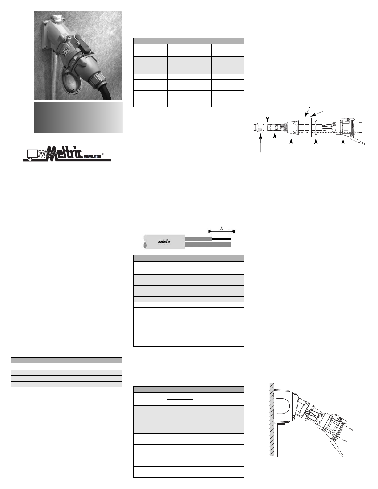
Table 3 - Wire Strip Length – Dimensions A
Receptacle Plug/Inlet
Device Inches mm Inches mm
DSN20 Phase 1/2 13 5/8 16
DSN30 Phase 7/16 10 3/4 19
Auxil. 1/2 12 3/4 19
DSN60 Phase 9/16 14 7/8 22
Auxil. 1/2 13 5/8 16
DS20 Phase 7/16 10 3/4 19
Auxil. 1/2 12 3/4 19
DS30 Phase 9/16 14 7/8 22
Auxil. 1/2 13 5/8 16
DS60 Phase 15/16 24 15/16 24
DS100C Phase 15/16 24 15/16 24
DS100 Phase 1 3/16 30 1 3/16 30
DS200 Phase 1 3/16 30 1 3/16 30
4. Wiring terminals are spring assisted to prevent
loosening due to stand settlement, vibration and
thermal cycling. They should not be over-tightened.
Appropriate tools and tightening torques are indicated in Table 4.
Table 4 - Terminal Screw Tightening Torques
Torque Required Screwdriver
Device/Contact in-lbs N-m or Allen Wrench
DSN20 Phase 7 0.8 3 mm or 1/8” precision tip
DSN30 Phase 13 1.5 4 mm or 3/16” precision tip
Auxil. 13 1.5 4 mm or 3/16” precision tip
DSN60 Phase 16 1.8 5 mm or 3/16” precision tip
Auxil. 7 .8 3 mm or 1/8” precision tip
DS20 Phase 13 1.5 4 mm or 3/16” precision tip
Auxil. 13 1.5 4 mm or 3/16” precision tip
DS30 Phase 16 1.8 5 mm or 3/16” precision tip
Auxil. 7 0.8 3 mm or 1/8” precision tip
DS60 Phase 35 4.0 4 mm hex head
DS100C Phase 35 4.0 4 mm hex head
DS100 Phase 80 9.0 4 mm hex head
DS200 Phase 130 15.0 5 mm hex head
. The DS9 and DS2 are rated as general purpose
5
switches, but are not horsepower rated. If these
evices are installed in motor power supply
d
pplications, warning labels may be required to
a
advise users not to disconnect the device under
oad. Labels are provided in the package, but
l
hould only be used when required.
s
ssembly for In-Line Connections
A
hen Decontactors are used as in-line connectors,
W
inger drawplates (or a drawbar mechanism for the
f
DS9 & DS2) should be installed on both the recepta-
le and plug in order for the user to more easily
c
provide the leverage required to connect the device.
inger Drawplate Gasket
Bushing
Strain
Relief
Compression
Nut
djust the bushing diameter to fit the cable by remov-
A
H
andle
F
olor-Coded
C
asket
G
inger Drawplate
F
eceptacle
R
or Inlet)
(
ing inner sections of it as required. Insert the bushing
into the strain relief, then insert the assembly into the
handle and loosely install the compression nut.
Insert the cable through the handle, the thin black
drawplate gasket and finger drawplate (if applicable)
and the color coded gasket. Strip the cable sheath to
provide a workable wire length, being mindful that the
sheath must extend into the handle to achieve a
secure cord grip. Then strip the individual wires to
the lengths indicated in Table 3 and twist the strands
of each conductor together.
Back out the terminal screws on the receptacle (or
inlet) far enough (but not completely) to allow the
conductors to pass, insert the conductors fully into
their respective terminals and tighten the terminal
screws with the appropriate tool to the torque indicated
in Table 4.
Verify that the cable sheath extends beyond the strain
relief and into the handle. Assemble the receptacle
(or inlet), the color coded gasket, the finger drawplate, and the thin black drawplate gasket to the handle with the four self-tapping screws provided. Adjust
the cable location so that it will not be under tension
inside the handle and tighten the compression nut to
secure the cable.
Assembly for Mounted Receptacles (or Inlets)
In applications where DS or DSN receptacles (or
inlets) are mounted to wall boxes, panels or other
equipment, optimal operation is achieved when the
device is installed with the latch at the top.
nsert the cable or wires through the wall box and cut
I
to allow adequate length, strip the cable sheath as
esired, strip the individual wires to the lengths indi-
d
ated in Table 3, and twist the strands of each con-
c
ductor together. Back out the terminal screws on the
eceptacle (or inlet) far enough (but not completely)
r
o allow the conductors to pass, insert the conductors
t
ully into their respective terminals and hand tighten
f
he terminal screws to the torque indicated in Table 4.
t
ssemble the receptacle (or inlet) and the color-
A
oded gasket to the box with the appropriate hardware.
c
Assemble the mating plug (or receptacle) to the cord
nd as indicated in the assembly instructions above
e
for in-line connections, except there will be no finger
rawplate or associated black gasket.
d
Hole Pattern for Custom Mounting
In applications where custom mounting to a panel or
ox is being performed, the clearance and mounting
b
oles should be drilled as indicated in the following
h
diagram and Table 5.
B
C
able 5 - Custom Mounting Dimensions
T
Model Inches mm Inches mm Inches mm
DSN20
-Recept 2.00 51 1.65 42 .19 5
DSN30 2.25 57 1.89 48 .19 5
DSN60 2.50 64 2.17 55 .19 5
DS20 2.25 57 1.89 48 .19 5
DS30 2.50 64 2.17 55 .19 5
DS60&DS100C 3.25 83 2.59 66 .22 5.5
DS100 4.00 102 3.20 81 .22 5.5
DS200 4.50 114 3.86 98 .28 7
A
‘A’ ‘B’ C
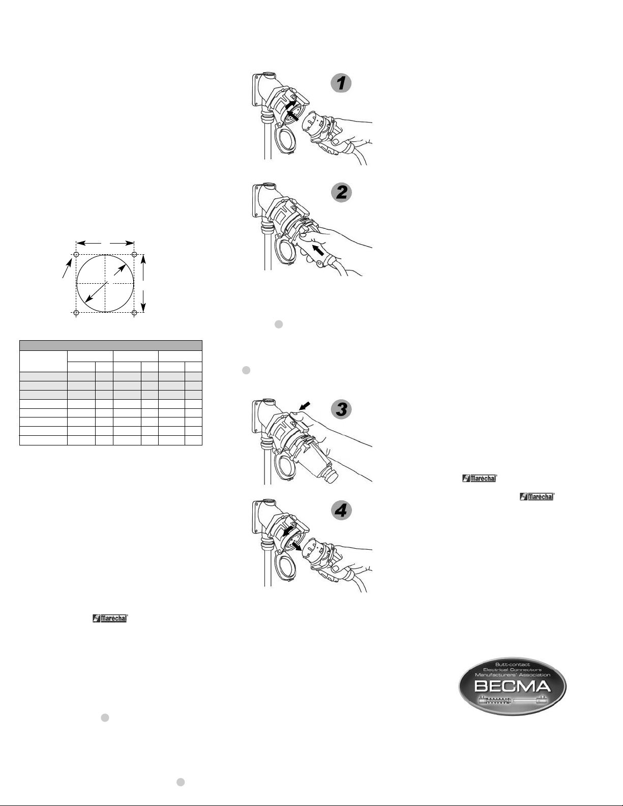
B
t becomes securely latched in place. The electrical
i
connection is now made. On in-line connectors,
queeze the drawplates on both sides of the device
s
ogether until the plug latches in place.
t
isconnection
D
To break the connection, simply depress the pawl as
shown in figure 3 . This will break the circuit and
eject the plug straight out to the rest, or off, position.
The plug contacts are de-energized at this point. To
remove the plug, rotate it counter-clockwise (about
30°) until it releases from the receptacle as shown in
figure 4 . Close and latch the lid on the receptacle.
OTE: Attaching the receptacle locking device with
N
the receptacle lid open will not prevent the insertion
f a plug. Lockout of the receptacle is only accom-
o
lished when the lid is locked closed.
p
MAINTENANCE
eltric products require little on-going maintenance.
M
owever, it is a good practice to periodically perform
H
he following general inspections:
t
Check the mounting screws for tightness.
•
• Verify that the weight of the cable is supported
y the strain relief mechanism and not by the
b
erminal connections.
t
Check the IP gaskets for wear and resiliency.
•
Replace as required.
Verify the electrical continuity of the ground circuit.
•
• Check the contact surfaces for cleanliness and
itting.
p
Deposits of dust or similar foreign materials can be
ubbed off the contacts with a clean cloth. Sprays
r
should not be used, as they tend to collect dirt. If
ny significant pitting of the contacts or other serious
a
amage is observed, the device should be replaced.
d
eceptacle contacts may be inspected by a qualified
R
lectrician. This should only be done with the power
e
ff. It is accomplished by depressing the numbered
o
ring around the circumference of the interior on two
pposite points. This will allow the shutter to be
o
manually turned clockwise as required to permit
access to the contacts. Once the inspection is complete, the shutter must be rotated counter-clockwise
until it is locked in the closed position.
MANUFACTURER’S RESPONSIBILITY
Meltric’s responsibility is strictly limited to the repair
or replacement of any product that does not conform
to the warranty specified in the purchase contract.
Meltric shall not be liable for any penalties or consequential damages associated with the loss of production, work, profit or any financial loss incurred by the
customer.
In order to maintain the NEMA 4X or IP 66 & 67 protection provided by DSN models in custom installations, watertight seals should be used under the
heads of the four mounting bolts and they must be
retained by a lock washer and nut on the inside of
the box or panel. Alternatively, four blind holes may
be drilled and threaded to accommodate the mounting screws, provided that the hole depth is sufficient
to achieve adequate gasket compression.
OPERATION
To ensure safe and reliable operation Meltric plugs
and receptacles must be used in accordance with
their assigned ratings. They can only be used in
conjunction with mating receptacles or plugs manufactured by Meltric or another licensed producer of
products bearing the
TM
Quality Label.
Meltric plugs & receptacles are designed with different keying arrangements, so that only plugs and
receptacles with compatible contact configurations
and electrical ratings will mate with each other.
Connection
To connect a plug and receptacle, first depress the
pawl to open the lid on the receptacle, then orient the
plug as shown in figure 1 so that the red dot on the
outside of the casing lines up with the red dot just to
the left of the latch on the receptacle casing. Push
the plug partially into the receptacle until it hits a
stop, then rotate the plug in the clockwise direction
until it hits another stop after about 30° of rotation.
At this point, the circuit is still open. Push the plug
straight into the receptacle as shown in figure 2 until
Achieving Rated Watertightness
Rated ingress protection applies to the device when
the plug and receptacle are mated and latched
together. It also applies to the receptacle when the
lid is latched closed.
Lockout Provisions
All DS and DSN plugs are provided with lockout provisions. To lockout the plug, insert a locking device
through the hole provided in the casing. This will
prevent the plug from being inserted into a receptacle.
DS and DSN receptacles may be purchased with
optional lockout provisions. To lockout the receptacle,
close and latch the lid and then attach the locking
device through the hole provided in the pawl. This
will prevent the lid from being opened for the insertion of a plug.
Meltric Corporation shall not be held liable when its
products are used in conjunction with products not
bearing the
Meltric products in conjunction with mating devices
that are not marked with the
TM
Quality Label. The use of
M
T
Quality
Label shall void all warranties on the product.
Meltric Corporation is an ISO 9001 certified company.
Its products are designed, manufactured and rated in
accordance with applicable UL, CSA and IEC standards. Meltric is also a member of BECMA, the international Butt-contact Electrical Connectors
Manufacturers’ Association. Like all members,
Meltric additionally designs and manufactures its
products in accordance with BECMA standards
established to ensure intermatablility with similarly
rated products manufactured by other members.
www.becma.ch
INSDS/DSN 072408 E
 Loading...