

DR, DSR,
DN7 & DS7
OPERATING INSTRUCTIONS
Meltric Corporation
4640 Ironwood Drive
Franklin, WI 53132
(800)433-7642
www.meltric.com
GENERAL
Meltric’s DR, DSR, DN7, and DS7 series industrial
plugs and receptacles are designed to ensure user
safety and provide reliable connections. Please follow the instructions below to ensure the proper installation and use of the product.
RATINGS
These products are manufactured and rated in compliance with applicable UL and CSA standards. The
products ratings are indicated on the device labels.
INSTALLATION
These products should be installed by qualified electricians in accordance with all applicable local and
national electrical codes. Before starting, verify that
the power is of
ate for the application, and that the conductors meet
code requirements and are within the capacities of
the terminals noted in
T
Device
DR 30A 14 8 8
DR 50A 12 4 12
DR 100A 6 2 14
DR 150A 4 2/0 14
DR 225A 4 4/0 14
DR 250A 4 4/0 14
DSR 50A 12 4 12
DSR 100A 6 2 14
DSR 150A 4 2/0 14
DN7 50A 14 6 n/a
DN7 90A 8 2 n/a
DN7 150A 4 2/0 10
DS7/DR7 14 6 10
1
Capacity is based on THHN wire sizes.
2
Auxiliary contacts are optional and may not be on all products.
General Notes & Precautions
1. Self-tapping screws are provided for use with
f, that the product ratings are appropri
able 1.
T
erminal Capacity
able 1 - W
iring T
Main Contacts Aux. Contacts
Minimum
Maximum Maximum
Issued: 06/06/2006Rev. A
1
WG)
A
(in
some polymeric accessories. High torque may
be required to drive them in. Once they are
seated, care should be taken in order to avoid
over-tightening them against the plastic material.
2. Various handles and cord grip options may be used.
These instructions are based on handles provided
with integral multi-layer bushing cord grips.
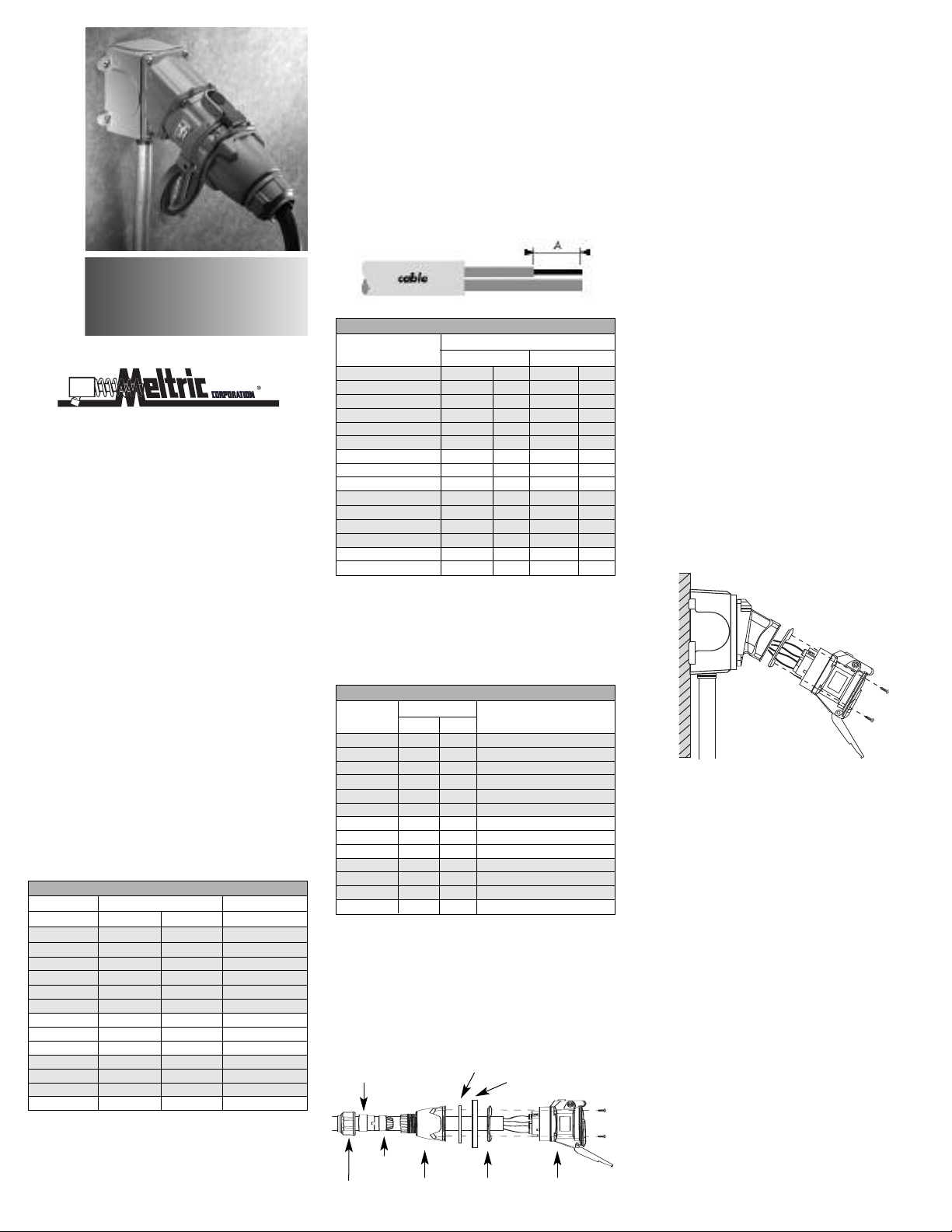
3. Wire strip lengths are indicated in Table 2. Strip
lengths for cable sheathing will depend on the
specific application. When used with handles, the
cable sheathing should extend into the handle to
ensure secure cord gripping.
Table 2 - Wire Strip Lengths – Dimensions A
Receptacle Plug/Inlet
Device Inches mm Inches mm
R 30A 1/2 12 3/4 19
D
R 50A 9/16 14 7/8 22
D
R 100A 15/16 24 15/16 24
D
DR 150A 1 3/16 30 1 3/16 30
DR 225A 1 3/16 30 1 3/16 30
DR 250A
DSR 50A
SR 100A 15/16 24 1
D
SR 150A 1 3/16 3
D
N7 50A 3/4 2
D
DN7 90A 1 2
DN7 150A p
DN7 150A ground 5/8 17 5/8 17
DS7/DR7 phase 1 1/16 27 1 1/16 27
DS7/DR7 auxiliary 5/8 15 5/8 15
hase 1 2
1 3/16 30 1 3/16 30
9/16 14 7/8 22
0 1 3/16 3
0 3/4 2
5 1 2
6 1 26
4. Wiring terminals are spring assisted to prevent
loosening due to stand settlement, vibration and
thermal cycling. They should not be over-tightened.
Appropriate tools and tightening torques are
indicated in Table 3.
Table 3 - Terminal Screw Tightening Torques
Torque Required Screwdriver
Device in-lbs N-m or Allen Wrench
DR 30A 13 1.5 4 mm or 3/16” precision tip
DR 50A 16
DR 100A 35 4.0 1/4” precision tip
DR 150A 80 9.0 4 mm hex head
DR 225A 130 15.0 5 mm hex head
-
DR 250A 130 15.0 5 mm hex head
DSR 50A 16 1.8 5 mm or 3/16” precision tip
DSR 100A 35 4.0 1/4” precision tip
DSR 150A 80 9.0 4 mm hex head
DN7 50A 13 1.5 4 mm or 3/16” precision tip
DN7 90A 30 3.5 7 mm or 1/4” precision tip
DN7 150A 80 9.0 4 mm hex head
2
DS7/DR7 16 1.8 3.5 mm or 1/8” precision tip
1.8 5 mm or 3/16” precision tip
Assembly for In-Line Connections
When these products are used as in-line connectors,
finger drawplates (or a drawbar mechanism) should
be installed on both the receptacle and plug in order
for the user to more easily provide the leverage
required to connect the device.
Bushing
Compression
Nut
Strain
Relief
Handle
Finger Drawplate Gasket
Finger Drawplate
Color-Coded
Gasket
5/16 24
Receptacle
(or Inlet)
Adjust the bushing diameter to fit the cable by removing inner sections of it as required. Insert the bushing into the strain relief, then insert the assembly into
the handle and loosely install the compression nut.
I
nsert the cable through the handle, the thin black
drawplate gasket and finger drawplate (if applicable)
and the color coded gasket. Strip the cable sheath to
provide a workable wire length, being mindful that the
sheath must extend into the handle to achieve a
secure cord grip. Then strip the individual wires to
the lengths indicated in Table 2 and twist the strands
of each conductor together.
Back out the terminal screws on the receptacle (or
inlet) far enough (but not completely) to allow the
conductors to pass, insert the conductors fully into
t
heir respective terminals and tighten the terminal
screws with the appropriate tool to the torque
indicated in Table 3.
Verify that the cable sheath extends beyond the
s
train relief and into the handle. Assemble the receptacle (or inlet), the color coded gasket, the finger
drawplate, and the thin black drawplate gasket to the
handle with the four self-tapping screws provided.
Adjust the cable location so that it will not be under
t
ension inside the handle and tighten the compres-
sion nut to secure the cable.
Assembly for Mounted Receptacles (or Inlets)
In applications where the receptacles (or inlets) are
mounted to wall boxes, panels or other equipment,
0
optimal operation is achieved when the device is
0
installed with the latch at the top.
5
Insert the cable or wires through the wall box and cut
to allow adequate length, strip the cable sheath as
desired, strip the individual wires to the lengths indicated in Table 2, and twist the strands of each conductor together. Back out the terminal screws on the
receptacle (or inlet) far enough (but not completely)
to allow the conductors to pass, insert the conductors
fully into their respective terminals and hand tighten
the terminal screws to the torque indicated in Table 3.
Assemble the receptacle (or inlet) and the colorcoded gasket to the box with the appropriate hardware. Assemble the mating plug (or receptacle) to
the cord end as indicated in the assembly instructions above for in-line connections, except there will
be no finger drawplate or associated black gasket.
Hole Pattern for Custom Mounting
In applications where custom mounting to a panel or
box is desired, the clearance and mounting holes
should be drilled as indicated in the following diagram
and Table 4.

B
C
Tab le 4 - Cus tom Mo unt ing D ime nsi ons
‘A’ ‘B’ ‘C’
Model Inches mm Inches mm Inches mm
DR 30A 2.25 57 1.89 48 .19 5
DR 50A 2.50 64 2.17 55 .19 5
DR 100A 3.25 83 2.59 66 .22 5.5
DR 150A 4.00 102 3.20 81 .22 5.5
DR 225A 4.50 114 3.86 98 .28 7
DR 250A 4.50 114 3.86 98 .28 7
DSR 50A 2.50 64 2.17 55 .19 5
DSR 100A 3.25 83 2.59 66 .22 5.5
DSR 150A 4.00 102 3.20 81 .22 5.5
DN7 50A 3.25 83 2.59 66 .22 5.5
DN7 90A 4.00 102 3.20 81 .22 5.5
DN7 150A 4.50 114 3.86 98 .28 7
DS7/DR7 3.25 83 2.59 66 .22 5.5
A
B
OPERATION
To e n su r e s a fe an d re l ia b le op e ra t io n Me l tr i c p lu g s
and receptacles must be used in accordance with
their assigned ratings. They can only be used in
conjunction with mating receptacles or plugs manufactured by Meltric or another licensed producer of
products bearing the
TM
Quality Label.
Meltric plugs & receptacles are designed with different keying arrangements, so that only plugs and
receptacles with compatible contact configurations
and electrical ratings will mate with each other.
Connection
To c o nn e ct a p l ug a nd re c ep t ac l e, f ir s t d ep r es s th e
pawl to open the lid on the receptacle, then orient the
plug as shown in figure 1 so that the red dot on the
outside of the casing lines up with the red dot just to
the left of the latch on the receptacle casing. Push
the plug partially into the receptacle until it hits a
stop, then rotate the plug in the clockwise direction
until it hits another stop after about 30° of rotation. At
this point, the circuit is still open. Push the plug
straight into the receptacle as shown in figure 2 until
it becomes securely latched in place. The electrical
connection is now made. On in-line connectors,
squeeze the drawplates on both sides of the device
together until the plug latches in place.
Disconnection
To b r ea k th e c o nn e ct i on , si m pl y d e pr e ss t he pa w l a s
shown in figure 3 . This will break the circuit and
eject the plug straight out to the rest, or off, position.
The plug contacts are de-energized at this point. T
o
remove the plug, rotate it counter-clockwise (about
30°) until it releases from the receptacle as shown in
figure 4 . Close and latch the lid on the receptacle.
Achieving Rated Watertightness
Rated ingress protection applies to the device when
the plug and receptacle are mated and latched
together. It also applies to the receptacle when the
lid is latched closed.
Lockout Provisions
Some Meltric plugs are provided with lockout provisions. To lockout the plug, insert a locking device
through the hole provided in the casing. This will
prevent the plug from being inserted into a receptacle.
Some receptacles may be purchased with optional
lockout provisions. To lockout the receptacle, close
and latch the lid and then attach the locking device
through the hole provided in the pawl. This will prevent the lid from being opened for the insertion of a
plug.
NOTE: Attaching the receptacle locking device with
the receptacle lid open will not prevent the insertion
of a plug. Lockout of the receptacle is only accomplished when the lid is locked closed.
Deposits of dust or similar foreign materials can be
rubbed off the contacts with a clean cloth. Sprays
should not be used, as they tend to collect dirt. If
any significant pitting of the contacts or other serious
damage is observed, the device should be replaced.
Receptacle contacts may be inspected by a qualified
electrician. This should only be done with the power
off. It is accomplished by depressing the numbered
ring around the circumference of the interior on two
opposite points. This will allow the shutter to be
manually turned clockwise as required to permit
access to the contacts. Once the inspection is complete, the shutter must be rotated counter-clockwise
until it is locked in the closed position.
MANUF
ACTURER’S RESPONSIBILITY
Meltric’
s responsibility is strictly limited to the repair
or replacement of any product that does not conform
to the warranty specified in the purchase contract.
Meltric shall not be liable for any penalties or consequential damages associated with the loss of production, work, profit or any financial loss incurred by the
customer.
Meltric Corporation shall not be held liable when its
products are used in conjunction with products not
bearing the
Meltric products in conjunction with mating devices
that are not marked with the
TM
Quality Label. The use of
TM
Quality
Label shall void all warranties on the product.
Meltric Corporation is an ISO 9001 certified
company. Its products are designed, manufactured
and rated in accordance with applicable UL, CSA and
IEC standards. Meltric is a also member of BECMA,
the international Butt-contact Electrical Connectors
Manufacturers’ Association. Like all members,
Meltric additionally designs and manufactures its
products in accordance with BECMA standards
established to ensure intermatablility with similarly
rated products manufactured by other members.
MAINTENANCE
Meltric products require little on-going maintenance.
However, it is a good practice to periodically perform
the following general inspections:
• Check the mounting screws for tightness.
• Verify that the weight of the cable is supported
by the strain relief mechanism and not by the
terminal connections.
• Check the IP gaskets for wear and resiliency.
Replace as required.
• Verify the electrical continuity of the ground circuit.
• Check the contact surfaces for cleanliness and
pitting.
CUSTINFO/DR-DSR-DN7-DS7
Coutesy of Gross Automation 1724 South Johnson Road New Berlin, WI PH: 262-446-0000 FAX: 262-446-0300 www.meltricsales.com
 Loading...