

Meltric CS1000 User Manual
OPERATING INSTRUCTIONS
WARNING
CS1000
NSCS1000 C
I
eltric Corporation / 4640 Ironwood Drive Franklin, WI 53132
M
Tel. : 800 433 7642 / Fax : 414 817 6161 / e-mail : mail@meltric.com
manufacturer of products using M arechal technology
A
he tightening torque must not be transmitted
T
to the insulated casing. To avoid transmitting
orque to the device when securing the lugs, hold the
t
erminal in place with a 24 mm wrench.
t
hile tightening the ferrule of the screw, maintain the
W
ear of the CS contact with a 21 mm wrench. Apply a
r
orque of 30 ft-lb (40 N-m).
t
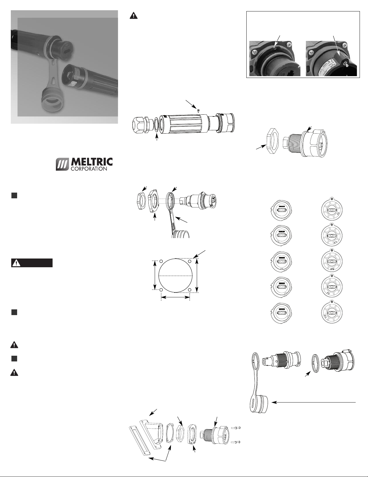
Assembly of the handle
crew handle onto the product and tighten the cable
S
gland with an appropriate tool. Block the rotation of
he handle with the supplied screw. Assemble as
t
shown below.
crew to block rotation
S
Watertightness gasket
Assembly with adapter plate
hen mounting on a wall or panel, position the inlet or
W
eceptacle so that the locking pin or latch is at the top.
r
Locking latch Locking pin
ssembly on a panel board
A
irect assembly
D
ssemble the product on the panel board and tighten
A
the M40 nut supplied, with an appropriate tool. The
watertightness is achieved by the color-coded ring.
Color-coded ring
M40 nut
meltric.com
GENERAL
CS1000 single pole plugs and connectors are
designed with safety and durability in mind. A finger
guard on the receptacle provides IP2X protection
from live parts. A locking pin prevents unwanted
disconnection. Each of the phases as well as the
neutral and ground are color coded and keyed to
prevent improper connection. Please follow the
instructions below to ensure the proper installation
and use of the product.
There are inherent dangers
associated with electrical
products. Failure to follow safety precautions can
result in serious injury or death. These instructions
must be followed to ensure the safe and proper
installation, operation and maintenance of the Meltric
devices. Before installation, disconnect all sources
of power to the circuit to eliminate the risk of
electrical shock.
RATINGS
The CS1000 series is for use in Non-Load Break
applications up to 400A at 600VAC (in North
America) or 1000VAC (in Europe – CE rated).
The CS1000 devices are NOT designed or
listed for current interruption.
INSTALLATION
These products should be installed by qualified
personnel in accordance with all applicable
local and national electrical codes.
Before starting, verify that the power is off, that the
product ratings are appropriate for the application,
and that the conductors meet code requirements.
NOTICE: For correct operation, the power cable
must not exert significant force on the product.
Wiring of the main conductor
Strip the conductor by approximately 1-1/8” depending on
the lug used. Crimp the threaded lug or the ferrule with
the appropriate die. Hexagonal crimping is recommended.
Tighten the threaded lug with a 21 mm wrench or
tighten the ferrule with a screw and washer with a
19 mm socket.
Assemble the adaptor plate on the product and
tighten the M40 nut with an appropriate tool.
lign tabs and assemble as shown below.
A
M4
0
nut
Ada
pt
p
l
a
t
Hole pattern for adapter plate
Ca
p wi
t
h Col
or
-
c
ode
d
r
i
ng
e
r
e
1.89”
Ca
p (
pa
r
t
i
a
l
v
i
e
w)
.19Ø mount
holes
2.25”1.89”
NOTICE: In order to maintain IP66 / 67 protection in
custom installations, watertight seals must be used
under the heads of the four mounting fasteners and
they must be retained by a lock washer and nut on
the inside of the box or panel. Alternatively, four
blind holes can be drilled and threaded to
accommodate #8-32 x 5/8” mounting screws. The
hole depth must be sufficient to achieve adequate
gasket compression.
Assembly on an inclined sleeve
(with adapter plate)
Assemble the adapter plate on the inclined sleeve.
Do not forget the gasket between the adaptor plate
and the inclined sleeve, and between the inclined
sleeve and the panel. Assemble as shown below.
Inclined sleeve
M40 nut
Watertightness gaskets
Color-coded ring
Adapter plate
Color coded ring and color-coded ring for the lid
In order to achieve watertightness, do not forget the
olor-coded ring at the rear of the inlet or receptacle
c
and the panel.
Receptacle
(Female)
Earth
Phase1
Phase2
Negative
Phase3
Negative
Neutral
Plugs
(Male)
The
color-coded rings of receptacles and connectors
include a cap. The color-coded rings of plugs and
inlets do not include a cap.
Color-coded ring on plug side
Cap with color-coded ring on receptacle side
Rated current and voltage markings
It is essential to indicate the current and voltage of
the main circuit on the supplied stickers. Apply the
stickers on or adjacent to the product so they can
easily be seen.
PERATION
WARNING
O
o ensure safe and reliable operation, Meltric
T
lugs and receptacles must be used in
p
accordance with their assigned ratings.
hey can only be used in conjunction with mating
T
eceptacles or plugs manufactured by Meltric or
r
nother licensed producer of products bearing
a
the
onnection
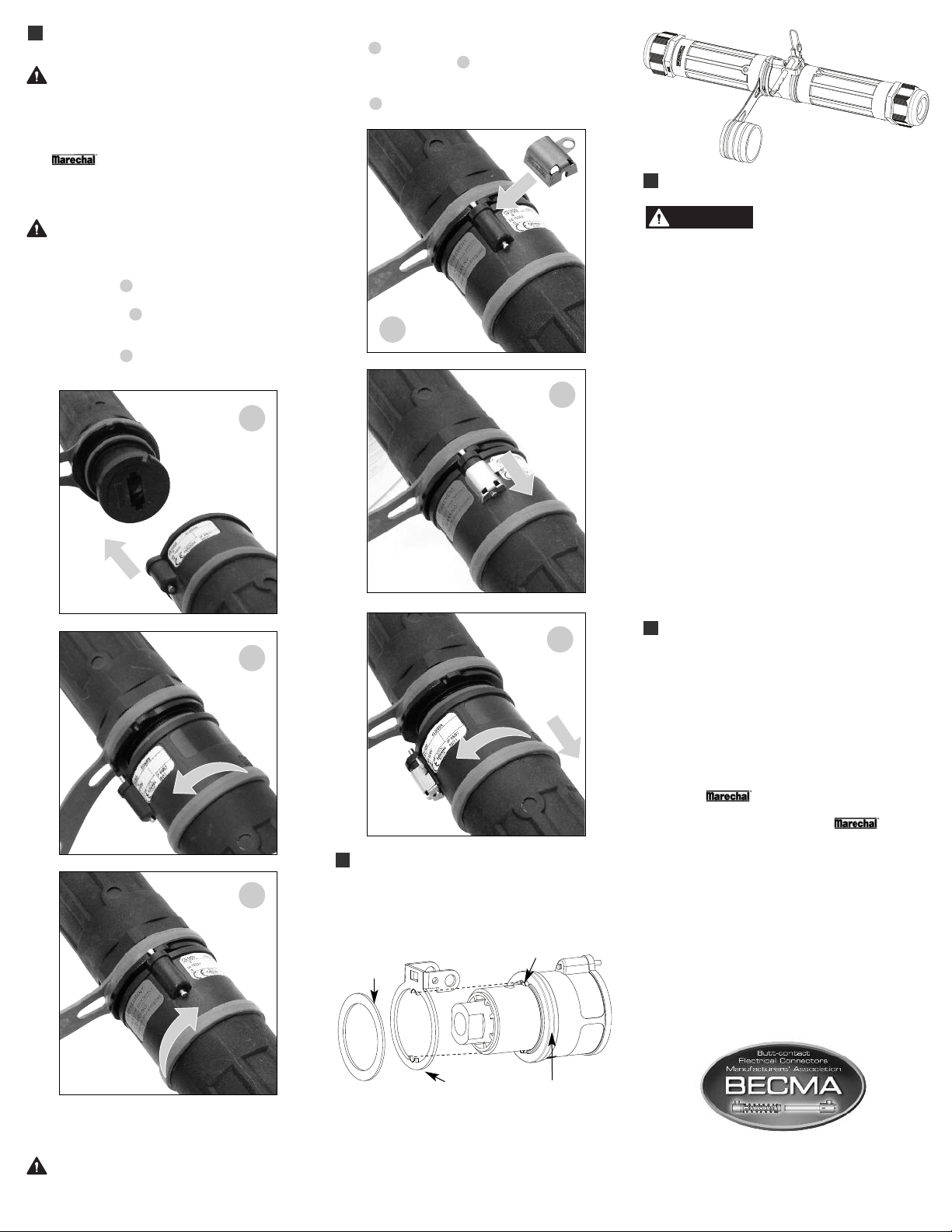
C
Orient the plug so the contact will fit into the
eceptacle figure 1 . Push the plug partially into the
r
receptacle and rotate the plug counterclockwise until
t hits a stop figure 2 . Then insert plug fully into
i
eceptacle and rotate clockwise about one quarter
r
turn until the locking pin engages into the slot on the
eceptacle figure 3 .
r
M
T
technology trademark.
irst check to see that the power source is
F
de-energized. DO NOT ENGAGE ON AN
NERGIZED CIRCUIT.
E
1
nsert unlocking key onto locking pin as shown in
I
figure 4 . Disengage locking pin by sliding unlocking
ey as shown in figure 5 . When locking pin is
k
eleased, hold unlocking key in position and twist
r
plug counterclockwise about 30° as shown in
igure 6 . After turning, withdraw plug.
f
nsert
I
unlock
4
tool
5
etract
R
ocking
l
pin
MAINTENANCE
Before inspecting, repairing, or
isconnect electrical power to the receptacle to
d
eliminate the risk of electrical shock.
eltric products require little on-going maintenance.
M
However, it is a good practice to periodically perform
he following general inspections:
t
Check the mounting screws for tightness.
•
Verify that the weight of the cable is supported
•
y the strain relief mechanism and not by the
b
terminal connections.
Check the IP gaskets for wear and resiliency.
•
Replace as required.
• Verify the electrical continuity of the ground circuit.
• Check the contact surfaces for cleanliness and
pitting.
maintaining Meltric products,
Insert
2
Twist then
insert
3
Twist until
pin locks
PADLOCKING OPTION
Assembly
Place the locking ring as shown:
Watertightness
gasket
6
Twist &
Remove
Lug
Deposits of dust or similar foreign materials can be
rubbed off the contacts with a clean cloth. Sprays
should not be used, as they tend to collect dirt. If
any significant pitting of the contacts or other serious
damage is observed, the device should be replaced.
Receptacle contacts may be inspected by a qualified
electrician. This should only be done with the power off.
MANUFACTURER’S RESPONSIBILITY
Meltric’s responsibility is strictly limited to the repair
or replacement of any product that does not conform
to the warranty specified in the purchase contract.
Meltric shall not be liable for any penalties or
consequential damages associated with the loss of
production, work, profit or any financial loss incurred
by the customer.
Meltric Corporation shall not be held liable when its
products are used in conjunction with products not
bearing the
use of Meltric products in conjunction with mating
devices that are not marked with the
technology trademark shall void all warranties on
the product.
Meltric Corporation is an ISO 9001 certified
company. Its products are designed, manufactured
and rated in accordance with applicable UL, CSA and
IEC standards. Meltric is a also member of BECMA,
the international Butt-contact Electrical Connectors
Manufacturers’ Association. Like all members,
Meltric additionally designs and manufactures its
products in accordance with BECMA standards
established to ensure intermatablility with similarly
rated products manufactured by other members.
TM
technology trademark. The
M
T
Disconnection
First check to see that the power source is
de-energized. DO NOT DISCONNECT ON
AN ENERGIZED CIRCUIT.
Locking ring
Operation
Connect the product equipped with the locking ring,
insert the shaft and padlock it.
Color-coded ring
www.becma.ch
INSCS1000 C
 Loading...