

Page 1

Melten
M2 Nurse Call Module
User Guide
Model NO.: BM-B01
Page 2
Revision History
Version
Date
Revision
0.1
2018.7.1
First Draft
0.2
2018.8.16
Add the FCC warning messages in the “Important Notice” section.
0.3
2018.8.20
Modify the product name and add the product specification table.
0.4
2018.8.21
Add the product model number
Page 3
Important Notice
All Rights Reserved
No part of this publication may be reproduced, transcribed, or transmitted in any form, or by
any means electronic or mechanical, including photocopying and recording, for any purpose
other than the purchaser’s use without written permission of Melten Inc. (Melten).
Trademarks
Melten is a registered trademark.
Warranty and Limited Liabilities Disclaimer
Information in this document is subject to change and does not represent a commitment by
Melten. Changes made to the information in this document will be incorporated in new
editions of the publication. No responsibility is assumed by Melten for the use or reliability of
software or equipment that is not supplied by Melten or its affiliated dealers.
Melten warrants this product free from defects in material or workmanship for a period of 12
months from the ship date, except as noted. The product warranty does not cover damage
caused by misuse, abuse, act of gods, the attachment of any accessory/components not
provided by Melten, alteration to the product, improper installation, lack of proper
maintenance, or any other conditions that are beyond the control of Melten. Melten shall not
be responsible for any type of incidental, consequential, or special damages. All implied
warranties, including but not limited to those warranties of fitness and merchantability, are
limited in the total duration to 12 months from the original ship date. Claims for lost
shipment, damaged shipments, or other problems regarding freight must be made directly
to the responsible carrier. Melten disclaims any and all liability for consequential or incidental
damages. No responsibility is assumed by Melten for the use or reliability of software or
equipment that is not supplied by Melten.
Precaution
Page 4
All peripheral or connected devices such as network switch, server, or software must be
tested and verified by Melten before installations.
BM-A01 supports BT4.0 and WiFi (802.11 b/g/n) interfaces. The configuration can only be
configured by certified Melten engineers and please also contact Melten before using it.
Changing the radio frequency and power is prohibited and may consequently violates the
radiation law in any country.
*Maximum wireless signal rate derived from IEEE Standard 802.11ac and 802.11n specifications. Actual data
throughput will vary. Network conditions and environmental factors, including volume of network traffic,
building materials and construction, and network overhead, lower actual data throughput rate. Environmental
conditions will adversely affect wireless signal range.
⚫ 802.11n/g/b/a Compatible
⚫ BT4.0 Supported
⚫ Operating Temperature: 0°C (32°F)~+40°C (104°F)
⚫ Storage Temperature: 0°C (32°F)~+50°C (122°F)
⚫ Humidity Control: 20% to 80% (non-condensing)
A Statement and Advisory from Melten Inc.
This manual is designed to instruct all personnel responsible for proper installation, use and
care of the Melten Smart Ward IoT System and M2 nurse call module. All users are urged to
carefully read these instructions before operating the system.
The instructions described in this manual are the only officially approved operating methods
by Melten Inc. (Melten) and should be followed except for any statutory obligation. All users
and technicians should become familiar with the warnings, cautions, and instructions
contained herein. Do not operate or service the system until you have become familiar with
this information.
The system must be installed and serviced by competent personnel. Do leave this manual
with the users and technicians after installation. If you are in any doubt, contact your Melten
representative for details.
Federal Communications Commission Interference Statement
Page 5
This equipment has been tested and found to comply with the limits for a Class B digital
device, pursuant to part 15 of the FCC Rules. These limits are designed to provide reasonable
protection against harmful interference in a residential installation. This equipment
generates, uses and can radiate radio frequency energy and, if not installed and used in
accordance with the instructions, may cause harmful interference to radio communications.
However, there is no guarantee that interference will not occur in a particular installation. If
this equipment does cause harmful interference to radio or television reception, which can be
determined by turning the equipment off and on, the user is encouraged to try to correct the
interference by one or more of the following measures:
-Reorient or relocate the receiving antenna.
-Increase the separation between the equipment and receiver.
-Connect the equipment into an outlet on a circuit different from that to which the receiver
is connected.
-Consult the dealer or an experienced radio/ TV technician for help.
Caution:
Any changes or modifications not expressly approved by the grantee of this device could
void the user's authority to operate the equipment.
RF Exposure Warning
This equipment must be installed and operated in accordance with provided instructions and
the antenna(s) used for this transmitter must be installed to provide a separation distance of
at least 20 cm from all persons and must not be co-located or operating in conjunction with
any other antenna or transmitter. End-users and installers must be provided with antenna
installation instructions and transmitter operating conditions for satisfying RF exposure
compliance.
Page 6
Melten Inc.
Customer Service and Sales
Website: http://melten.com
Phone: +886-2-22670607
FAX: +886-2-22674427
E-Mail: [email protected]
Page 7

Table of Contents
1. Introduction ................................................................................................................... 1
2. System Overview ............................................................................................................ 1
3. Before Using ................................................................................................................... 1
4. System Device List .......................................................................................................... 2
5. Smart Ward IoT System Architecture ............................................................................. 3
6. System Device Introduction ........................................................................................... 4
6.1 M2 Nurse Call Module ....................................................................................................................... 4
6.1.1 M2 Front View ..................................................................................................................................................... 4
6.1.2 M2 Front Panel User Interface Functionalities .................................................................................................... 4
6.1.3 M2 Side View ....................................................................................................................................................... 5
6.1.4 M2 Touch Screen User Interface ......................................................................................................................... 5
6.2 Nurse Call Cords ................................................................................................................................ 6
6.2.1 Nurse Call Cords Components ............................................................................................................................. 6
6.2.2 Nurse Call Cords Component Functionalities ...................................................................................................... 6
6.3 Bathroom Call Unit ............................................................................................................................ 7
6.3.1 Bathroom Call Unit Components ......................................................................................................................... 7
6.3.2 Bathroom Call Unit Functionalities ...................................................................................................................... 7
6.4 Nurse Station IP Phone ...................................................................................................................... 8
6.4.1 Nurse Station IP Phone Exterior View .................................................................................................................. 8
6.4.2 Nurse Station IP Phone Functionalities ................................................................................................................ 8
6.5 Double-sided Corridor Display .......................................................................................................... 9
6.5.1 Corridor Display Exterior View ............................................................................................................................. 9
6.5.2 Corridor Display Functionalities ........................................................................................................................... 9
6.6 Dome Light (4 Colors) ...................................................................................................................... 10
6.6.1 Dome Light Exterior View .................................................................................................................................. 10
6.6.2 Dome Light Functionalities ................................................................................................................................ 10
6.7 Patient Call Display (PCD) ................................................................................................................ 11
6.7.1 PCD User Interface ............................................................................................................................................. 11
6.7.2 PCD Functionalities ............................................................................................................................................ 11
6.8 Nurse Station Dashboard ................................................................................................................ 12
6.8.1 Nurse Station Dashboard User Interface ........................................................................................................... 12
Page 8
6.8.2 Nurse Station Dashboard Functionalities .......................................................................................................... 12
6.9 Smart Phone .................................................................................................................................... 13
6.9.1 Smart Phone Exterior View ................................................................................................................................ 13
6.9.2 Smart Phone Functionalities .............................................................................................................................. 13
7. M2 User Interface Introduction .................................................................................... 14
7.1 M2 User Interface ............................................................................................................................ 14
7.2 Switch Flow of the Special Needs and Condition Display ............................................................... 15
8. M2 Nurse Call Module Specifications ........................................................................... 18
Page 9
1
1. Introduction
Melten Smart Ward IoT System is provided to the patient’s family, caregivers or nurses
who respond to the assistance calls from the bedside and need to react quickly. This
document mainly describes the architecture and installation procedures of Smart Ward
IoT System.
2. System Overview
The system is designed to be installed in the ward rooms of the hospitals, providing
real-time communication between the patients and nursing staffs through the
connection with telephone exchanges, wireless telephones and computers. It allows
the medical and nursing personnel to receive and respond to every information
coming from this system at any time. It meets the goals of medical service quality
improvement and fulfill the management needs.
3. Before Using
All peripheral or connected devices such as network switch, server, or software must be
tested and verified by Melten before using.
Page 10
2
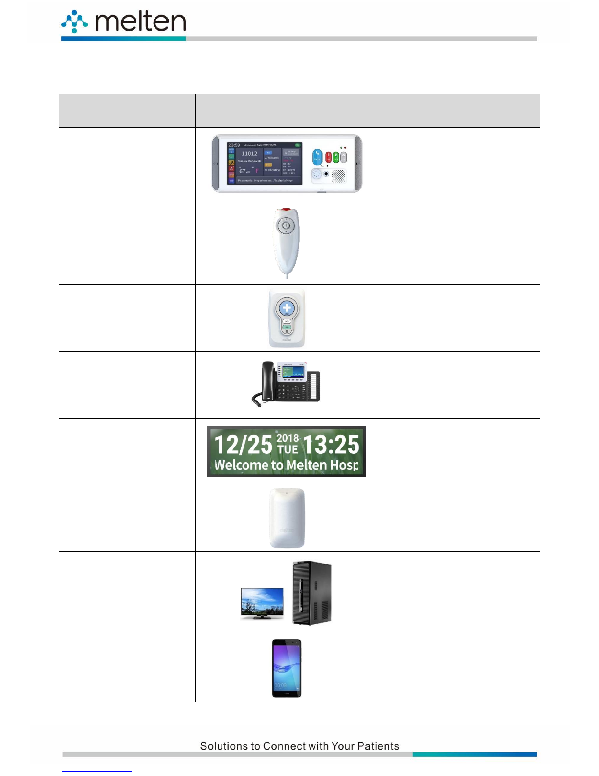
4. System Device List
Device Name
Device Image
Installation Area
M2 Nurse Call Module
Bedside
Nurse Call Cords
Nurse Call Unit
Bathroom Call Unit
Ward Bathroom
IP Telephone Attendant
Console
Nurse Station
Corridor Display
Hospital Corridor
Dome Light
Ward Doorway
22” Display (PCD Display
& Smart Dashboard) +
Computer Host x 2
Nurse Station
Smart Phone
Portable phone carried by
nursing staff
Page 11
3
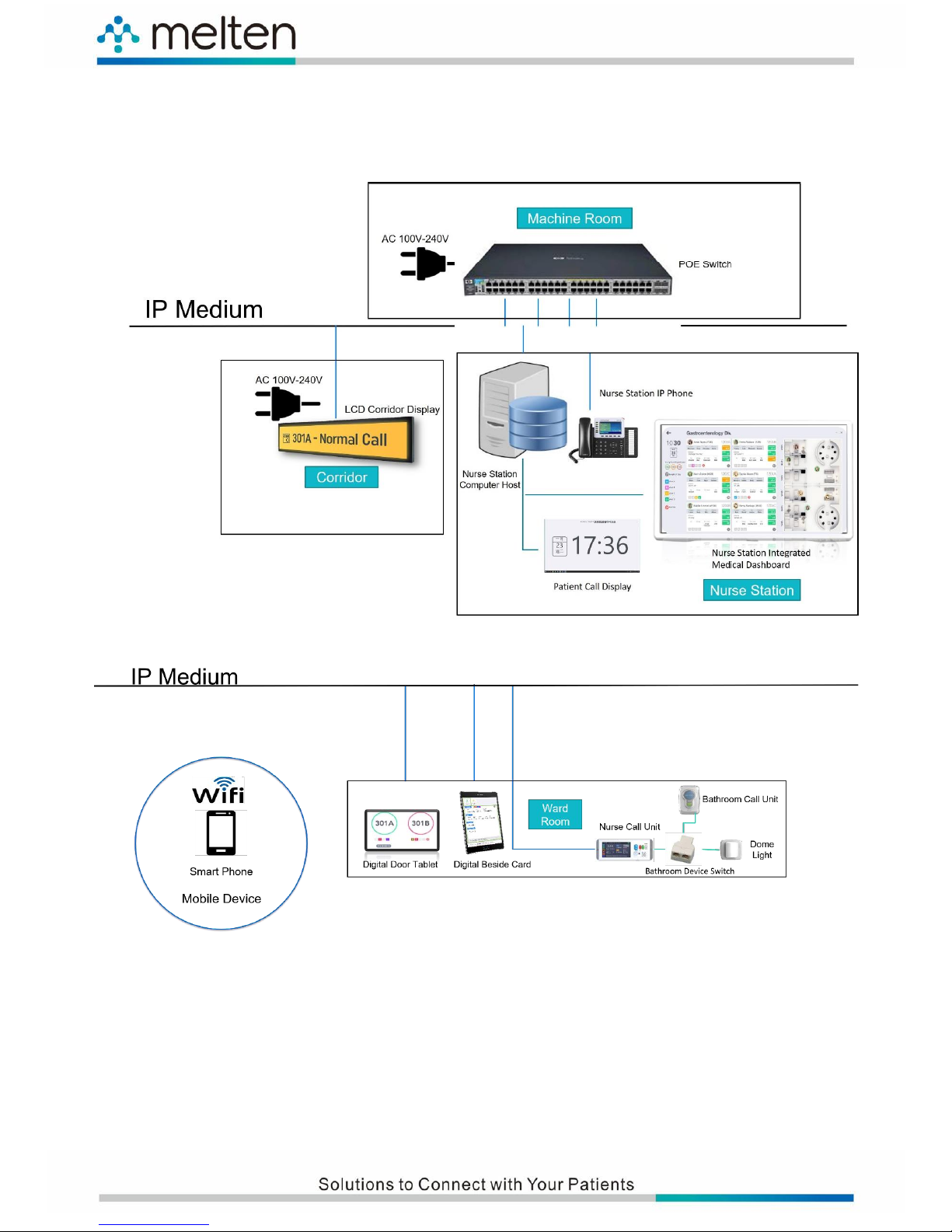
5. Smart Ward IoT System Architecture
Page 12
4
Multi-function Expansion Port
6. System Device Introduction
6.1 M2 Nurse Call Module
6.1.1 M2 Front View
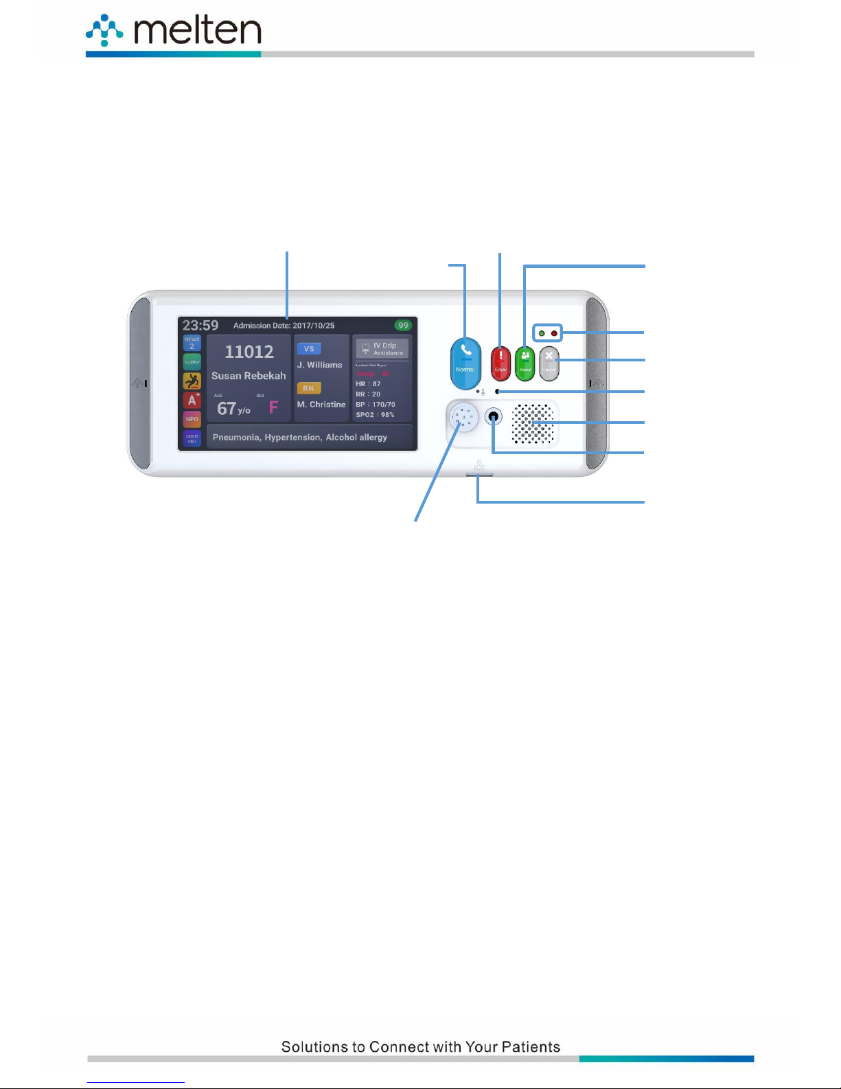
6.1.2 M2 Front Panel User Interface Functionalities
⚫ 7" Touchscreen Display: Displays real-time patient information, medical care notes,
inspection schedules and medical care team members.
⚫ Normal Call Button: Press this button to call the nursing staff when a normal situation
needs to be handled.
⚫ Emergency Call Button: Press this button to call the nursing staff when an emergency
situation needs to be taken care of. When receiving an emergency call, the message will
be simultaneously displayed on the monitors of Nurse Station Host, Corridor Displays,
Smart Phone and Mobile Medical Cart.
⚫ Assist Call Button: To call other groups of nursing staff for assistance, press this button.
⚫ Cancel Button: To cancel a call, press this button.
⚫ Call Event LED Indicator: Distinguishes different event types by displaying different
colors.
⚫ Microphone Hole: Receives the voice signal of the patient call.
⚫ Speaker: Transmits the voice signal sent by nursing staff.
⚫ Headphone Jack: For functional expansion and connectivity with other equipment
⚫ RJ 45/Ethernet Port: Connects with vital sign equipment and uploads data instantly.
7" Touchscreen Display
Normal Call Button
Cancel Button
Emergency Call Button
Assist Call Button
Call Event LED Indicator
Microphone Hole
Speaker
Headphone Jack
RJ45 LAN Port
Page 13
5
Time
Current Date
Admission Date
Inpatient Days
Latest Vital
Sign Data
Special Needs and
Condition Display
(Switchable)
Special Notes
(Text)
Patient Basic Information
Care Team
Special Notes
⚫ Multi-function Expansion Port: Connects with call cords or other medical equipment and
synchronizes with Intelligent Nurse Call System. When connected with the attachable call
cord, it supports Fall Detection function.
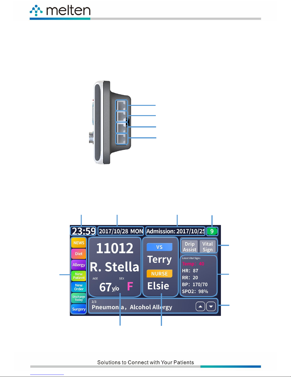
6.1.3 M2 Side View
6.1.4 M2 Touch Screen User Interface
PoE Power Port
LAN Port (Reserved for extension port)
LAN Port (Used for connecting to the
Dome Light and Bathroom Call Unit)
LAN Port (Used for connecting to the monitor)
Page 14
6
Front View
Rear View
LED Indicator
Volume Control
Button
Call Button
Microphone
Hole
6.2 Nurse Call Cords
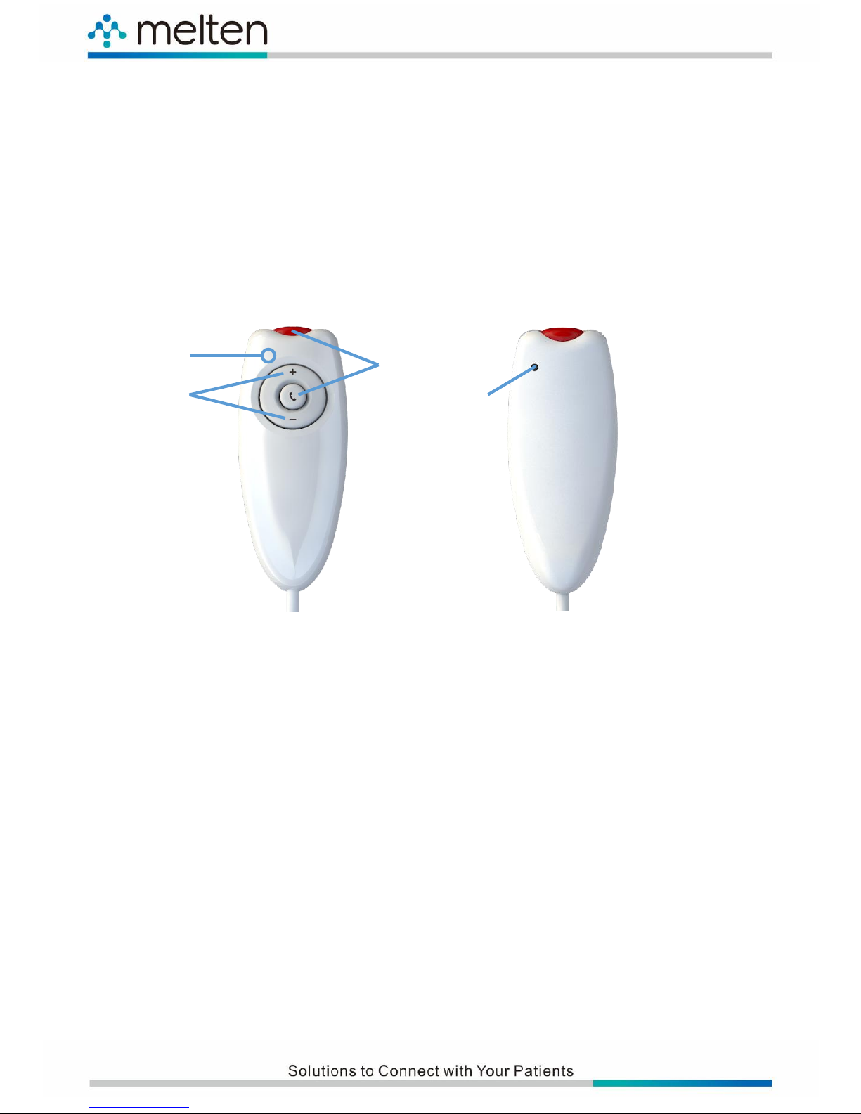
The nurse call cords are designed for the bedridden patients to call the nursing staff in
a quick and easy way.
6.2.1 Nurse Call Cords Components
6.2.2 Nurse Call Cords Component Functionalities
⚫ Call Button: Press this button to call the nursing staff when a normal situation needs to
be handled.
⚫ LED Indicator: When pressing the call button, this LED indicator will illuminate.
⚫ Microphone Hole: Receives the voice signal of the patient call.
⚫ Volume Control Button: Allows the patients to adjust the speaker volume.
Page 15
7
Emergency Call Button
Cancel Button
Assist Call Button
LED Indicator
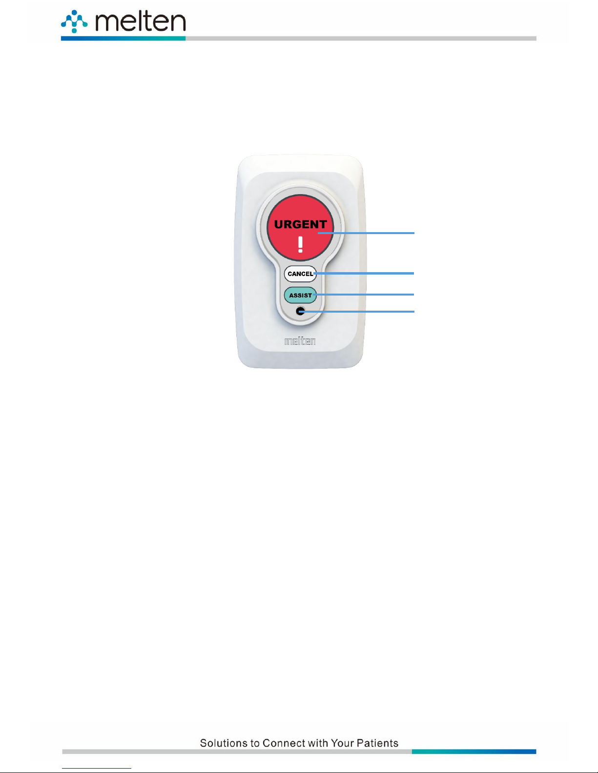
6.3 Bathroom Call Unit
6.3.1 Bathroom Call Unit Components
6.3.2 Bathroom Call Unit Functionalities
⚫ Emergency Call Button: Press this button to call the nursing staff when an emergency
situation needs to be taken care of.
⚫ Cancel Button: To cancel a call, press this button. A bathroom emergency call can only be
cancelled by pressing the “Cancel Button” of bathroom call unit.
⚫ Assist Call Button: To call other groups of nursing staff for assistance, press this button.
⚫ Call Display LED Indicator: When pressing the Call Button, this LED indicator will
illuminate.
Page 16
8
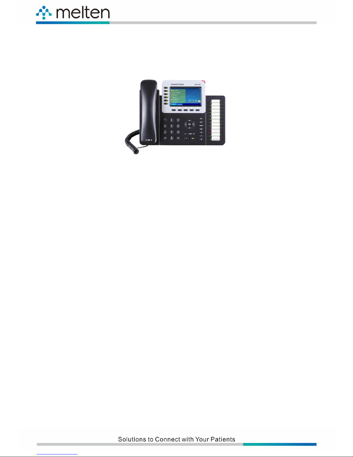
6.4 Nurse Station IP Phone
6.4.1 Nurse Station IP Phone Exterior View
6.4.2 Nurse Station IP Phone Functionalities
⚫ Power and Function Light Indicators
A. Allows a set of 4 characters (including the above) and 10 sets (including the above)
of caller ID automatically displayed in turns. The caller ID and waiting calls will be
displayed actively.
B. With volume control function
⚫ Answering the calls from every ward bed and providing intercommunication capability
(Two-way conversation between nurse station and ward bed)
A. The call signals are categorized into the following 3 types: Normal Call, Emergency
Call and Assist Call. These calls will be automatically distinguished by the calling
sequence.
B. It supports smart mobile phone conversation method. When the patient calls and
the nurses are away from the nurse station or they are making their rounds, the
portable smart phone will simultaneously ring and vibrate, allowing the nurses to
answer the patient’s calls. In addition, the nurses are able to call and notify other
nursing staff through the broadcasting function, or directly call and communicate
with the nurse call unit of every ward room.
C. The call number arrangement of every nurse call unit is adjustable according to the
room number and bed number of each ward room.
⚫ It supports single nurse call unit intercommunication and ward room area broadcasting
function to distribute notification, keeping all nursing staff well-informed.
Page 17
9
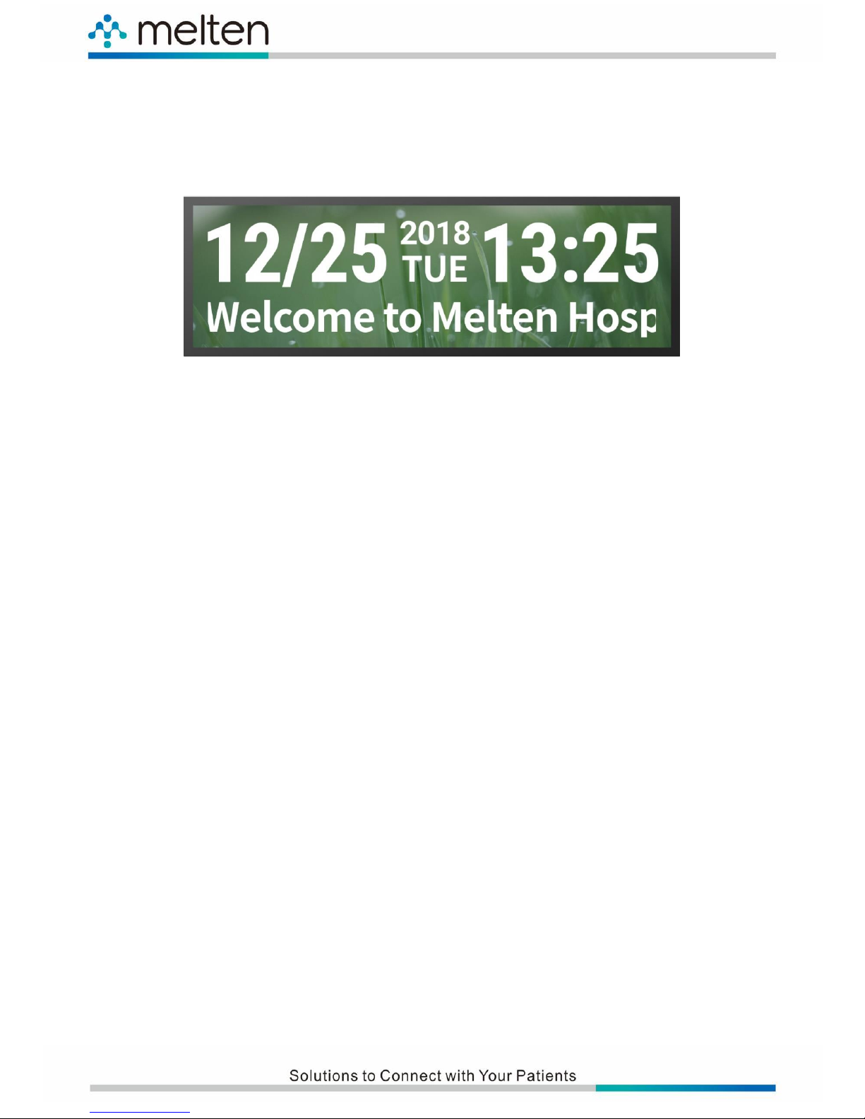
6.5 Double-sided Corridor Display
6.5.1 Corridor Display Exterior View
6.5.2 Corridor Display Functionalities
⚫ Displays the calling ward room number, bed number and bathroom number.
⚫ Call Display Function (4-digit number display) for ward room and bathroom emergency calls
⚫ Caller ID Memory Sequential Display Function: When the lines are busy, it will automatically
memorize the caller IDs and display them in turns. Its displaying and elimination are totally
synchronized with the nurse station host.
⚫ Calling number display and music ring tone indication
⚫ Single-row Display; each set of captions can contain 4 and above characters (4 Chinese
characters, 8 English characters). It supports 10 sets (including the above) of captions
automatic memory sequential display.
⚫ Supports Chinese character entries and display
⚫ It can be used as a caption machine. Each row can display 20 English/Number digits or 10
Chinese characters. Up to 20 lines of captions can be entered.
Page 18
10
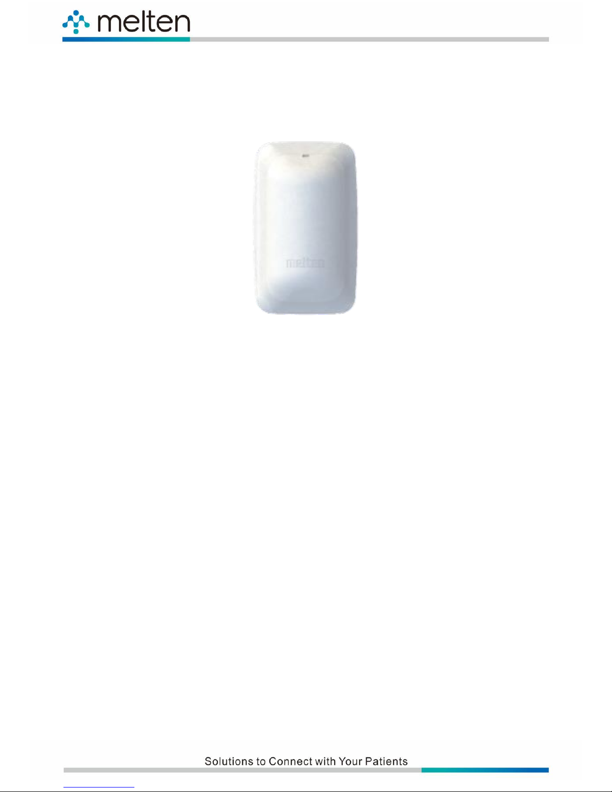
6.6 Dome Light (4 Colors)
6.6.1 Dome Light Exterior View
6.6.2 Dome Light Functionalities
⚫ White square translucent plastic compression molding
⚫ Contains Red and Green indicators
⚫ Bathroom emergency calls will illuminate in red.
⚫ Bedside normal calls will illuminate in green.
⚫ The red and green lights can be individually or simultaneously displayed by
software control (yellow light).
⚫ It will support 7-color display (red, green, blue, light blue, purple, yellow and
white).
Page 19
11
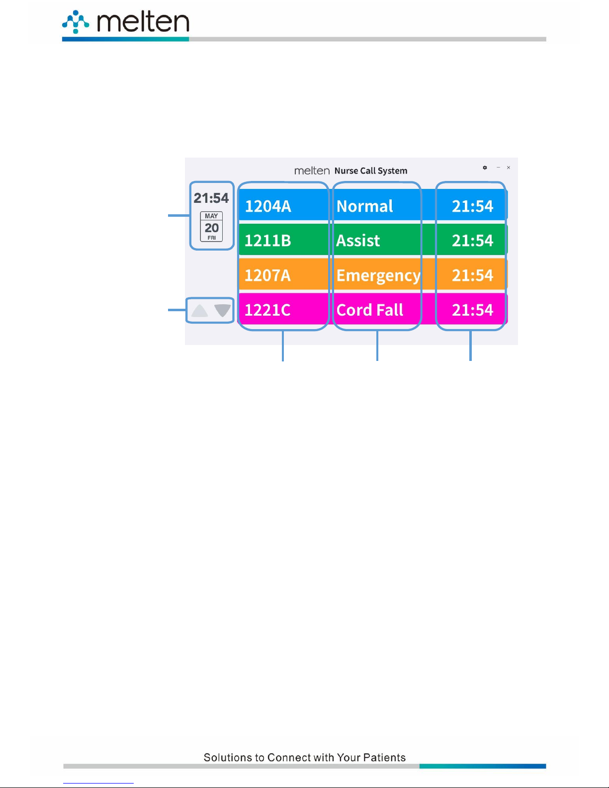
Time/Date
Page Up/Down
Patient Call Time
Call Event Type
Ward Room Number/Bed Number
6.7 Patient Call Display (PCD)
6.7.1 PCD User Interface
6.7.2 PCD Functionalities
⚫ Patient bed number and Information displayed in English and Chinese while
calling
⚫ Automatic sorting by priority and call sequence
⚫ Distinguishes the types of patient calls by different colors, which makes it easy for
the nursing staff to identify the call types.
⚫ Displays the ward room numbers, ward bed numbers and conversation
⚫ Displays the bathroom call of every ward room
⚫ Supports Remote Call Cancel Function
Page 20
12
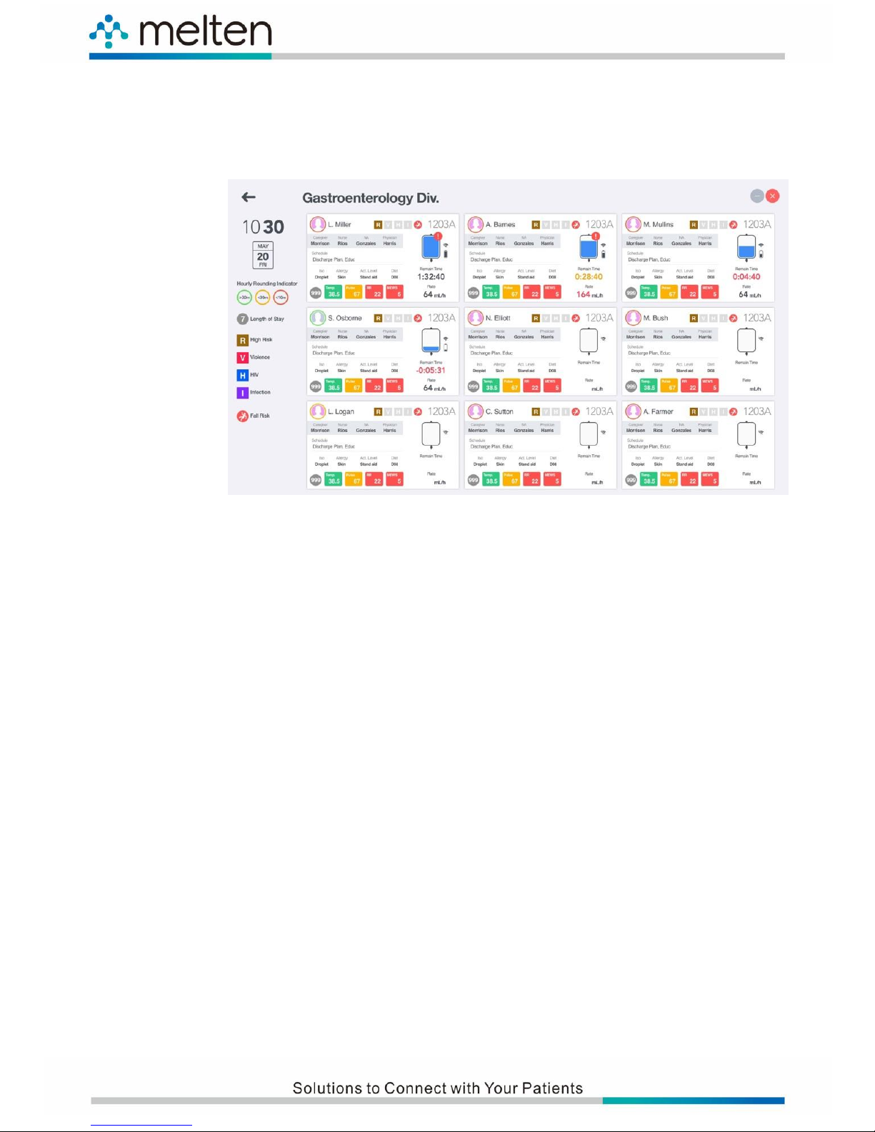
6.8 Nurse Station Dashboard
6.8.1 Nurse Station Dashboard User Interface
6.8.2 Nurse Station Dashboard Functionalities
⚫ Integrated nurse daily workflow
⚫ Melten IoT peripheral information integration
⚫ Reduces medical personnel handwritten errors
⚫ Increases the working efficiency of medical personnel
Page 21
13
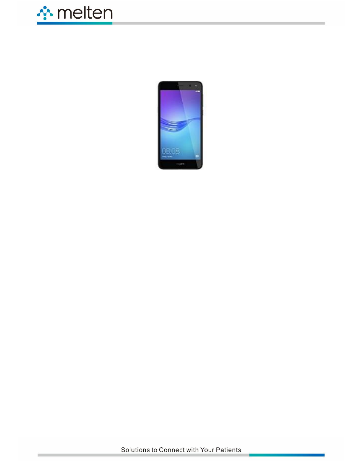
6.9 Smart Phone
6.9.1 Smart Phone Exterior View
6.9.2 Smart Phone Functionalities
⚫ Supports ward room number digital display.
⚫ It’s signal receiving area covers the ward room, corridor and public area of the unit.
⚫ Answering the calls from every ward bed and providing intercommunication capability
Page 22
14
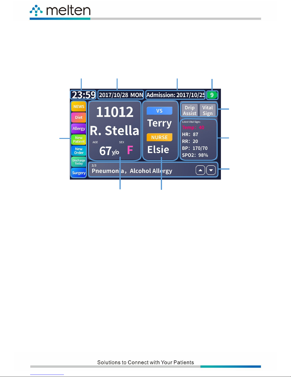
Time
Current Date
Admission Date
Inpatient Days
Latest Vital
Sign Data
Special Needs and
Condition Display
(Switchable)
Special Notes
(Text)
Patient Basic Information
Care Team
Special Notes
7. M2 User Interface Introduction
7.1 M2 User Interface
By manipulating the M2 user interface, the users are able to view or switch the following
information:
⚫ Current Time/Date and Inpatient Days: Displays the current time, date and
inpatient Days.
⚫ Patient Basic Information: Displays the basic information of the patient.
⚫ Care Team: Displays the duty doctor and nurse for the patient.
⚫ Special Needs and Condition Display: Displays the special needs and current
condition of the patient.
⚫ Latest Vital Sign Data: Displays the latest measured vital sign data of the patient.
⚫ Special Notes: This area displays the special notes of the medical treatments for
the patient.
Page 23
15
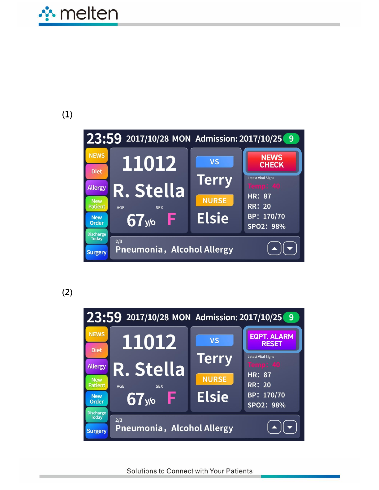
7.2 Switch Flow of the Special Needs and Condition
Display
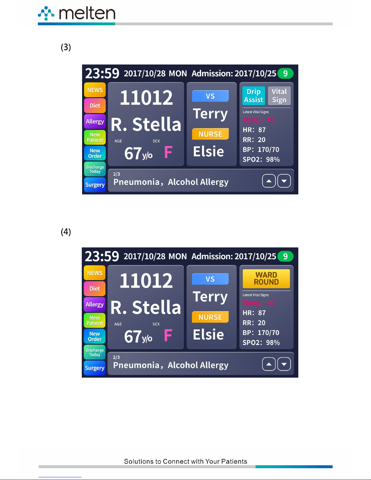
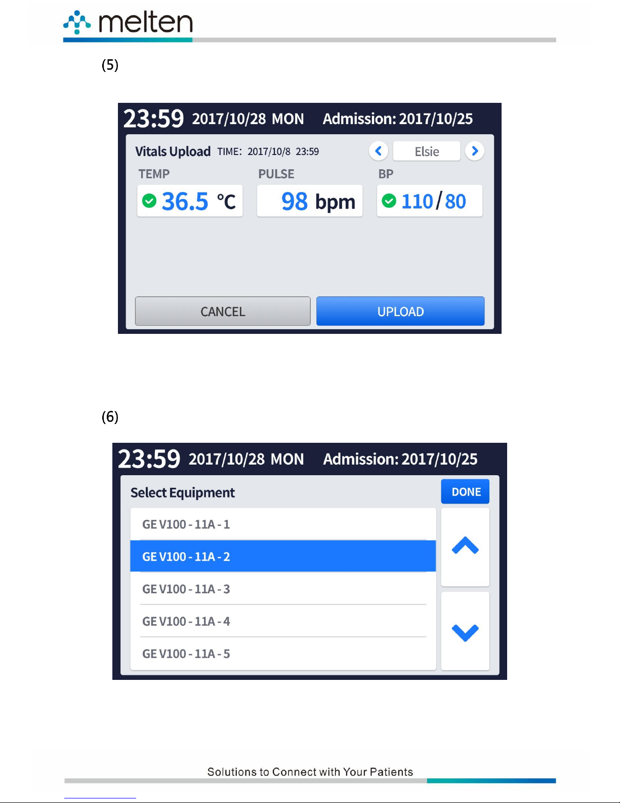
This area displays the real-time needs, current condition or the handling hint of
the patient. The priority and flow sequence are as follows.
News Check (Emergency):
Equipment Alarm Reset:
Page 24
16
Drip Assist:
Ward Round:
Page 25
17
Connected with vital sign measuring equipment and ready to
upload data:
Connected with multiple vital sign measuring equipments:
Page 26
18
8. M2 Nurse Call Module Specifications
Main Module
Platform
MTK7688, W708-32-64C,32MB Flash + 64MB DDR2
Bluetooth Module
eGM-A18, BT4.0 Dual mode USB module
PoE Interface
PoE Ports
RJ-45 x 2 for Power + Data input
RJ-45 x 1 for Data output
Input/Output Ports
Input
Touch Panel, Nurse Call Cord, Microphone, Switch x 4
Output
LCD, LED x 6, Speaker
Environment and Features
Maximum Power Consumption
10 Watts
Power Output Interface
RJ-45 for Power + Data input
Power Requirement
802.3 at 48V~56V POE + Ethernet Source
POE Input Voltage
48V~56V
Operating Temperature
0° to 40° C
Storage Temperature
-10° to 50° C
Operating Humidity
20% to 80% (non-condensing)
Storage Humidity
20% to 80% (non-condensing)
Dimensions ( W x H x D )
310 x 120 x 52 mm
Weight ( g )
665g
Case Material
ABS
Accessory Waterproof Rating
Nurse Call Cord (IP67)
Safety Regulations
FCC, CE, RoHs Compatible
Contact Discharge Voltage
±2KV and ±4KV
Air Discharge Voltage
±2KV, ±4KV and ±8KV
Language Support
English, Traditional Chinese, Simplified Chinese
Operating System
Linux
 Loading...