

Page 1

INDEX
Pages:
Operations and Safety
Frame Size 2
Saddle Adjustment 3-4
Safety Checklist 5-7
Helmets 8
Riding Safely 8-11
Operating Gears and Brakes 12-13
Bicycle Assembly and Tuning
Assembly Instructions 14-21
Folding Instructions 22-24
Bicycle Care
Basic Maintenance 25-29
Wheels and Tires 30-39
Headset 40-42
Brakes 43-45
Drivetrain 46-48
Crank Set 49-52
Chain 52-54
Refl ectors 54-55
Troubleshooting 56-58
Warranty 59
1
Page 2
FRAME SIZE
Choosing the appropriate frame and wheel size is imperative when purchasing a new bicycle. For safe riding the size
of your bicycle should properly match your build.
The melon slice folding bike is provided as a one size fi ts all
bicycle. It can accommodate a height range of 4’8” to 6’3”
in riders. The rider weight limit is 240 lbs.
WARNING:
For safe riding your bicycle should match your
size correctly, otherwise you may lose control
and fall. Ideally there should be a minimum clearance of 25mm between the crotch of the intended rider and the top frame tube of the bike,
while the rider straddles the bicycle with both
feet fl at on the ground.
Clearance over the top of the frame ensures that the rider
can safely stand astride the bike when forced out of the
saddle, such as stopping at traffi c lights. Frame clearance
is not usually an issue with folding bikes as the frame’s top
tube is only 23.5”.
The melon slice is not designed to fi t children. It is not
recommended that children ride this bike.
2
Warranty
Melon Bicycles warrants that any bicycle purchased from
an authorized Melon Bicycle dealer, or from Melon Bicycles directly shall be free from defects in materials and
workmanship for a period of fi ve (5) years from the date
of purchase. This warranty shall extend only to the original owner of the bicycle. All components are covered by
the components manufacturers’ warranties. Paint and
fi nish are covered for one (1) year from the date of purchase by the original owner.
This warranty is void in any instance of abuse, misuse,
neglect, improper assembly, improper maintenance or
from the addition of any components not intended for
the specifi ed model. This warranty shall only be valid if
the bicycle is used for its intended purpose, and shall be
voided by the use of the bicycle for any improper purpose, including, but not limited to, jumping, stunt riding,
riding with heavy loads, or any other non-standard usage.
In the event of any issue, Melon Bicycles may seek to
resolve the problem by replacing the damaged part with
the same or comparable part. Any dealer labor charges
or shipping expenses are the sole responsibility of the
bicycle owner. Correction and/or replacement, in the
manner described herein shall constitute full compliance
with any and all warranties. In no instance shall any warranty extend beyond the purchase price of the bicycle.
THE FOREGOING WARRANTIES ARE EXCLUSIVE AND
INLIEU OF ALL OTHER WARRANTIES WHETHER WRITTEN OR IMPLIED.
The terms of this warranty may change without notice.
59
Page 3
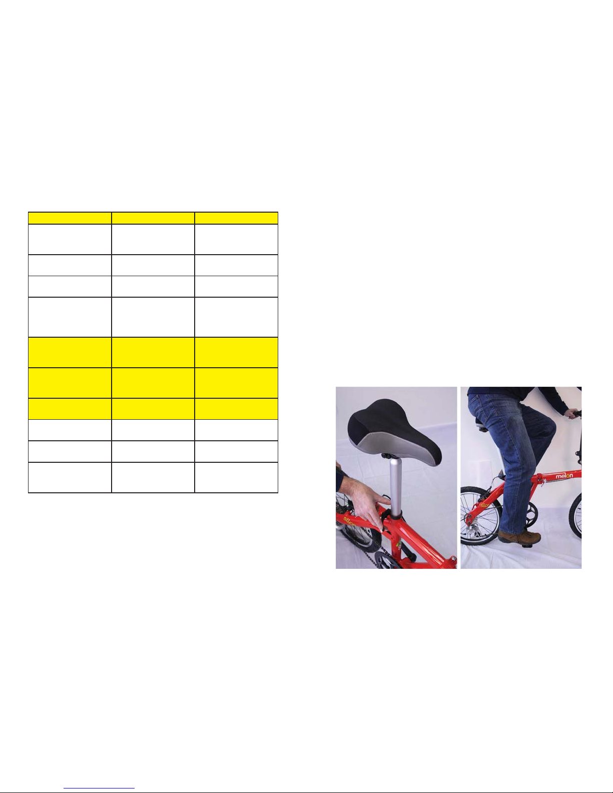
Problem Possible Reason Possible Solution
Chain jumping off
chainwheel sprocket
or chainring
Chainring out of true Re-true if possible or
replace
Chainring loose Secure mounting
bolts
Chainring teeth bent
or broken
Repair or replace
chainring/set
Rear to front derailleur side-to-side
travel out of adjustment
Alter derailleur travel
Incorrect gear shifting Derailleur cables
sticking/stretched/
damaged
Lubricate/tighten/replace cables
Front or rear derailleur not adjusted
properly
Alter derailleurs
Indexed shifting not
adjusted properly
Alter indexing
Steering not accurate Wheels not aligned in
frame
Align wheels correctly
Headset loose or
binding
Adjust/secure headset
Front forks or frame
bent
Consult bicycle
mechanic for frame
realignment
TROUBLESHOOTING (Cont’d)
58
SADDLE ADJUSTMENT
Saddle Height:
When your saddle height is adjusted properly, you should
have a small bend in your knee when your foot is at the bottom of the pedal stroke and you are sitting comfortably. If
you have the saddle height too low, you will lose pedaling
effi ciency and will have to work much harder-we defi nitely
don’t want that. If you have the saddle height too high, you
will be stretching just to pedal and your pelvis will have to
rock side to side with each pedal stroke. Adjust the saddle
height by opening and then closing the quick release lever.
3
Page 4
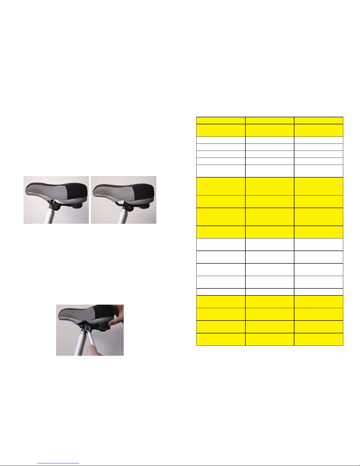
Saddle Tilt:
For the most comfortable riding position, adjust the saddle
to be as level as possible. Newer riders sometimes desire
the saddle to be pointed downward to ease discomfort in
the groin area. This adjustment will make it diffi cult to stay
in the saddle, slightly unsafe, and will cause more problems
for the body in the long run. The melon slice folding bike is
provided with a comfortable well padded seat. We suggest
that you allow yourself time to get acclimated to the seat in
the level position if you are new to riding. Adjust the angle
of the saddle by loosening the nut under the saddle on the
right side of the seat post.
Saddle Front to Back:
This adjustment determines how well balanced you are on
the bicycle. If you move the saddle forward, you will end up
with more of your weight being supported by the saddle itself. If you move the saddle backwards, you will end up with
more of your weight being supported by your arms and
hands. You can experiment to fi nd the sweet spot that is the
most comfortable riding position for you. Adjust the saddle
position by loosening the nut under the saddle on the right
side of the seat post.
4
Problem Possible Reason Possible Solution
Brake arms loose Secure mounting
bolts
Wobbling wheel Axle broken Replace axle
Wheel out of true True wheel
Hub cones loose Tighten hub bearings
Headset binding Alter headset
Hub bearings collapsed
Replace bearings
Knocking or shuddering when brakes
applied
Bulge in the rim or
rim out of true
True wheel or consult
a bike mechanic
Brake mounting bolts
loose
Secure bolts
Brakes out of adjustment
Center brakes and/
or adjust brake block
toe-in
Forks loose in head
tube
Secure headset
Constant clicking
noises when pedaling
Stiff chain link Oil chain
Loose pedal axel/
bearings
Alter bearings/axle
nut
Loose bottom bracket/bearings
Alter bottom bracket
Bent bottom bracket
or pedal axle
Replace bottom
bracket or pedals
Loose crankset Tighten crank bolts
Grinding noise when
pedaling
Pedal bearings too
tight
Adjust bearings
Bottom bracket bearings too tight
Adjust bearings
Chain fouling derailleurs
Adjust chain line
Derailleur jockey
wheels dirty/binding
Clean and oil jockey
wheels
57
Page 5
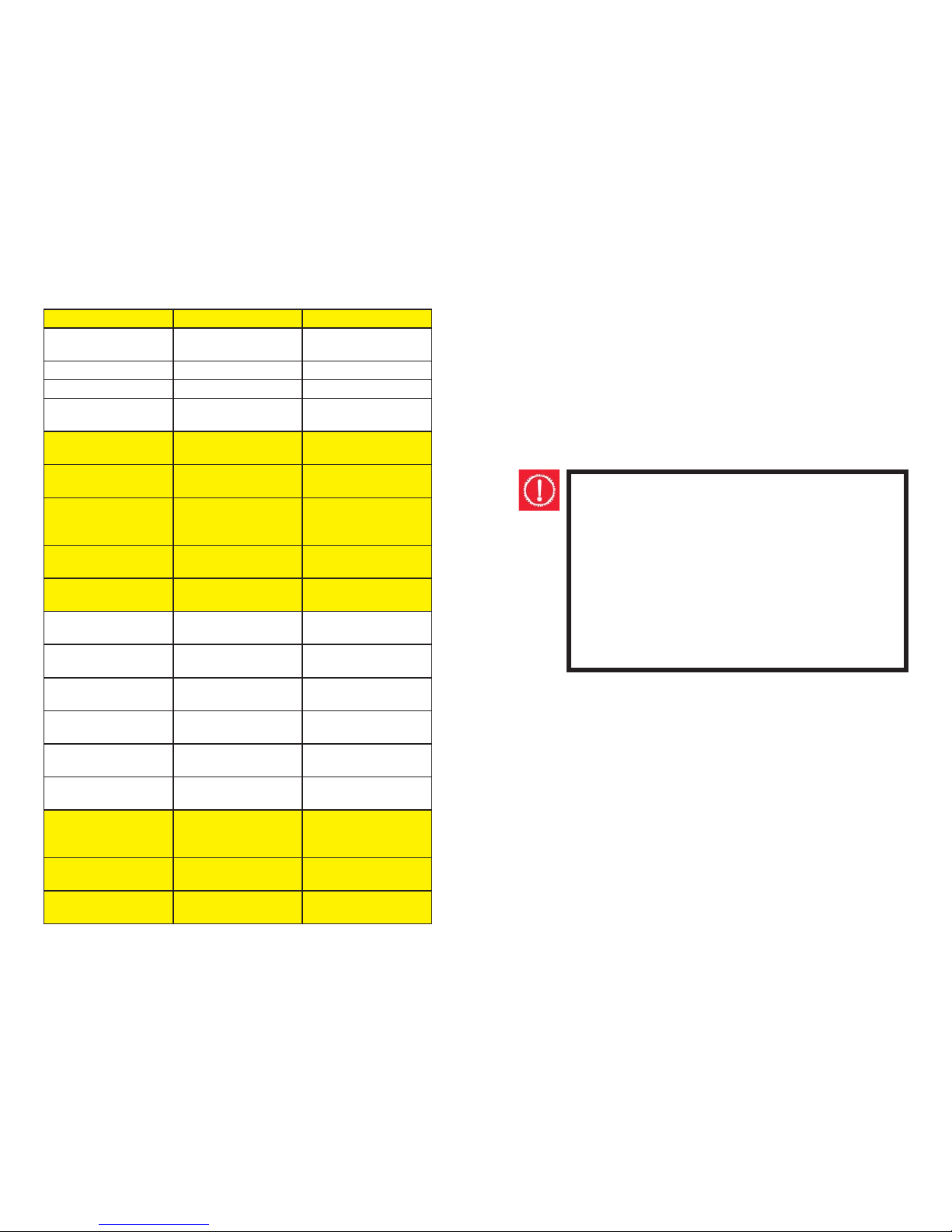
Problem Possible Reason Possible Solution
Slipping Chain Excessively worn or
chipped chainring
Replaice chainring
Chain worn/stretched Replace Chain
Stiff link in chain Oil or replace link
Non compatible
chain/chainring
Consult a professional
bicycle mechanic
Brake not working
correctly
Brake blocks worn
down
Replace brake blocks
Brake blocks/rim
greasy,wet or dirty
Clean blocks and rim
Brake cables are
binding/stretched/
damaged
Clean/adjust/replace
cables
Brake levers are binding
Alter brake levers
Brakes out of adjustment
Center brakes
Frequent punctures Inner tube old or
faulty
Replace inner tube
Tire tread/casing
worn
Replace tire
Tire incompatible to
rim
Replace with correct
tire
Tire not checked after
previous puncture
Remove any sharp
objedts from tire
Tire pressure too low Infl ate tire to correct
pressure
Spoke protruding into
rim
File down spoke
When the brakes are
applied they squeal/
squeak
Brake blocks worn Replace brake blocks
Brake blocks/rim
greasy,wet or dirty
Clean blocks and rim
Brake block toe-in
incorrect
Correct block toe-in
TROUBLESHOOTING
56
SAFETY CHECKLIST
Safety checks are an important part of any ride. In conjunction with the recommended maintenance in this manual
it is also suggested that a thorough inspection should be
undertaken fortnightly, tightening all nuts and bolts, replacing worn and damaged parts and ensuring all components
are in their correct positions.
WARNING:
Body parts and other objects should be kept
clear from the moving components of the bicycle
when in use, such as the spinning wheels and the
moving chain. When riding always wear appropriate footwear – i.e. shoes that will grip the pedals
and no sandals. Refrain from jumping with your
bike. Jumping puts enormous stress on many
components of your bicycle, especially your front
fork.
Prior to every ride please complete the following safety
checks:
1. Brakes
• Check front and rear brakes are working correctly
• Check brake control cables for wear and ensure they are
oiled and properly adjusted
• Check brake control levers are lubricated and securely
fastened to the handlebar.
• Check brake shoe pads for wear and their positioning in
relation to the rims
5
Page 6
2. Wheels and Tires
• Check tire pressure is as recommended according to the
specifi cation displayed on the tire sidewall
• Check tires for tread and ensure they do not have any
bulges or excessive wear.
• Check all wheel spokes are fi rm and are intact
• Check rims run true and are without any obvious buckles
or kinks
• Check that axle nuts are tight. For bicycles equipped
with quick release axles, ensure locking levers are tensioned appropriately and in the closed position.
3. Saddle
• Check the clamp underneath the saddle is fi rmly secured
to the saddle post
• Check frame clamping mechanism is tightly fastened
• Ensure that the minimum insertion mark cannot be seen
on the saddle pillar
4. Steering
• Check that the handlebar and stem enable correct
steering and are properly adjusted and tightened
• Check that the setting of the handlebars is correct in
relation to the forks and the direction of travel
• Check the head set locking mechanism is appropriately
fi xed and fastened
• If handlebar extensions are fi tted check they are positioned and secured correctly
• Ensure the minimum insertion mark cannot be seen on
the handlebar stem
• Ensure the ends of the handlebars and bar ends are
covered or capped.
5. Chain
• Check the chain is lubricated, clean and runs freely
• In wet or dusty conditions service the chain more frequently
6
WARNING:
The refl ectors and the refl ector mounting brackets
must not be removed from your bicycle. Doing so
may reduce your visibility to other road users, potentially jeopardizing your safety. Serious injury or
death may result if you are hit by another vehicle
unable to see you.
WARNING:
Refl ectors should always be used in conjunction
with powered lighting when riding at night, at
dawn, dusk, or at any other time in poor visibility.
Failure to do so is dangerous and may result in
serious injury or death.
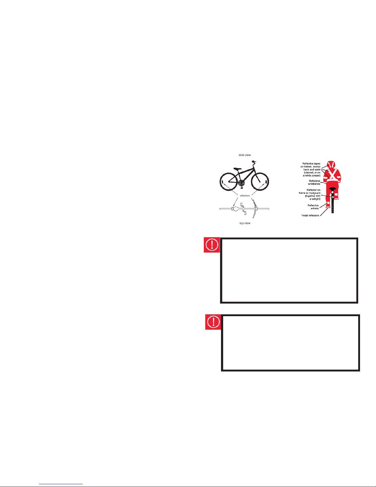
When riding at night, in addition to the refl ectors, the
bicycle should also be equipped with powered lights. Refl ective tape on the rider’s clothing is also recommended to
increase visibility.
55
Page 7

REFLECTORS
The refl ectors fi tted to your bicycle are not only an important safety feature, but a legal necessity as well. Your bicycle should come equipped with one white (front), one red
(rear), and two orange (wheel) refl ectors. Each pedal should
also have two orange refl ectors fi tted.
As a part of your bicycle maintenance ensure that all refl ectors are clean, intact and securely fastened. The front and
rear refl ectors should be vertically aligned, and the wheel
refl ectors should be secured opposite the valve within
75mm of the rim.
To install a chain on a derailleur geared bicycle:
• Thread the chain around the chainwheel, rear sprocket
and derailleur cage with the rivet facing away from the
bicycle.
• Bring the two ends together within the special tool and
punch the rivet into place. Take care not to push rivet
too far through the side plate. Derailleur geared bicycles
can now be fi tted with some new types of chains that do
not require special tools to remove or replace. Instead,
a new, special, disposable connecting link is used every
time you disassemble the chain. For further details on
these particular chains, including installation guidelines,
refer to the manufacturer’s specifi c instructions.
54
6. Bearings
• Check headset, wheel bearings, pedal bearings and bottom bracket bearings
• Check all bearings are oiled, run smoothly and show no
signs of excess movement, grinding or rattling
7. Cranks and Pedals
• Check cranks are securely fastened to the axle and are
straight
• Check pedals are properly and fi rmly attached to the
crank
8. Derailleurs
• Check the rear mechanism is operating appropriately
• Check control levers are securely anchored
• Check derailleurs, control cables and shift levers are suffi ciently lubricated
• If the gear components come with a separate, specifi c
manual, refer to this for further information
9. Frame and fork
• Check that the frame and fork are straight and intact.
• Replace if either is bent or broken.
10. Safety & Accessories
• Check that all refl ectors are attached correctly and visible
• For riding at night, fi t fully functioning dynamo or battery powered lights
• Check that the bell is fully operational
• Check all additional components on the bike are appropriately secured and functioning
7
Page 8
When riding your bicycle it is recommended that you always
wear an appropriately fi tting Country Standards Approved
bicycle helmet.
A bicycle helmet must:
• Carry the Country Standards Approved
• Fit properly
The helmet should be:
• Well ventilated
• Comfortable
• Lightweight
HELMETS
WARNING:
The wearing of helmets is mandatory in many
areas.
Noncompliance may result in an enforceable penalty
RIDING SAFELY
General Rules
• The same road rules used for vehicles apply to cyclists.
Obey the road rules at all times, such as giving way to
pedestrians, and stopping at red traffi c signals
• Notify the Road Traffi c Authority in your state if further
information is required.
8
To remove a chain on a derailleur geared bicycle:
• Fit the rivet tool so that the punch pin is centered over
any one of the chain rivets.
• Push the rivet almost all the way out, then back out the
punch and remove he tool.
• Holding the chain on both sides of the punched rivet,
bend it slightly to release the link from the rivet.
Adjustment and Replacement
The chains on derailleur geared bicycles are automatically
tensioned by the rear derailleur making manual adjustment
of the chain unnecessary. The chains on derailleur geared
bicycles are narrower, meaning a special tool is needed to
complete any of the procedures.
Check that all links of the chain move freely. Replace the
chain if it appears stretched, broken or causes problems
when changing gears.
53
Page 9

CHAIN
Inspection and Lubrication
Regular inspection and maintenance of your chain is vital to
guard against premature wear. At least monthly, or after riding in wet, muddy or dusty conditions, the chain should be
cleaned and lightly oiled. Any excess oil should be removed
and care taken to ensure the lubricant does not come into
contact with the tires or rim braking surfaces.
Lubrication and Replacement - Cartridge Bottom Bracket
Freeplay cannot be removed from a cartridge bottom
bracket. It is a sealed unit and is designed to be replaced
as an entire unit when it is worn out. Once the cranks have
been removed a specifi c extraction tool is required to remove the cartridge bottom bracket. Consult your specialist
bicycle dealer for further advice regarding this process.
52
• Ride on the right side of the road and never against the
traffi c.
• Take extra care when attempting to overtake other vehicles and at intersections.
• Indicate intended actions, such as turning or stopping,
by using appropriate hand signals.
• Ride predictably and in a straight line.
• Always ride defensively. You may be diffi cult to see to
other road users.
• Closely observe the riding terrain. Avoid obstacles
such as pot holes, gravel, wet road markings, oil, curbs,
speed humps and drain grates.
• Be alert. Watch for such things as motorists opening
doors or backing out of concealed driveways.
• Sound your bell for a warning when required.
• Train and tram tracks should be crossed at a 90 degree
and preferably walk your bicycle over.
• Know how your bicycle operates. Practice braking, gear
shifts and if fi tted, using toe clips and straps.
• Always apply the rear brake fi rst, then the front when
braking. The front brake is more potent and if it is not
used properly you may lose control and fall.
• Allow reasonable space between yourself and other
vehicles and objects when riding and stopping. Take
note of weather conditions and its possible impact on
safe braking distances. e.g.. Wet riding surfaces increase
braking distances.
• Use leg clips or elastic bands if you are wearing loose
trousers to stop them catching in the chain.
• Ensure your vision or control of the bicycle is not obstructed by any items you may be transporting.
• Do not use items that may impede your hearing. e.g.
headphones
9
Page 10
Wet Weather
• Ride more cautiously in wet weather. Avoid sudden
braking, slow overall riding pace and approach corners
more carefully.
• Brake sooner, stopping distance increases in wet conditions.
• Remember pot holes and slippery surfaces such as line
markings and tram tracks all become more hazardous in
the wet. Try to avoid where possible.
• Cornering traction will also be reduced in wet weather.
Night Riding
• Wear refl ective and light colored clothing.
• Refl ectors should be fi tted correctly to the bicycle and
clearly visible. Riding in the dark should never be undertaken without fully operational front and rear bicycle
lights. The use of bicycle lights is mandatory for night
riding in most Australian States.
• Attach a fully operational lighting set. Lights should have
a white front lamp and a red rear lamp.
• Use a fl ashing rear light to improve visibility.
• Charge batteries if battery powered lights are to be
used. Check wiring connections for dynamo powered
lights.
• Avoid riding at night if possible. If not, slow down and
opt for familiar roads with street lighting when able
On Road Off Road
• The melon slice is designed for on road riding. Extra
care should be taken when riding on dirt or gravel surfaces.
10
Three Piece Crank Replacement
1. Place the crank arm onto the axle.
2. Use a soft mallet to gently tap the crank arm.
3. Reattach the washer and secure the fl ange nut or bolt
securely to a torque of 27Nm.
4. Replace the dust cover.
After fi tting new three piece cranks some additional
maintenance is required as components can become
loose with use. The following adjustments should
be made after several hours of riding, and repeated
two or three times after further use. There after the
cranks should remain secure.
1. Remove the dust cap.
2. Gently tap the crank arm with a mallet.
3. Re-tighten the fl ange nuts, and refi t the dust caps.
51
Page 11
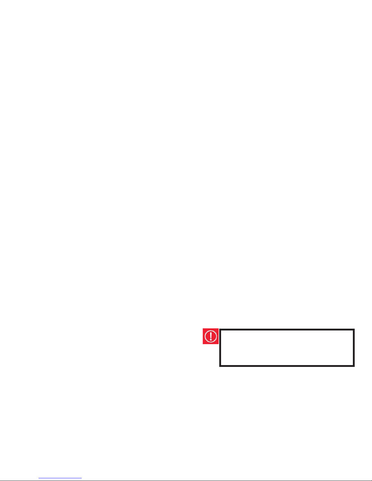
Lubrication and Adjustment – Three Piece Cranks (Cotterless Cranks)
To adjust:
• Turn the lockring on the left side anti-clockwise.
• Turn the adjusting cup until appropriately set.
• Carefully re-fasten the lockring without disturbing the
cup adjustment.
To disassemble:
1. Remove the cranks from the axle.
2. Turn the left side lockring anti-clockwise and remove.
3. Turn the adjusting cup anti-clockwise and remove.
4. Remove the left ball retainer and slide the axle out of
the frame to the left.
5. Turn the right side fi xed cup anti-clockwise and remove,
as well as the right ball retainer.
Once the crank is dismantled clean all bearing surfaces and
the ball retainers and check for wear. Replace any damaged
parts and pack grease into the ball bearing retainers. Reassemble the crank in the reverse order of the procedure
listed above.
Three Piece Crank Removal
To remove Cotterless cranks you will need to use a specifi c removing tool. Follow the outline below to guide you
through the process.
1. Use a coin or a screwdriver to remove the dust cap.
2. Remove the fl ange nut or bolt and washer after loosening.
3. Attach the removing tool into the crank and tighten.
4. Turn the screw bolt until the crank comes away from the
axle.
50
Pedaling Technique
• Place the ball of your foot on the centre of the pedal.
• Ensure your knees are parallel to the bicycle frame when
pedaling.
• Keep your elbows slightly bent. This will help to absorb
shock.
• Learn how to use the gears correctly
Hill Technique
• Prior to a climb, gear down and continue gearing down
as necessary in order to sustain pedaling speed.
• By standing up on your pedals you will be able to generate greater power from each turn of the pedal. This is
useful if you are straining and are using the lowest gear.
• Use the high gears on a descent to prevent rapid pedaling.
• Take extra care when descending. Do not exceed a comfortable speed and maintain control.
Cornering Technique
• Before entering a corner brake slightly and begin to lean
your body into the corner.
• The inside pedal should be held at the 12 o’clock position and the inside knee angled slightly in the direction
you are turning. The other leg should be kept straight.
• Avoid pedaling through fast or tight corners.
As suggested by the Consumer Affairs Department
riding bicycles with small wheel diameter at excessive
speeds can lead to instability and is therefore not recommended.
CAUTION:
When riding downhill never take your hands off
the handlebars, or feet off the pedals
11
Page 12
OPERATING GEARS AND BRAKES
Derailleur Gears
Derailleur gears are the most common type of gear systems used on bicycles. They are the changing mechanism
used to move the drive chain up and down a series of cogs
or sprockets (the cluster or cassette stack) at the rear of
the bicycle and across the chainwheel at the front of the
bike (if fi tted). Multispeed bicycles today can range form
5-6 gears to as many as 30. Rear derailleurs are fi tted to all
multispeed bicycles while front derailleurs are only present
on those bicycles with the higher number of gears. Gears
enable the cyclist to select the most appropriate pedaling
resistance best suited for the riding conditions. The more
gears fi tted to the bicycle the greater choice available to
the rider.
Operating Principles
Although the number of gears present on multispeed bicycles varies greatly, how the gears function remains the
same. The right shifter works the rear derailleur and the left
shifter works the front derailleur. If the pedals are stationary or rotating backwards, gears cannot be changed. They
can only be altered when pedaling forward. To achieve a
successful gear change, either moving up or down in gears,
the pedaling pressure must be relaxed. Failure to ease the
pressure when changing gears may result in bicycle damage
or could even cause the rider to lose control. If a rubbing
sound is detected after attempting to alter gears, adjust the
shifter until the sound ceases. Generally the lower gears are
for ascending hills and the higher gears are for descending.
12
WARNING:
Never attempt to force a pedal into a different
sized bicycle crank.
CRANK SET
Inspection and Maintenance
Every month the crank set should be checked to ensure that
it is properly adjusted.
For Three Piece Cranks:
• Check that the crank axle nuts are tight.
• Adjust the bottom bracket bearings as necessary.
• Remove the chain and test for crank movement on the
axle by attempting to move the cranks from side to side
with your hands. Only very slight movement in the bottom bracket should be noted.
• Rotate the cranks. Adjust and oil if they do not spin
freely or a grinding noise is detected.
• Check the chainrings for any broken teeth, and clean off
any excess dirt and grease.
CAUTION:
Always ensure that your Three Piece cranks are
fi rmly secured before riding. Riding with loose
cranks is potentially hazardous to both the rider
and condition of the crank arms.
49
Page 13
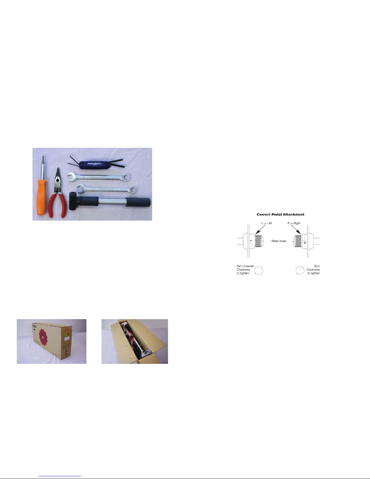
Attachment
Each pair of pedals has a specifi c right and left pedal. It is
important that a pedal is never forced into the incorrect
crank arm as the thread is different for the two pedal sides.
The right pedal, as indicated by the “R” stamped on the
end of the axle, screws into the crank on the chainwheel
side of the bicycle in a clockwise direction. The left pedal
is marked with an “L” on the axle, and it is attached to the
other side in an anti-clockwise direction.
To attach, place the pedals into the correct crank arm and
wind on by hand as tightly as possible in the appropriate
direction. Use a 15mm wrench to fasten more securely.
Removing a pedal is the reverse process of attaching. The
right pedals needs to be turned anti-clockwise and the left,
clockwise.
Before fi tting any new pedals ensure that the axle thread
size is compatible with the cranks on your bicycle. The two
types of cranks available each have different axle threads.
Cranks that are a one piece design have no separate axle
and are compatible with pedals that have a 1/2” thread.
Three piece crank sets with a separate left and right crank
use a slightly larger 9/16” thread.
48
Hand Grip Shifters
Hand grip shifters are built into the hand grip and attach to
the handlebars. Unlike other types of shifting mechanisms
the hand grip shifters mean you do not need to change
your hand position to select different gears. The rider just
simply twists forwards or backwards dependent upon their
gear selection. By twisting the right shifter toward you, a
lower gear is chosen as a larger rear cog is selected. Twisting this shifter away from you has the opposite effect; a
higher gear is selected as a smaller rear cog is engaged.
Turning the left shifter forward or away from you activates
a smaller, front chainwheel, and a larger, front chainwheel
is engaged by twisting it backwards. The number of gear
changes to occur at any one time corresponds with how
many turns are made of the shifter.
Brakes
V-brakes are activated by pulling of the brake hand levers
located on the bike’s handlebars. The right brake lever
activates the rear brake and the left hand lever activates
the front brake. Always apply the rear brake fi rst and then
slowly add pressure to the front brake.
WARNING:
Applying the front brake fi rst or with a disproportionate amount of pressure can cause the bike
rider to fl ip over the front wheel.
13
Page 14
BICYCLE ASSEMBLY AND TUNING
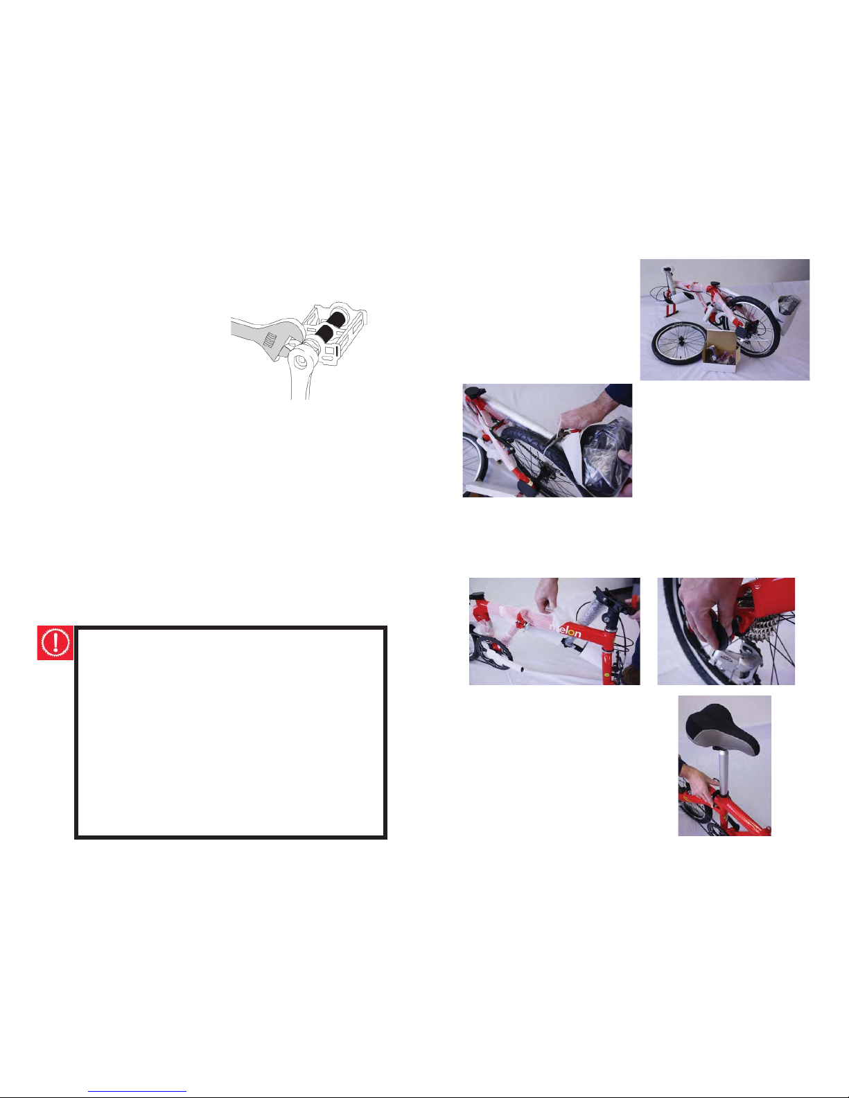
You will need the following tools for the assembly and maintenance of your melon:
Before you unpack your new melon, make sure to keep the
box in the upright position. Open the box from the top.
Assembly Instructions:
14 mm wrench
15mm wrench
Philips screwdriver
Hex allen wrenches:
2mm,2.5mm,5mm, and 6mm
Needle nose pliers
Tire pump
14
Inspection
Every month the pedals should be inspected. Check that:
• Pedals are securely fastened into the cranks. Loose
pedals are a potential hazard for both the rider and the
integrity of the cranks.
• Pedal bearings are adjusted correctly. Alter, grease or
replace if any roughness or looseness is detected in
the pedal bearings when the pedals are moved up and
down, laterally or rotated by hand.
• The front and rear pedal refl ectors are clean and fi rmly
attached.
• If toe clips are fi tted, ensure that they are fastened
tightly to the pedals.
Lubrication and Adjustment
The maintenance your pedals need will depend upon
whether or not they can be disassembled to enable access
to the internal bearings and axle. If they cannot be disassembled, every six months a small amount of oil should be
injected onto the inside bearings of pedals. Pedals that can
be fully disassembled should have the bearings removed,
cleaned and greased every six to twelve months. However,
due to the complexity of this task it is recommended that it
be completed by a professional
bicycle mechanic.
47
Page 15
DRIVETRAIN
The drivetrain consists of the
pedals, chain, chainwheel,
crank set, and freewheel.
These are all the components of the bicycle that
transmit power to the rear
wheel.
Pedals
There is a vast range of pedals available, designed for many
different uses. Pedals fi tted with toe clips and straps aim to
make the pedaling process easier for the rider. The toe clips
and straps ensure the cyclist’s feet stay correctly positioned
and cause a pulling force, as well as a downward pressure,
to be generated on the pedals. To get the full benefi t of
these pedals it is recommended that the rider wear cycling
shoes especially designed for use with toe clips. Consult
your bicycle dealer for instruction on how toe clips and
straps operate.
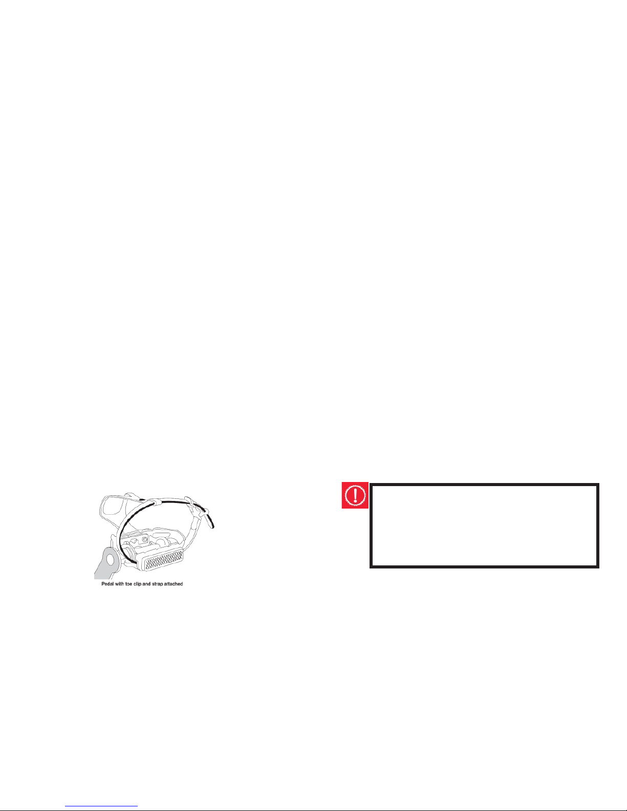
WARNING:
Pedals fi tted with toe clips and straps require a
certain level of skill to operate safely. Riders should
repeatedly practice using such pedals in areas free
from traffi c, hazards or obstacles, until operation
becomes a refl ex action. Failure to do so could
result in the cyclist losing control of the bicycle and
falling. It is also recommended that the straps be
kept loose initially and gradually tightened as the
rider’s skill in using the pedals increases. However,
toe straps should never be tight when riding in
traffi c.
46
You will fi nd three pieces inside: the bike, the front tire,
and a box with pedals and
refl ectors.
Cut the plastic ties holding
the seat post to the frame
and the piece of foam to the
stem joint.
Remove the foam wrap and cardboard from the bikes
frame. Take off the plastic guards around the top of the
seat tube, both sides of the rear axle, and the bottom of
the front fork.
Spread some grease around the
bottom outside of the seat tube.
Insert the seat post into the seat
tube and tighten the quick release
lever.
15
Page 16
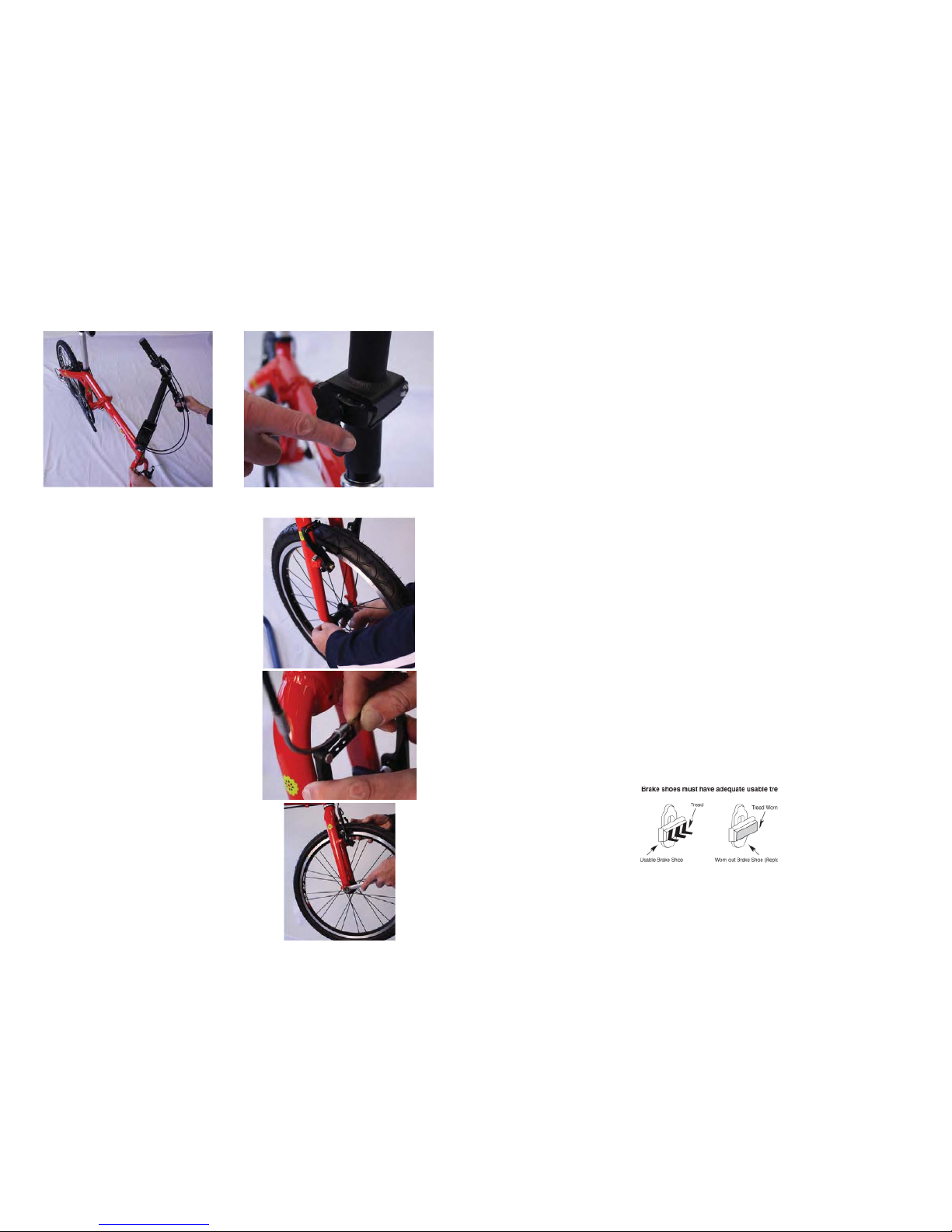
Raise the stem and tighten it in place by turning the stem
joint.
Release the front brake and
slide the front tire into position. Loosen the bolts on
either side of the front wheel
axle and push the axle into the
top of the fork slots fi rmly. At
the same time, you will need
to make sure that the wheel is
properly centered in the fork.
When you think you have got it
right, tighten the axle nuts with
a 15mm wrench (turn clockwise
on both sides). Spin the wheel
to make sure that it is properly
centered in the fork and does
not wobble. If the wheel is not
centered, loosen the nuts and
try again. Re-attach the front
brake when fi nished.
16
Brake Shoe Replacement
Check your brakes shoes monthly for any indication of wear.
If the pads are worn past the “wear line” indication (See
diagram), the brake shoes need to be replaced. Always replace the brake shoes in pairs – never one side only.
For replacement, disconnect the holding mechanism specifi c to your brake type -i.e. a hexagonal nut or an Allen
screw arrangement, or a combination of both. Remove the
worn brake shoes paying careful attention to the order and
position in which the various curved washers and spacers
are attached. Fit the new brake shoes, and tune the angle
and the clearance to the rim as required. Typically, before
the rim clearance can be adjusted the control cable anchor
bolt needs to be loosened and then the cable adjusters
fasten and the cable tensioned. (Refer to the Installation/
Adjustment section relevant to your brake type for detailed
instructions.) Once the adjustments are complete, securely
fasten the brake shoes in place and test that the brakes
are functioning correctly. Do not ride the bicycle until the
brakes are working effectively.
45
Page 17
Brake Inspection
The brake levers and the brake pads are the two main
components that need to be checked to ensure your brakes
are functioning effectively. Positioning of the brake levers
should be checked to ensure they can be easily reached by
the rider’s hands and alterations made as necessary. Some
brake levers have a screw adjuster to change the distance
between the lever and the handlebar grip. This should be
checked for tightness every three months. Similarly, at least
every three months the brake levers should be tested to
ensure they do not move on the handlebars and each brake
lever moves freely when compressed.
Prior to every ride inspection of the brake pads is recommended. The brake pads must be centered, with approximately 1.5mm – 2mm clearance between each pad and
the rim when the brakes are not in use. Test that when the
brakes are applied that the brake pads squeeze the rims
suffi ciently to stop the bike. Replace the brake pads if the
grooves or pattern has worn away from the surface. Ensure
that the brake pads are fi rmly secured before every ride
and at least every three months check the tightness of the
numerous bolts and nuts supporting the brake pads.
44
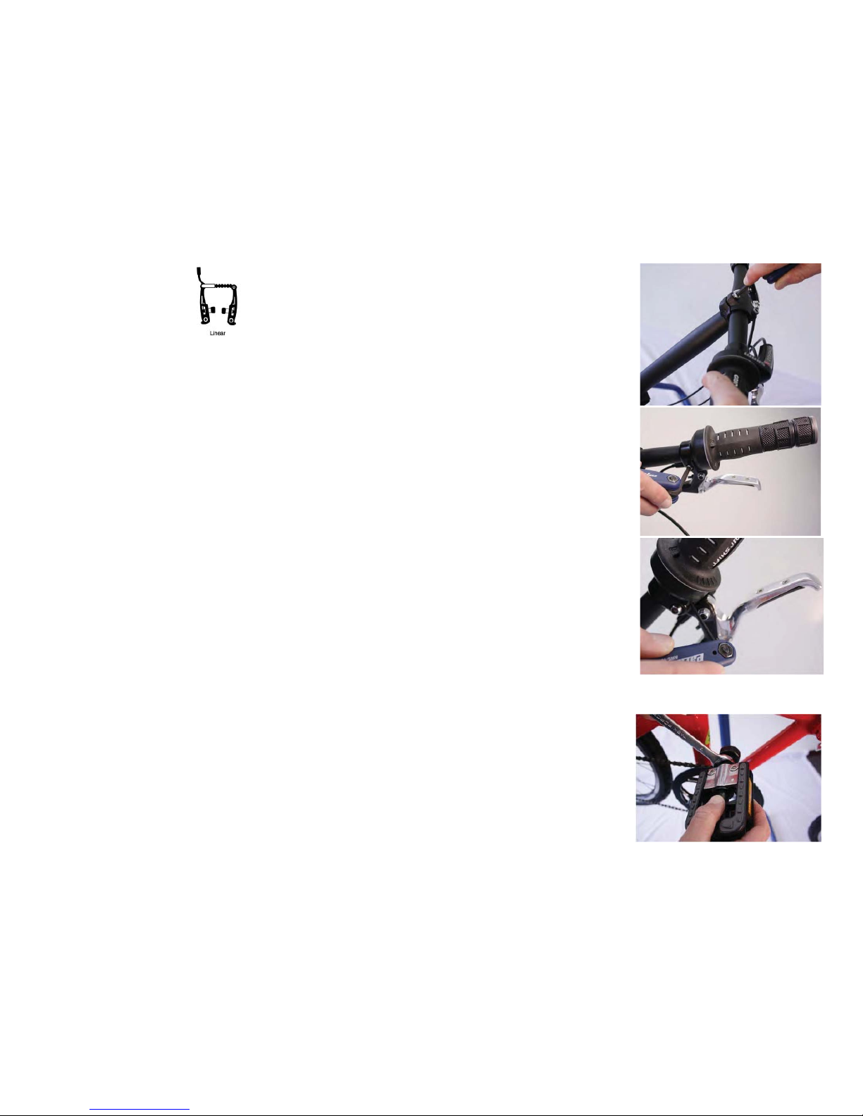
Check the positioning
of the handlebars. The
sweep (handlebar curve
towards the seat) should
be coming straight
back, not upwards or
downwards-unless you
like it that way? To adjust
the angle of the handle
bars, loosen the (2) 5mm
adjustors at the top of
the stem. To adjust the
angle of the (2) brake
levers; loosen the 5 mm
adjustor under each lever.
To adjust the angle of the
SRAM grip shift indicator,
loosen the 2.5mm adjustor.
Install the pedals into
the crank. Each pedal is
labeled for left or right
side (R,L) on the end of
their bolts. Use a 15mm
wrench to fi rmly tighten
the pedals by moving the
wrench toward the front
of the bike on both sides.
17
Page 18
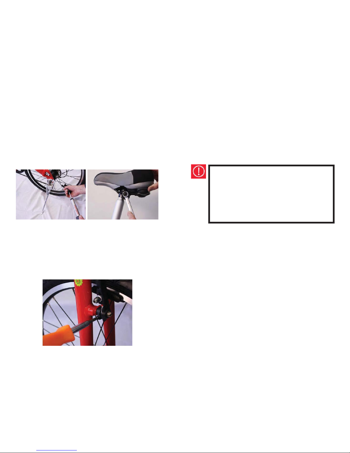
Infl ate the tires to 50-55 psi (tires have schraeder valves).
Adjust the saddle height and positioning. Attach the white
refl ector to the handlebars and the (2) yellow refl ectors to
the spokes of each wheel. The red refl ector has a mounting
bracket which snaps onto the refl ector at one end and bolts
to the cross frame piece just above the rear tire (please see
the mounting hole in this frame piece) on the other end.
Proceed to our tuning section to fi ne tune the performance
of your melon bicycle.
The brake pads should be 1/16-1/8" away from the rim
(closer for faster stops, furtheraway for slower, more controlled stops).Tighten the screw on the side of the brakehousing clockwise to increase the distance and loosen the
screw counterclockwise toshorten the distance.
Brakes
18
BRAKES
For safe riding it is crucial that your bicycle’s brakes function correctly. With use the bicycle’s brake pads wear and
the control cables stretch. Consequently, prior to every ride
the brakes should be inspected and adjusted as necessary
to ensure proper operation.
WARNING:
A bicycle should never be ridden unless the
brakes are working correctly. Take care when using the front brake. Applying it abruptly or excessively may throw the rider over the handlebars,
potentially causing serious injury or death.
43
Page 19
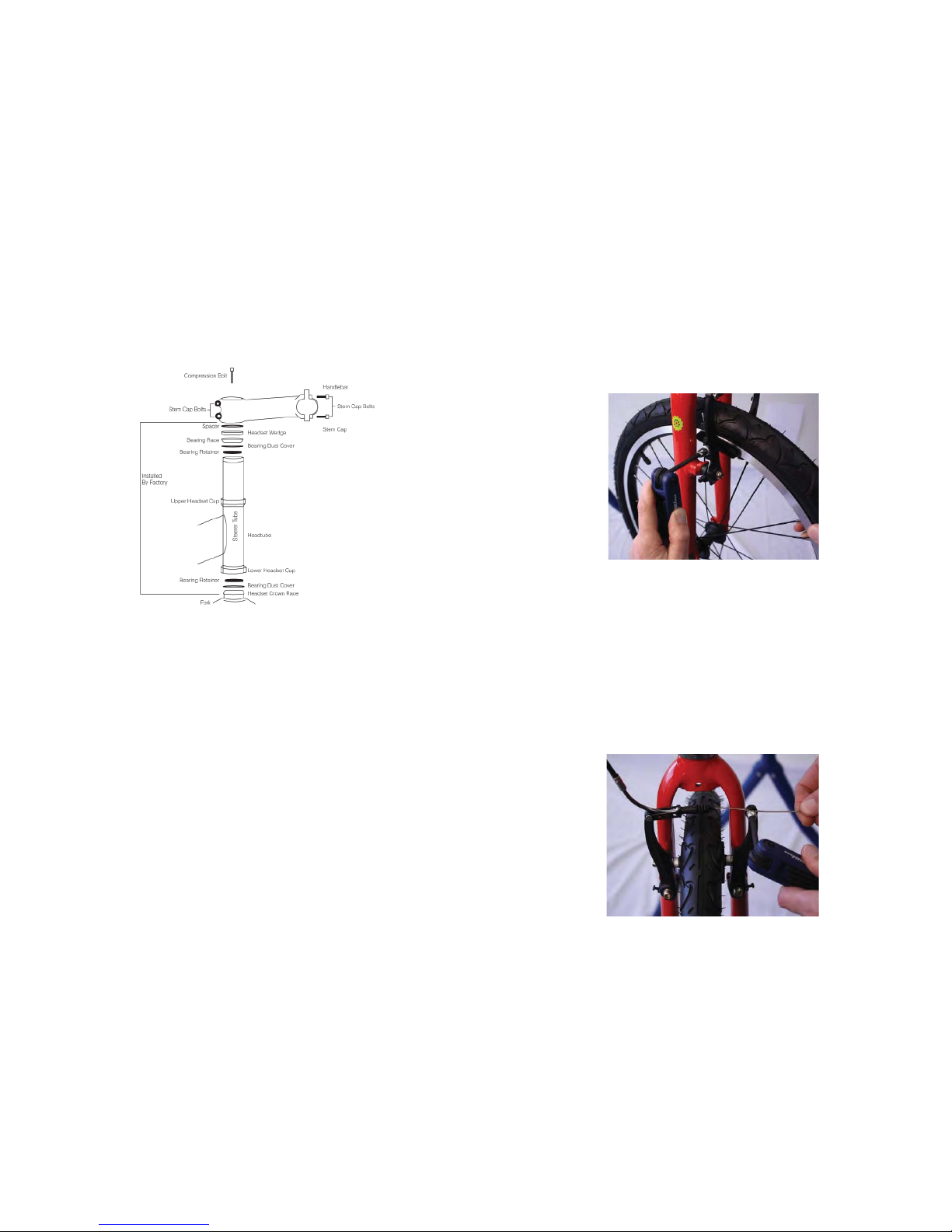
Lubrication and Attachment of An ‘Ahead Set Stem To
The Fork Diagram:
42
The brake pads should be lined up on the rim when the
brake levers are pulled. They should not make contact with
the tire or be positioned too far towards the center of the
wheel. Loosen the 5mm adjustor on the outside of the
brakes to reposition the pads.
Adjust the response of the brakes by loosening the locking
wheel and then loosening or tightening the barrel adjustor
(counterclockwise increases cable tension, clockwise reduces cable tension). When the response is what you want,
tighten the locking wheel back in place. If greater adjustment is needed, loosen the adjustor that holds the brake
cable on one side of the brakes. Move the cable in or out
and tighten the screw again.
19
Page 20
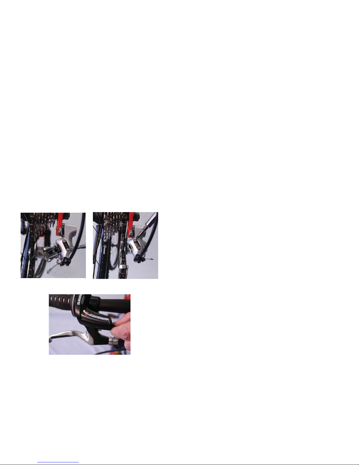
Have someone hold the rear wheel in the air (or hang the
seat from something) so that you can move the pedals
freely with your hand. Move the grip shifter to gear position
1 and apply gentle pressure with the shifter to see if the
chain will move off the largest sprocket towards the spokes.
If the chain moves towards the spokes at all, tighten (clockwise) the bottom screw (marked L) on the back of the rear
derailleur until the chain remains fi rmly on the sprocket. Do
the same thing with the shifter in position 8 and the chain
on the smallest rear sprocket. If the chain moves towards
the bicycle's frame at all, tighten (clockwise) the top screw
(marked H) on the back of the rear derailleur until the chain
remains fi rmly on the sprocket.
Gears
Move the grip shift through the gears and make sure the
shifting is crisp and responsive.
20
Lubrication and Attachment of An 'Ahead Set' Stem To
The Fork
1. Every year your bicycle should have a complete lubrication. This can be quite a complex task and may be best
handled by a professional bicycle mechanic. However, if
you feel capable the following procedure will guide you.
2. Suspend the bicycle so that the front wheel is off the
ground.
3. Take the handlebar assembly from the steering tube.
4. Loosen and remove the compression bolt, the top cap
assembly and then the stem clamp bolts.
5. Remove the headset wedge whilst supporting the forks
with one hand, then remove the dust cover upper ball
retainer.
6. Pull the forks out of the frame and remove the lower ball
retainer.
7. Thoroughly clean and check each part of the headset for
damage.
8. Replace if necessary. (See your dealer to replace the
headset).
9. Grease both the head set cups. To work grease into the
lower head cup re-fi t a ball retainer into it. Re-attach the
forks.
10. Install a bearing retainer into the bearing race and pack
it with grease. Push the screw cup down onto the fork
steerer and into position then re-fi t the bearing dust
cover/bearing race / headset wedge and spacer.
11. Alter the upper cup by hand until no movement can be
detected in the forks.
12. Firmly tighten the stem clamp bolts, then replace and
secure the handlebar assembly.
41
Page 21
HEADSET
Headset Inspection:
The headset is responsible for locking the fork into the
frame. Every month the headset bearing adjustment should
be tested. This is done by standing astride the frame top
tube with both feet on the ground and fi rmly applying the
front brake and rocking the bicycle back and forward. If the
headset is loose, it needs to be tightened to avoid potential
damage to both the bicycle and the rider. However, do not
over-tighten. If the fork tends to stick or bind at any point
when rotated slowly sideways, the bearings are too tight.
‘Ahead Set’ Type Assemblies
When assembling a new bike with this type of fi tting, the
dust cap covering the Allen head bolt needs to be removed
and the bolt holding the top plug undone. Remove the
cardboard cover. Slip the handlebar stem over the exposed
fork steerer and replace the top plug. The handlebars and
the forks need to be facing the front. Using the Allen head
centre bolt, secure the steering assembly until there is no
freeplay. Take care not to over tighten. Tighten up the binder bolts which clamp the handlebar stem to the fork steerer.
Ensure the handlebar stem cannot turn in the steerer tube.
To adjust the headset after the bicycle is assembled:
• Loosen the stem binder bolts.
• Use the Allen bolt to re-adjust the compression mechanism.
• Re-fasten the stem binder bolt fi rmly.
Unlike standard headsets, the 'Ahead Set' has an unthreaded, full-thickness bicycle fork steering tube. Adjustments
are made using an Allen headed compression bolt, and
then are fastened by clamping the handlebar stem directly
onto the fork steerer.
40
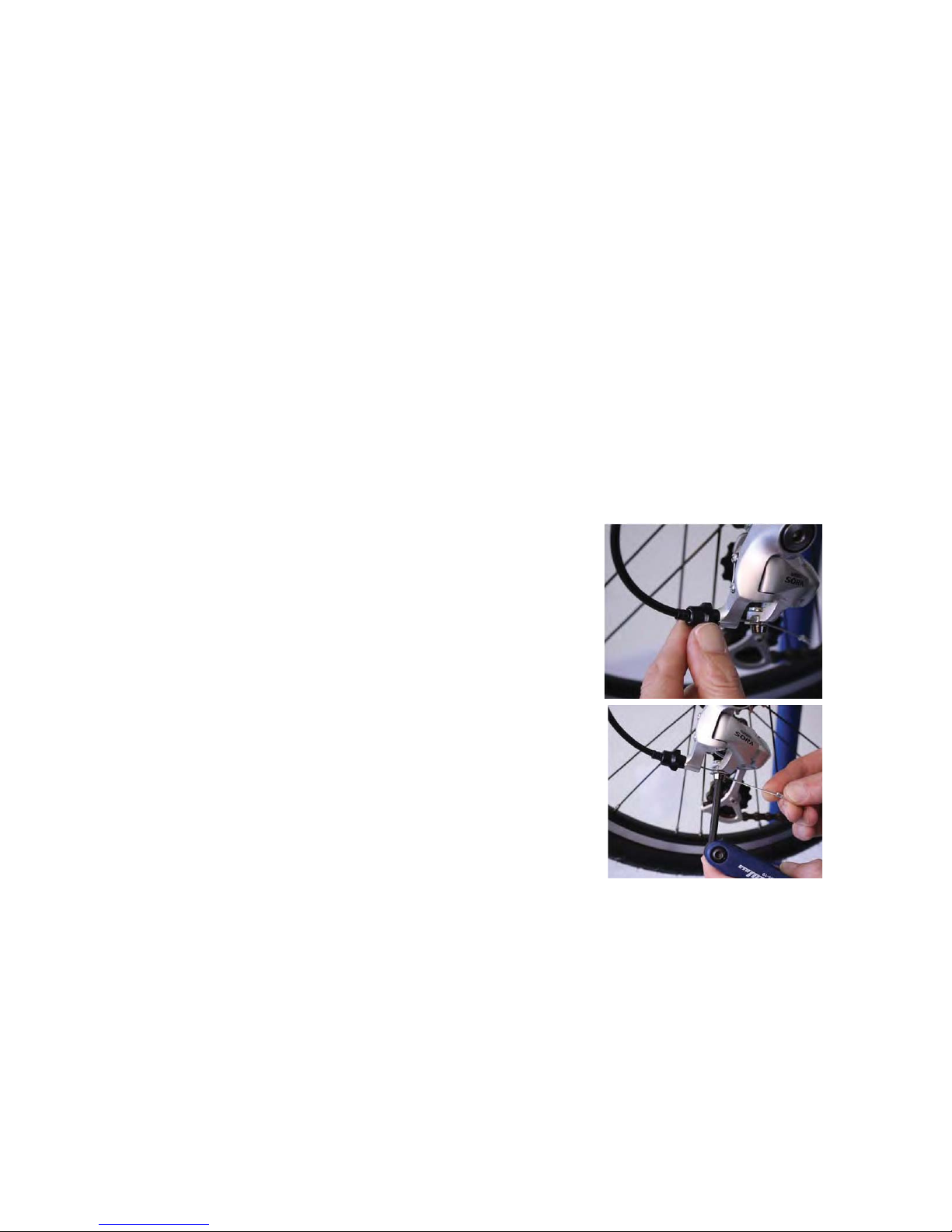
If the gears are not shifting smoothly, the cable tension
needs to be increased by turning the derailleur barrel adjustor r the shifter barrel adjustor counterclockwise. If the
gears over-shift into the next highest gear, the cable tension
needs to be decreased by turning one or both of the barrel adjustors clockwise. If these adjustments do not provide
enough of the needed change, you may adjust the cable
tension by loosening the Smm adjustor at the bottom of
the Shimano Sora derailleur. Move the cable in or out and
tighten the screw again.
Lubricate your chain on a regular basis.
21
Page 22
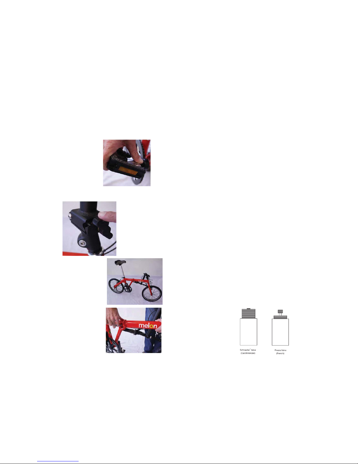
Follow these instructions for the proper folding of the
Melon Slice bicycle.
Folding Instructions
1. Fold up two pedals.
2. Unscrew the stem joint swivel. Twirl it around with one
fi nger-it works the fastest.
3. Fold the handlebars down
alongside the front tire. Be careful not to catch the cables in the
brake lever.
4. Lift the folding latch, swing it
out, and lift it up. You will hear a
click when it realeses.
22
Tire Valves
Bicycles primarily use either Schraeder™ or Presta tire
valves. To infl ate tires the pump needs to be fi tted with the
appropriate attachment specifi c to the valve stem.
The Schraeder™ valve is the most commonly used tire
valve. It is also known as the car or the American valve. Tires
fi tted with Schraeder™ valves can be infl ated using either a
hand pump or a service station pump, as it is the same valve
used on cars. Infl ation involves removing the valve dust cap,
then screwing or pushing on the pump connector o the end
of the valve stem and infl ating. By depressing the pin in the
end of the valve stem the tire can be defl ated.
The Presta valve is also referred to as the French or high
pressure valve. In order to infl ate tires equipped with this
valve, the pump needs to have a special fi tting attached
to accommodate the valve’s narrower profi le. The service
station pump can be used if an adapter is screwed onto the
valve stem. Infl ation involves removing the dust cap, unscrewing the valve stem locknut, freeing the valve stem by
pushing down on it, then fi tting the pump head and infl ating. Defl ation is achieved by opening the valve stem locknut
and depressing the valve stem.
Note: The valve dust cap should always be replaced in order to prevent dirt entering and damaging the valve.
Using a service station pump to infl ate tires is not encouraged as tires may blow out if sudden over infl ation occurs.
39
Page 23
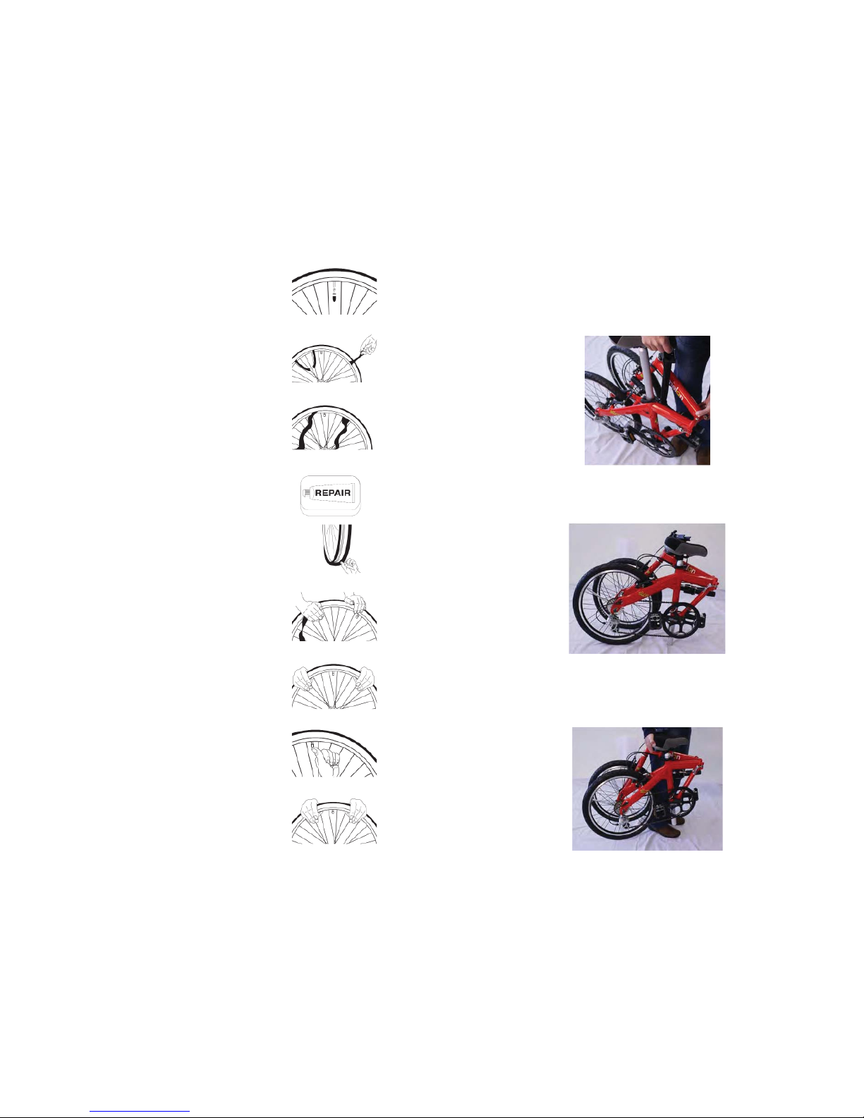
How To Repair A Flat Tire (cont’d)
1. Partially infl ate the tube with a
hand pump until it starts to take
shape.
2. Taking care not to twist the valve
stem, place it through the hole in
the rim and work the tube into the
tire.
3. Starting either side of the valve use
your hands to remount the other
side of the tire by pushing the
edge toward the centre of the rim.
Work around the rim until the tire is
almost completely remounted.
4. Push the valve up into the rim and
ensure that the tire sits properly in
position.
5. Remount the remainder of the tire
by using your thumbs to roll the
last, most diffi cult, part on.
6. Note: Do not use tire levers as
these can easily puncture the tube
or damage the tire.
7. Ensure that the tube is completely
free of the rim and the tire bead at
all points.
8. Infl ate the tube with a hand pump
until the tire begins to take shape,
ensuring the tire bead sits evenly
around the entire rim. Fully infl ate
the tire to the pressure marked on
the sidewall when properly positioned. Check pressure with a tire
air pressure gauge.
9. Replace the wheel into the frame
and adjust gears, brakes and quick
release levers as necessary.
38
5. Guide the handlebars through the frame as you fold the
bike in half.
6. Lower the seat post all the way down so that the saddle
is at its lowest point. Use the bottom of the seat post as a
support foot for the slice when in the folded position.
7. Carry the folded slice with the saddle on the opposite
side of the bike from your body. The saddle makes for a
great handle. You may also purchase a carrying bag available separately.
23
Page 24
WARNING:
Proper assembly and maintenance of your bicycle is your responsibility. Riding a bicycle that is
improperly assembled or maintained can result in
serious injury or even death.
CAUTIONS
Riding with an improperly tightened wheel can allow the
wheel to disengage from the bicycle.
An improperly tightened handle bar clamp may compromise the steering action of your bicycle. After making adjustments, always put the front wheel of the bike between
your legs and attempt to twist the handlebar/ stem assembly before riding. This action ensures everything has been
properly tightened.
Improperly tightened pedals can work loose and even fall
off.
Riding with an improperly tightened seat post can allow the
saddle to turn or move dramatically.
Do not fail to install the refl ectors on your bicycle. They are
an important part of your bike's safety system.
Like any mechanical device, a bicycle and its components
are subject to wear and stress. Component's have life
cycles. Please check your bicycle and its components on a
regular basis for signs of wear or damage. Product life is
often related to the type of riding that you do and to the
way that you treat your bicycle. Please take care of your
bicycle and use your good judgment in riding.
Please consider the following:
24
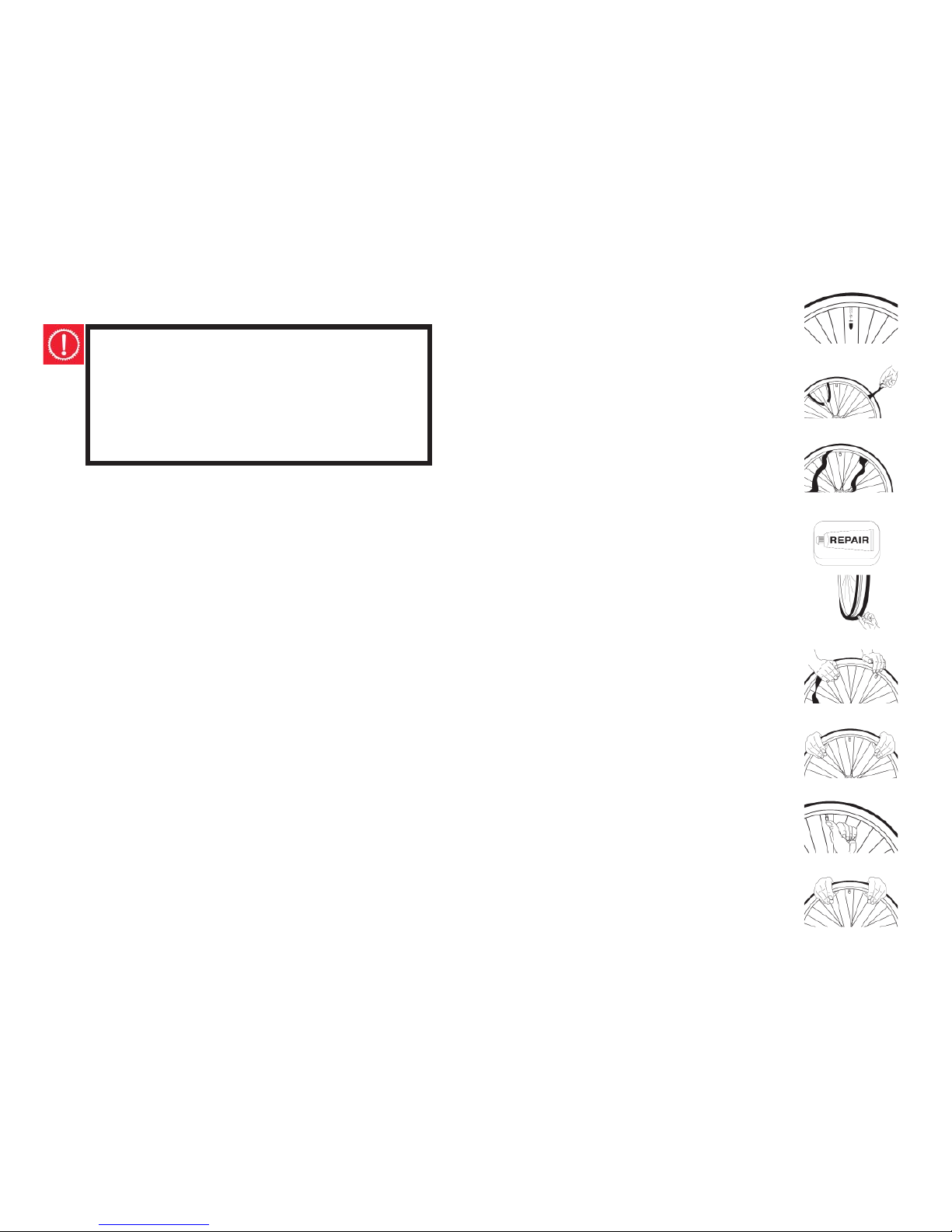
How To Repair A Flat Tire
There comes a time when most cyclists
will need to repair a fl at tire. Use the following steps to guide you through the
process:
1. Take the wheel off the bicycle.
2. Using the valve, entirely defl ate the
tire.
3. Push the tire bead inwards around the
whole rim to loosen.
4. Using tire levers only (to avoid damaging the rim), prise one side of the tire
bead up over the edge of the rim.
5. Leave the tire on the rim and remove
the tube.
6. Replace or repair the tube. Note: The
replacement tube size needs to correspond with the size detailed on the
sidewall of the tire and the valve type
needs to be suitable for your bicycle.
Refer to the instructions in your tire
repair kit to successfully patch a tube.
7. To determine the possible cause of
the leak, match the position of the
puncture in the tube in relation to the
tire and mark the location on the tire.
8. Remove the tire completely from the
rim and examine, removing any foreign objects noted, eg. glass or a nail.
Also inspect the inside of the rim for
other potential causes, such as protruding spokes. Replace the rim tape
covering the spoke ends, if damaged.
9. Remount the side of the tire onto the
rim.
37
Page 25

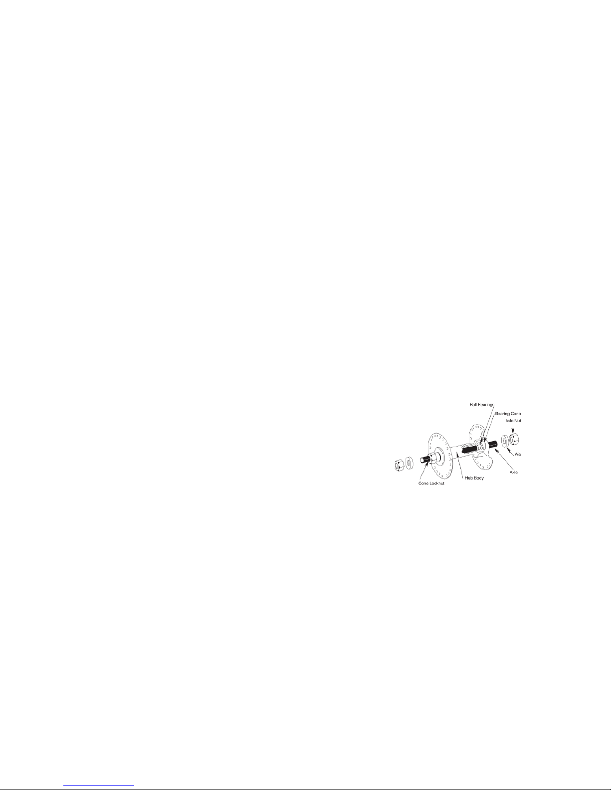
Hub Lubrication
At least once a year your wheel bearings need to be disassembled and re-greased. Riding in very muddy or wet
conditions will mean more frequent servicing. Due to the
complexity of the task you may prefer to have a professional bicycle mechanic perform the disassembly. However,
if you feel capable the process is listed below:
1. Take the wheel out of the frame.
2. Remove the axle nut, cone lock nut, and the bearing
cone from one side of the hub axle.
3. Remove the axle, complete with the cone and lock nut,
from the other side of the hub.
4. If your bicycle is fi tted with dust caps, carefully remove
them from both sides of the hub to expose the ball
bearings.
5. If ball bearings and ball retainers are present, carefully
remove these from both sides of the hub.
6. Remove the freewheel on rear hubs with screw on type
freewheels before disassembling the axle. (You will need
to use a special tool to do this.)
7. Clean all the hub components thoroughly and check
for damage, especially looking for pits or grazes in the
bearing surfaces and cones, and damaged ball bearings.
Replace if required.
8. Insert grease into each clean or new ball bearing and
into the inner cups of the hub, and refi t.
9. Re-assemble the hub axle in reverse sequence to disassembling, taking care to properly re-adjust the bearing
cones.
36
BICYCLE CARE
BASIC MAINTENANCE
To keep your bicycle in prime condition follow the recommendations below:
Painted frames should be dusted and any loose dirt dislodged with a dry cloth. Clean by wiping with a damp cloth
soaked in a mild detergent mixture. Use a cloth to dry
and polish with car or furniture wax. Plastic parts and rubber tires should be cleaned with soap and water. Wipe a
rust preventative fl uid over chrome plated bikes. All moving parts should be habitually cleaned and lubricated, and
components secured and adjusted as needed. Apply touch
up paint or clear nail varnish to any areas where the paint
has become scratched or clipped to the metal. This will help
prevent rusting. The potential for rusting is limited by the
use of alloy components and B.E.D (black electronic deposit) treated steel rims.
To avoid rapid bearing deterioration the hub and bottom
bracket bearings need to be removed and re-greased if
the bicycle has been submerged in water. Avoid cycling in
the rain or exposure to corrosive materials, such as the salt
from riding on the beach, as much as possible. If unavoidable, wash and dry your bicycle often and wipe or spray all
unpainted parts with an anti-rust treatment. Dry the wheel
rims so braking performance is not hindered.
25
Page 26
Storage
Protect your bicycle from the elements by storing it in a dry,
shady location. Prolonged ultra violet light exposure may
cause the paint to fade or the rubber and plastic parts to
crack. The bicycle should be cleaned, lubricated and the
frame waxed if it is to be stored for any length of time. Defl ate the tires to half pressure and hang the bicycle off the
ground. Store away from electric motors as ozone emissions
may damage the rubber and paint. Do not cover with plastic as rusting may occur due to “sweating.”
Security
In an attempt to prevent your bicycle from being stolen the
following precautions should be undertaken.
1. Take note of the bicycle serial number, generally located
underneath the bottom bracket of the frame.
2. Register the bicycle with the manufacturer/distributor
and local police
3. If your bicycle is left unattended, always secure it to an
immovable object, such as a lamp post. Use a high quality bicycle lock that will resist hack saws and bolt cutters.
Regular and proper upkeep of your new bike means:
• Smooth Running
• Longer lasting components
• Safer Riding
• Cost savings
•
Routine bicycle maintenance is an essential component of
riding. The condition of your bicycle changes every time
it is used, meaning more frequent maintenance is necessary the more you ride your bicycle. The tables listed below
outline the recommendations for servicing your bicycle. By
referring to these you should be able to complete most of
your bicycle maintenance yourself. Contact your specialist
bicycle dealer if you require further assistance.
26
Hub Bearing Adjustment
The hub bearings of both wheels should be inspected for
side movement. Adjustment is required if there is any more
than slight lateral movement.
To adjust:
1. Remove the wheel from the bicycle.
2. Use a fl at, open ended cone spanner to hold the adjusting cone of the hub and simultaneously loosen the hub’s
locknut on the same side.
3. Turn the adjusting cone as required until there is minimal
side play, and before binding of the bearings occurs.
4. Hold the adjusting cone in position and secure the locknut.
5. Test that the wheel spins freely without excessive lateral
movement, or binding on the bearings.
35
Page 27
Rear Wheel Replacement
1. Wheel replacement virtually follows the reverse process
to rear wheel removal
2. Hold the rear derailleur spring fully back and feed the
top part of the smallest hub cog into the top part of the
chain. Fit the wheel into the frame.
3. Ensure the wheel is centered correctly in the frame and
then fi rmly secure both axles nuts. To test if the wheel is
centered, inspect the distance between the front of the
wheel and the frame chainstay tubes on either side.
4. Reset the brake quick release and check the brake pad
clearance. If required, adjust the brake cable/pad clearance.
Caution:
Take care to correctly refi t a rear wheel. Failure
to do so may be dangerous.
Rear Wheel Removal
1. Open the brake quick release. Undo the brake cable
anchor bolt if greater clearance is required.
2. Move the chain onto the smallest rear cog.
3. When the wheel is fi tted with standard axle nuts, loosen
them with a 15mm wrench.
4. Hold the derailleur unit and allow the wheel to slide forward out of the frame.
5. Rest the bike upside down on the handlebars and saddle. After wheel is removed, do not rest bike on rear derailleur, as it may be damaged or misaligned as a result.
34
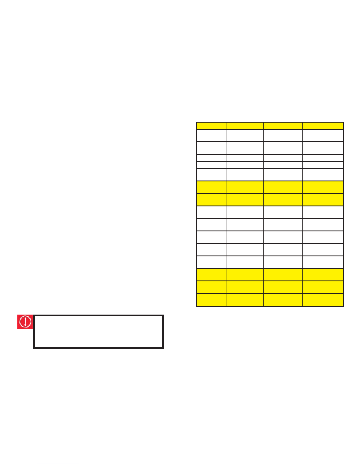
Frequency Component Lubricate How to Lubricate
Weekly Chain chain lube or
light oil
brush on or squirt
Derailleur
wheels
lube or light oil brush on or squirt
Derailleurs oil oil can
Brake callipers oil drops from oil can
Brake levers oil 2 drops from oil
can
Monthly Shift levers lithium based
grease
disassemble
Brake cable
ends
oil 1 drop from oil
can
Bi-Annual Hubs lithium based
grease
disassemble
Bottom bracket lithium based
grease
disassemble
Pedals lithium based
grease
disassemble
Brake cables lithium based
grease
disassemble
Derailleur
cables
lithium based
grease
disassemble
Yearly Wheels bear-
ings
lithium based
grease
disassemble
Headset lithium based
grease
disassemble
Seat pillar lithium based
grease
disassemble
Schedule 1 - Lubrication
Note: Increase the regularity of maintenance the more you
ride and use in wet or dusty conditions.
Take care not to over lubricate – excess lubricant should be
removed to prohibit dirt build up.
27
Page 28
WARNING:
Always seek expert advice for any maintenance
requirements you feel unable to complete. You
run the risk of potentially damaging your bicycle
or yourself from falling if your bike is not correctly
serviced or adjusted.
WARNING:
All components of the bicycle are subjected to
wear and stress through use. Watch closely for any
scratches, cracks or discoloration on your bicycle
components. These are signs of a stress-caused
fatigue and indicate that a part needs to be replaced. Failure to replace can cause the component to suddenly fail when riding, which may result
in serious injury or even death.
28
Front Wheel Removal
1. Open the brake quick release. You may need to undo
the brake cable anchor bolt if more clearance is required.
2. Use a 15mm wrench to loosen both axle nuts.
3. Remove the wheel.
Front Wheel Replacement
1. Guide the wheel into the frame ensuring that the axle
fi ts well up against the fork slots. The fork
2. legs may need to be slightly prised apart.
3. Firmly fasten both axle nuts.
4. Re-set the brake quick-release and inspect the brake
pad clearance. If able, adjust the brake cable/pad clearance.
33
Page 29
Recommended Tire Pressures:
Tire pressure directly infl uences the performance of a tire
on different surfaces and in varying weather conditions.
Recommended tire pressure is given either as maximum
pressure or as a pressure range.
For riding on smooth, slick terrain such as hard-packed clay
and on deep, loose surfaces such as deep, dry sand, tires
should be infl ated to lower pressures, at the bottom of the
recommended pressure range. This helps to cushion the
rider against the impact.
Using high pressures, at the top of the recommended pressure range enables a faster but rougher ride. These pressures are ideal for riding on a smooth, dry pavement.
Failure to suffi ciently infl ate the tires according to the rider’s
weight and intended use can cause the tube to puncture.
Tires should be infl ated to the recommended pressure
molded on the sidewall of the bicycle’s tires.
Caution:
Service station pumps and pencil type automotive
tire gauges should not be relied upon for consistent, accurate readings. A good quality dial gauge
should be used as it is far more accurate and reliable.
32
Frequency
Task
Before every ride Check tire pressure
Check brake operation
Check wheels for loose spokes
Make sure nothing is loose
After every ride Quick wipe down with damp cloth
Weekly Lubrication as per schedule
Monthly Lubrication as per schedule
Check derailleur adjustment
Check brake adjustment
Check brake and gear cable adjustment
Check tire wear and pressure
Check wheels are true and spokes tight
Check hub,head set and crank bearing for
looseness
Check pedals are tight
Check handlebars are tight
Check seat and seat posts are tight and
compfortablly adjusted
Check all nuts and bolts are tight
Bi-annual Lubrication as per schedule
Check all points as per monthly service
Check and replace brake pads if required
Check chain for excessive play or wear
Yearly Lubrication as per schedule
Schedule 2 - Service Checklist
29
Page 30

Axle nuts: Caution: Do not ride the bicycle without fi rst
ensuring that the axle nuts are tight.
Broken or loose spokes: Caution: Damaged spokes can
create severe instability and have the potential to cause an
accident for the rider. Before riding ensure that all spokes
are present, intact and are taut. Spoke repairs can be diffi cult and are best undertaken by a professional bicycle
mechanic.
Loose hub bearings: Caution: Do not ride your bicycle if
the hub bearings are loose or damaged. Check the hubs by
moving the wheel from side to side. If movement is detected adjustments will be needed.
Rims: Brakes can become ineffective if dirt or grease accumulate on the rims. Check that your rims are clean and
dry before using. Take care to prevent oil contact on the rim
braking surfaces when lubricating your bicycle.
Wheels Inspection
Maintaining your wheels in prime condition is imperative
for not only for riding effi ciency and performance, but
safety as well. When inspecting your wheels look for the
potential hazards listed below.
WHEELS AND TIRES
30
Tire inspection
As tires are the rider’s only contact with the road, correct
tire maintenance is crucial for stability and safety. Consider
the following when inspecting your tires:
Tread: Check the tread for signs of excessive wear or fl at
spots, and cuts or damage.
Caution: Riding on excessively worn or damaged tires
may be hazardous so tires should be replaced.
Infl ation: Maintain tire pressure at the level recommended
on the tire sidewalls. Preferably use a tire gauge and a
hand pump to infl ate rather than a service station pump.
Caution: Using a service station pump for infl ation can
lead to sudden over infl ation, potentially resulting in a
blow out.
Valves: A fl at tire is not only inconvenient but potentially
dangerous. To minimize the likelihood of a fl at tire from air
leaking from a valve, ensure valve caps are fi tted and that
valves are clean.
Bead setting: Ensure the bead is correctly fi tted in the rim
when infl ating or changing tires.
31
 Loading...