

Page 1

SwitchX 36-Port QSFP 40Gb/s Ethernet System
Hardware User Manual
P/N:MSX10XX
Rev 1.3
www.mellanox.com
Page 2

Rev 1.3
Mellanox Technologies
350 Oakmead Parkway Suite 100
Sunnyvale, CA 94085
U.S.A.
www.mellanox.com
Tel: (408) 970-3400
Fax: (408) 970-3403
Mellanox Technologies, Ltd.
Beit Mellanox
PO Box 586 Yokneam 20692
Israel
www.mellanox.com
Tel: +972 (0)74 723 7200
Fax: +972 (0)4 959 3245
Mellanox®, Mellanox logo, BridgeX®, ConnectX®, CORE-Direct®, InfiniBridge®, InfiniHost®, InfiniScale®, PhyX®,
SwitchX®, Virtual Protocol Interconnect® and Voltaire® are registered trademarks of Mellanox Technologies, Ltd.
Connect-IB™, FabricIT™, MLNX-OS™, ScalableHPC™, Unbreakable-Link™, UFM™ and Unified Fabric Manager™ are
trademarks of Mellanox Technologies, Ltd. All other trademarks are property of their respective owners.
© Copyright 2012. Mellanox Technologies. All Rights Reserved.
NOTE:
THIS HARDWARE, SOFTWARE OR TEST SUITE PRODUCT (“PRODUCT(S)”) AND ITS RELATED
DOCUMENTATION ARE PROVIDED BY MELLANOX TECHNOLOGIES “AS-IS” WITH ALL FAULTS OF ANY
KIND AND SOLELY FOR THE PURPOSE OF AIDING THE CUSTOMER IN TESTING APPLICATIONS THAT USE
THE PRODUCTS IN DESIGNATED SOLUTIONS. THE CUSTOMER'S MANUFACTURING TEST ENVIRONMENT
HAS NOT MET THE STANDARDS SET BY MELLANOX TECHNOLOGIES TO FULLY QUALIFY THE
PRODUCTO(S) AND/OR THE SYSTEM USING IT. THEREFORE, MELLANOX TECHNOLOGIES CANNOT AND
DOES NOT GUARANTEE OR WARRANT THAT THE PRODUCTS WILL OPERATE WITH THE HIGHEST
QUALITY. ANY EXPRESS OR IMPLIED WARRANTIES, INCLUDING, BUT NOT LIMITED TO, THE IMPLIED
WARRANTIES OF MERCHANTABILITY, FITNESS FOR A PARTICULAR PURPOSE AND NONINFRINGEMENT
ARE DISCLAIMED. IN NO EVENT SHALL MELLANOX BE LIABLE TO CUSTOMER OR ANY THIRD PARTIES
FOR ANY DIRECT, INDIRECT, SPECIAL, EXEMPLARY, OR CONSEQUENTIAL DAMAGES OF ANY KIND
(INCLUDING, BUT NOT LIMITED TO, PAYMENT FOR PROCUREMENT OF SUBSTITUTE GOODS OR SERVICES;
LOSS OF USE, DATA, OR PROFITS; OR BUSINESS INTERRUPTION) HOWEVER CAUSED AND ON ANY
THEORY OF LIABILITY, WHETHER IN CONTRACT, STRICT LIABILITY, OR TORT (INCLUDING NEGLIGENCE
OR OTHERWISE) ARISING IN ANY WAY FROM THE USE OF THE PRODUCT(S) AND RELATED
DOCUMENTATION EVEN IF ADVISED OF THE POSSIBILITY OF SUCH DAMAGE.
2
Mellanox Technologies
Document Number: 3459
Page 3

SwitchX 36-Port QSFP 40Gb/s Ethernet System Hardware User Manual Rev 1.3
Table of Contents
List of Figures . . . . . . . . . . . . . . . . . . . . . . . . . . . . . . . . . . . . . . . . . . . . . . . . . . . . . . . . . . . . . . . . . . . .5
List of Tables . . . . . . . . . . . . . . . . . . . . . . . . . . . . . . . . . . . . . . . . . . . . . . . . . . . . . . . . . . . . . . . . . . . . .7
Revision History . . . . . . . . . . . . . . . . . . . . . . . . . . . . . . . . . . . . . . . . . . . . . . . . . . . . . . . . . . . . . . . . . .8
About this Manual . . . . . . . . . . . . . . . . . . . . . . . . . . . . . . . . . . . . . . . . . . . . . . . . . . . . . . . . . . . . . . . .9
Intended Audience . . . . . . . . . . . . . . . . . . . . . . . . . . . . . . . . . . . . . . . . . . . . . . . . . . . . . . . . . . . . . . . . . 9
Related Documentation . . . . . . . . . . . . . . . . . . . . . . . . . . . . . . . . . . . . . . . . . . . . . . . . . . . . . . . . . . . . . . 9
Conventions . . . . . . . . . . . . . . . . . . . . . . . . . . . . . . . . . . . . . . . . . . . . . . . . . . . . . . . . . . . . . . . . . . . . . . 9
Abreviations . . . . . . . . . . . . . . . . . . . . . . . . . . . . . . . . . . . . . . . . . . . . . . . . . . . . . . . . . . . . . . . . . . . . . 10
Mellanox Part Numbering Legend . . . . . . . . . . . . . . . . . . . . . . . . . . . . . . . . . . . . . . . . . . . . . . . . . . . 10
Chapter 1 Overview . . . . . . . . . . . . . . . . . . . . . . . . . . . . . . . . . . . . . . . . . . . . . . . . . . . . . . . . . 11
1.1 Features- - - - - - - - - - - - - - - - - - - - - - - - - - - - - - - - - - - - - - - - - - - - - - - - - - - - - - - - - - - - 12
1.1.1 Full Feature List . . . . . . . . . . . . . . . . . . . . . . . . . . . . . . . . . . . . . . . . . . . . . . . . . . . . . . . . . . 12
1.2 Serial Number and Product Version Information - - - - - - - - - - - - - - - - - - - - - - - - - - - - - - - - 12
Chapter 2 40 Gb/s Ethernet . . . . . . . . . . . . . . . . . . . . . . . . . . . . . . . . . . . . . . . . . . . . . . . . . . . 14
Chapter 3 Basic Operation and Installation. . . . . . . . . . . . . . . . . . . . . . . . . . . . . . . . . . . . . . 15
3.1 Switch Platform Hardware Overview - - - - - - - - - - - - - - - - - - - - - - - - - - - - - - - - - - - - - - - - 15
3.1.1 Status LEDs . . . . . . . . . . . . . . . . . . . . . . . . . . . . . . . . . . . . . . . . . . . . . . . . . . . . . . . . . . . . . 15
3.1.2 Reset Button . . . . . . . . . . . . . . . . . . . . . . . . . . . . . . . . . . . . . . . . . . . . . . . . . . . . . . . . . . . . . 20
3.2 Air Flow - - - - - - - - - - - - - - - - - - - - - - - - - - - - - - - - - - - - - - - - - - - - - - - - - - - - - - - - - - - 22
3.3 QSFP Cable Power Budget Classification - - - - - - - - - - - - - - - - - - - - - - - - - - - - - - - - - - - - - 22
3.4 Interfaces - - - - - - - - - - - - - - - - - - - - - - - - - - - - - - - - - - - - - - - - - - - - - - - - - - - - - - - - - - - 23
3.4.1 Port Connector Interfaces. . . . . . . . . . . . . . . . . . . . . . . . . . . . . . . . . . . . . . . . . . . . . . . . . . . 23
3.4.2 Management and Firmware Updating Interfaces . . . . . . . . . . . . . . . . . . . . . . . . . . . . . . . . . 23
3.5 Switch Platform Installation and Operation - - - - - - - - - - - - - - - - - - - - - - - - - - - - - - - - - - - - 24
3.5.1 Installation Safety Warnings. . . . . . . . . . . . . . . . . . . . . . . . . . . . . . . . . . . . . . . . . . . . . . . . . 25
3.5.2 Mechanical Installation. . . . . . . . . . . . . . . . . . . . . . . . . . . . . . . . . . . . . . . . . . . . . . . . . . . . . 27
3.6 Package Contents and Installation - - - - - - - - - - - - - - - - - - - - - - - - - - - - - - - - - - - - - - - - - - 28
3.6.1 Installing the Switch in the Rack . . . . . . . . . . . . . . . . . . . . . . . . . . . . . . . . . . . . . . . . . . . . . 28
3.7 Grounding the Switch - - - - - - - - - - - - - - - - - - - - - - - - - - - - - - - - - - - - - - - - - - - - - - - - - - 33
3.8 Power Connections and Initial Power On - - - - - - - - - - - - - - - - - - - - - - - - - - - - - - - - - - - - - 33
3.9 Extracting and Inserting the Power Supply Unit - - - - - - - - - - - - - - - - - - - - - - - - - - - - - - - - - 35
3.10 Supported Approved Cables - - - - - - - - - - - - - - - - - - - - - - - - - - - - - - - - - - - - - - - - - - - - - 36
3.11 Splitting the Data Stream Using Breakout (Fanout) Cables- - - - - - - - - - - - - - - - - - - - - - - - - 36
3.12 Cable Installation- - - - - - - - - - - - - - - - - - - - - - - - - - - - - - - - - - - - - - - - - - - - - - - - - - - - - 39
3.13 Extracting and Inserting the Fan Unit- - - - - - - - - - - - - - - - - - - - - - - - - - - - - - - - - - - - - - - 40
3.14 Switch Shut Down Procedure - - - - - - - - - - - - - - - - - - - - - - - - - - - - - - - - - - - - - - - - - - - - 41
3.15 Disassembly of the Switch from the Rack - - - - - - - - - - - - - - - - - - - - - - - - - - - - - - - - - - - - 42
3.16 Disposal - - - - - - - - - - - - - - - - - - - - - - - - - - - - - - - - - - - - - - - - - - - - - - - - - - - - - - - - - - 42
3.17 Resetting the Switch- - - - - - - - - - - - - - - - - - - - - - - - - - - - - - - - - - - - - - - - - - - - - - - - - - - 42
Chapter 4 Management and Tools Overview. . . . . . . . . . . . . . . . . . . . . . . . . . . . . . . . . . . . . 44
4.1 Chassis Management Using the MLNX-OS™ Software - - - - - - - - - - - - - - - - - - - - - - - - - - - 44
4.2 Configuring the Switch for the First Time - - - - - - - - - - - - - - - - - - - - - - - - - - - - - - - - - - - - 44
4.2.1 Starting a Remote Connection to the Switch . . . . . . . . . . . . . . . . . . . . . . . . . . . . . . . . . . . . 45
4.2.2 Upgrading Software . . . . . . . . . . . . . . . . . . . . . . . . . . . . . . . . . . . . . . . . . . . . . . . . . . . . . . . 45
Chapter 5 Troubleshooting . . . . . . . . . . . . . . . . . . . . . . . . . . . . . . . . . . . . . . . . . . . . . . . . . . . 46
Appendix A Specification. . . . . . . . . . . . . . . . . . . . . . . . . . . . . . . . . . . . . . . . . . . . . . . . . . . . . . . 49
A.1 Approved Cables . . . . . . . . . . . . . . . . . . . . . . . . . . . . . . . . . . . . . . . . . . . . . . . . . . . . . . . . . . . . . 51
A.2 EMC Certifications . . . . . . . . . . . . . . . . . . . . . . . . . . . . . . . . . . . . . . . . . . . . . . . . . . . . . . . . . . . . 51
A.3 China CCC Warning Statement . . . . . . . . . . . . . . . . . . . . . . . . . . . . . . . . . . . . . . . . . . . . . . . . . . 52
Mellanox Technologies
3
Page 4

Rev 1.3
Appendix B Transferring the Power Cord . . . . . . . . . . . . . . . . . . . . . . . . . . . . . . . . . . . . . . . . 54
Appendix C QSFP Interface . . . . . . . . . . . . . . . . . . . . . . . . . . . . . . . . . . . . . . . . . . . . . . . . . . . . 56
Appendix D RJ-45 CONSOLE and Ethernet interfaces . . . . . . . . . . . . . . . . . . . . . . . . . . . . . .58
Appendix E Replacement Parts Ordering Numbers. . . . . . . . . . . . . . . . . . . . . . . . . . . . . . . . . 59
Appendix F Avertissements de sécurité d’installation (French) . . . . . . . . . . . . . . . . . . . . . . . 60
Appendix G Installation - Sicherheitshinweise (German) . . . . . . . . . . . . . . . . . . . . . . . . . . . . .64
Appendix H Advertencias de seguridad para la instalación (Spanish) . . . . . . . . . . . . . . . . . . .68
4
Mellanox Technologies
Page 5

SwitchX 36-Port QSFP 40Gb/s Ethernet System Hardware User Manual Rev 1.3
List of Figures
Figure 1: Connector Side View of the Switch . . . . . . . . . . . . . . . . . . . . . . . . . . . . . . . . . . . . . . . .11
Figure 2: Pull Out Tab . . . . . . . . . . . . . . . . . . . . . . . . . . . . . . . . . . . . . . . . . . . . . . . . . . . . . . . . . . .13
Figure 3: QSFP Switch System Power and Connector Side Panels . . . . . . . . . . . . . . . . . . . . . . . .15
Figure 4: System Status Indicators . . . . . . . . . . . . . . . . . . . . . . . . . . . . . . . . . . . . . . . . . . . . . . . . .1 5
Figure 5: Power, Fan, and System LEDs . . . . . . . . . . . . . . . . . . . . . . . . . . . . . . . . . . . . . . . . . . . .17
Figure 6: Fan Status LED Connector Side . . . . . . . . . . . . . . . . . . . . . . . . . . . . . . . . . . . . . . . . . . .17
Figure 7: Fan Status LED Power side . . . . . . . . . . . . . . . . . . . . . . . . . . . . . . . . . . . . . . . . . . . . . . .18
Figure 8: Power Side Panel . . . . . . . . . . . . . . . . . . . . . . . . . . . . . . . . . . . . . . . . . . . . . . . . . . . . . . .19
Figure 9: PS Unit Status LEDs . . . . . . . . . . . . . . . . . . . . . . . . . . . . . . . . . . . . . . . . . . . . . . . . . . . .19
Figure 10: Bad Port LED . . . . . . . . . . . . . . . . . . . . . . . . . . . . . . . . . . . . . . . . . . . . . . . . . . . . . . . . .20
Figure 11: Reset Button . . . . . . . . . . . . . . . . . . . . . . . . . . . . . . . . . . . . . . . . . . . . . . . . . . . . . . . . . .21
Figure 12: Port LEDs . . . . . . . . . . . . . . . . . . . . . . . . . . . . . . . . . . . . . . . . . . . . . . . . . . . . . . . . . . . .21
Figure 13: Port Numbering . . . . . . . . . . . . . . . . . . . . . . . . . . . . . . . . . . . . . . . . . . . . . . . . . . . . . . . .23
Figure 14: Top and Bottom Port Orientation . . . . . . . . . . . . . . . . . . . . . . . . . . . . . . . . . . . . . . . . . .23
Figure 15: Management Interfaces . . . . . . . . . . . . . . . . . . . . . . . . . . . . . . . . . . . . . . . . . . . . . . . . . . .23
Figure 16: Rack Rail Kit Parts . . . . . . . . . . . . . . . . . . . . . . . . . . . . . . . . . . . . . . . . . . . . . . . . . . . . .29
Figure 17: Placement of Switch in Rack . . . . . . . . . . . . . . . . . . . . . . . . . . . . . . . . . . . . . . . . . . . . . .3 0
Figure 18: Mounting Options . . . . . . . . . . . . . . . . . . . . . . . . . . . . . . . . . . . . . . . . . . . . . . . . . . . . . .31
Figure 19: Screwing on the Rail . . . . . . . . . . . . . . . . . . . . . . . . . . . . . . . . . . . . . . . . . . . . . . . . . . . . .31
Figure 20: Inserting the Caged Nuts . . . . . . . . . . . . . . . . . . . . . . . . . . . . . . . . . . . . . . . . . . . . . . . . .32
Figure 21: Slide the Rail into the Rail Slide . . . . . . . . . . . . . . . . . . . . . . . . . . . . . . . . . . . . . . . . . . .32
Figure 22: Status LEDs 5 Minutes After Power On . . . . . . . . . . . . . . . . . . . . . . . . . . . . . . . . . . . . .33
Figure 23: Two Power Inlets - Electric Caution Notifications . . . . . . . . . . . . . . . . . . . . . . . . . . . . .34
Figure 24: Fan and PS unit Air Flow Direction . . . . . . . . . . . . . . . . . . . . . . . . . . . . . . . . . . . . . . . . .35
Figure 25: Power Supply Unit Extraction . . . . . . . . . . . . . . . . . . . . . . . . . . . . . . . . . . . . . . . . . . . . .35
Figure 26: PS Unit Pulled Out . . . . . . . . . . . . . . . . . . . . . . . . . . . . . . . . . . . . . . . . . . . . . . . . . . . . . .36
Figure 27: Breakout or Fanout Cable . . . . . . . . . . . . . . . . . . . . . . . . . . . . . . . . . . . . . . . . . . . . . . . . .37
Figure 28: Port Splitting Options . . . . . . . . . . . . . . . . . . . . . . . . . . . . . . . . . . . . . . . . . . . . . . . . . . . .37
Figure 29: 3 Examples of Port Mapping Assignment . . . . . . . . . . . . . . . . . . . . . . . . . . . . . . . . . . . .39
Figure 30: Top and Bottom Ports . . . . . . . . . . . . . . . . . . . . . . . . . . . . . . . . . . . . . . . . . . . . . . . . . . . .40
Figure 31: Air Flow Labels . . . . . . . . . . . . . . . . . . . . . . . . . . . . . . . . . . . . . . . . . . . . . . . . . . . . . . . .41
Figure 32: Fan Module Latches . . . . . . . . . . . . . . . . . . . . . . . . . . . . . . . . . . . . . . . . . . . . . . . . . . . . .41
Figure 33: Reset Button . . . . . . . . . . . . . . . . . . . . . . . . . . . . . . . . . . . . . . . . . . . . . . . . . . . . . . . . . .43
Figure 34: Host Connection . . . . . . . . . . . . . . . . . . . . . . . . . . . . . . . . . . . . . . . . . . . . . . . . . . . . . . .44
Figure 35: Transfer Power Cord . . . . . . . . . . . . . . . . . . . . . . . . . . . . . . . . . . . . . . . . . . . . . . . . . . . .54
Figure 36: Put the Cord Through the Switch Slide Before Screwing it to the Switch . . . . . . . . . . . .54
Mellanox Technologies
5
Page 6

Rev 1.3
Figure 37: Screw the Switch Slide to the Switch . . . . . . . . . . . . . . . . . . . . . . . . . . . . . . . . . . . . . . . .55
Figure 38: Transfer Power Cord Finished . . . . . . . . . . . . . . . . . . . . . . . . . . . . . . . . . . . . . . . . . . . . .55
Figure 39: QSFP Connector Male and Female Views . . . . . . . . . . . . . . . . . . . . . . . . . . . . . . . . . . . .57
6
Mellanox Technologies
Page 7

SwitchX 36-Port QSFP 40Gb/s Ethernet System Hardware User Manual Rev 1.3
List of Tables
Table 1: Revision History Table 8
Table 2: Reference Documents and Web Sites 9
Table 3: System Status LED Configurations 17
Table 4: Fan Status LED Configurations 18
Table 5: PS Unit Status LED Configurations 19
Table 6: Bad Port LED Configurations 20
Table 7: Port Connector Physical and Logical Link Indications for Ethernet 21
Table 8: Air Flow Direction 22
Table 9: Installation Kit According to Rack Size 27
Table 10: Port Splitting Options 38
Table 11: SX103[56]Specification Data 49
Table 12: InfiniBand QSFP Connector Pinout 56
Table 13: RJ-45 Pinout 58
Table 14: Replacement Parts Ordering Numbers 59
Mellanox Technologies
7
Page 8
Rev 1.3
Revision History
Table 1 - Revision History Table
Date Revision Description
October 2012 1.3 Added caution not to insert cables with excessive force.
September 2012 1.2 Added examples of Port mapping
Replaced Visio Graphics with Mechanical drawings.
Added Figure 17.
Added China CCC warning statement
February 2012 1.1 A dded one OPN
Added China RoHS to the parts list
Added Appendix for Thermal Threshold Definitions
Removed reference to spring clip in Appendix “Transferring the Power Cord”
Changed Specifications table formatting 4 column to 2 column
Fixed port LED assignment
Added Cable Splitting section
July 2011 1.0 Initial Release
8
Mellanox Technologies
Page 9
SwitchX 36-Port QSFP 40Gb/s Ethernet System Hardware User Manual Rev 1.3
About this Manual
This manual describes the installation and basic use of the Mellanox switch which is based on the
SwitchX switch device.
Intended Audience
This manual is intended for users and system administrators responsible for designing and testing switch platforms.
Related Documentation
Additional Documentation available from Mellanox:
Table 2 - Reference Documents and Web Sites
Document Name Description
Mellanox SwitchX® Switch Products
Release Notes
Mellanox MLNX-OS SwitchX Software User Manual
MLNX-OS Software Command Reference Guide
MLNX-OS Software Configuration
Guide
For possible hardware issues see the switch support product page. This
requires a customer support login.
This document contains information regarding configuring and managing Mellanox Technologies' SwitchX Switch Platforms.
Command Reference Guide for MLNX-OS listing all of the commands
available through MLNX-OS with explanations and examples.
Configuration Guide for MLNX-OS displaying different configuration
scenarios.
All of these documents can be found on the Mellanox Website. They are available either through
the product pages or through the support page with a login and password.
Conventions
Throughout this manual, the name SX10XX and the term switch are used to describe the 36-port
QSFP40Gb/s Ethernet switch, unless explicitly indicated otherwise.
The following icons are used throughout this document to indicate information that is important
to the user.
This icon makes recommendations to the user.
This icon indicates information that is helpful to the user.
Mellanox Technologies
9
Page 10
Rev 1.3
This icon indicates a situation that can potentially cause damage to hardware or software.
BEWARE! This icon indicates a situation that can potentially cause personal injury or
damage to hardware or software.
Abreviations
FDR — Fourteen Data Rate
Mellanox Part Numbering Legend
Place Field Decoder
M Mellanox Technologies
SX System Type SwitchX Switch
P Data Transfer Protocol 1 = Ethernet
R Size of box 0 = 1U
1 = 1.5U
2 = 2U
40 Gb/s equivalent
throughput
16 = 640Gb/s
24 = 960Gb/s
35 = 2880 Gb/s Light version of the Management software
36 = 2880 Gb/s
C Data Rate B = 40Gb/s Ethernet
- Separator
P # Power Supplies 0=0, 1=1, 2=2....
M Depth of the Unit S = standard depth, B = short depth
Y Air Flow direction R= Connector side to Power side airflow
F= Power Side side to Connector side airflow
R Chip Generation R – SwitchX
10
Mellanox Technologies
S – SwitchX-2
Page 11
SwitchX 36-Port QSFP 40Gb/s Ethernet System Hardware User Manual Rev 1.3
1 Overview
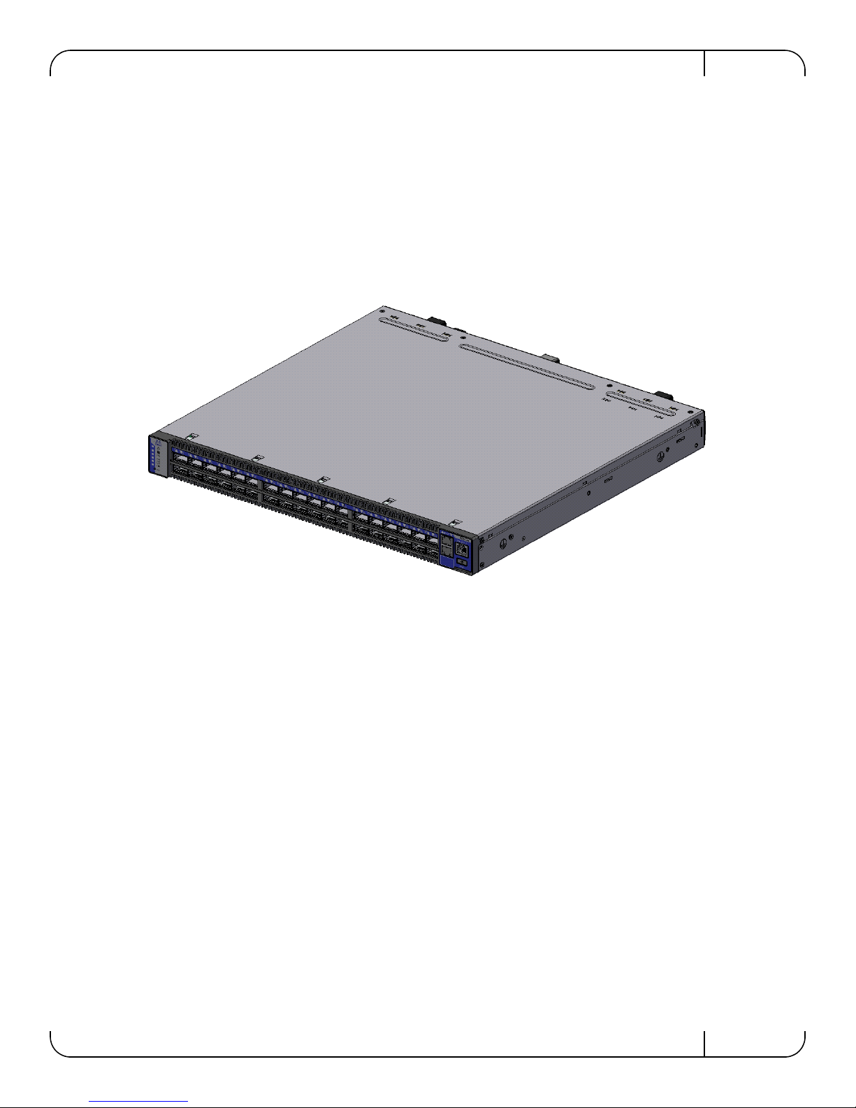
The SX10xx Ethernet system switch family prov ides the highest-performing fabric solution in a
1U form factor by delivering up to 2.88Tb/s of non-blocking throughput to High-Performance
Computing (HPC), high frequency trading and Enterprise Data Centers (EDC), with ultra-lowlatency. It has 36 40GbE ports that when connected to Mellanox NICs with Mellanox cables and
adapters gives you the optimal end-to-end solution for Ethernet Data-Centers.
Figure 1: Connector Side View of the Switch
Mellanox Technologies
11
Page 12

1.1 Features
1.1.1 Full Feature List
•DHCP
•Telnet
• SSHv2
•CLI
• FTP
• TFTP
•SCP
• Upload/download configuration
• Static MAC
•Syslog
OverviewRev 1.3
• System alarms
• Auto temperature control
• Simple Network Time Protocol SNTP
•RADIUS
•TACACS+
• LDAP
• 802.1w RSTP
• 802.3x Flow Control
• 802.1Qab PFC
•802.1Qaz - ETS
•Dual SW Image
• Familiar industry standard CLI
• Forward Error Correction (FEC) *
1.2 Serial Number and Product Version Information
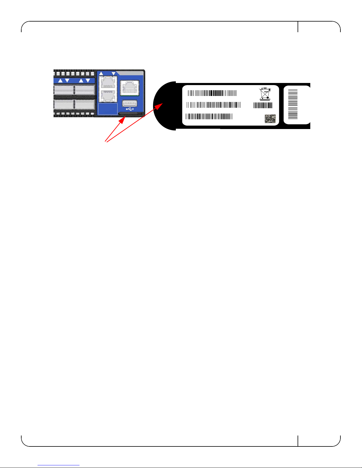
The Serial number and the MAC for the switch are found on the pull out tab below the USB connector. The MAC for the Management PC is also on this tab. This MAC is for the mgmt0 management interface (the top Ethernet port). The second interface mgmt1 has the next consecutive
MAC.
12
Mellanox Technologies
Page 13
SwitchX 36-Port QSFP 40Gb/s Ethernet System Hardware User Manual Rev 1.3
S/N: MT1117X00014
P/N: MSX1035B -1BFR
MA C: 0002C9020040
M a d e in IL
MGT :
00:02:C9:11:A2:01
Rev:A1
36
35
MGT
1
2
SX1035
CONSOLE
34
33
Pull out tab
Figure 2: Pull Out Tab
Mellanox Technologies
13
Page 14

2 40 Gb/s Ethernet
40 GbE is only guaranteed to work with approved Mellanox Cables.
Each QSFP port is capable of up to 40Gb/s as well as 10Gb/s with a QSA QSFP to SFP+ adaptor
or QSFP to SFP+ Mellanox cables. The switch contains 36 ports of 40GbE. Each port can be
connected with QSFP cables and connectors for 40Gb/s speed, or 10Gb/s speed when connecting
through QSA Mellanox adaptors.
Specific ports can support breakout cables. See “Splitting the Data Stream Using Breakout
(Fanout) Cables” on page 36 for mor information.
40 Gb/s EthernetRev 1. 3
14
Mellanox Technologies
Page 15
SwitchX 36-Port QSFP 40Gb/s Ethernet System Hardware User Manual Rev 1.3
OK
!
!
OK
OK
!
!
OK
12C
SX1036
Power Side Panel
Connector Side Panel
Power side
status LED
Connector side
status LED
Green – OK
Yellow – a fault in the system
Red – Major Fault or Fatal Error
LED color shows the
switch status
These three symbols show the
possible colors for the LED
below.
Both of these LEDs show the
switch status. One is on the
Power side and one is on the
Connector side
3 Basic Operation and Installation
3.1 Switch Platform Hardware Overview
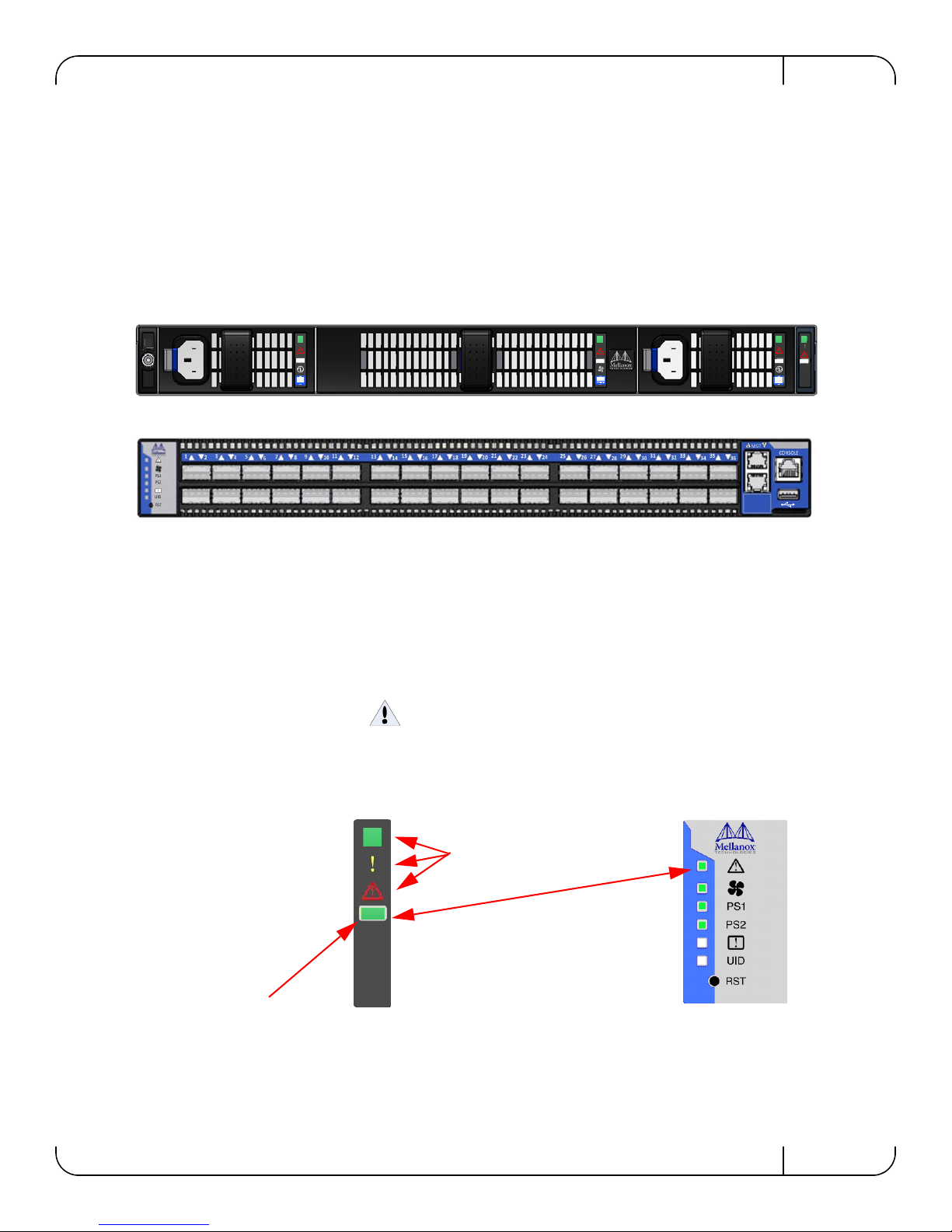
Figure 3 shows the power side panel and connector side panel views of the switch. The figure
shows port configurations for the switch systems, the hot-swap power supply location, the hotswap fan module, 2 – Ethernet RJ-45 connectors for management, 1 – RJ-45 connector for con
necting to a host PC, 1 – USB connector, and various status LEDs.
Figure 3: QSFP Switch System Power and Connector Side Panels
-
All connectivity except for power cords is via the connector side panel. All connectors can support active cables.
3.1.1 St atus LEDs
3.1.1.1 System Status Indicators
The System Status Indicators are located to the left of the connectors on the connector side panel,
and on the power side at the far right. Both of these LEDs give identical information.
Figure 4: System Status Indicators
Mellanox Technologies
15
Page 16
Basic Operation and InstallationRev 1.3
The system status indicators should display as follows:
• When the switch is plugged in, within five minutes the STATUS LED should light up
green.
• The PS1 LED for the plugged in PS unit should light up green
• The PS2 LED for the second PS unit should light up green only if a second PS unit is
installed in the switch for redundancy and Hot-Swap ability and it is connected to a
power source.
• If two PS units are installed and only one PS unit is connected to a power supply the PS2
LED will be red.
• If only one PS unit is installed in the switch, the PS2 LED will be off.
• The FAN LED should light up green.
As long as there is power to the switch (one PS unit is connected), and the switch is
booted up and running, the status LED should be green.
If the STATUS LED shows red after five minutes, unplug the switch and call your
Mellanox representative for assistance.
If the FAN LED shows red, troubleshoot the fan module. See “Troubleshooting” on page 46.
If the switch shuts down due to over temperature, unplug the switch, wait 5 minutes
and replug in the switch. For more information
See “Troubleshooting” on page 46.
If the PS LEDs are not green, this indicates a problem with the power supplies. The switch is
operational only if at least one of the PS LEDs is green.
16
Mellanox Technologies
Page 17
SwitchX 36-Port QSFP 40Gb/s Ethernet System Hardware User Manual Rev 1.3
!
PS1
PS2
!
UID
RST
1
2
RST
UID
PS2
PS1
This is a two color LED
Green — OK
Red — Major fault
Off — No power to the fans
Figure 5: Power , Fan, and System LEDs
Table 3 - System S tatus LED Configurations
LED Configuration STATUS/ System Health LED
Solid Green OK – The system is up and running.
Flashing Green The system is booting up. This assignment is valid on managed systems only.
Solid Red Major Error – Possible damage can result to the switch. Turn off immediately.
e.g. bad firmware, can’t boot, overheated
Off Off – The system has no power.
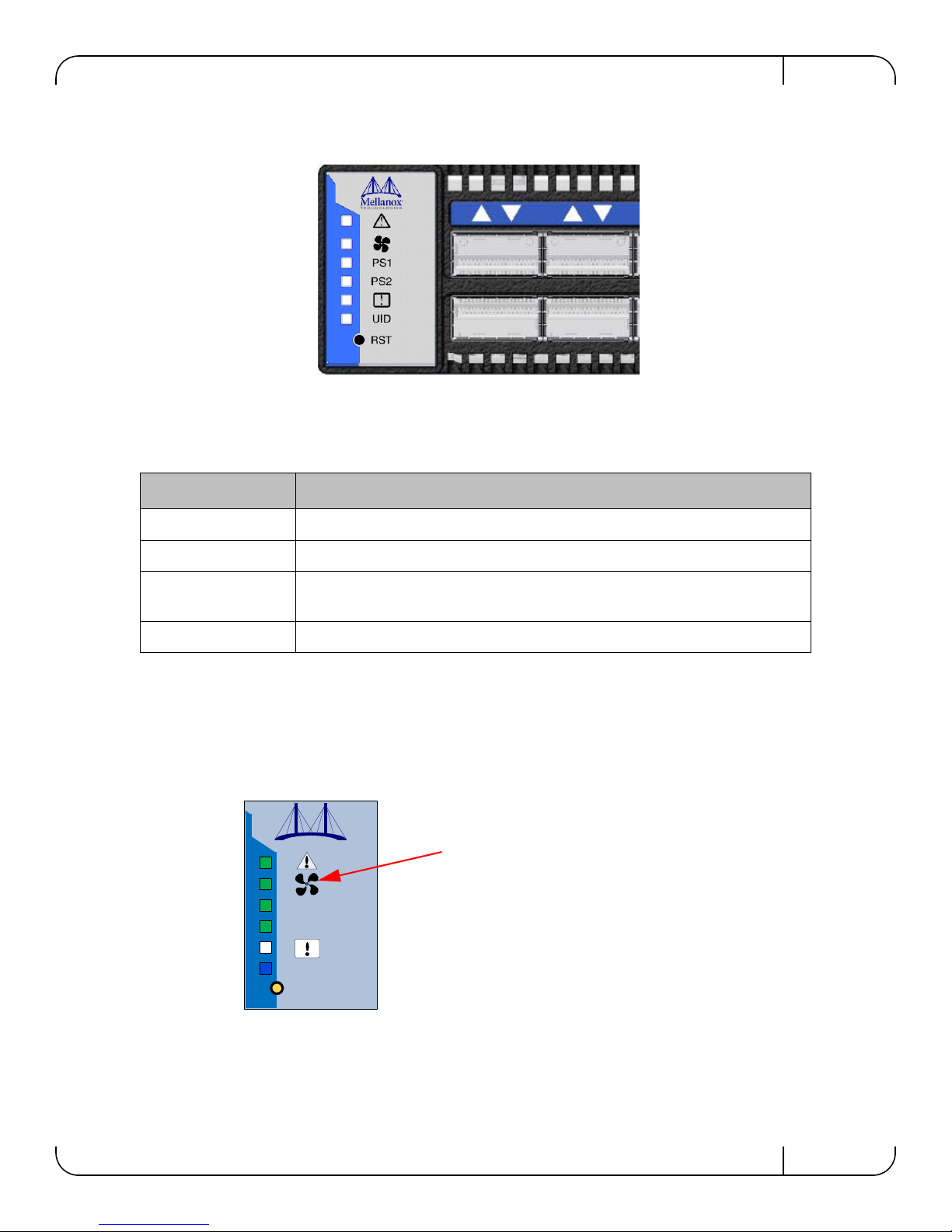
3.1.1.2 Fan Status Indicators
The indicator is located to the left of the connectors on the connector side panel.
Figure 6: Fan Status LED Connector Side
The LED indicator on the Fan Module is on the right side of the module.
Mellanox Technologies
17
Page 18
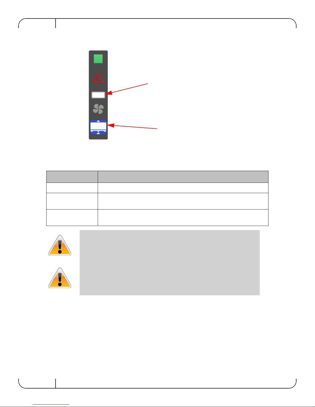
Figure 7: Fan Status LED Power side
!
This is a two color LED
Green — OK
Red — Major fault
Off — No power to the fans
Fan air flow indicator
The following fan status conditions are possible:
Table 4 - Fan Status LED Configurations
Basic Operation and InstallationRev 1.3
LED Configuration FAN LED
Solid Green OK – All fans are up and running
Solid Red Error – One or more fans is not operating properly. The system should be powered
down and troubleshoot the fan module.
Off Off – The fan unit is not receiving any power. Check that the fan unit is properly
and completely inserted.
All fans must be operating while the power supply is plugged in.
If the switch shuts down due to over temperature, unplug the switch, wait 5 minutes
and replug in the switch. For more information
3.1.1.3 Power Supply Status Indicators
TheSX10XX switch is available with one factory installed Power Supply Unit. A second Power
Supply Unit can be added to support hot-swap ability and to add redundancy. See
“Replacement Parts Ordering Numbers,” on page 59 for ordering part numbers.
See “Troubleshooting” on page 46.
Section F,
18
Mellanox Technologies
Page 19
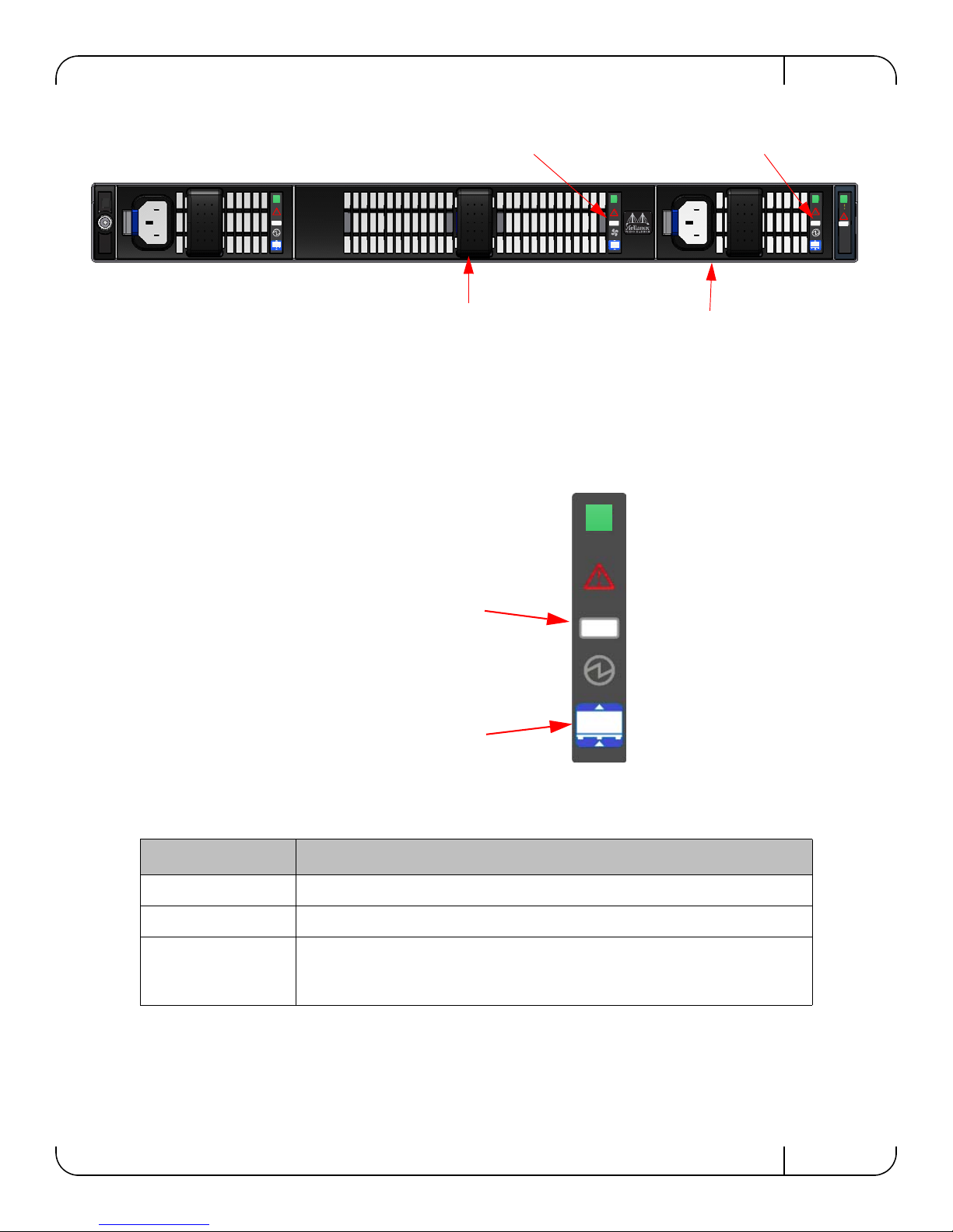
SwitchX 36-Port QSFP 40Gb/s Ethernet System Hardware User Manual Rev 1.3
OK
!
!
OK
OK
!
!
OK
12C
Primary Power Supply Unit
Fan Unit
PS unit 1 status LED
Fan status LED
This is a two color LED
Green — OK
Red — Major fault
Off — No power to the system
Power supply fan air flow
indicator
Figure 8: Power Side Panel
The primary power supply unit (PS1) is located on the right side of the power side panel, with
PS2 on the left side. Each PS unit has a single 2 color LED on the right side of the PS unit, that
indicates the internal status of the unit.
Figure 9: PS Unit Status LEDs
Table 5 - PS Unit Status LED Configurations
LED Color Status
Solid Green OK – The Power supply is delivering the correct voltage – 12VDC
Solid Red Error – The PS unit is not operational
Off Off – There is no power to the system (neither PS unit is receiving power). If one
PS unit is showing green and the second PS unit is unplugged it will show a red
indication.
Mellanox Technologies
19
Page 20
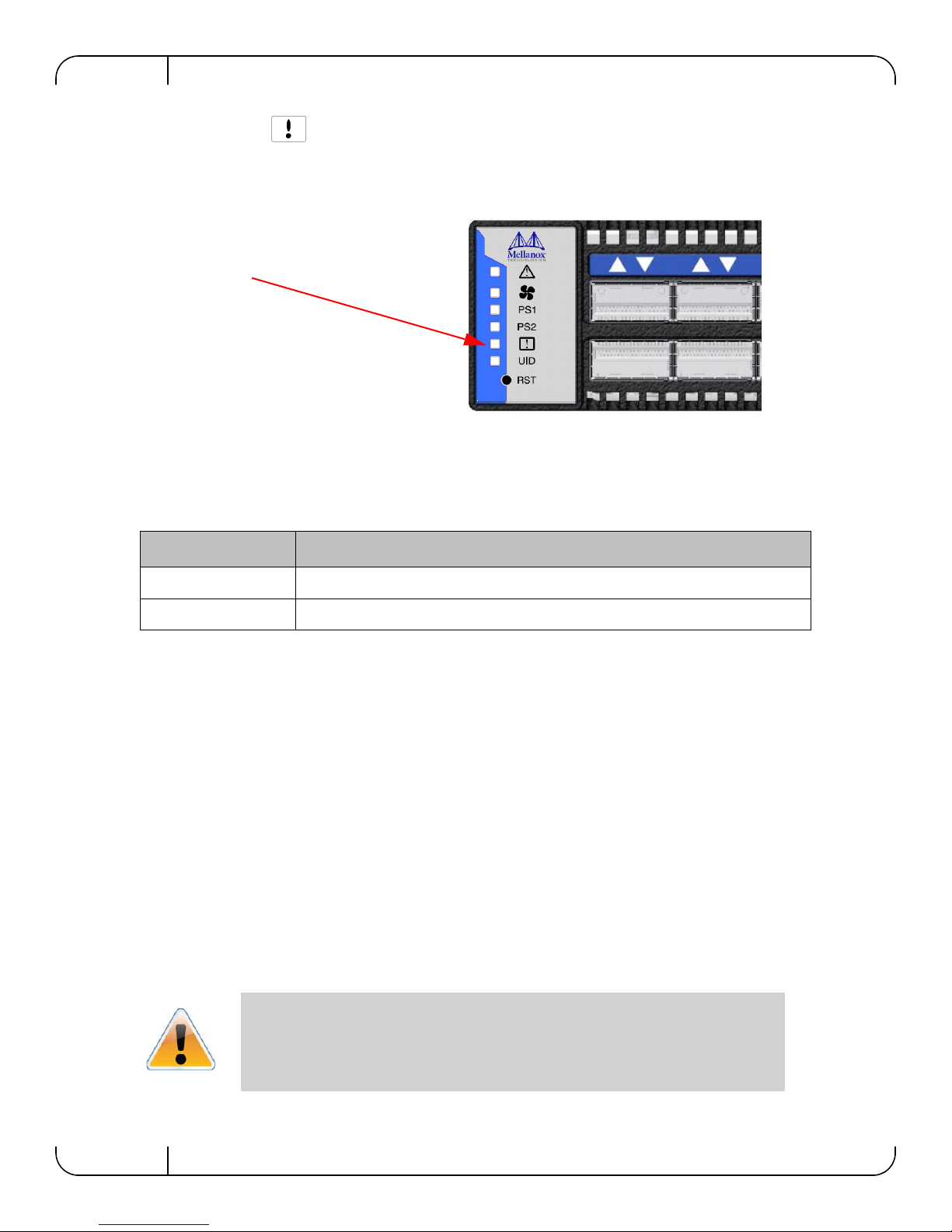
3.1.1.4 Bad Port LED
!
PS1
PS2
!
UID
RST
1
2
This is a one color LED
Flashing Orange — received symbol
error
UID
The Bad Port indicator is located on the left side of the connector side panel of the unit. The following Bad Port conditions are possible.
Table 6 - Bad Port LED Configurations
Basic Operation and InstallationRev 1.3
Figure 10: Bad Port LED
LED Configuration Description
Off OK – No symbol errors have been received in last few seconds
Flashing Orange Error – One or possibly more ports have just received a symbol error
This LED shows symbol errors. Possible causes for this are:
• Bad cable
• Bad connection
• Bad connector
This LED lights up when one or more ports is receiving a symbol error. The LED immediately
goes off until the next symbol error is received.
3.1.1.5 UID LED Switch Identifier
The UID LED is a debug feature that lights a blue LED on the switch connector side panel for
ease in finding a particular switch.
3.1.2 Reset Button
On the connector side panel under the system LEDs is a reset button. This reset button requires a
tool to be pressed.
20
Mellanox Technologies
DO NOT use a sharp pointed object such as needle or push pin for pressing the Reset
button. Sharp objects can cause damage, use a flat object to push the reset button.
Page 21
SwitchX 36-Port QSFP 40Gb/s Ethernet System Hardware User Manual Rev 1.3
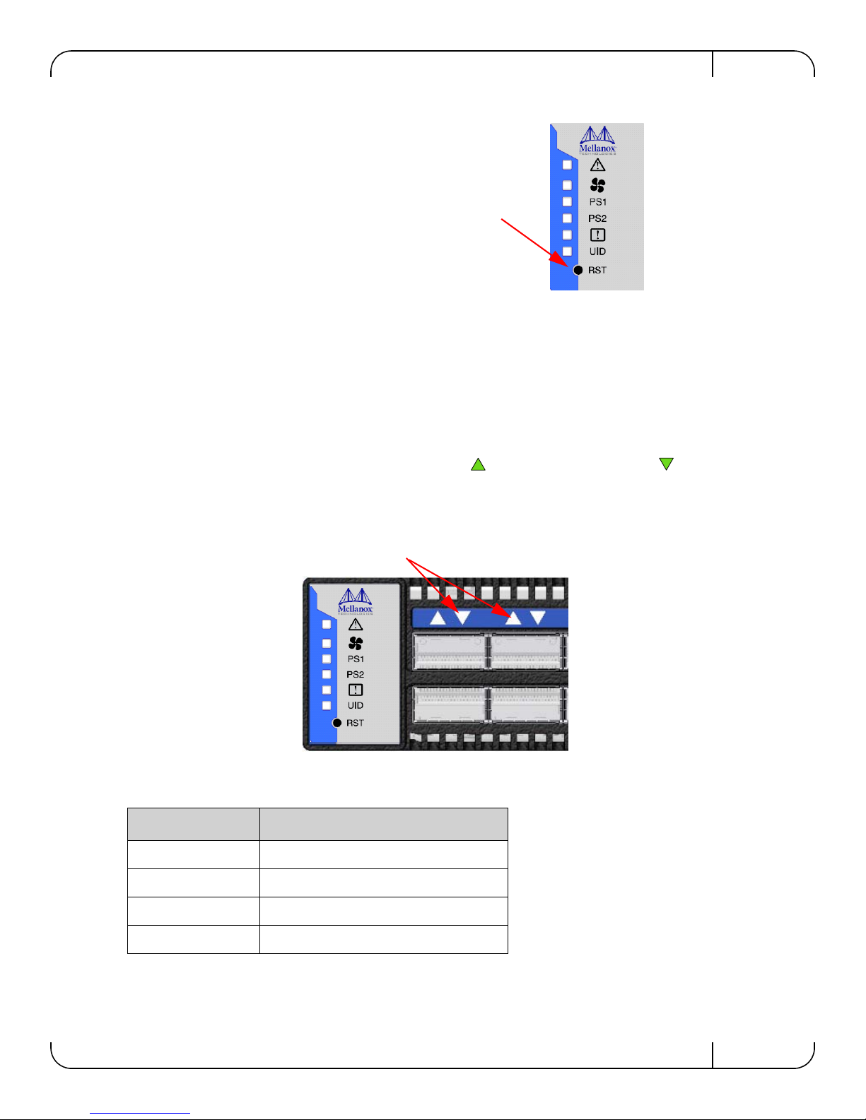
Press the reset button to reset the main and
management CPUs and to delete the existing
password.
!
PS1
PS2
!
UID
RST
1
2
Port LEDs
Figure 11: Reset Button
This button resets both the CPU of the switch device and the CPU of the management module. It
thereby resets all of the ports by bringing them down and powering them up when the button is
pushed. A quick push of this button performs this reset. When the button is held down for 15 sec
onds the switch is reset and the password is deleted. You will then be able to enter without a password and make a new password for the user “admin”.
3.1.2.1 Port Connector LED Indicators
Above the ports are two LEDs one for the upper port and one for the lower port . The following table shows the port status according to the LED indication.
Figure 12: Port LEDs
Table 7 - Port Connector Ph ysical and Logical Link Indications for Ethernet
LED Configuration LED Description
Off Physical link down / Default
Solid Green Physical link up no traffic
Flashing Green Physical link up with traffic
Flashing Orange Physical errors
Mellanox Technologies
21
Page 22
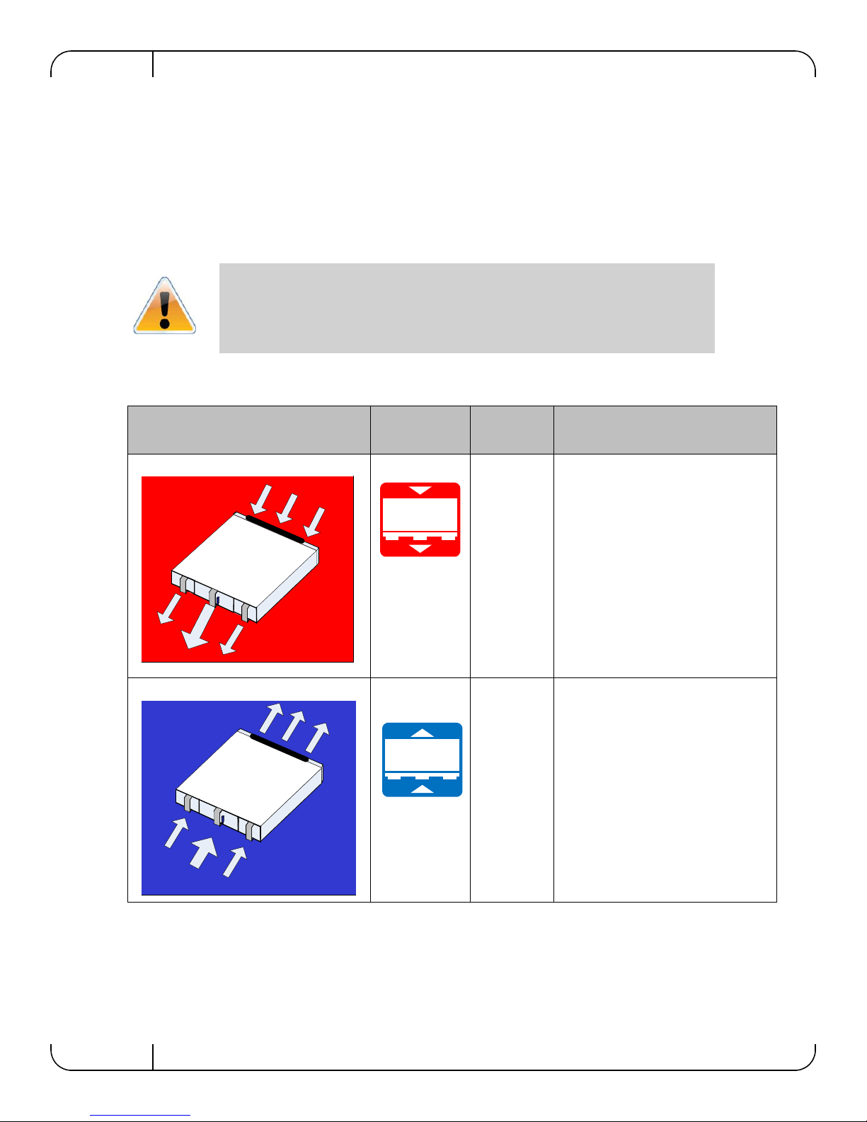
3.2 Air Flow
These switches can come with two air flow patterns. The two patterns are:
• Connector side inlet to power side outlet
• Power side inlet to connector side outlet
The air flow is specified in the product model number. See “Mellanox Part Numbering Legend”
on page 10. On the PS unit and fan modules the air flow direction can be seen on the power side
panel.
Table 8 - Air Flow Direction
Basic Operation and InstallationRev 1.3
All PS units must have the same air flow as the fan module.
Direction Label
OPN
Designation
R
F
Description
Connector side inlet to power side
outlet
Power side inlet to connector side
outlet
3.3 QSFP Cable Power Budget Classification
All SwitchX QSFP switches are designed for active cables with a max power per module of 2W.
Typical power per port is 1.3W.
22
Mellanox Technologies
Page 23
SwitchX 36-Port QSFP 40Gb/s Ethernet System Hardware User Manual Rev 1.3
I2C
36
35
MGT
1
2
SX1035
CONSOLE
34
33
3.4 Interfaces
3.4.1 Port Connector Interfaces
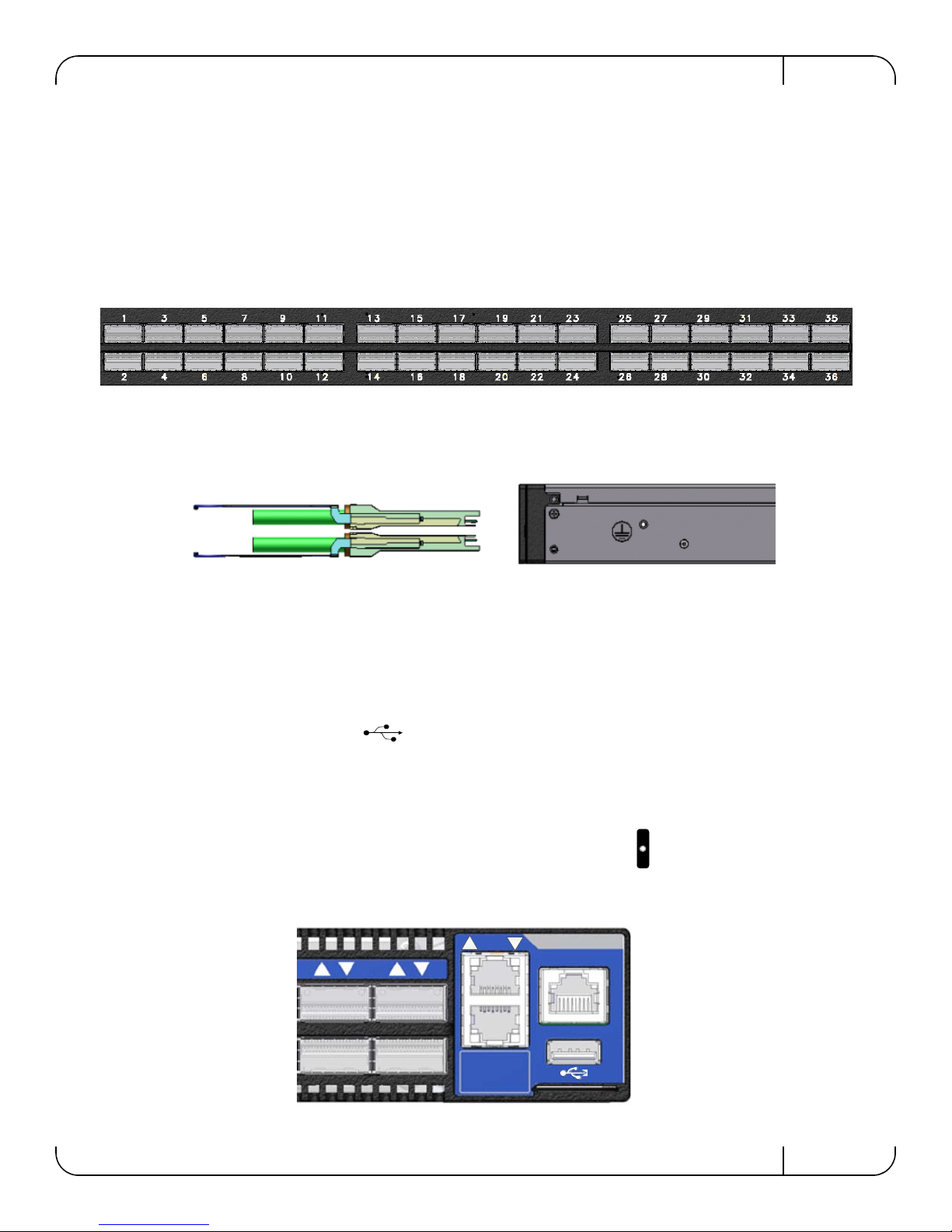
The connector side of the switch has 36 QSFP ports. These are placed in two rows, 18 ports to a
row. The ports are labelled as shown in
row. See Figure 14 for bottom row - top row port orientation.
Figure 14: Top and Bottom Port Orientation
Figure 13. The bottom row ports are flipped from the top
Figure 13: Port Numbering
3.4.2 Management and Firmware Updating Interfaces
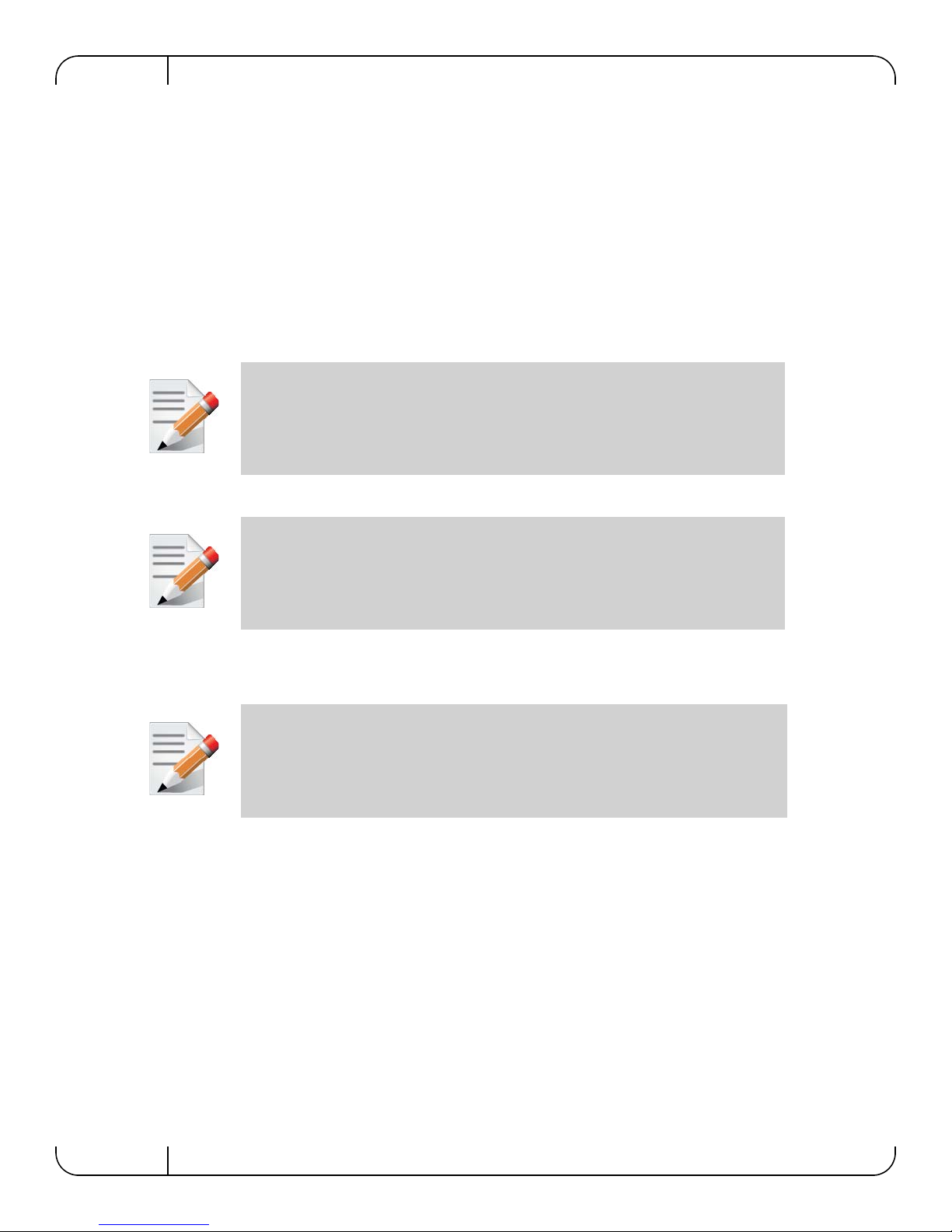
There are five interfaces to connect to the SX103X:
• 2 X 100M/1Gb Ethernet connectors labelled “MGT”
• 1 USB port that is labelled
This interface can be used to update software or firmware.
• 1 connector that is labelled “CONSOLE”
Use this connector to connect to the host PC.
• 1 I2C banana connector on the power supply side for FAE use only
Figure 15: Management Interfaces
Mellanox Technologies
23
Page 24
3.4.2.1 RJ-45 Connector (CONSOLE)
The port labelled “CONSOLE” is for a local host connection to the management module. This is
used the first time the switch is connected. A harness is included in the package to connect to a
DB9 connection on a host PC. Connecting to a local host PC and following the instructions in the
Installation Guide, “Configuring the Switch for the First Time”, must be done before any remote
management is available. For the Socket pinout see
on page 58.
3.4.2.2 RJ-45 Ethernet Connector (MGT)
The Ethernet connection labelled “MGT” provides access for remote management. The switch
can be connected to any Ethernet port.
Each Ethernet connector gets connected to Ethernet switches. These switches must be
configured to 100M/1G auto-negotiation.
3.4.2.3 USB interface
Basic Operation and InstallationRev 1.3
“RJ-45 CONSOLE and Ethernet interfaces”
The USB interface can be used to update the MLNX-OS™ Web User Interface
(WebUI) or MLNX-OS Command Line Interface (CLI)
There is a single USB connector. This connector can be used to install software and or firmware
upgrades using a memory device that has a USB connector. This connector is USB 2.0 compli
ant.
USB 1.0 is not supported.
3.4.2.4 I2C Interface
There is an I2C connector on the far left of the power side of the switch. This interface is for
Debug and Troubleshooting only.
This connector can be used to install firmware upgrades, should
the firmware image be damaged and cann ot be upgraded through a host PC or remotely. This
interface is for support personnel and advanced users only.
3.5 Switch Platform Installation and Operation
Installation and initialization of the switch platform are straightforward processes, requiring
attention to the normal mechanical, power, and thermal precautions for rack-mounted equipment.
-
24
Mellanox Technologies
Page 25
SwitchX 36-Port QSFP 40Gb/s Ethernet System Hardware User Manual Rev 1.3
3.5.1 Installation Safety Warnings
For Safety Warnings in French see Section G,“Avertissements de sécurité d’installation
(French),” on page 60, for German see Section H,“Installation - Sicherheitshinweise (German),”
on page 64, and for Spanish see Section I,“Advertencias de seguridad para la instalación (Spanish),” on page 68.
1. Installation Instructions
Read all installation instructions before connecting the equipment to the power source.
2. Over-temperature
This equipment should not be operated in an area with an ambient temperature exceeding the maximum recommended: 45°C (113°F). Moreover, to guarantee proper air
flow, allow at least 8cm (3 inches) of clearance around the ventilation openings.
3. Stacking the Chassis
The chassis should not be stacked on any other equipment. If the chassis falls, it can
cause bodily injury and equipment damage.
4. Redundant Power Supply Connection - Electrical Hazard
This product includes a blank cover over the space for the redundant power supply. Do
not operate the product if the blank cover is not securely fastened or if it is removed.
5. During Lightning - Electrical Hazard
During periods of lightning activity, do not work on the equipment or connect or disconnect cables.
6. Copper Cable Connecting/Disconnecting
Copper cables are heavy and not flexible, as such they should be carefully attached to
or detached from the connectors. Refer to the cable manufacturer for special warnings
and instructions.
Mellanox Technologies
25
Page 26
7. Rack Mounting and Servicing
When this product is mounted or serviced in a rack, special precautions must be taken
to ensure that the system remains stable. In general you should fill the rack with equip
ment starting from the bottom to the top.
8. Equipment Installation
This equipment should be installed, replaced, or serviced only by trained and qualified
personnel.
9. Equipment Disposal
Disposal of this equipment should be in accordance to all national laws and regulations.
10. Local and National Electrical Codes
Basic Operation and InstallationRev 1.3
-
This equipment should be installed in compliance with local and national electrical
codes.
11. Hazardous Radiation Exposure
Caution – Use of controls or adjustment or performance of procedures other than those
specified herein may result in hazardous radiation exposure.
CLASS 1 LASER PRODUCT and reference to the most recent laser standards:
IEC 60 825-1:1993 + A1:1997 + A2:2001 and EN 60825-1:1994+A1:1996+ A2:20 01
12. UL Approved AC Power Cords
For North American power connection, select a power supply cord that is UL Listed
and CSA Certified
3 - conductor, [18 AWG], terminated in a molded on plug cap rated at 125 V, [15 A],
with a minimum length of 1.5m [six feet] but no longer than 4.5m
For European connection, select a power supply cord that is internationally
harmonized and marked “<HAR>”,
3 - conductor, minimum 0,75 mm2 wire, rated at 300 V, with a PVC insulated jacket.
The cord must have a molded on plug cap rated 250 V, 10 A.
26
Mellanox Technologies
Page 27
SwitchX 36-Port QSFP 40Gb/s Ethernet System Hardware User Manual Rev 1.3
13. Do Not Use the Switch as a Shelf or Work Space
Caution: Slide/rail mounted equipment is not to be used as a shelf or a work space.
14. WEEE Directive
According to the WEEE Directive 2002/96/EC, all waste electrical and electronic
equipment (EEE) should be collected separately and not disposed of with regular
household waste.
Dispose of this product and all of its parts in a responsible and environmentally
friendly way.
3.5.2 Mechanical Installation
The switch platform can be rack mounted and is designed for installation in a standard 19” rack.
The power side of the switch includes a hot-swap power supply module, a blank cover for an
optional second PS unit for redundancy, and a hot-swap fan tray. There are two possible air flow
directions. Be sure that the switch air flow direction is compatible with your system, rack, and PS
units. The connector side of the switch has the QSFP ports, system LEDs, and management con
nection ports.
-
The switch platform contains auto-sensing 100 - 240 VAC connections for all possible PS units.
The installer should use a rack capable of supporting the mechanical and environmental charac-
teristics of a fully populated platform.
The rack mounting holes conform to the EIA-310 standard for 19-inch racks. Take precautions to guarantee proper ventilation in order to maintain good airflow at ambient
temperature. Cable routing in particular should not impede the air exhaust from the
chassis.
3.5.2.1 Installation Kits
There are two Installation kit options. One long and one short. Both the long and the short
switches can be mounted using the long rail kit.
Table 9 - Installation Kit According to Rack Size
Kit OPN Rack Size
MSX60-BKIT 40-60 cm
MSX60-BKIT 40-60 cm deep
MSX60-SKIT 60-80 cm deep
Mellanox Technologies
27
Page 28
3.6 Package Contents and Installation
Before you install your new SX103X switch, unpack the system and check to make sure that all
the parts have been sent, check this against the parts list below. Check the parts for visible dam
age that may have occurred during shipping.
The switch comes packed with the following items:
• 1 X – switch
• 1 X – installation kit
• 1 X – power cable for each PS unit – Type C13-C14
• See “Replacement Parts Ordering Numbers” on page 59 to order power cords for various
countries
• A single power cord for each power supply unit can be ordered at no extra charge
• 1 X – Harness
• HAR000028 – Harness RS232 2M cable – DB9 to RJ-45
• 1 X – Quick Start Guide
• 1 X – China RoHS statement
Basic Operation and InstallationRev 1.3
-
If anything is damaged or missing, contact your customer representative immediately.
For customer support go to:
www.mellanox.com =>Support => Customer Support Portal Login
3.6.1 Installing the Switch in the Rack
Tools and Customer Supplied Parts:
• Phillips Screwdrivers #1 and #2 • Grounding screw
• ESD strap • Grounding wire sufficient to reach a valid ground.
• ESD mat
For racks from 60cm to 80cm deep either use the standard depth switches with the long rail kit or
the short switches with the long rail kit.
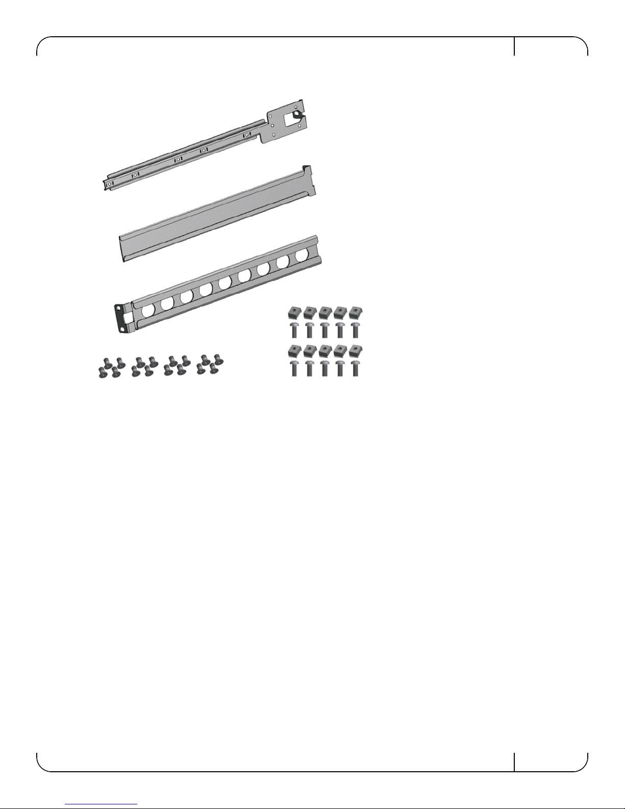
Parts included in the rail kit:
• 2 rails • 16 recessed flat head screws You will have extras!
• 2 rail slides • 10 caged nuts
• 2 switch slides • 10 pan head screws M6
28
Mellanox Technologies
Page 29
SwitchX 36-Port QSFP 40Gb/s Ethernet System Hardware User Manual Rev 1.3
Switch slide x2
Rail x2
Rail slide x2
Figure 16: Rack Rail Kit Parts
1. Place the ESD mat on the floor where you will be working and put on the ESD strap. Make
sure the ESD strap is touching your skin and that the other end is connected to a verified
ground.
2. Choose which side of the switch you want even with the rack vertical support. Either the side
with the power supply units or the side with the QSFP connectors can be even with one of the
vertical rack supports.
Mellanox Technologies
29
Page 30
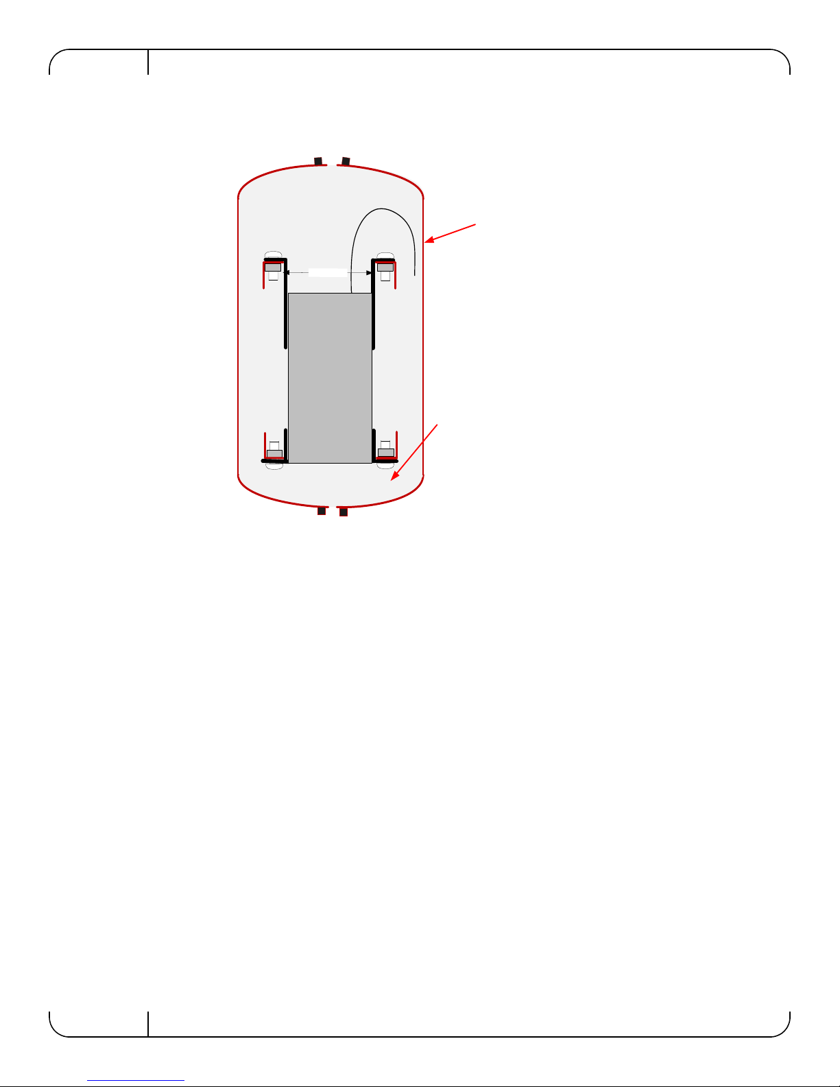
Figure 17: Placement of Switch in Rack
1
9
"
(
4
8
2
.
6
m
m
)
Switch
Connector side
Spine side
Cable with
recomm ended
bending radius
Insuffic ien t ro o m fo r
recommended b ending
radius
Doors
Doors
Basic Operation and InstallationRev 1.3
Things to consider before choosing where to mount the rails and rail slides.
The distance between the rack and the door can be as little as 4 cm on one side of the rack and as
much as 18 cm on the other side of the rack. Keep in mind that there can be as many as 36 cables
connected to the switch.
30
• Do you want the connector side recessed in the rack to allow for a larger cable bending
radius? It is possible to recess the connector side by 5cm by optional placement of the
switch rails. See
• Will the connector side be recessed past other equipment in the rack and will this be problematic?
• The installation kit allows for a 2” recess of the switch past the vertical support.
Figure 18,“Mounting Options”.
Mellanox Technologies
Page 31
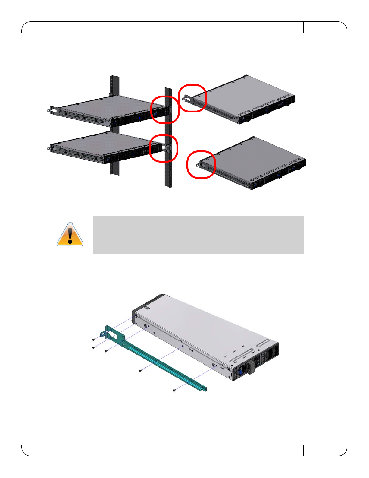
SwitchX 36-Port QSFP 40Gb/s Ethernet System Hardware User Manual Rev 1.3
5 screws per side are needed for the short switch
7 screws per side are needed for the standard switch
There are 16 screws in the kit; you will have left over screws.
Figure 18: Mounting Options
3. Decide which mounting option you want to use.
To use the rail kit to transfer the power cord from the connector side to the power side
go now to
“Transferring the Power Cord” on page 54.
4. Screw the switch slides onto the switch. Use 5 flat head screws for short switches and 7
screws for standard depth switches, to connect each switch slide.
Figure 19: Screwing on the Rail
Mellanox Technologies
31
Page 32
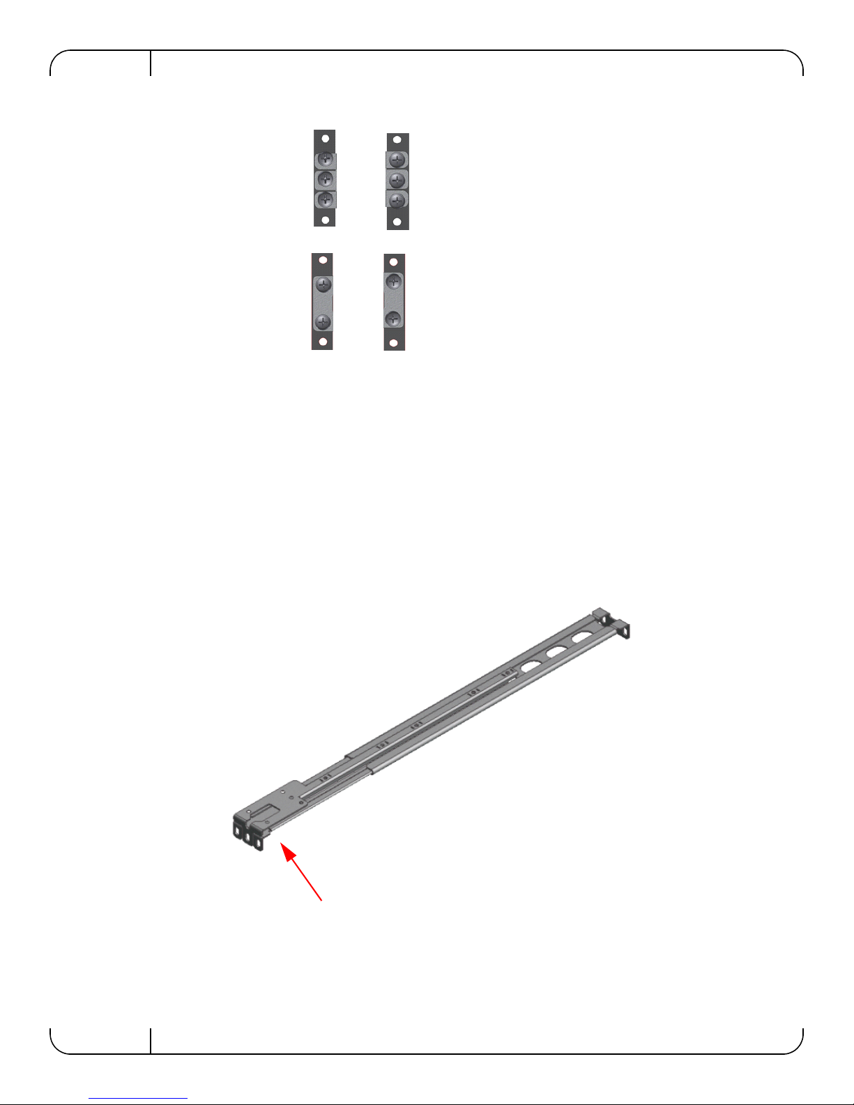
Basic Operation and InstallationRev 1.3
Side you will slide
the switch into
Second side
This side of the rail kit goes on the side of the rack you will
slide the switch into. This is the same side of the switch that
will be next to the vertical support.
Figure 20: Inserting the Caged Nuts
5. Clip 6 caged nuts into the holes in the rack on the side of the rack you will be sliding the
switch into. Check that both sides of the switch, power side and connector side, are at the
same level in the rack.
6. Clip 4 more caged nuts into the holes on the opposite side of the rack. Check that both sides of
the switch, left and right, are the same level in the rack.
7. Slide the rail into the rail slide.
8. Using two of the bolts for each corner install the rails and rail slides in the rack. Do not
tighten the bolts yet.
Figure 21: Slide the Rail into the Rail Slide
32
Mellanox Technologies
Page 33
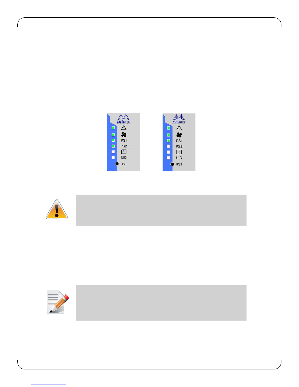
SwitchX 36-Port QSFP 40Gb/s Ethernet System Hardware User Manual Rev 1.3
Switch with 2 PSUs
Switch with 1 PSU
9. Slide the switch into the rails.
10.Tighten the bolts to 9.2 Nm or 81.5 pound inches.
11.Put the switch into place and screw the bolts into the nuts. Tighten the bolts to 9.2 Nm or 81.5
pound inches.
12.Ground the switch.
13.Plug in the power cables.
14. Check the Status LEDs and confirm that all of the LEDs show status lights consistent with
normal operation.
Figure 22: Status LEDs 5 Minutes After Power On
W arning: Any yellow or red status LEDs are cause for concern and must be dealt with
immediately.
It can take up to 5 minutes to boot up, during which time the status LED may indicate
red.
15.You can start connecting all of the cables to the switch.
3.7 Grounding the Switch
Check to determine if your local or national electrical codes require an external ground to all IT
components. If so, connect a ground wire to one of the casing screws and connect the other end to
a valid ground. If you choose to not use the ground screw, make sure that the rack is properly
grounded and that there is a valid ground connection between the chassis of the switch and the
rack. Test the ground using an Ohm meter.
Some national and/or local codes may require IT components to be bonded and externally grounded (not including the power cord ground). You must follow all national
and local codes when installing this equipment.
3.8 Power Connections and Initial Power On
The switch platform ships with one or power supply unit. For switches with only one unit
installed, a second PS unit may be installed at a later time. Each supply has a separate AC recep
-
Mellanox Technologies
33
Page 34
Basic Operation and InstallationRev 1.3
CAUTION
Risk of electric shock and energy
hazard. The two PS units are
independent.
Disconnect all power supplies to
ensure a powered down state
inside of the switch platform.
ACHTUNG
Gafahr des elektrischen
Schocks. Entferrnen des
Netzsteckers elnes Netzteils spannungsfrei. Um
alle Einhieten spannungsfrei zu machen sind die
Netzstecker aller Netzteile
zu entfernen
A TTENTION
Risque de choc et de danger
e’lectriques. Le de’branchment d’une seule alimentation
stabilise’e ne de’branch
uniquement qu’un module
“Alimentation Stabilise’e”.
Pour isoler completement le
module en cause, Il faut
de’brancher toutes les alimentations stabilise’es.
tacle. The input voltage is auto-adjusting for 100 - 240 VAC, 50-60Hz power connections. The
power cords should be standard 3-wire AC power cords including a safety ground and rated for
15A or higher.
Caution: The switch platform will automatically power on when AC power is applied.
There is no power switch. Check all boards, power supplies, and fan tray modules for
proper insertion before plugging in a power cable.
Caution: After inserting a power cable and confirming the green system status LED
light is on; make sure that the Fan Status indicator shows green.
If the fan status indicator is not green then unplug the power connection and check that
the fan module is inserted properly and that the mating connector of the fan unit is free
of any dirt and/or obstacles.
Caution: When turning off the switch, make sure ALL Connector LEDS are off to
ensure a powered down status.
Do not hot swap the power supply if your switch has only one power supply. You must
power down the system to replace the power supply unit when there is only one PS
unit in the switch.
Figure 23: Two Power Inlets - Electric Caution Notifications
34
Mellanox Technologies
Page 35
SwitchX 36-Port QSFP 40Gb/s Ethernet System Hardware User Manual Rev 1.3
OK
!
!
OK
OK
!
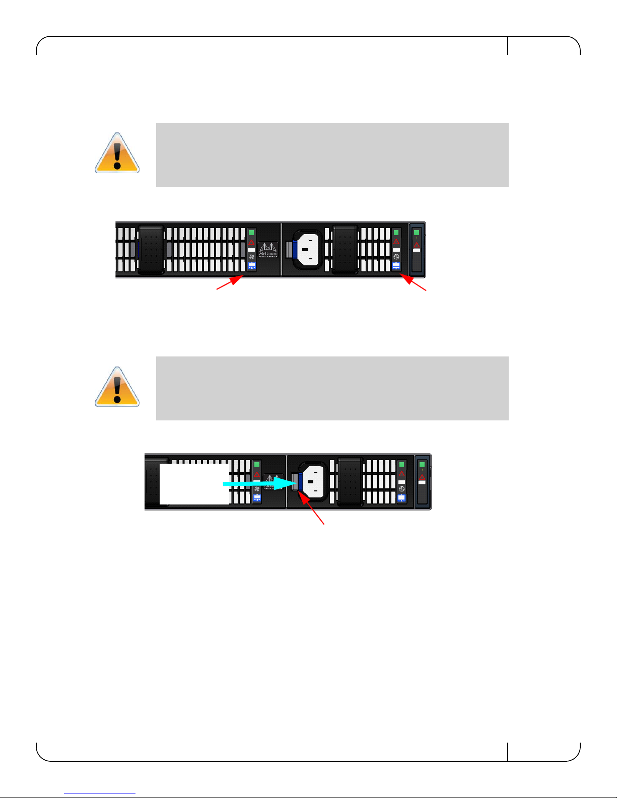
PS unit Air flow directionFan Air flow direction
OK
!
!
OK
OK
!
Latch release
Push Here
3.9 Extracting and Inserting the Power Supply Unit
With both power supplies installed in the redundant configuration, either PS unit may be
extracted without bringing down the system.
Make sure that the PS unit that you are NOT replacing is showing all green, for both
the PS unit and status indicators.
Figure 24: Fan and PS unit Air Flow Direction
Power supply units have directional air flows similar to the fan module. The Fan module airflow must coincide with the airflow of all of the PS units. If the PS unit airflow
direction is different from the fan module airflow direction the switch internal temper
ature will be affected.
Figure 25: Power Supply Unit Extraction
-
Mellanox Technologies
35
Page 36
Basic Operation and InstallationRev 1.3
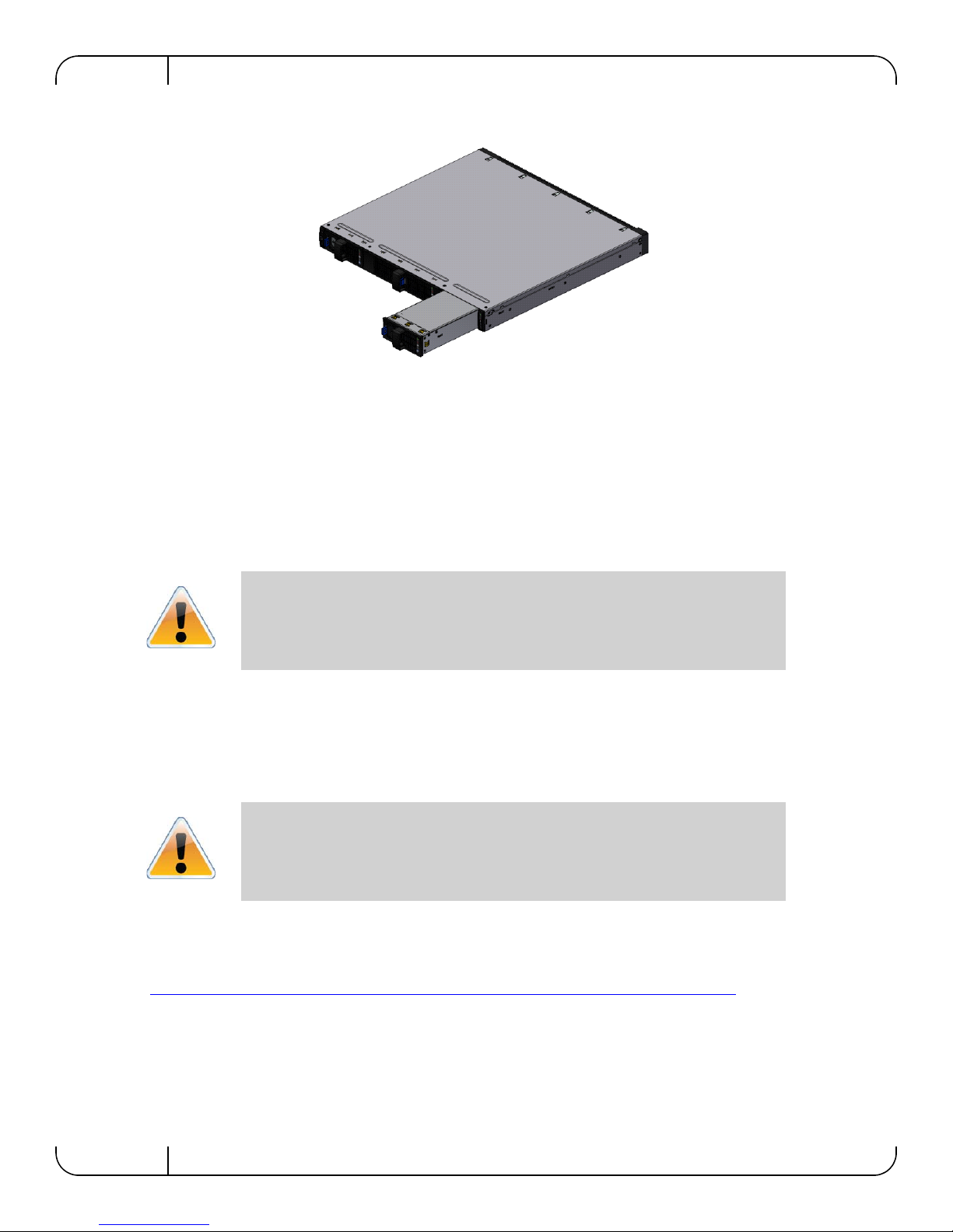
Figure 26: PS Unit Pulled Out
To extract a PS unit:
1. Remove the power cord from the power supply unit.
2. Grasping the handle with your right hand, push the latch release with your thumb while pulling the handle outward. As the PS unit unseats, the PS unit status indicators will turn off.
3. Remove the PS unit.
To insert a PS unit:
1. Make sure the mating connector of the new unit is free of any dirt and/or obstacles.
Do not attempt to insert a PS unit with a power cord connected to it.
2. Insert the PS unit by sliding it into the opening until a slight resistance is felt.
3. Continue pressing the PS unit until it seats completely. The latch will snap into place confirming the proper installation.
4. Insert the power cord into the supply connector.
5. Insert the other end of the power cord into an outlet of the correct voltage.
The green PS unit indicator should light. If not, repeat the whole procedure to extract
the PS unit and re-insert it.
3.10 Supported Approved Cables
For a list of approved cables for this switch see
http://www.mellanox.com/related-docs/user_manuals/Mellanox_approved_cables.pdf
3.11 Splitting the Data Stream Using Breakout (Fanout) Cables
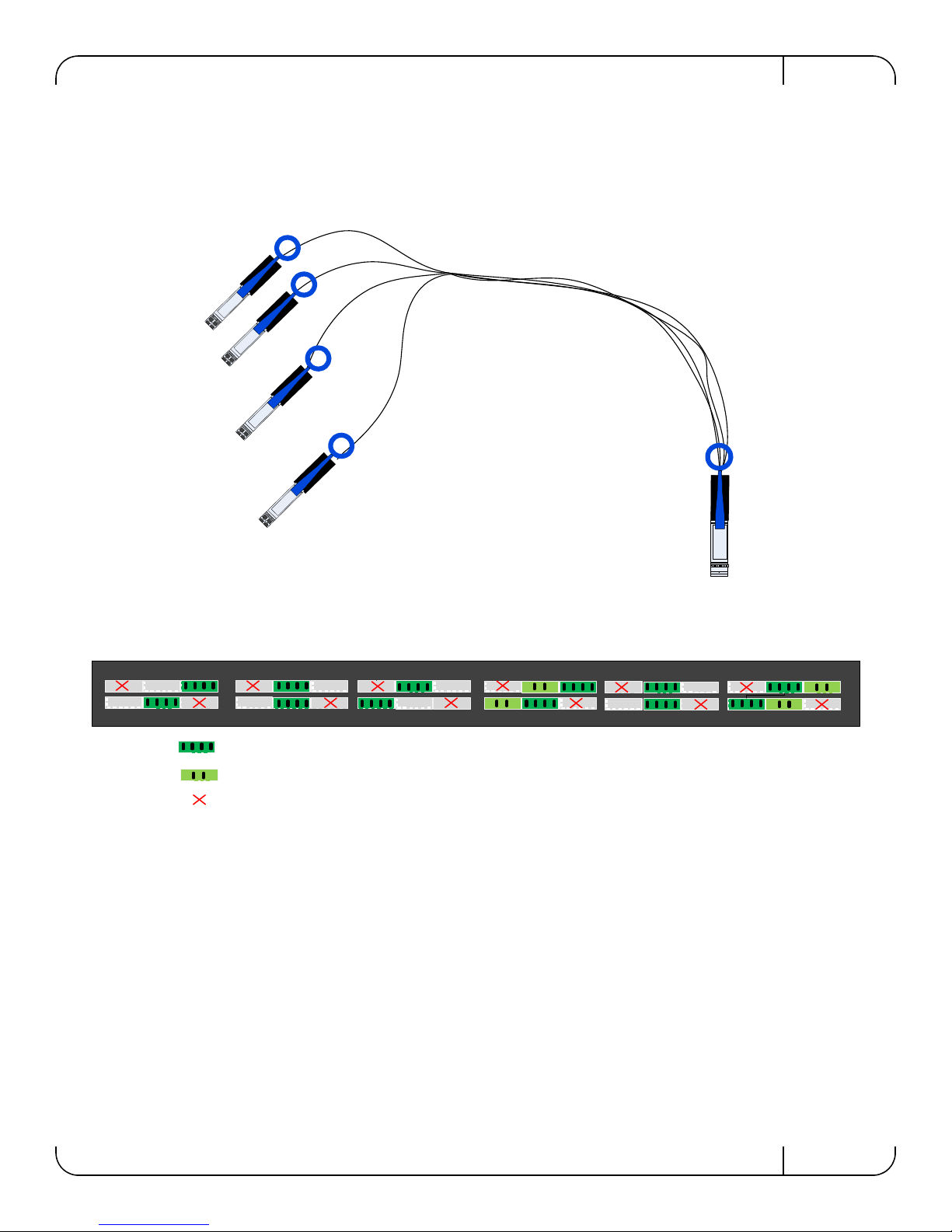
Specific ports can be split by using a QSFP 1X4 breakout cable to split one
40 Gb/s port into 4 lanes (4 SFP+ connectors 10Gb/s each). These 4 lanes then go, one lane to
each of the 4 SFP+ connectors. Some ports can be split into 2 10 Gb/s ports, using lanes 1 and 2
36
Mellanox Technologies
Page 37
SwitchX 36-Port QSFP 40Gb/s Ethernet System Hardware User Manual Rev 1.3
123
4
5
6
7
89101112131415161718
1920212223242526272829303132333435
36
This port can be split into 4 10Gb/s SFP+
This port can be split into 2 10Gb/s SFP+
This port is unmapped according to the Port Splitting Table
The maximum 10 Gb/s Ethernet ports configurable with this
switch is 64.
only. When a QSFP port is split into 2 10Gb/s ports then only SFP+ connectors #1 and #2 are
used. Connectors #3 and #4 are left unconnected. Using
Figure 28 and Table 10, with breakout
cables you can achieve 64 ports of 10Gb/s.
Figure 27: Breakout or Fanout Cable
Figure 28: Port Splitting Options
When using a port to split a data stream into 4-10Gb/s data streams (four lanes) one of the other
ports on the switch will be disabled (unmapped). See
Table 10 to determine:
• which ports can be split into 4
• which ports can be split into 2
• which ports will be unmapped due to a 1X4 split
• When using this feature you MUST go into the MLNX-OS chassis management system
and reconfigure the individual ports to split-2 or split -4. See the MLNX-OS CLI User
Manual for instructions on port configuration.
Mellanox Technologies
37
Page 38
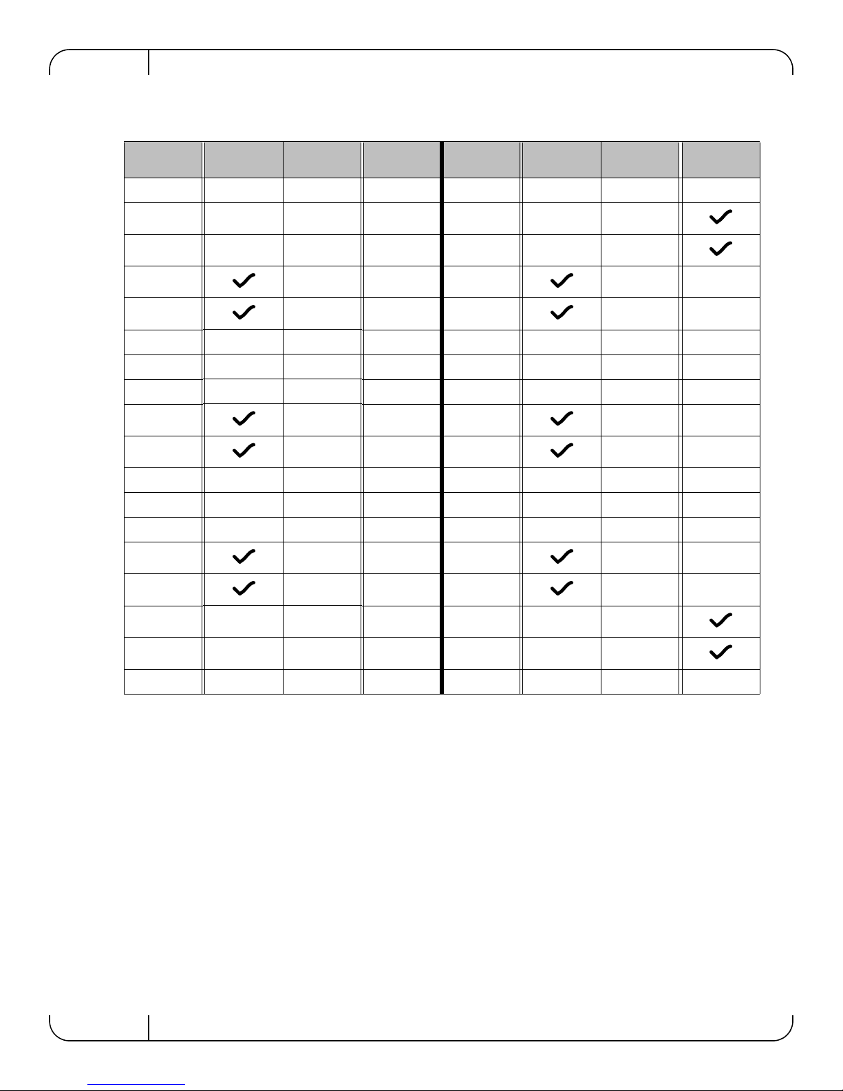
Table 10 - Port Splitting Options
Basic Operation and InstallationRev 1.3
Port #
Can be split
to 4
T urns off port #Can be split
to 2
Port # Can be split
to 4
T urns off port #Can be split
1 — — 19 —
2 — — 20 —
3 — — 21 —
4 1 — 22 19 —
5 6 — 23 24 —
6 — — 24 — —
7 — — 25 — —
8 — — 26 — —
9 12 — 27 30 —
10 7 — 28 25 —
11 — — 29 — —
12 — — 30 — —
13 — — 31 — —
to 2
14 13 — 32 31 —
15 18 — 33 36 —
16 — — 34 —
17 — — 35 —
18 — — 36 — —
38
Mellanox Technologies
Page 39
SwitchX 36-Port QSFP 40Gb/s Ethernet System Hardware User Manual Rev 1.3
12345
6
7
89101112131415161718192021222324252627282930313233343536
12345
6
7
89101112131415161718192021222324252627282930313233343536
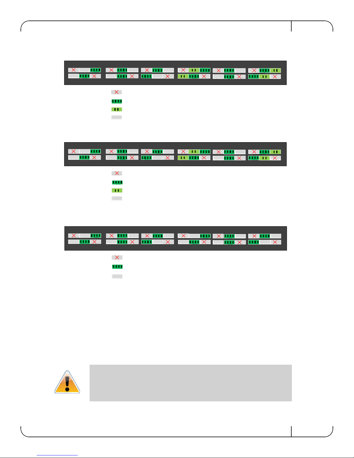
64 X10 GbE
12 x 40GbE ports split to 4 10GbE ports = 48 10GbE ports
4 x 40GbE ports split to 2 10GbE ports = 8 10GbE ports
12 x 40GbE ports blocked = 00 10GbE ports
8 x 40GbE ports used as 10GbE ports = 8 10GbE ports
Total = 64 x 10GbE ports
12 x 40GbE ports split to 4 10GbE ports = 48 10GbE ports
4 x 40GbE ports split to 2 10GbE ports = 8 10GbE ports
12 x 40GbE ports blocked = 00 10GbE ports + 00 40GbE ports
8 x 40GbE ports used as 40GbE ports = 8 x 40GbE ports
Total = 56 x 10GbE and 8 x 40GbE ports
12345
6
7
89101112131415161718192021222324252627282930313233343536
12 x 40GbE ports split to 4 10GbE ports = 48 10GbE ports
12 x 40GbE ports blocked = 00 10GbE ports + 00 40GbE ports
12 x 40GbE ports used as 40GbE port s = 12 40GbE ports
Total = 48 x 10GbE and 12 x 40GbE
56 x 10GbE and 8 x 40GbE
48 x 10GbE and 12 x 40GbE
DO NOT USE
THESE PORTS
DO NOT USE
THESE PORTS
DO NOT USE
THESE PORTS
Figure 29: 3 Examples of Port Mapping Assignment
3.12 Cable Installation
All cables can be inserted or removed with the unit powered on. To insert a cable, press the connector into the port receptacle until the connector is firmly seated. The LED indicator, corresponding to each data port, will light when the physical connection is established (that is, when
the unit is powered on and a cable is plugged into the port with the other end of the connector
plugged into a functioning port). After plugging in a cable, lock the connector using the latching
mechanism particular to the cable vendor. When a logical connection is made the LED will
change to green. When data is being transferred the light will blink green.
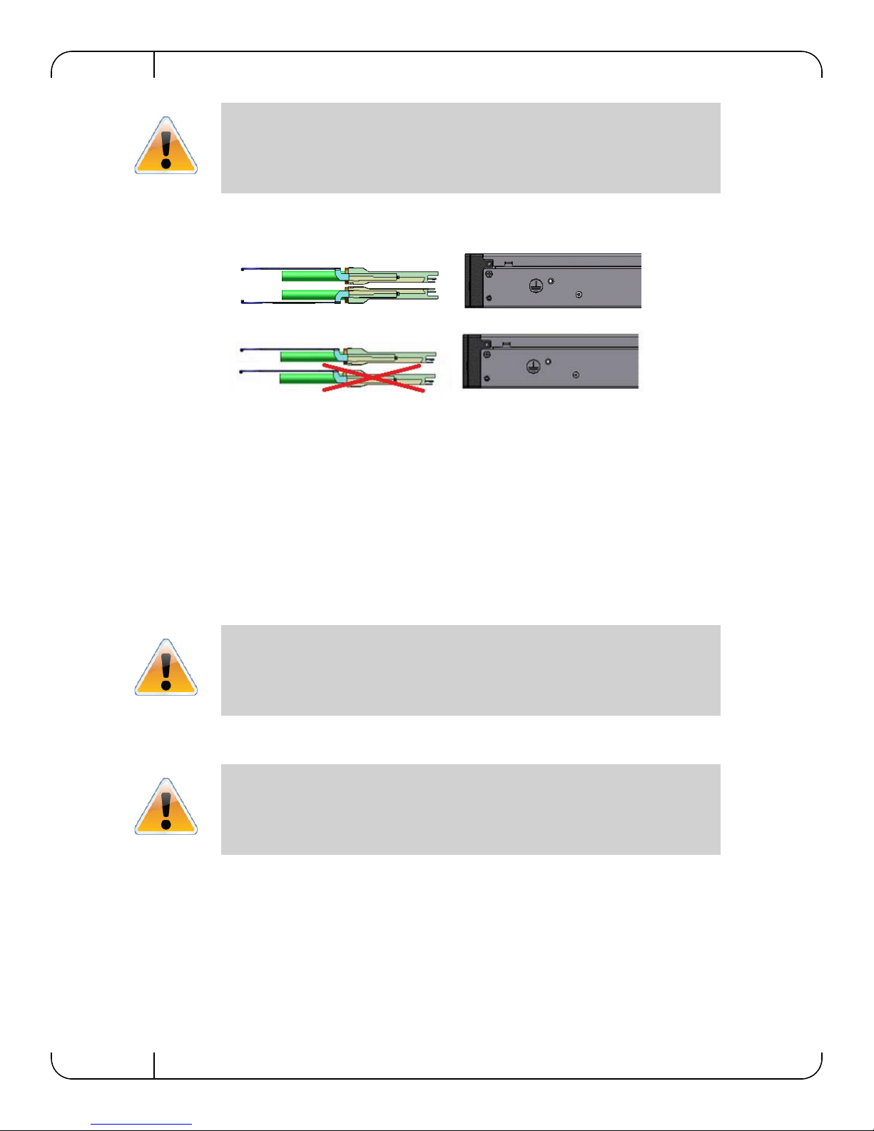
Do not force the cable into the cage with more than
40 newtons / 9.0 pounds force / 4 kg force. Greater insertion force may cause damage
to the cable or the cage.
Mellanox Technologies
39
Page 40
Basic Operation and InstallationRev 1.3
Cables in the bottom row should be inserted up side down in relation to the how the
cables are inserted in the top row.
Figure 30: Top and Bottom Ports
T o remove, disengage the locks and slowly pull the connector away from the port receptacle. The
LED indicator for that port will turn off when the cable is unseated.
Care should be taken not to impede the air flow through the ventilation holes next to the connector ports. Cable lengths should be used which allow for routing horizontally around to the side of
the chassis before bending upward or downward in the rack.
3.13 Extracting and Inserting the Fan Unit
This switch can operate indefinitely with one of the three fans in the fan module inoperable so
long as the ambient temperature is below 45° Celsius.
Operation without a fan unit should not exceed two minutes.
During fan hot-swap, if both indicators are OFF then the fan unit is disconnected.
There are two possible air flows for the fan unit. The air flow depends on the switch model. See
“Air Flow” on page 22 for an explanation of the model numbers and labels.
Make sure that the fans have the air flow that matches the model number. An air flow
opposite to the switch design will cause the switch to operate at a higher (less than
optimal) temperature.
40
Mellanox Technologies
Page 41
SwitchX 36-Port QSFP 40Gb/s Ethernet System Hardware User Manual Rev 1.3
OK
!
!
OK
OK
!
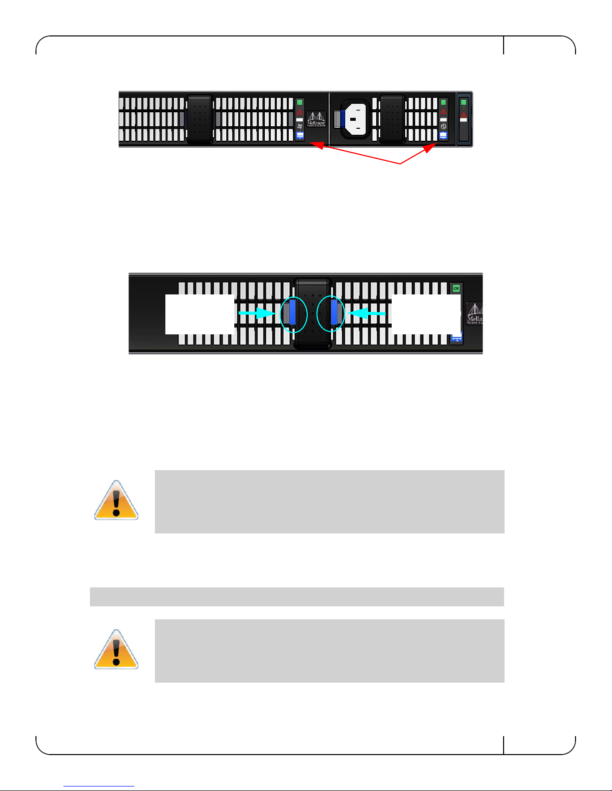
These air flow labels must be the same
These two latches must be pushed towards each other at the
same time while the module is pulled out.
Push Here Push Here
Figure 31: Air Flow Labels
To extract a Fan Unit
1. Using two fingers, push both latch releases towards each other simultaneously while pulling
the fan module out of the switch. As the fan unseats, the fan status indicator will turn off.
Figure 32: Fan Module Latches
To insert a FAN Unit:
1. Make sure the mating connector of the new unit is free of any dirt and/or obstacles.
2. Insert the fan unit by sliding it into the opening until slight resistance is felt. Continue pressing the fan unit until it seats completely.
The green fan status indicator should light. If not, extract the fan unit and reinsert it.
After two unsuccessful attempts to install the fan unit, power off the switch before
attempting any system debug.
3.14 Switch Shut Down Procedure
To shut down the switch run the command:
Reload halt [noconfirm]
The switch cannot be restarted remotely!
T o restart the switch you must physically go to the switch and un plug and plug
in the power cord.
Mellanox Technologies
41
Page 42
3.15 Disassembly of the Switch from the Rack
To disassemble the switch from the rack:
1. Unplug and remove all connectors.
2. Unplug all power cords.
3. Remove the ground wire.
4. Unscrew the 2 bolts from the side of the switch with the bracket.
Support the weight of the switch when you remove the screws so that the switch does
not fall.
5. Slide the switch from the rack.
6. Remove the rail slides from the rack.
7. Remove the ten caged nuts.
3.16 Disposal
Basic Operation and InstallationRev 1.3
According to the WEEE Directive 2002/96/EC, all waste electrical and electronic
equipment (EEE) should be collected separately and not disposed of with regular
household waste.
Dispose of this product and all of its parts in a responsible and environmentally
friendly way.
Follow the instructions found in the Mellanox Web site at mellanox.com for proper instructions
to disassemble and dispose of the Switch according to the WEEE directive.
3.17 Resetting the Switch
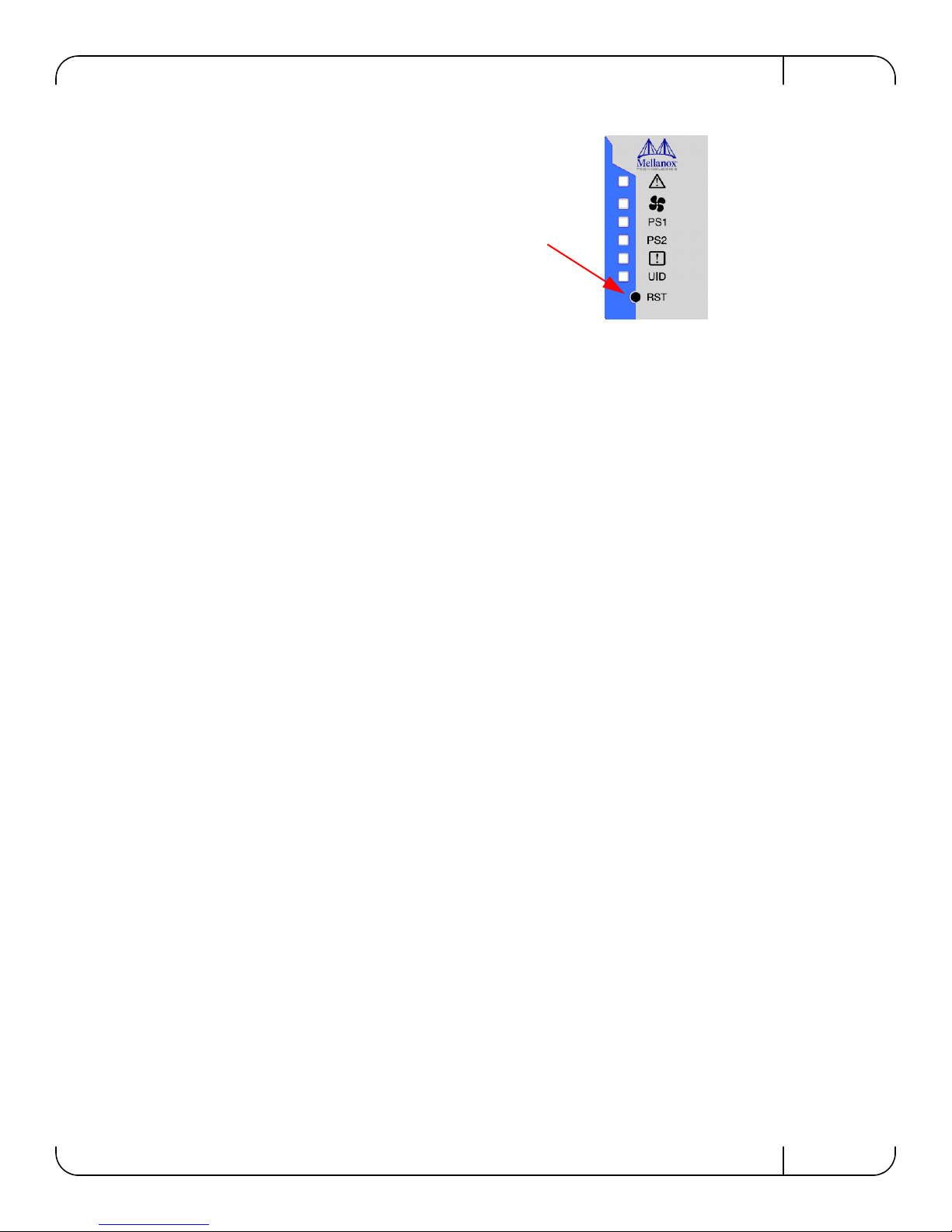
On the connector side panel under the system LEDs is a reset button. This reset button requires a
tool to be pressed.
DO NOT use a sharp pointed object such as needle or push pin for pressing the Reset
button. Sharp objects can cause damage, use a flat object to push the reset button.
42
Mellanox Technologies
Page 43
SwitchX 36-Port QSFP 40Gb/s Ethernet System Hardware User Manual Rev 1.3
Press the reset button to reset the main and
management CPUs and to delete the existing
password.
Figure 33: Reset Button
This button resets both the CPU of the switch device and the CPU of the management module. It
thereby resets all of the ports by bringing them down and powering them up when the button is
pushed. A quick push of this button performs this reset. When the button is held down for 15 sec
onds the switch is reset and the password is deleted. You will then be able to enter without a password and make a new password for the user “admin”.
Mellanox Technologies
43
Page 44
4 Management and Tools Overview
36
35
MGT
1
2
SX1036
CONSOLE
34
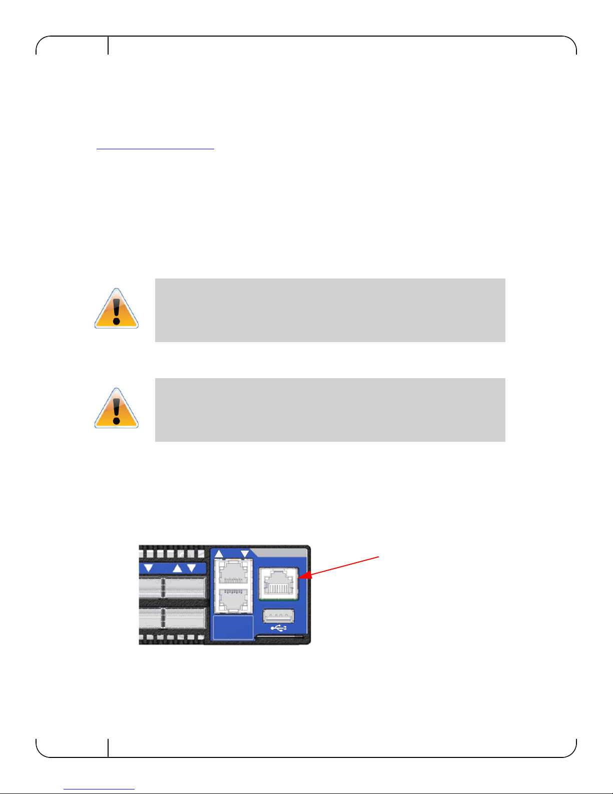
Connect the host PC to here
You will need the MLNX-OS package or Mellanox UFM™ to update firmware for this switch.
The MLNX-OS package can be downloaded from:
http://www.mellanox.com. => Products > Management Software > MLNX-OS.
The Mellanox UFM Management software is also an option to more closely manage your fabric,
switches and nodes.
The switch can be managed either remotely, or Out-of-Band using MLNX-OS.
4.1 Chassis Management Using the MLNX-OS™ Soft ware
The SX10XX switches come standard with a management software module for chassis management called Mellanox Operating System (MLNX-OS). MLNX-OS is installed on all SwitchX
based managed switch systems. MLNX-OS includes a CLI and chassis management software .
The Ethernet ports for remote management connect to Ethernet switches. These
switches must be configured to 100M/1G auto-negotiation.
Management and Tools OverviewRev 1.3
4.2 Configuring the Switch for the First Time
Unmanaged (Externally managed) switches do not get configured. The CONSOLE,
Ethernet, and USB connectors are not found on unmanaged switches. Instead there is
an I2C connector.
The port labelled CONSOLE must be connected to a local host PC. This must be used the first
time the switch is connected. This must be done before any remote management is available.
Hook up the supplied harness cable (HAR00028) from the connector labelled CONSOLE to the
DB9 connector of the local host PC.
Figure 34: Host Connection
See the “Installation Guide” of the SX10XX switches for full instructions regarding initial con-
figuration. See the “Configuring the Switch for the First Time” section of the “Installation
Guide”.
44
Mellanox Technologies
Page 45

SwitchX 36-Port QSFP 40Gb/s Ethernet System Hardware User Manual Rev 1.3
4.2.1 Starting a Remote Connection to the Switch
There are two ways to access the management CPU:
• Via the Ethernet connector for remote access:
•SSH
•Telnet
•Web
•SNMP
•XML
• Via KVM connections locally
For details on the SNMP commands and MIBs supported refer to the MLNX-OS Software Command Reference Guide.
4.2.2 Upgrading Software
Software and firmware updates are available from the Mellanox Support website. Copy the
update to a known location on a Remote server within the user’s LAN.
Use the CLI in order to perform Software upgrades. For further information please refer to the
MLNX-OS User Manual.
Be sure to read and follow all of the instructions regarding the updating of the software on your
switch system.
Mellanox Technologies
45
Page 46

5 Troubleshooting
As soon as a switch is plugged in make sure that the green power LEDs on the PS units are on.
Status LED and or Status Health LED
If either of these two LEDs is red unplug the switch and call your Mellanox representative.
Power supply unit:
If the LED on the PS unit is not lit or is red, check that the power cable is plugged into a working
outlet.
1. Check that the power cable has a voltage within the range of 100 - 240 volts AC.
2. Check that the air flow direction of the PS units are consistent with the Fan module air flow.
3. Remove and reinstall the power cable.
4. Remove and reinstall the PS unit.
The power LED for the switch shuts off:
1. Check that the there is adequate ventilation. Are the fan LEDs showing that the fans are all up
and running?
2. Make sure that there is nothing blocking the front or rear of the chassis an d that the fan mo d-
ules and ventilation holes are not blocked (especially dust over the holes).
TroubleshootingRev 1.3
3. If you find dust blocking the holes it is recommended to clean the fan unit and remove the
dust from the front and rear panels of the switch using a vacuum cleaner.
The green power LED for the fans does not come on:
1. Check that the Power LEDs are on.
2. Remove and reinstall the fan unit. Make sure the mating connector of the new unit is free of
any dirt and/or obstacles. See
Section 3.13, “Extracting and Inserting the Fan Unit,” on
page 40.
3. Check that the mating connector pins are not bent.
Caution: Do not run the switch if the System Status LED for the Fans is Red!
The link LED for the connector does not come on:
1. Check that both ends of the cable are connected.
2. Check that the locks on the ends are secured.
3. Make sure that the latest firmware version is installed on all of the HCA cards and the switch.
4. If media adapters are used, check that the all connections are good, tight, and secure.
The activity LED does not come on:
When running IB check that the Subnet Manager has been started.
The switch is off:
1. Unplug the switch.
2. Wait 5 minutes.
46
Mellanox Technologies
Page 47

SwitchX 36-Port QSFP 40Gb/s Ethernet System Hardware User Manual Rev 1.3
3. Plug in the switch.
4. If the switch does not come on, check the power supplies.
5. If the switch comes on, Use the MLNX-OS management CLI to determine the cause of the
Shutdown.
6. Check the temperature.
7. Check the Fan status.
The switch is not working and unresponsive:
1. Reset the switch.
If resetting the switch does not work:
2. Unplug the switch.
3. Wait 5 minutes.
4. Plug in the switch.
5. If the switch does not come on, check the power supplies.
6. If the switch comes on, use the MLNX-OS management CLI to determine the cause of the
shutdown.
The last software update did not succeed:
1. Connect the RS232 connector (CONSOLE) to a laptop.
2. Push the reset button on the switch or management module.
3. You will have ~ 5 seconds to stop the U-Boot by pressing Control-B.
4. Choose the image to upload. Only use image 1 or image 2.
U-Boot 2009.01-mlnx1.4 (May 12 2010 - 14:08:15)
CPU: AMCC PowerPC 460EX Rev. A at 1000 MHz (PLB=200, OPB=100,
EBC=100 MHz)
Security/Kasumi support
Bootstrap Option H - Boot ROM Location I2C (Addr 0x52)
Internal PCI arbiter disabled
32 kB I-Cache 32 kB D-Cache
Board: Mellanox PPC460EX Board
FDEF: No
I2C: ready
DRAM: 2 GB (ECC enabled, 400 MHz, CL3)
FLASH: 16 MB
NAND: 1024 MiB
PCI: Bus Dev VenId DevId Class Int
Mellanox Technologies
47
Page 48

PCIE0: link is not up.
PCIE1: successfully set as root-complex
01 00 15b3 bd34 0c06 00
Net: ppc_4xx_eth0, ppc_4xx_eth1
Hit Ctrl+B to stop autoboot: 0
Mellanox MLNX-OS
Boot Menu:
1. EFM_PPC_M460EX EFM_1.1.1000 2010-06-24 16:32:03 ppc
2. EFM_PPC_M460EX EFM_1.1.1200 2010-06-25 18 :00:03 ppc
3. U-Boot prompt
Choice:
5. Select the image to boot.
TroubleshootingRev 1.3
48
Mellanox Technologies
Page 49
SwitchX 36-Port QSFP 40Gb/s Ethernet System Hardware User Manual Rev 1.3
Appendix A: Specification
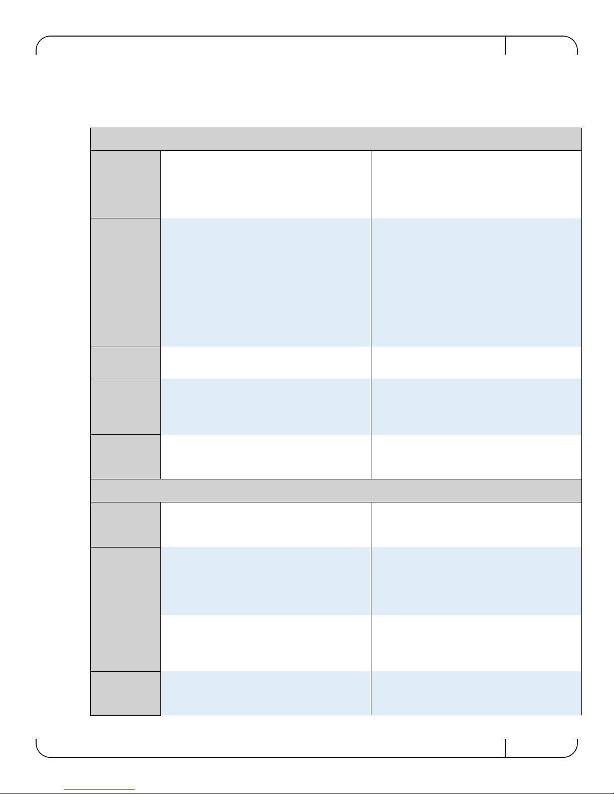
Table 11 - SX103[56]Specification Data
Physical
Size:
Size
SX103[56]B
(short)
1.716” (1U) H x 16.85” W x
16.8” D
43.6mm X 427.9mm X 428.9mm
SX1056S
(Standard i.e.
long)
1.716” (1U) H x 16.85” W
x24.75” D
43.6mm X 427.9mm X 628.9 mm
Weight /
Center of
Gravity
Mounting
SerDes Speeds /
Connector Types
Air Flow/
Heat dissipation
Input Voltage /
Management
CPU
Weight:
Short:
Standard:
Mounting:
SerDes Speeds:
Air Flow:
Input Voltage:
7.08kg 1 PS unit
7.82kg 2 PS units
8.02kg 1 PS unit
8.76kg 2 PS units
19” Rack mount
10, 20, or 40,Gb/s per port
62 CFM
Power and Environmental
100 - 240 VAC 50-60Hz
Center of Gravity:
Short:
1PS unit
2PS units
Standard:
1PS unit
2PS units
Connector
Types:
Heat dissipation:
Maximum
Management
CPU:
As measured from the Connector
side, left side bottom corner.
21.6mm X 193mm X 209.8mm
21.6mm X 214mm X 218.8mm
21.6mm X 201mm X 337mm
21.6mm X 214mm X 348mm
QSFP
Can use QSFP to SFP+ adapter
modules
798 BTUs/hr
PowerPC 460EX CPU
Power
Consumption: PS unit fan is always at 70%
Power numbers
Max@Max:
40GbE
Active Cables:
Passive cables:
Cable power /
Temperature
QSFP
224W – 6.2 W/port
119W – 3.3W/port
MAX 2.0W
TYP: 1.5W
Typ@Typ:
40GbE
Active Cables:
Passive cables:
Temperature:
Operating
Non-operating
Mellanox Technologies
182W – 5W/port
100W – 2.8W/port
0° to 45° Celsius
-40° to 70° Celsius
49
Page 50

Rev 1.3
Shock and
Vibration/
Humidity
Shock and
Vibration: ETSI EN 300 019-2-2: 1999-09
Humidity:
Operating 5% - 95% non-condensing
50
Mellanox Technologies
Page 51
SwitchX 36-Port QSFP 40Gb/s Ethernet System Hardware User Manual Rev 1.3
Protocol Support
Speed protocol \
QoS /
Management
Data Rate
Safety \
EMC
(Emissions)
Environmental /
Acoustic
Ethernet:
Auto-Negotiation of (40Gb/s,
10Gb/s, 1Gb/s)
Data Rate:
40Gb/s
Regulatory Compliance
Safety: US/Canada: cTUVus
EU: IEC60950
International: CB
Russia: GOST-R
Argentina: S-mark DoC
Environmental:
EU: IEC 60068-2-64: Random
Vibration
EU: IEC 60068-2-29: Shocks,
Type I / II
EU: IEC 60068-2-32: Fall Test
Management:
EMC
(Emissions):
Acoustic:
Managed using MLNX-OS
USA: FCC, Class A
Canada: ICES, Class A
EU: EN55022, Class A
EU: EN55024, Class A
EU: EN61000-3-2, Class A
EU: EN61000-3-3, Class A
Japan: VCCI, Class A
Australia / New-Zealand:
AS/NZS CISPR 22 class A
ISO 7779
ETS 300 753
Switching
Performance /
Capacity
Switching
Performance: Simultaneous wire-speed any port
Hot-Swappable:
Hot swapability /
Redundancy
1+1 Redundant:
A.1 Approved Cables
For a list of all approved cables see:
http://www.mellanox.com/related-docs/user_manuals/Mellanox_approved_cables.pdf
A.2 EMC Certifications
The list of approved certifications per switch in different regions of the world is located on the
Mellanox Website at:
http://www.mellanox.com/related-docs/user_manuals/Regulatory_and_Compliance_Guide.pdf
Scalability and Performance
Switching
Capacity: 2.88Tb/s
to any port
Reliability, Availability and Serviceability Features
Fan Module
Power Supplies
EMC statements are also in the Regulatory and Compliance Guide.
Mellanox Technologies
51
Page 52

Rev 1.3
A.3 China CCC Warning Statement
52
Mellanox Technologies
Page 53

SwitchX 36-Port QSFP 40Gb/s Ethernet System Hardware User Manual Rev 1.3
Appendix B: Thermal Threshold Definitions
There are three thermal threshold definitions for the SwitchX® switch device which impact the
overall switch system operation state: Warning, Critical and Emergency.
1. Warning – 100C
On managed systems only: When the SwitchX® device crosses the 100C threshold, a Warning
Threshold message will be issued by the MLNX-OS management SW, indicating to system
administration that the switch has crossed the Warning threshold.
Note that this temperature threshold does not require nor lead to any action by hardware (such as
switch shutdown).
2. Critical – 120C
When the SwitchX® device crosses this temperature, the firmware will automatically shut down
the device.
3. Emergency – 130C
In case the firmware fails to shut down the SwitchX® device upon crossing the Critical thresh-
old, the SwitchX® device will auto-shutdown upon crossing the Emergency (130C) threshold.
Mellanox Technologies
53
Page 54
Rev 1.3
Appendix C: Transferring the Power Cord
To use the rail kit to transfer the power cord from the connector side to the power side follow
these directions. Do you want to install power cords on both sides of the switch or only one side?
For each power cord you want to transfer:
1. Once you have decided which side of the switch will be next to the vertical support?
2. Make sure that you place the cord so that the correct end of the cord will be at the power side
of the switch. This will depend on which of the four mounting options you choose.
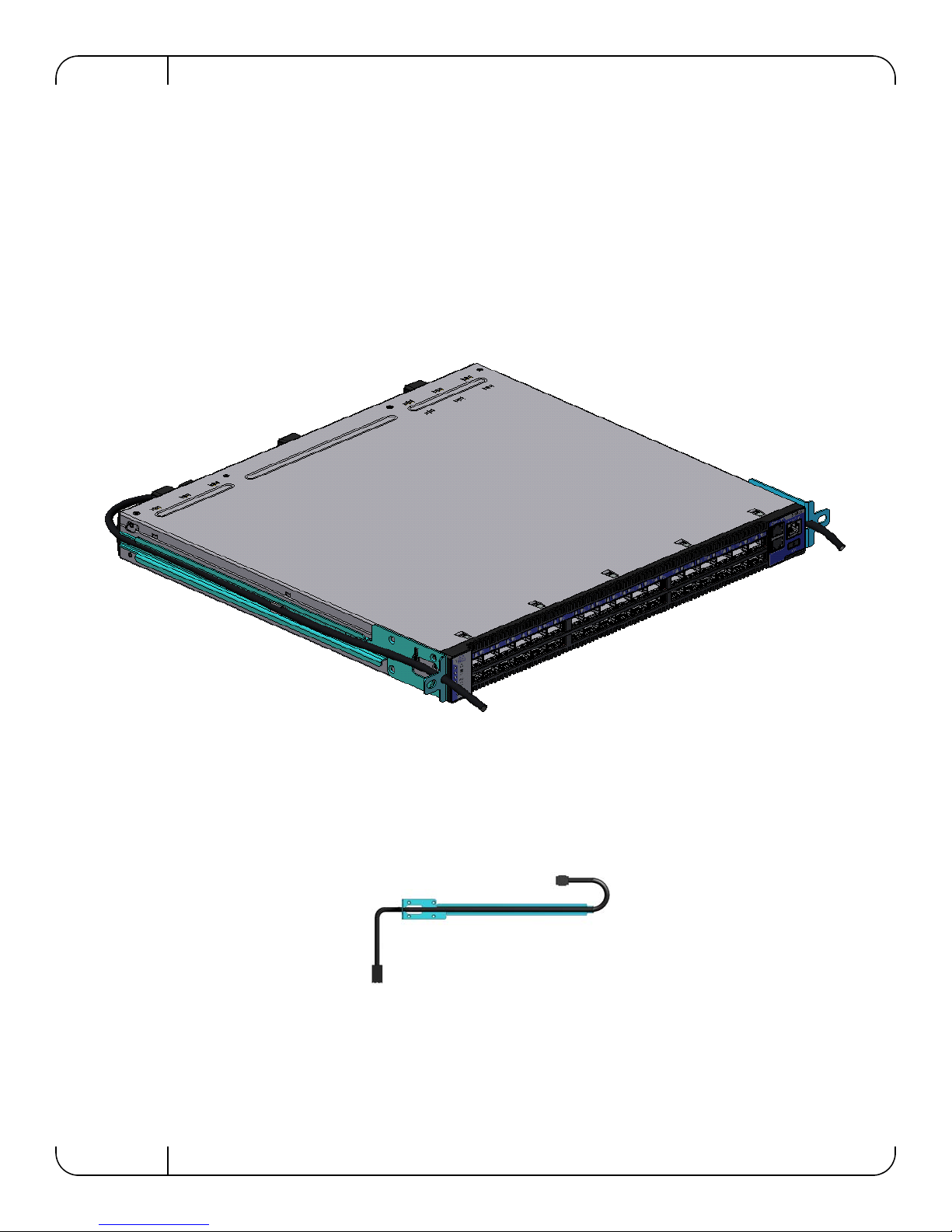
Figure 35: Transfer Power Cord
54
3. Put the power cord in the switch slide channel.
4. Push the cord end through the hole in the switch slide. Leave ~ 7” of cord hanging out from
the hole.
Figure 36: Put the Cord Through the Switch Slide Before Screwing it to the Switch
5. Screw the switch slides to the switch.
Mellanox Technologies
Page 55
SwitchX 36-Port QSFP 40Gb/s Ethernet System Hardware User Manual Rev 1.3
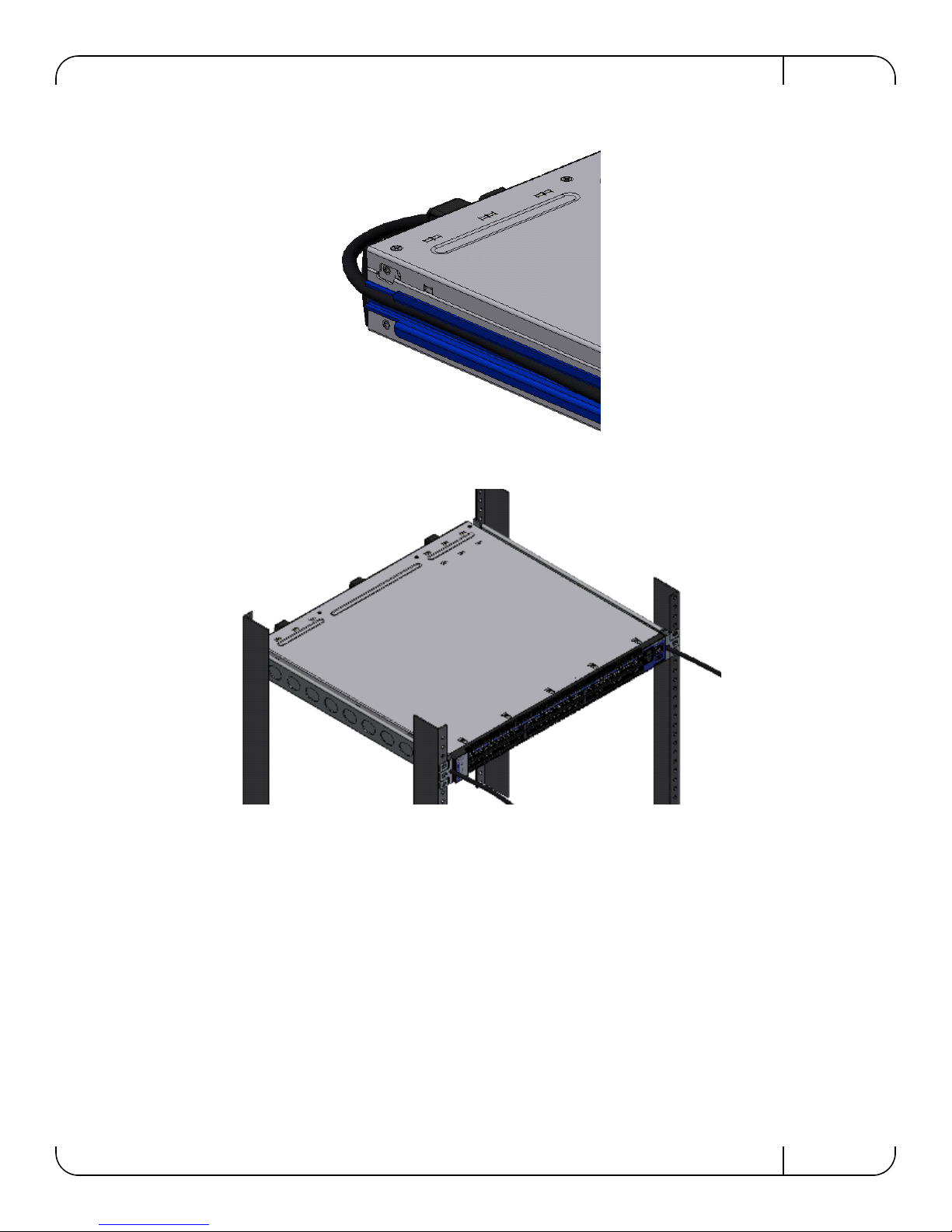
Figure 37: Screw the Switch Slide to the Switch
Figure 38: Transfer Power Cord Finished
6. Return to step 2 on page 22 and continue the installation.
Mellanox Technologies
55
Page 56
Rev 1.3
GND
Rx2n
GND
1
2
3
4
5
6
7
8
9
10
11
12
13
14
15
16
17
18
19
20
21
22
23
24
25
26
27
28
29
30
31
32
33
34
35
36
37
38
Rx1n
Rx2p
Rx1p
GND
GND
GND
GND
GND
GND
Tx2n
Tx1n
Tx2pTx1p
Tx4n
Tx3n
Tx4p
Tx3p
GND
GND
Rx4n
Rx3n
Rx4p
Rx3p
GND
GND
SDA
SCL
Vcc Rx
ResetL
ModSelLLPMode
Vcc1
VccTx
IntL
ModPrsL
J3 and J6
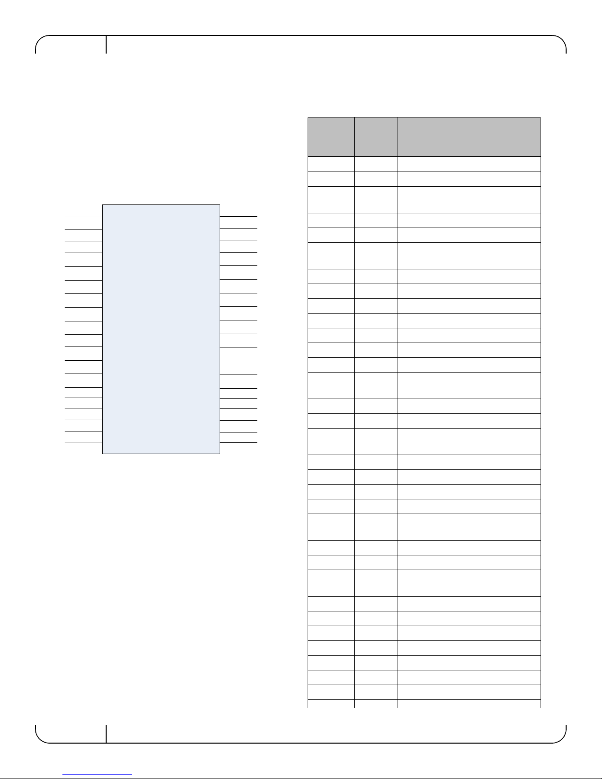
Table 12 - InfiniBand QSFP Connector Pinout
Connector
Pin
Number
Connecto
r Pin
Name
Signal Description
1 GND Ground
2 Tx2n Transmitter Inverted Data Input
3
Tx2p Transmitter Non-Inverted Data
Input
4 GND Ground
5 Tx4n Transmitter Inverted Data Input
6
Tx4p Transmitter Non-Inverted Data
Input
7 GND Ground
8 ModSelL Module Select
9 ResetL Module Reset
10 Vcc Rx +3.3 V Power supply receiver
11 SCL 2-wire serial interface clock
12 SDA 2-wire serial interface data
13 GND Ground
14
Rx3p Receiver Non-Inverted Data Out-
put
15 Rx3n Receiver Inverted Data Output
16 GND Ground
17
Rx1p Receiver Non-Inverted Data Out-
put
18 Rx1n Receiver Inverted Data Output
19 GND Ground
20 GND Ground
21 Rx2n Receiver Inverted Data Output 3
22
Rx2p Receiver Non-Inverted Data Out-
put 3
23 GND Ground
24 Rx4n Receiver Inverted Data Output 3
25
Rx4p Receiver Non-Inverted Data Out-
put 3
26 GND Ground
27 ModPrsL Module Present
28 IntL Interrupt
29 Vcc Tx +3.3 V Power supply transmitter
30 Vcc 1 + 3.3 V Power Supply
31 LPMode Low Power Mode
32 GND Ground
Appendix D: QSFP Interface
56
Mellanox Technologies
Page 57
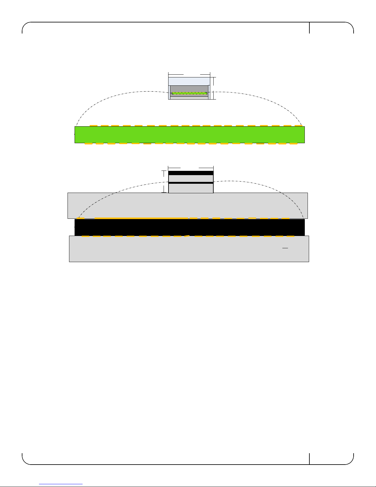
SwitchX 36-Port QSFP 40Gb/s Ethernet System Hardware User Manual Rev 1.3
18.35
8.50
Top
ResetL
SDA
SCL
ModSelL
RX3p
TX2n
GND
VccRx
1
2
3
4
5
6
7
8
9
1
0
1
2
3
4
5
6
7
8
9
TX2p
GND
TX4n
TX4p
GND
1
1
1
1
1
1
1
1
1
1
20
GND
GND
GND
RX3n
RX1p
RX1n
30
1
2
3
4
5
6
7
8
9
2
2
2
2
2
2
2
2
2
1
2
3
4
5
6
7
8
3
3
3
3
3
3
3
3
RX4p
GND
GND
GND
RX4n
RX2p
RX2n
TX1n
GND
TX1p
GND
TX3n
TX3p
GND
IntL
ModPrsL
VccTx
Vcc1
LPMode
18.35
8.50
Top
ResetL
SDA
SCL
ModSelL
RX3p
TX2n
GND
VccRx
1
2
3
4
5
6
7
8
9
1
0
1
2
3
4
5
6
7
8
9
TX2p
GND
TX4n
TX4p
GND
1
1
1
1
1
1
1
1
1
1
20
GND
GND
GND
RX3n
RX1p
RX1n
30
RX4p
GND
GND
GND
RX4n
RX2p
RX2n
TX1n
GND
TX1p
GND
TX3n
TX3p
GND
IntL
ModPrsL
VccTx
Vcc1
LPMode
1
2
3
4
5
6
7
8
3
3
3
3
3
3
3
3
1
2
3
4
5
6
7
8
9
2
2
2
2
2
2
2
2
2
View into Front of Cage
View into Rear of
Connector
Figure 39: QSFP Connector Male and Female Views
Mellanox Technologies
57
Page 58
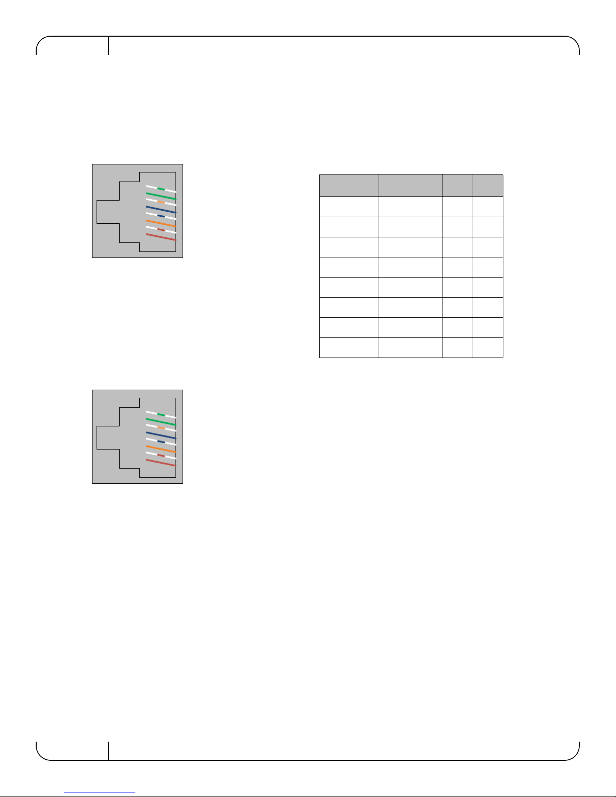
Rev 1.3
TXD+
TXDRXD+
GND
GND
RXDGND
GND
RJ45_RTS#
RJ45_DTR#
RJ45_TXD
GND
GND
RJ45_RXD
GND
GND
J34
Pin 1
Pin 8
Looking into the Socket
CONSOLE
TXD+
TXDRXD+
GND
GND
RXDGND
GND
RJ45_SDA
GND
GND
GND
GND
RJ45_SCL
GND
GND
J34
Pin 1
Pin 8
Looking into the Socket
I
2
C
Table 13 - RJ-45 Pinout
Connection Signal Pin# Color
TXD+ RJ-45_RTS# 1 G/W
TXD- RJ-45_DTR# 2 G
RXD+ RJ-45_TXD 3 O/W
GND GND 4 Bl
GND GND 5 Bl/W
RXD- RJ-45_RXD 6 O
GND GND 7 Br/W
GND GND 8 Br
Appendix E: RJ-45 CONSOLE and Ethernet interfaces
The RJ-45 CONSOLE and Ethernet interfaces uses the EIA 568A standard wiring color coding.
58
Mellanox Technologies
Page 59
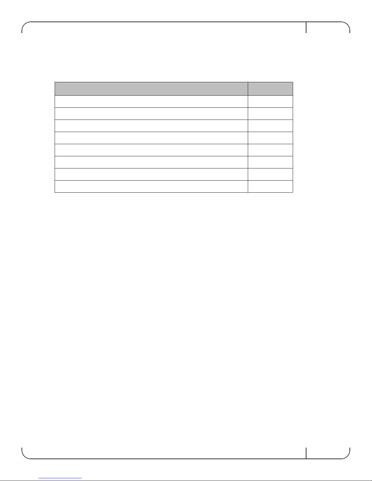
SwitchX 36-Port QSFP 40Gb/s Ethernet System Hardware User Manual Rev 1.3
Appendix F: Replacement Parts Ordering Numbers
Table 14 - Replacement Parts Ordering Numbers
Part Description OPN
I2C DB9 or RJ-45 to USB Adapter MTUSB-1
Fan module with power supply side to connector side air flow MSX60-FF
Fan module with connector side to power supply side air flow MSX60-FR
300W Power Supply w/ Power Supply Side to Connector side air flow MSX60-PF
300W Power Supply w/ Connector side to Power Supply side air flow MSX60-PR
Power cord Ty pe C13-C14 ACC000500
Installation Kit for short switches in racks 40-60 cm deep MSX60-BKIT
Installation Kit for short or standard switches in racks 60-80 cm deep MSX60-SKIT
Mellanox Technologies
59
Page 60
Rev 1.3
Appendix G: Avertissements de sécurité d’installation
(French)
1. Instructions d’installation
Lisez toutes les instructions d’installation avant de brancher le matériel à la source
d’alimentation électrique.
2. Température excessive
Ce matériel ne doit pas fonctionner dans une zone avec une température ambiante
dépassant le maximum recommandé de 45°C (113°F). Un flux d’air de 200LFM à
cette température ambiante maximale est nécessaire. En outre, pour garantir un bon
écoulement de l’air, laissez au moins 8 cm (3 pouces) d’espace libre autour des ouver
tures de ventilation.
3. Empilage du châssis
-
Le châssis ne doit pas être empilé sur un autre matériel. Si le châssis tombe, il peut provoquer des blessures corporelles et des dégradations de biens.
4. Connection d'Alimentation electrique excedentaire -dangers électriques
Ce produit comporte un couvercle transparent sur l’espace pour l’alimentation élec-
trique redondante.
Ne pas faire fonctionner le produit si le couvercle transparent n’est pas solidement
fixé ou s’il est enlevé.
5. Système de fusible neutre/à double pôle
Avertissement: Système de fusible neutre/à double pôle. Veuillez debrancher tous les
cordons d'alimentation avant d'ouvrir le boitier de ce produit ou de toucher un de ses
composants internes.
6. Orages – dangers électriques
Pendant un orage, il ne faut pas utiliser le matériel et il ne faut pas brancher ou
débrancher les câbles.
60
Mellanox Technologies
Page 61
SwitchX 36-Port QSFP 40Gb/s Ethernet System Hardware User Manual Rev 1.3
7. Branchement/débranchement des câbles en cuivre
Les câbles InfiniBand en cuivre sont lourds et ne sont pas flexibles, il faut donc faire
très attention en les branchant et en les débranchant des connecteurs. Consultez le fab
ricant des câbles pour connaître les mises en garde et les instructions spéciales.
-
8. Risque de choc et de danger
Risque de choc et de danger
e’lectriques. Le de’branchment d’une seule alimentation stabilise’e ne de’branch uniquement qu’un module “Alimentation Stabilise’e”. Pour isoler completement le module en
cause, Il faut de’brancher toutes les alimentations stabilise’es
Risk of electric shock and energy hazard.
The PSUs are all independent.
Disconnect all power supplies to ensure a powered down state inside of the switch plat-
form.
9. Montage et entretien sur baie
Lorsque ce produit est monté ou entretenu sur baie, il faut prendre des précautions spéciales pour s’assurer que le système reste stable. En général, il faut remplir la baie avec
du matériel de bas en haut.
10. Fuite>3.5mA Leakage >3.5mA
« ATTENTION – La connexion à la terre des forts courants de fuite est essentielle
avant le branchement de l’alimentation. »
Avant de brancher l’appareil à la conduite d’alimentation, les vis de protection à la
terre du terminal de l’appareil doivent être appliquées à l’installation de protection à la
T erre du bâtiment.
11. Forts Courants de Fuite High Leakage Current
Attention: Forts courants de fuite. Il est essentiel de relier a la terre avant de brancher
l'alimentation.
12. Ajouter une information de connexion à la masse Connect a Valid Ground to this Device
Avant de brancher l’appareil à la conduite d’alimentation, les vis de protection à la
terre du terminal de l’appareil doivent être appliquées à l’installation de protection à la
T erre du bâtiment.
Mellanox Technologies
61
Page 62
Rev 1.3
13. Installation du matériel
Ce matériel ne doit être installé, remplacé ou entretenu que par du personnel formé et
qualifié.
14. Elimination du matériel
L’élimination de ce matériel doit s’effectuer dans le respect de toutes les législations et
réglementations nationales en vigueur.
15. Codes électriques locaux et nationaux
Ce matériel doit être installé dans le respect des codes électriques locaux et nationaux.
16. Codes d’installation
L ’appareil doit être installé selon l’ancienne version des codes électriques nationaux du
pays. Pour l’Amérique du Nord, l’équipement doit être installé conformément aux
spécifications du Code Electrique National Américain et du Code Electrique Canadien.
17. Interconnexion des unites
Les câbles de branchement à l’unité RS232 et les interfaces Ethernet doivent être certifiés UL de type DP-1 ou DP-2. (Note - lorsqu’il existe dans un circuit non LPS)
Protection contre la surintensité : Un appareil de protection répertorié facilement
accessible contre la surintensité du circuit de branchement et calibré à 20A doit être
incorporé dans le câblage électrique du bâtiment.
18. Exposition au rayonnement grave
Mise en garde – l'utilisation de commandes ou de réglages ou l'exécution de procédures autres que ce qui est spécifié dans les présentes peut engendrer une exposition au
rayonnement grave.
PRODUIT LASER DE CLASSE 1 » et références aux normes laser les plus récentes
CEI 60 825-1:1993 + A1:1997 + A2:2001 et NE 60825-1:1994+A1:1996+ A2:2001
62
Mellanox Technologies
Page 63
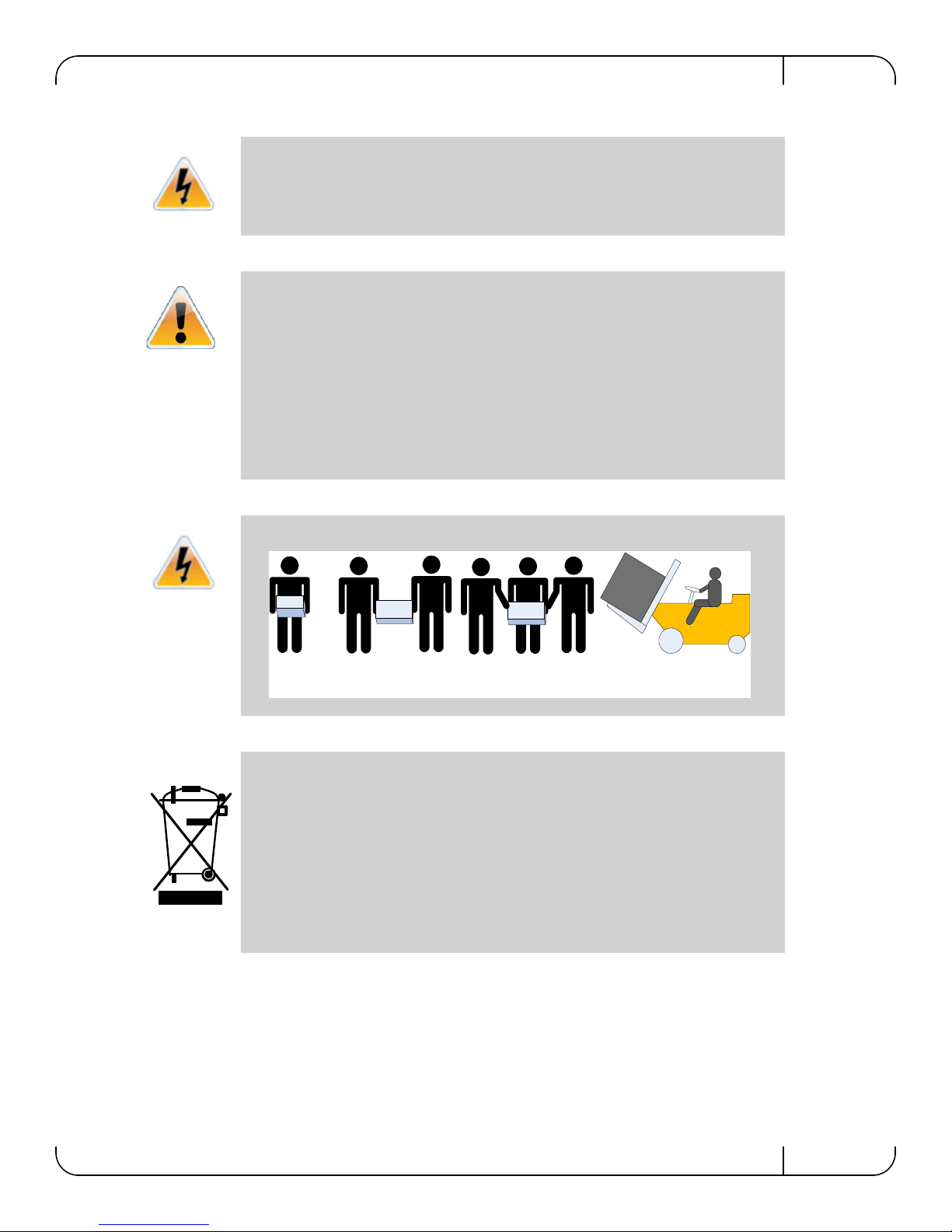
SwitchX 36-Port QSFP 40Gb/s Ethernet System Hardware User Manual Rev 1.3
<40 lbs
<18 kgs
40 - 70 lbs
18 - 32 kgs
70 - 121 lbs
32 - 55 kgs
>121 lbs
>55 kgs
19. S’assurer que les enceintes sont appropriées
Des enceintes électriques, mécaniques et incendie adaptées doivent être fournies par le
fabricant du produit final ou par l’utilisateur final.
20. Cordons électriques CA homologués UL
Pour les prises électriques en Amérique du Nord, choisissez un cordon électrique
homologué UL et certifié CSA
à 3 conducteurs, [18 AWG], terminé par une fiche moulée, d’une tension nominale de
125 V, [15 A], avec une longueur minimale de 1,5 m [6 pieds] et d’une longueur maxi
-
male de 4,5 m [18 pieds]
Pour les prises électriques en Europe, choisissez un cordon électrique harmonisé inter-
nationalement et marqué "<HAR>",
à 3 conducteurs, d’un diamètre de fil minimum de 0,75 mm2, d’une tension nominale
de 300 V, avec une gaine isolée en PVC. Le cordon doit avoir une fiche moulée d’une
tension nominale de 250 V et d’une intensité nominale de 10 A.
21.
22. Conformément à la Directive WEEE
Conformément à la Directive WEEE 2002/96/EC, les déchets d'équipements électriques et électroniques (EEE) doivent être triés et ne peuvent être éliminés avec les
déchets ménagers.
Veuillez disposer de ce produit et de tous ses composants de man ière resp onsable et
respectueuse de l’environnement.
Mellanox Technologies
63
Page 64
Rev 1.3
Appendix H: Installation - Sicherheitshinweise (German)
1. Installationsanleitungen
Lesen Sie alle Installationsanleitungen, bevor Sie das Gerät an die Stromversorgung
anschließen.
2. Übertemperatur
Dieses Gerät sollte nicht in einem Bereich mit einer Umgebungstemperatur über der
maximal empfohlenen Temperatur von 45°C (1 13°F) betrieben werden. Es ist ein Luft
strom von 200 LFM bei maximaler Umgebungstemperatur erforderli ch. Außerdem
sollten mindestens 8 cm (3 in.) Freiraum um die Belüftungsöffnungen sein, um einen
einwandfreien Luftstrom zu gewährleisten.
3. Stapeln des Chassis
Das Chassis sollte nicht auf andere Geräte gestapelt werden. Wenn das Chassis herunterfällt, kann es zu Verletzungen und Beschädigungen an Geräten führen.
-
4. Redundanter Stromversorgungsanschluss - Elektrische Gefahr
Dieses Produkt verfügt über eine Abdeckung über dem Bereich für die redundante
Stromversorgung. Betreiben Sie das Produkt nicht, wenn diese Abdeckung nicht sicher
festsitzt oder entfernt wurde.
5. Bei Gewitter - Elektrische Gefahr
Arbeiten Sie während eines Gewitters und Blitzschlag nicht am Gerät, schließen Sie
keine Kabel an oder ab.
6. Anschließen/Trennen von Kupferkabel
Kupferkabel sind schwer und nicht flexible. Deshalb müssen sie vorsichtig an die
Anschlüsse angebracht bzw. davon getrennt werden. Lesen Sie die speziellen Warnun
gen und Anleitungen des Kabelherstellers.
7. Gafahr des elektrischen Schocks.
-
Gafahr des elektrischen Schocks. Entferrnen des Netzsteckers elnes Netzteils spannungsfrei. Um alle Einhieten spannungsfrei zu machen sind die Netzstecker aller Netzteile zu
entfernen
64
Mellanox Technologies
Page 65
SwitchX 36-Port QSFP 40Gb/s Ethernet System Hardware User Manual Rev 1.3
Risk of electric shock and energy hazard.
The PSUs are all independent.
Disconnect all power supplies to ensure a powered down state inside of the switch plat-
form.
8. Rack-Montage und Wartung
Wenn dieses Produkt in einem Rack montiert oder gewartet wird, sind besondere Vorsichtsmaßnahmen zu ergreifen, um die Stabilität des Systems zu gewährleisten. Im
Allgemeinen sollten Sie das Gestell von unten nach oben mit Geräten füllen.
9. Geräteinstallation
Diese Gerät sollte nur von geschultem und qualifiziertem Personal installiert, ausgetauscht oder gewartet werden.
10. Geräteentsorgung
Die Entsorgung dieses Geräts sollte unter Beachtung aller nationalen Gesetze Bestimmungen erfolgen.
11. Regionale und nationale elektrische Bestimmungen
Dieses Gerät sollte unter Beachtung der regionalen und nationalen elektrischen
Bestimmungen installiert werden.
12. Richtigen Schutz sicherstellen
Geeigneter elekrischer, mechanischer und Feuerschutz sind vom
Hersteller des Endprodukts oder dem Endbenutzer bereitzustellen.
13. Strahlenkontakt
Achtung – Nutzung von Steuerungen oder Einstellungen oder Ausführung von Prozeduren, die hier nicht spezifiziert sind, kann zu gefährlichem Strahlenkontakt führen..
Klasse 1 Laserprodukt und Referenzen zu den aktuellsten Lasterstandards :
ICE 60 825-1:1993 + A1:1997 + A2:2001 und EN 60825-1:1994+A1:1996+ A2:2001
Mellanox Technologies
65
Page 66
Rev 1.3
14. UL-und CSA Certified Netzkabel
Für Nordamerika Stromanschluss, wählen Sie ein Netzkabel, das UL-und CSA Certified
3 - Leiter, [18 AWG], mit einem angespritztem Stecker bewertet bei 125 V, [15], mit
einer Mindestlänge von 1,5 m [Six Feet] aber nicht mehr als 4,5 m.
Für die europäischen Zusammenhang, wählen Sie ein Netzkabel, das international
harmonisiert und der Aufschrift "<HAR>",
3 - Leiter, mindestens 0,75 mm2 Draht, bewertet mit 300 V, mit einem PVC-Mantel
isoliert. Das Kabel muss eine angespritztem Stecker bewertet bei 250 V, 10 A. "
15. Ableitstrom> 3.5mA LEAKAGE >3.5mA
WARNUNG: Hohe Ableitstro m; Earth Verbindung, bevor Sie die Verbindung von
wesentlicher Bedeutung werden.
16. Add GND Verbindung Informationen
Bevor Sie dieses Gerät an das Stromnetz, die Schutzerde Terminal Schrauben dieses
Gerät muss an den Schutzleiter in der Gebäudeinstallation.
17. Installation Codes
Dieses Gerät muss installiert sein, entsprechend auf die neueste Version des Landes
National Electrical Code. Für Nordamerika, müssen in Übereinstimmung mit den gel
tenden Vorschriften in der US-amerikanischen National Electrical Code und dem
Canadian Electrical Code.
18. Zusammenschaltung von EINHEITEN
Kabel für den Anschluss an das Gerät RS232-und Ethernet-Schnittstellen müssen UL
zertifiziert Typ DP-1 oder DP-2. (Hinweis-, wenn nicht mit Wohnsitz in LPS-Schal
tung)
Überstromschutz: Eine leicht zugängliche Auflistung Abzweigleitung ÜberstromSchutzeinrichtung 20 A bewertet werden müssen in dem Gebäude Verkabelung.
19. Zweipolige bzw. Neutralleiter-Sicherung im Netzteil
Achtung:
Zweipolige bzw. Neutralleiter-Sicherung im Netzteil. Netzstecker ziehen, um sicher-
zustellen, daß keine Spannung am Gerät anliegt. Entfernen Sie alle Netzkabel vor dem
Öffnen der Abdeckung dieses Produkts oder dem Berühren der Innenteile.
-
-
66
Mellanox Technologies
Page 67
SwitchX 36-Port QSFP 40Gb/s Ethernet System Hardware User Manual Rev 1.3
<40 lbs
<18 kgs
40 - 70 lbs
18 - 32 kgs
70 - 121 lbs
32 - 55 kgs
>121 lbs
>55 kgs
<40 lbs
<18 kgs
40 - 70 lbs
18 - 32 kgs
70 - 121 lbs
32 - 55 kgs
>121 lbs
>55 kgs
20. Bodily Injury Due to Weight
Use enough people to safely lift this product.
Mellanox Technologies
67
Page 68
Rev 1.3
<40 lbs
<18 kgs
40 - 70 lbs
18 - 32 kgs
70 - 121 lbs
32 - 55 kgs
>121 lbs
>55 kgs
Appendix I: Advertencias de seguridad para la insta-
lación (Spanish)
1. Instrucciones de instalación
Antes de conectar el equipo a la fuente de alimentación, leer todas las instrucciones de
instalación.
2. Lesión corporal por peso
3. Lesión corporal por peso
This equipment is very heavy and should be moved using a mechanical lift to avoid
injuries.
4. Sobrecalentamiento
No se debe utilizar el equipo en un área con una temperatura ambiente superior a la
máxima recomendada: 45°C. Además, para garantizar una circulación de aire adec
uada, se debe dejar como mínimo un espacio de 8 cm (3 pulgadas) alrededor de las
aberturas de ventilación.
5. Apilamiento del chasis
Los chasis no se deben apilar sobre otros equipos. La caída del chasis podría causar
lesiones corporales, así como daños al equipo.
6. Dos fusibles, uno en el polo y otro en el neutro
-
Dos fusibles, uno en el polo y otro en el neutro. Quitar los cables de corriente antes de
abrir la tapa de este producto o tocar cualquier componente interno.
68
Mellanox Technologies
Page 69
SwitchX 36-Port QSFP 40Gb/s Ethernet System Hardware User Manual Rev 1.3
7. Cuando hay rayos: peligro de descarga eléctrica
No utilizar el equipo ni conectar o desconectar cables durante períodos de actividad de
rayos.
8. Conexión y desconexión del cable Copper
Dado que los cables de cobre son pesados y no son flexibles, su conexión a los conectores y su desconexión se deben efectuar con mucho cuidado. Para ver advertencias o
instrucciones especiales, consultar al fabricante del cable.
9. Montaje y mantenimiento de bastidores
Al instalar o realizar el mantenimiento de este aparato en un bastidor, es preciso adoptar precauciones especiales para garantizar que el sistema se mantenga estable. En general, en un bastidor, los equipos se deben instalar comenzando desde abajo hacia
arriba.
10. Instalación de equipos
La instalación, el reemplazo y el mantenimiento de este equipo estarán a cargo únicamente de personal capacitado y competente.
11. Asegurar confinamientos adecuados
El fabricante del producto final o el usuario final deberán suministrar
un confinamiento adecuado para componentes eléctricos y mecánicos y contra incendio.
12. Eliminación de equipos
La eliminación definitiva de este equipo se debe efectuar conforme a todas las leyes y
reglamentaciones nacionales.
13. Códigos eléctricos locales y nacionales
Este equipo se debe instalar conforme a los códigos eléctricos locales y nacionales.
Mellanox Technologies
69
Page 70
Rev 1.3
14. Cable de alimentación homologado por UL y con certificación CSA
En conexiones de América del Norte, seleccionar un cable de alimentación
homologado por UL y con certificación CSA de tres conductores, [16 AWG], termi
nado en un enchufe moldeado con capuchón de 125 voltios nominal, [13 A], con una
longitud mínima de 1,5 metros, pero no más de 4,5 metros.
En conexiones europeas, seleccionar un cable de alimentación armonizado
internacionalmente y marcado "<HAR>", de tres conductores, hilo de 1,0 mm2 como
mínimo, 300 voltios nominal, con cobertura protectora aislante de PVC. El cable debe
tener un enchufe moldeado con capuchón de 250 voltios nominal, 10 A.
15. Añadir conexión a tierra
Antes de conectar el dispositivo a la línea de alimentación, los tornillos del terminal de
la puesta a tierra de protección del dispositivo se deben conectar a la puesta a tierra de
protección de la instalación del edificio.
(Información de conexión a tierra):
La instalación del edificio deberá prover un medio para la conexión con la puesta a
tierra de protección y un técnico de servicio deberá conectar permanentemente el
equipo a dicho medio de conexión.
Un TÉCNICO DE SERVICIO comprobará si la toma eléctrica de la que se suministrará corriente al equipo provee una conexión con la puesta a tierra de protección del
edificio. De no ser así, el TÉCNICO DE SERVICIO se encargará de instalar un CON
DUCTOR DE CONEXIÓN A TIERRA DE PROTECCIÓN, del terminal de puesta a
tierra de protección separado al conductor de tierra de protección del edificio. El
equipo se instalará en un área donde haya conexión equipotencial, como por ejemplo,
un centro de telecomunicaciones o una sala de computadoras dedicada.
-
-
16. Códigos de instalación
Este dispositivo se debe instalar conforme a la versión más reciente de los códigos
eléctricos nacionales del país en cuestión. En América del Norte, el equipo se debe
instalar de acuerdo con las disposiciones vigentes del Código Eléctrico Nacional de los
EE.UU. y del Código Eléctrico de Canadá.
17. Directiva sobre RAEE
Conforme a la Directiva 2002/96/CE sobre RAEE, todos los residuos de equipos eléctricos y electrónicos (EEE) se deben recolectar por separado y no se deben eliminar
junto con residuos domésticos.
Al deshacerse de este producto y de todas sus partes, hágalo de una manera responsable y respetuosa con el medio ambiente.
70
Mellanox Technologies
 Loading...