

Page 1

Exported on Apr/20/2020 07:09 PM
https://docs.mellanox.com/x/Cw1p
Mellanox Technologies
Mellanox Spectrum® 1U Switch
Systems Hardware User Manual
10/25/40/50/100GbE Open Ethernet Switch Systems Models: SN2700, SN2740, SN2410, SN2100, SN2010
Page 2

2
Mellanox Technologies
NOTE:
THIS HARDWARE, SOFTWARE OR TEST SUITE PRODUCT (“PRODUCT(S)”) AND ITS RELATED DOCUMENTATION
ARE PROVIDED BY MELLANOX TECHNOLOGIES “AS-IS” WITH ALL FAULTS OF ANY KIND AND SOLELY FOR THE
PURPOSE OF AIDING THE CUSTOMER IN TESTING APPLICATIONS THAT USE THE PRODUCTS IN DESIGNATED
SOLUTIONS. THE CUSTOMER'S MANUFACTURING TEST ENVIRONMENT HAS NOT MET THE STANDARDS SET BY
MELLANOX TECHNOLOGIES TO FULLY QUALIFY THE PRODUCT(S) AND/OR THE SYSTEM USING IT. THEREFORE,
MELLANOX TECHNOLOGIES CANNOT AND DOES NOT GUARANTEE OR WARRANT THAT THE PRODUCTS WILL
OPERATE WITH THE HIGHEST QUALITY. ANY EXPRESS OR IMPLIED WARRANTIES, INCLUDING, BUT NOT LIMITED
TO, THE IMPLIED WARRANTIES OF MERCHANTABILITY, FITNESS FOR A PARTICULAR PURPOSE AND
NONINFRINGEMENT ARE DISCLAIMED. IN NO EVENT SHALL MELLANOX BE LIABLE TO CUSTOMER OR ANY
THIRD PARTIES FOR ANY DIRECT, INDIRECT, SPECIAL, EXEMPLARY, OR CONSEQUENTIAL DAMAGES OF ANY
KIND (INCLUDING, BUT NOT LIMITED TO, PAYMENT FOR PROCUREMENT OF SUBSTITUTE GOODS OR SERVICES;
LOSS OF USE, DATA, OR PROFITS; OR BUSINESS INTERRUPTION) HOWEVER CAUSED AND ON ANY THEORY OF
LIABILITY, WHETHER IN CONTRACT, STRICT LIABILITY, OR TORT (INCLUDING NEGLIGENCE OR OTHERWISE)
ARISING IN ANY WAY FROM THE USE OF THE PRODUCT(S) AND RELATED DOCUMENTATION EVEN IF ADVISED OF
THE POSSIBILITY OF SUCH DAMAGE.
Mellanox Technologies
350 Oakmead Parkway Suite 100
Sunnyvale, CA 94085, U.S.A.
www.mellanox.com
Tel: (408) 970-3400
Fax: (408) 970-3403
© Copyright 2020. Mellanox Technologies Ltd. All Rights Reserved.
Mellanox® and the Mellanox logo are registered trademarks of Mellanox Technologies, Ltd.
Additional trademarks used in this document are listed under http://www.mellanox.com/page/trademarks.
All other trademarks are property of their respective owners.
Page 3

3
Mellanox Technologies
Table of Contents
1 Ordering Information ............................................................................................................................................... 7
1.1 SN2700 Ordering Part Numbers ........................................................................................................................7
1.2 SN2410 Ordering Part Numbers ........................................................................................................................7
1.3 SN2100 Ordering Part Numbers ........................................................................................................................8
1.4 SN2010 Ordering Part Numbers ........................................................................................................................9
2 Introduction............................................................................................................................................................ 10
2.1 Speed and Switching Capabilities .................................................................................................................... 11
2.2 Management Interfaces, PSUs and Fans ........................................................................................................12
2.3 Features ...........................................................................................................................................................12
2.4 Certifications..................................................................................................................................................... 12
3 Installation ............................................................................................................................................................. 13
3.1 System Installation and Initialization ................................................................................................................13
3.2 Safety Warnings ............................................................................................................................................... 13
3.3 Air Flow ............................................................................................................................................................16
3.4 Package Contents ............................................................................................................................................ 17
3.5 19” System Mounting Options .......................................................................................................................... 17
3.6 SN2700 Static Rail Kit ...................................................................................................................................... 17
3.6.1 Removing the System from the Rack......................................................................................................... 21
3.7 SN2700 Telescopic Rail Kit ..............................................................................................................................21
3.7.1 Removing the System from the Rack......................................................................................................... 24
3.8 SN2740/SN2410 Static Rail Kit ........................................................................................................................ 25
3.9 SN2100/SN2010 Side by Side Mounting Rail Kit.............................................................................................27
3.10 SN2100/SN2010 Static Single Switch Rail Kit .................................................................................................31
3.11 Cable Installation..............................................................................................................................................33
3.11.1 Splitter (Breakout) Cables and Adapters.................................................................................................... 35
3.11.1.1 Using Splitter (Breakout) Cables with Mellanox Onyx (MLNX-OS)....................................................... 35
3.11.1.2 Using Splitter (Breakout) Cables with Cumulus Linux........................................................................... 35
3.11.1.3 SN2700 and SN2740 Splitting Options ................................................................................................. 35
3.11.1.4 SN2410 Splitting Options ...................................................................................................................... 36
3.11.1.5 SN2100 Splitting Options ...................................................................................................................... 36
3.11.1.6 SN2010 Splitting Options ..................................................................................................................... 36
3.12 Initial Power On ................................................................................................................................................ 37
3.13 System Bring-Up ..............................................................................................................................................38
3.13.1 Configuring Network Attributes Using Mellanox Onyx (MLNX-OS)............................................................ 38
3.13.1.1 Manual Host Configuration....................................................................................................................38
3.13.1.2 Disable Dynamic Host Configuration Protocol (DHCP)......................................................................... 41
Page 4

4
Mellanox Technologies
3.13.1.3 Remote Connection with Mellanox Onyx (MLNX-OS) .......................................................................... 42
3.13.2 Configuring Network Attributes Using Cumulus Linux................................................................................ 42
3.13.2.1 Remote Connection with Cumulus Linux ..............................................................................................42
3.14 FRU Replacements .......................................................................................................................................... 42
3.14.1 Power Supply ............................................................................................................................................. 42
3.14.2 Fans ........................................................................................................................................................... 43
4 Interfaces............................................................................................................................................................... 45
4.1 Data Interfaces ................................................................................................................................................. 45
4.1.1 Supported Passive Cables in SN2010bM .................................................................................................. 46
4.2 Speed ............................................................................................................................................................... 46
4.3 RS232 (Console)..............................................................................................................................................46
4.4 Management ....................................................................................................................................................46
4.5 USB ..................................................................................................................................................................47
4.6 Reset Button..................................................................................................................................................... 47
4.7 Status and Port LEDs.......................................................................................................................................47
4.8 LED Notifications..............................................................................................................................................47
4.8.1 System Status LED .................................................................................................................................... 48
4.8.2 Fan Status LED .......................................................................................................................................... 50
4.8.3 Power Supply Status LEDs ........................................................................................................................ 51
4.8.4 Unit Identification LED................................................................................................................................ 53
4.8.5 Bad Port LED ............................................................................................................................................. 53
4.8.6 Port LEDs ................................................................................................................................................... 54
4.9 Inventory Information........................................................................................................................................55
5 Software Management .......................................................................................................................................... 57
5.1 Upgrading Software..........................................................................................................................................57
5.1.1 Mellanox Onyx (MLNX-OS) Software Upgrade.......................................................................................... 57
5.1.2 Switch Firmware Update ............................................................................................................................ 57
5.1.3 Cumulus Linux Software Upgrade.............................................................................................................. 57
6 Troubleshooting..................................................................................................................................................... 58
7 Specifications ........................................................................................................................................................ 60
7.1 SN2700 Series .................................................................................................................................................60
7.2 SN2740 Series .................................................................................................................................................61
7.3 SN2410 Series .................................................................................................................................................62
7.4 SN2100 Series .................................................................................................................................................64
7.5 SN2010 Series .................................................................................................................................................65
8 Appendixes............................................................................................................................................................ 67
8.1 Accessory and Replacement Parts ..................................................................................................................67
8.2 Thermal Threshold Definitions .........................................................................................................................68
Page 5

5
Mellanox Technologies
8.3 Interface Specifications ....................................................................................................................................68
8.3.1 QSFP28 Pin Description ............................................................................................................................ 68
8.3.2 SFP28 Pin Description ............................................................................................................................... 71
8.3.3 RJ45 to DB9 Harness Pinout ..................................................................................................................... 72
8.3.4 RJ45 to RJ45 Harness .............................................................................................................................. 73
8.4 Disassembly and Disposal ...............................................................................................................................73
8.4.1 Disassembly Procedure ............................................................................................................................. 73
8.4.2 Disposal...................................................................................................................................................... 74
9 Document Revision History ................................................................................................................................... 75
Page 6
6
Mellanox Technologies
Relevant for Models: SN2700, SN2740, SN2410, SN2100 and SN2010
About this Manual
This manual describes the installation and basic use of Mellanox Ethernet switches based on the Mellanox Spectrum IC device.
Ordering Information
See Ordering Information.
Intended Audience
This manual is intended for IT managers and system administrators.
Related Documentation
Document Description
Mellanox Onyx (MLNX-OS) User Manual
This document contains information regarding the configuration and
management of the Mellanox Onyx (MLNX-OS) software. See http://
www.mellanox.com/page/mlnx_onyx.
Cumulus Linux User Guide
This document contains information regarding the configuration and
management of the Cumulus® Linux® software. See https://
docs.cumulusnetworks.com/display/DOCS.
Open Network Install Environment (ONIE) Quick Start
Guide
See https://github.com/opencomputeproject/onie/wiki/Quick-Start-
Guide/.
Hands-on workshops Cumulus on-site/remote training: https://academy.mellanox.com/en/
cumulus-linux/
Mellanox Onyx on-site/remote training: https://
academy.mellanox.com/en/network-pro-private/
On-site/remote services http://www.mellanox.com/globalservices/index.php/project-delivery-
services-on-site-ethernet-kick-start-package/
For any tailor-made service, contact services-sales@mellanox.com.
Revision History
A list of the changes made to this document are provided in Document Revision History.
Page 7

7
Mellanox Technologies
1 Ordering Information
The following table lists ordering information for the available systems.
Please pay attention to the airflow direction when ordering your system. For more details, see Air Flow.
1.1 SN2700 Ordering Part Numbers
OPN Marketing Description
MSN2700-
BS2F
MSN2700BS2FC
MSN2700BS2FO
MSN2700BS2R
MSN2700BS2RC
MSN2700CS2F
MSN2700-
CS2FC
MSN2700CS2FO
Mellanox Spectrum based 40GbE, 1U Open Ethernet Switch with Mellanox Onyx (MLNX-OS), 32 QSFP28
ports, 2 Power Supplies (AC), x86 CPU, Standard depth, P2C airflow, Rail Kit, RoHS6
Mellanox Spectrum 40GbE 1U switch w/Cumulus Linux, 32 QSFP28 ports, 2 AC PSUs, x86 2-core, standard
depth, P2C airflow, Rail Kit, RoHS6, (Cumulus License Key is required)
Mellanox Spectrum based 40GbE 1U Open Switch with ONIE, 32 QSFP28 ports, 2 Power Supplies (AC),
Standard depth, x86 CPU, P2C airflow, Rail Kit, RoHS6
Mellanox Spectrum based 40GbE, 1U Open Ethernet Switch with Mellanox Onyx (MLNX-OS), 32 QSFP28
ports, 2 Power Supplies (AC), x86 CPU, Standard depth, C2P airflow, Rail Kit, RoHS6
Mellanox Spectrum 40GbE 1U switch w/Cumulus Linux, 32 QSFP28 ports, 2 AC PSUs, x86 2-core, standard
depth, C2P airflow, Rail Kit, RoHS6, (Cumulus License Key is required)
Mellanox Spectrum based 100GbE, 1U Open Ethernet Switch with Mellanox Onyx (MLNX-OS), 32 QSFP28
ports, 2 Power Supplies (AC), x86 CPU, Standard depth, P2C airflow, Rail Kit, RoHS6
Mellanox Spectrum 100GbE 1U switch w/Cumulus Linux, 32 QSFP28 ports, 2 AC PSUs, x86 2-core, standard
depth, P2C airflow, Rail Kit, RoHS6, (Cumulus License Key is required)
Mellanox Spectrum based 100GbE 1U Open Switch with ONIE, 32 QSFP28 ports, 2 Power Supplies (AC),
Standard depth, x86 CPU, P2C airflow, Rail Kit, RoHS6
MSN2700CS2R
MSN2700-
CS2RC
MSN2700-
CS2RO
MSN2700CBBFO
Mellanox Spectrum based 100GbE, 1U Open Ethernet Switch with Mellanox Onyx (MLNX-OS), 32 QSFP28
ports, 2 Power Supplies (AC), x86 CPU, Standard depth, C2P airflow, Rail Kit, RoHS6
Mellanox Spectrum 100GbE 1U switch w/Cumulus Linux, 32 QSFP28 ports, 2 AC PSUs, x86 2-core, standard
depth, C2P airflow, Rail Kit, RoHS6, (Cumulus License Key is required)
Mellanox Spectrum based 100GbE 1U Open Ethernet switch with ONIE, 32 QSFP28 ports, 2 power supplies
(AC), x86 CPU, standard depth, C2P airflow, Rail Kit
Mellanox Spectrum based 100GbE, 1U Open Ethernet Switch with ONIE, 32 QSFP28 ports, 2 power-supplies
(DC), x86 CPU, short depth, P2C airflow, Rail Kit
1.2 SN2410 Ordering Part Numbers
OPN Marketing Description
MSN2410BB2FC
Mellanox Spectrum 10GbE/100GbE switch w/Cumulus Linux, 48 SFP28 ports + 8 QSFP28 ports, 2 AC PSUs, x86
2-core, short depth, P2C air flow, Rail Kit, (Cumulus License Key is required)
Page 8

8
Mellanox Technologies
OPN Marketing Description
MSN2410BB2FO
MSN2410BB2R
MSN2410BB2RO
MSN2410BB2RC
MSN2410BBBFC
MSN2410CB2F
MSN2410CB2FC
MSN2410CB2FO
Mellanox Spectrum based 10GbE/100GbE 1U Open Ethernet switch with ONIE, 48 SFP28 ports, 8 QSFP28 ports,
2 power supplies (AC), x86 dual core, Short depth, P2C airflow, Rail Kit, RoHS6
Mellanox Spectrum based 10GbE/100GbE 1U Open Ethernet switch with Mellanox Onyx (MLNX-OS), 48 SFP28
ports, 8 QSFP28 ports, 2 power supplies (AC), x86 dual core, Short depth, C2P airflow, Rail Kit, RoHS6
Mellanox Spectrum based 10GbE/100GbE 1U Open Ethernet switch with ONIE, 48 SFP28 ports and 8 QSFP28
ports, 2 power supplies (AC), x86 CPU, short depth, C2P airflow, Rail Kit
Mellanox Spectrum based 10GbE/100GbE 1U Open Ethernet switch with Cumulus Linux, 48 SFP28 ports and 8
QSFP28 ports, 2 power supplies (AC), x86 CPU, short depth, C2P airflow, Rail Kit
Mellanox Spectrum based 10GbE/100GbE 1U Open Ethernet switch with Cumulus Linux, 48 SFP28 ports and 8
QSFP28 ports, 2 power supplies (DC), x86 CPU, short depth, P2C airflow, Rail Kit
Mellanox Spectrum based 25GbE/100GbE 1U Open Ethernet switch with Mellanox Onyx (MLNX-OS), 48 SFP28
ports, 8 QSFP28 ports, 2 power supplies (AC), x86 dual core, Short depth, P2C airflow, Rail Kit, RoHS6
Mellanox Spectrum 25GbE/100GbE switch w/Cumulus Linux, 48 SFP28 ports + 8 QSFP28 ports, 2 AC PSUs, x86
2 core, short depth, P2C air flow, Rail Kit, (Cumulus License Key is required)
Mellanox Spectrum based 25GbE/100GbE 1U Open Ethernet switch with ONIE, 48 SFP28 ports, 8 QSFP28 ports,
2 power supplies (AC), x86 dual core, Short depth, P2C airflow, Rail Kit, RoHS6
MSN2410CB2R
MSN2410CB2RC
MSN2410CB2RO
MSN2410CBBRC
Mellanox Spectrum based 25GbE/100GbE 1U Open Ethernet switch with Mellanox Onyx (MLNX-OS), 48 SFP28
ports, 8 QSFP28 ports, 2 power supplies (AC), x86 dual core, Short depth, C2P airflow, Rail Kit, RoHS6
Mellanox Spectrum 25GbE/100GbE switch w/Cumulus Linux, 48 SFP28 ports + 8 QSFP28 ports, 2 AC PSUs, x86
2 core, short depth, C2P air flow, Rail Kit, (Cumulus License Key is required)
Mellanox Spectrum based 25GbE/100GbE 1U Open Ethernet switch with ONIE, 48 SFP28 ports, 8 QSFP28 ports,
2 power supplies (AC), x86 dual core, Short depth, C2P airflow, Rail Kit, RoHS6
Mellanox Spectrum based 25GbE/100GbE 1U Open Ethernet switch with Cumulus Linux, 48 SFP28 ports and 8
QSFP28 ports, 2 power supplies (DC), x86 CPU, short depth, C2P airflow, Rail Kit
1.3 SN2100 Ordering Part Numbers
OPN Marketing Description
MSN2100BB2FC
MSN2100BB2FO
Mellanox Spectrum 40GbE 1U switch w/Cumulus Linux, 16 QSFP28 ports, 2 AC PSUs, x86 2 core, short depth,
P2C airflow, Rails to be purchased separately, (Cumulus License Key is required)
Mellanox Spectrum based 40GbE 1U Open Switch with ONIE, 16 QSFP28 ports, 2 AC PSUs, x86 2-core, short
depth, P2C airflow, Rail Kit must be purchased separately, RoHS6
MSN2100-
BB2R
MSN2100BB2RC
Mellanox Spectrum based 40GbE, 1U Open Ethernet Switch with Mellanox Onyx (MLNX-OS), 16 QSFP28 ports,
2 AC PSUs, x86 2-core, short depth, C2P airflow, Rail Kit must be purchased separately, RoHS6
Mellanox Spectrum 40GbE 1U switch w/Cumulus Linux, 16 QSFP28 ports, 2 AC PSUs, x86 2-core, short depth,
C2P airflow, Rails to be purchased separately, (Cumulus License Key is required)
Page 9

9
Mellanox Technologies
OPN Marketing Description
MSN2100BB2RO
MSN2100CB2F
MSN2100CB2FC
MSN2100CB2FO
MSN2100CB2R
MSN2100CB2RC
MSN2100-
CB2RO
Mellanox Spectrum based 40GbE 1U Open Ethernet switch with ONIE, 16 QSFP28 ports, 2 power supplies (AC),
x86 CPU, short depth, C2P airflow. Rail Kit must be purchased separately
Mellanox Spectrum based 100GbE, 1U Open Ethernet Switch with Mellanox Onyx (MLNX-OS), 16 QSFP28
ports, 2 AC PSUs, x86 2-core, short depth, P2C airflow, Rail Kit must be purchased separately, RoHS6
Mellanox Spectrum 100GbE 1U switch w/Cumulus Linux, 16 QSFP28 ports, 2 AC PSUs, x86 2-core, short depth,
P2C airflow, Rails to be purchased separately, (Cumulus License Key is required)
Mellanox Spectrum based 100GbE 1U Open Switch with ONIE, 16 QSFP28 ports, 2 AC PSUs, x86 2-core, short
depth, P2C airflow, Rail Kit must be purchased separately, RoHS6
Mellanox Spectrum based 100GbE, 1U Open Ethernet Switch with Mellanox Onyx (MLNX-OS), 16 QSFP28
ports, 2 AC PSUs, x86 2-core, short depth, C2P airflow, Rail Kit must be purchased separately, RoHS6
Mellanox Spectrum 100GbE 1U switch w/Cumulus Linux, 16 QSFP28 ports, 2 AC PSUs, x86 2-core, short depth,
C2P airflow, Rails to be purchased separately, (Cumulus License Key is required)
Mellanox Spectrum based 100GbE 1U Open Ethernet switch with ONIE, 16 QSFP28 ports, 2 power supplies
(AC), x86 CPU, short depth, C2P airflow. Rail Kit must be purchased separately
1.4 SN2010 Ordering Part Numbers
OPN Marketing Description
MSN2010CB2F
MSN2010CB2FC
MSN2010CB2FO
MSN2010CB2R
MSN2010CB2RC
MSN2010CB2RO
Mellanox Spectrum-based 25GbE/100GbE, 1U Open Ethernet Switch with Mellanox Onyx, 18 SFP28 and 4
QSFP28 ports, 2 Power Supplies (AC), short depth, x86 quad core, P2C airflow, Rail Kit must be purchased
separately
Mellanox Spectrum-based 25GbE/100GbE 1U switch w/Cumulus Linux, 18 SFP28 and 4 QSFP28 ports, 2 AC
PSUs, x86 4-core, short depth, P2C airflow, Rails to be purchased separately, (Cumulus License is provided at no
cost with purchase of SUP-SN2010-CL-XX)
Mellanox Spectrum-based 25GbE/100GbE, 1U Open Ethernet Switch with ONIE, 18 SFP28 ports and 4 QSFP28
ports, 2 Power Supplies (AC), x86 quad core, short depth, P2C airflow, Rail Kit must be purchased separately
Mellanox Spectrum-based 25GbE/100GbE, 1U Open Ethernet Switch with Mellanox Onyx, 18 SFP28 ports and 4
QSFP28 ports, 2 Power Supplies (AC), short depth, x86 quad core, C2P airflow, Rail Kit must be purchased
separately
Spectrum-based 25GbE/100GbE 1U switch w/Cumulus Linux, 18 SFP28 and 4 QSFP28 ports, 2 AC PSUs, x86
4-core, short depth, C2P airflow, Rails to be purchased separately, (Cumulus License is provided at no cost with
purchase of SUP-SN2010-CL-XX)
Mellanox Spectrum based 25GbE/100GbE 1U Open Ethernet switch with ONIE, 18 SFP28 ports and 4 QSFP28
ports, 2 power supplies (AC), x86 CPU, short depth, C2P airflow. Rail Kit must be purchased separately
Page 10
10
Mellanox Technologies
2 Introduction
Mellanox Spectrum® based 1U switch systems are an ideal spine and Top of Rack (ToR) solution, allowing maximum flexibility, with
port speeds spanning from 10Gb/s to 100Gb/s per port, and port density that enables full rack connectivity to any server at any speed.
The uplink ports allow a variety of blocking ratios that suit any application requirement. Powered by the Mellanox Spectrum ASIC,
the systems carry whopping switching and processing capacities in a compact 1U form factor.
Keeping with the Mellanox tradition of setting performance record switch systems, the Mellanox Spectrum-based systems introduce
the world’s lowest latency for 100GbE switching and routing elements, and do so while having the lowest power consumption in the
market. They enable the use of 10, 25, 40, 50 and 100GbE in a large scale without changing power infrastructure facilities.
The Mellanox Spectrum-based 1U switch systems are a part of Mellanox’s complete end-to-end solution, which provides 10GbE
through 100GbE interconnectivity within the data center. Other devices in this solution include ConnectX®-4 based network interface
cards, and LinkX® copper or fiber cabling/transceivers. This end-to-end solution is topped with NEO, a management application that
relieves some of the major obstacles standing in the way when deploying a network. NEO enables a fully certified and interoperable
design, speeds up time to service and RoI. The systems introduce hardware capabilities for multiple tunneling protocols that enable
increased reachability and scalability for today’s data centers. Implementing MPLS, NVGRE and VXLAN tunneling encapsulations in
the network layer of the data center allows more flexibility for terminating a tunnel by the network, in addition to termination on the
server endpoint.
While Mellanox Spectrum provides the thrust and acceleration that powers the switch systems, they get yet another angle of
capabilities, running with a powerful x86-based processor, which allows them to not only be the highest performing switch fabric
elements, but also grants them the ability to incorporate a Linux running server into the same device. This opens up multiple
application aspects of utilizing the high CPU processing power and the best switching fabric, to create a powerful machine with
unique appliance capabilities that can improve numerous network implementation paradigms. The Mellanox Spectrum-based 1U
switch systems support the Open Network Install Environment (ONIE) for zero touch installations of network operating systems.
While all Ethernet systems can be purchased preloaded with Mellanox Onyx (MLNX-OS), the SN2000 switches (in both the 100GbE
and the 40GbE versions) are offered, in addition, with Cumulus Linux support, as an alternative operating system. For a full list of all
available ordering options, see Ordering Information.
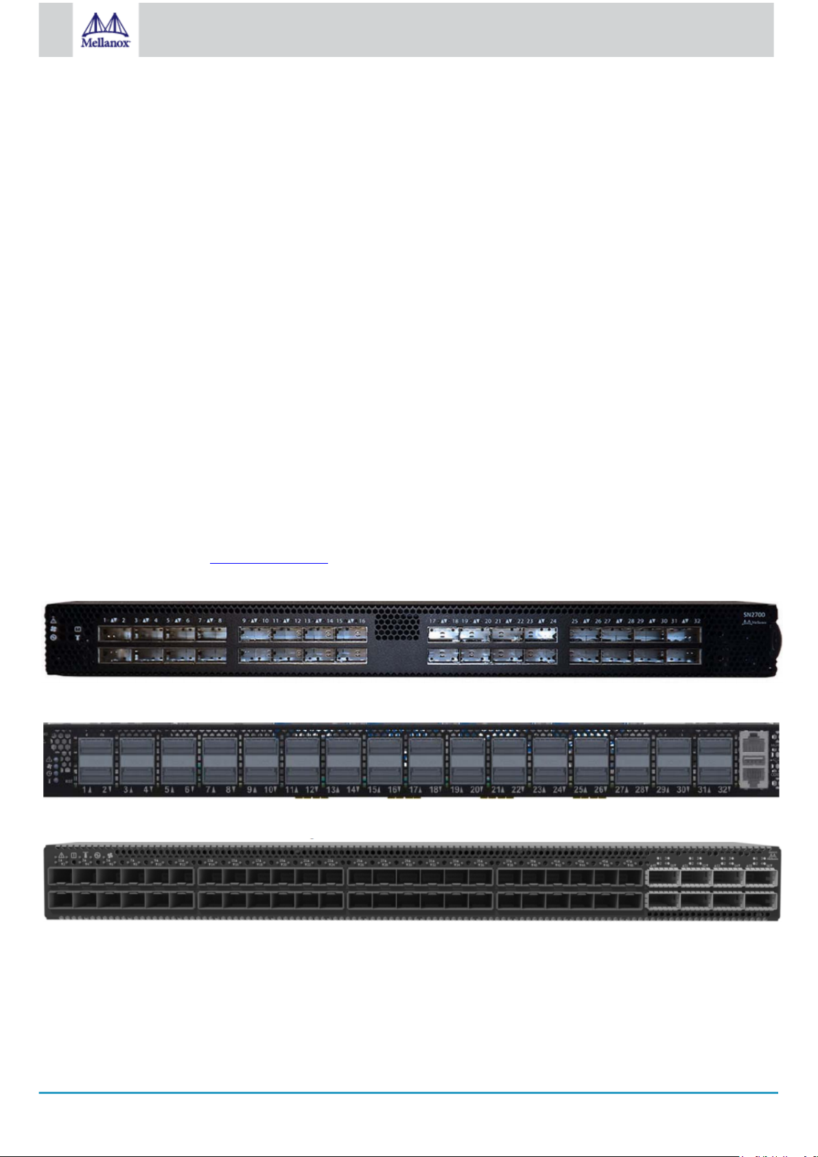
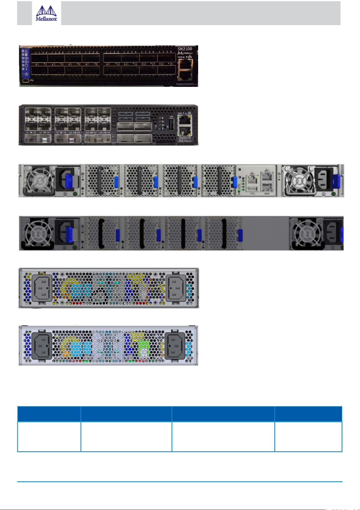
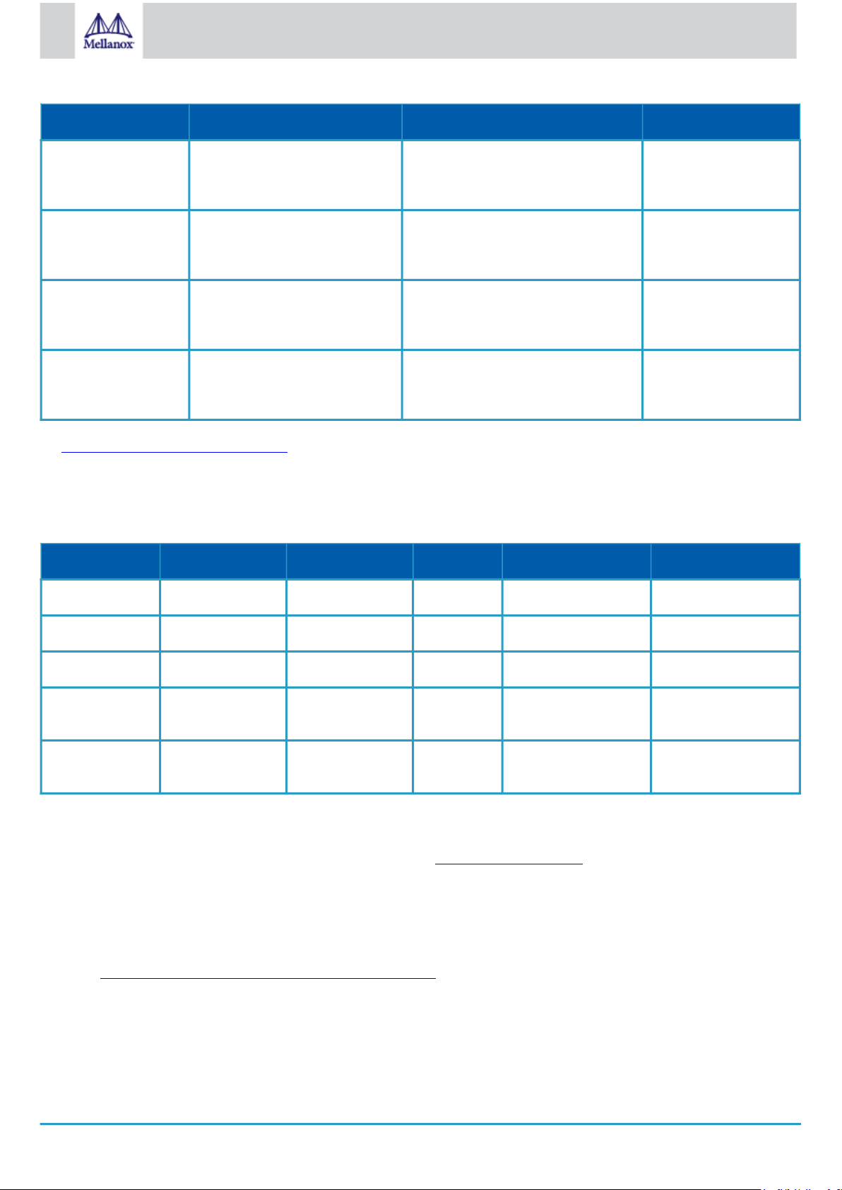
SN2700 Front View
SN2740 Front View
SN2410 Front View
SN2100 Front View
Page 11
11
Mellanox Technologies
SN2010 Front View
SN2700 and SN2410 Rear View
SN2740 Rear View
SN2100 Rear View
SN2010 Rear View
2.1 Speed and Switching Capabilities
The table below describes maximum throughput and interface speed per system model.
System Model 10/25GbE SFP28 Interfaces* 40/50/56/100GbE QSFP28 Interfaces* Max Throughput
SN2700 64
(using QSFP to SFP splitter
cables)
32 6.4Tb/s
Page 12
12
Mellanox Technologies
System Model 10/25GbE SFP28 Interfaces* 40/50/56/100GbE QSFP28 Interfaces* Max Throughput
SN2740 64
(using QSFP to SFP splitter
cables)
SN2410 Total 64, 48SFP+16
(using QSFP to SFP splitter
cables)
SN2100 64
(using QSFP to SFP splitter
cables)
SN2010 34
(using QSFP to SFP splitter
cables)
*The system can support different interfaces and speed rates using QSFP+ to SFP+ adapters or hybrid cables. For further information,
see Splitter (Breakout) Cables and Adapters.
(or 32 50GbE interfaces when using
QSFP to 2xQSFP splitter cables)
(or 8 50GbE interfaces when using
QSFP to 2xQSFP splitter cables)
32 6.4Tb/s
8 4Tb/s
16
4
3.2Tb/s
1.7Tb/s
2.2 Management Interfaces, PSUs and Fans
The table below lists the various management interfaces, PSUs and fans per system model.
System Model USB MGT Console PSU Fan
SN2700 Rear Rear (2 ports) Rear 2 units 4 units
SN2740 Front Front (1 port) Front 2 units 4 units
SN2410 Rear Rear (2 ports) Rear 2 units 4 units
SN2100 Front (mini USB) Front (1 port) Front 2 units (non-
replaceable)
SN2010 Front Front (1 port) Front 2 units (non-
replaceable)
4 units (nonreplaceable)
4 units (nonreplaceable)
2.3 Features
For a full feature list, please refer to the system’s product brief. Go to http://www.mellanox.com. In the main menu, click on Products
> Ethernet Switch Systems, and select the desired product page.
2.4 Certifications
The list of certifications (such as EMC, Safety and others) per system for different regions of the world is located on the Mellanox
website at http://www.mellanox.com/page/environmental_compliance.
Page 13
13
Mellanox Technologies
3 Installation
3.1 System Installation and Initialization
Installation and initialization of the system require attention to the normal mechanical, power, and thermal precautions for rackmounted equipment.
The rack mounting holes conform to the EIA-310 standard for 19-inch racks. Take precautions to guarantee proper
ventilation in order to maintain good airflow at ambient temperature.
Unless otherwise specified, Mellanox products are designed to work in an environmentally controlled data center with low
levels of gaseous and dust (particulate) contamination.
The operation environment should meet severity level G1 as per ISA 71.04 for gaseous contamination and ISO 14644-1
class 8 for cleanliness level.
The installation procedure for the system involves the following phases:
Step Procedure See
1 Follow the safety warnings Safety Warnings
2 Pay attention to the air flow consideration within the system
and rack
3 Make sure that none of the package contents is missing or
damaged
4 Mount the system into a rack enclosure 19" System Mounting Options
5 Power on the system Initial Power On
6 Perform system bring-up System Bring-Up
7 [Optional] FRU replacements FRU Replacements
Air Flow
Package Contents
3.2 Safety Warnings
Prior to the installation, please review the safety warnings. Note that not all warnings may apply to all models.
Safety warnings are provided here in the English language. For safety warnings in other languages, refer to the 1U Switch
Installation Safety Instructions document available on mellanox.com.
Safety Warnings (English)
Installation Instructions
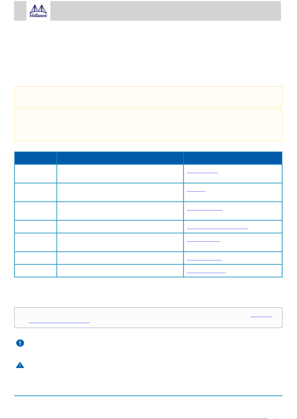
Read all installation instructions before connecting the equipment to the power source.
Bodily Injury Due to Weight
Page 14
14
Mellanox Technologies
Use enough people to safely lift this product.
Heavy Equipment
This equipment is heavy and should be moved using a mechanical lift to avoid injuries.
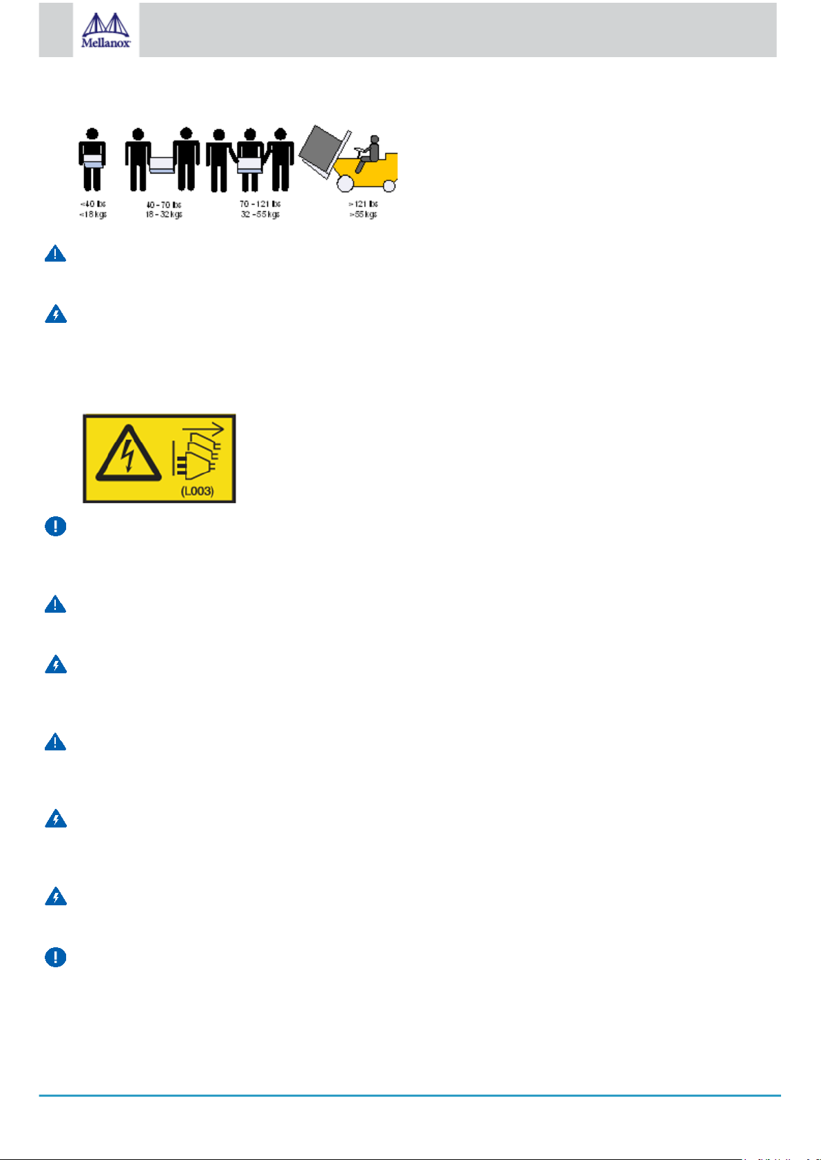
Risk of Electric Shock!
•
With the fan module removed power pins are accessible within the module cavity.
Do not insert tools or body parts into the fan module cavity.
•
For AC powered switch systems: Disconnecting one power supply only disconnects one module. To isolate the unit
completely, all connected power supplies must be disconnected.
Over-temperature
This equipment should not be operated in an area with an ambient temperature exceeding the maximum recommended: 45°C
(113°F). Moreover, to guarantee proper ventilation, allow at least 8cm (3 inches) of clearance around the ventilation openings.
Stacking the Chassis
The chassis should not be stacked on any other equipment. If the chassis falls, it can cause bodily injury and equipment damage.
Redundant Power Supply Connection - Electrical Hazard
This product includes a redundant power or a blank in its place. In case of a blank power supply, do not operate the product with
the blank cover removed or not securely fastened.
Double Pole/Neutral Fusing
This system has double pole/neutral fusing. Remove all power cords before opening the cover of this product or touching any
internal parts.
Multiple Power Inlets
Risk of electric shock and energy hazard. The PSUs are all independent. Disconnect all power supplies to ensure a powered
down state inside of the switch platform.
During Lightning - Electrical Hazard
During periods of lightning activity, do not work on the equipment or connect or disconnect cables.
Copper Cable Connecting/Disconnecting
Copper cables are heavy and not flexible, as such they should be carefully attached to or detached from the connectors. Refer to
the cable manufacturer for special warnings/instructions.
Page 15

15
Mellanox Technologies
Rack Mounting and Servicing
When this product is mounted or serviced in a rack, special precautions must be taken to ensure that the system remains stable.
In general you should fill the rack with equipment starting from the bottom to the top.
Equipment Installation
This equipment should be installed, replaced, and/or serviced only by trained and qualified personnel.
Equipment Disposal
Disposal of this equipment should be in accordance to all national laws and regulations.
Local and National Electrical Codes
This equipment should be installed in compliance with local and national electrical codes.
Installation Codes
This device must be installed according to the latest version of the country national electrical codes. For North America,
equipment must be installed in accordance to the applicable requirements in the US National Electrical Code and the Canadian
Electrical Code.
Battery Replacement
Warning: Replace only with UL Recognized battery, certified for maximum abnormal charging current not less than 4mA. There
is a risk of explosion should the battery be replaced with a battery of an incorrect type. Dispose of used batteries according to the
instructions.
UL Listed and CSA Certified Power Supply Cord
For North American power connection, select a power supply cord that is UL Listed and CSA Certified, 3 - conductor, [16
AWG], terminated with a molded plug rated at 125 V, [13 A], with a minimum length of 1.5m [six feet] but no longer than 4.5m.
For European connection, select a power supply cord that is internationally harmonized and marked “<HAR>”, 3 - conductor,
minimum 1.0 mm2 wire, rated at 300 V, with a PVC insulated jacket. The cord must have a molded plug rated at 250 V, 10 A.
Installation codes
This device must be installed according to the latest version of the country national electrical codes. For North America,
equipment must be installed in accordance to the applicable requirements in the US National Electrical Code and the Canadian
Electrical Code.
Interconnection of Units
Cables for connecting to the unit RS232 and Ethernet Interfaces must be UL certified type DP-1 or DP-2. (Note- when residing
in non LPS circuit)
Overcurrent Protection
A readily accessible Listed branch circuit overcurrent protective device rated 20 A must be incorporated in the building wiring.
Do Not Use the Switch as a Shelf or Work Space
Caution: Slide/rail mounted equipment is not to be used as a shelf or a work space. The rails are not intended for sliding
the unit away from the rack. It is for permanent installation at final resting place only, not used for service and maintenance
Page 16
16
Mellanox Technologies
WEEE Directive
According to the WEEE Directive 2002/96/EC, all waste electrical and electronic equipment (EEE) should be collected
separately and not disposed of with regular household waste. Dispose of this product and all of its parts in a responsible
and environmentally friendly way.
Country of Norway Power Restrictions
This unit is intended for connection to a TN power system and an IT power system of Norway only.
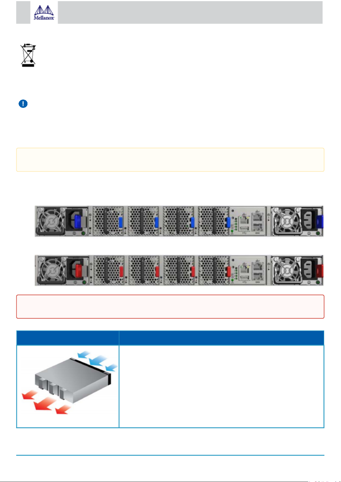
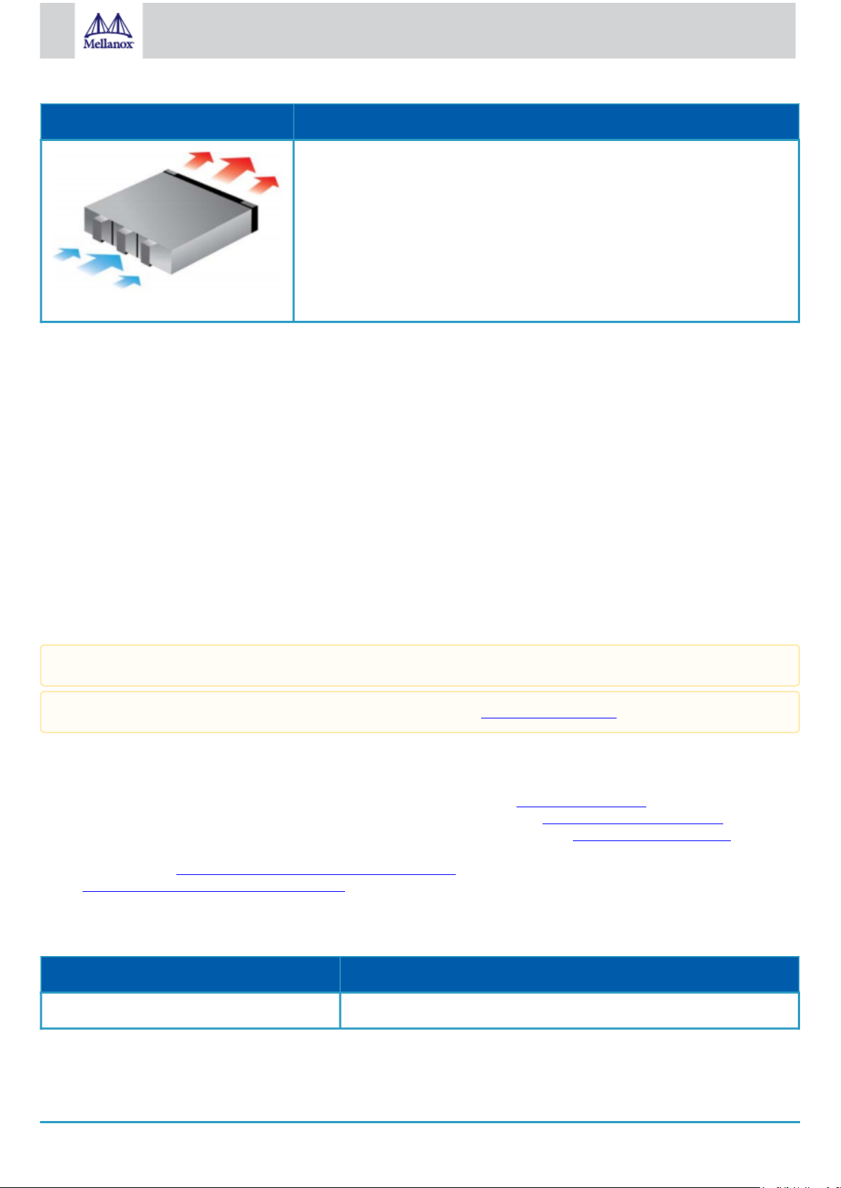
3.3 Air Flow
The following information does not apply to SN2100/SN2010. In the SN2100/SN2010 systems, the fan units are non-
replaceable.
Mellanox systems are offered with two air flow patterns:
•
Power (rear) side inlet to connector side outlet - marked with blue power supplies/fans FRUs’ handles.
Air Flow Direction Marking - Power Side Inlet to Connector Side Outlet
•
Connector (front) side inlet to power side outlet - marked with red power supplies/fans FRUs’ handles.
Air Flow Direction Marking - Connector Side Inlet to Power Side Outlet
All servers and systems in the same rack should be planned with the same airflow direction.
All FRU components need to have the same air flow direction. A mismatch in the air flow will affect the heat dissipation.
The table below provides an air flow color legend and respective OPN designation.
Direction Description and OPN Designation
Connector side inlet to power side outlet. Red latches are placed on the power inlet
side.
OPN designation is “-R”.
Page 17
17
Mellanox Technologies
Direction Description and OPN Designation
Power side inlet to connector side outlet. Blue latches are placed on the power inlet
side.
OPN designation is “-F”.
3.4 Package Contents
Before installing your new system, unpack it and check against the parts list below that all the parts have been sent. Check the parts
for visible damage that may have occurred during shipping.
The SN2700 and SN2410 package content is as follows:
•
1 – System
•
1 – Rail kit
•
1 – Power cable for each power supply unit – Type C13-C14
•
1 – Cable retainer for each power supply unit
•
1 – DB9 to RJ-45 2m harness
•
1 - RJ-45 to RJ-45 2m harness
The SN2100/SN2010 package content is as follows:
•
1 – System
•
1 – Power cable for each power supply unit – Type C13-C14
•
1 – DB9 to RJ-45 2m harness
A designated rail kit for the SN2100/SN2010 systems can be purchased separately.
If anything is damaged or missing, contact your sales representative at support@mellanox.com.
3.5 19” System Mounting Options
•
By default, the SN2700 systems are shipped with the static rail kit described SN2700 Static Rail Kit.
•
The SN2410 and SN2740 systems are shipped with the static rail kit described in SN2740/SN2410 Static Rail Kit.
•
For the telescopic rail kit installation instructions (can be used with SN2700 only), see SN2700 Telescopic Rail Kit.
•
The SN2100/SN2010 system is shipped without a rail kit and a designated rail kit can be purchased separately. For installation
instructions, see SN2100/SN2010 Side by Side Mounting Rail Kit.
•
SN2100/SN2010 Static Single Switch Rail Kit
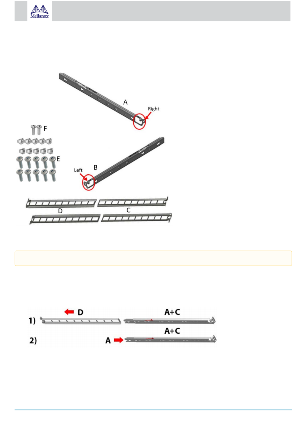
3.6 SN2700 Static Rail Kit
Kit OPN Rack Size and Rack Depth Range
MTEF-KIT-A Short (17”-24”) or Standard (24”-34”)
The following parts are included in the static rail kit (see figure below):
•
2x Rack mount rails (A)
Page 18
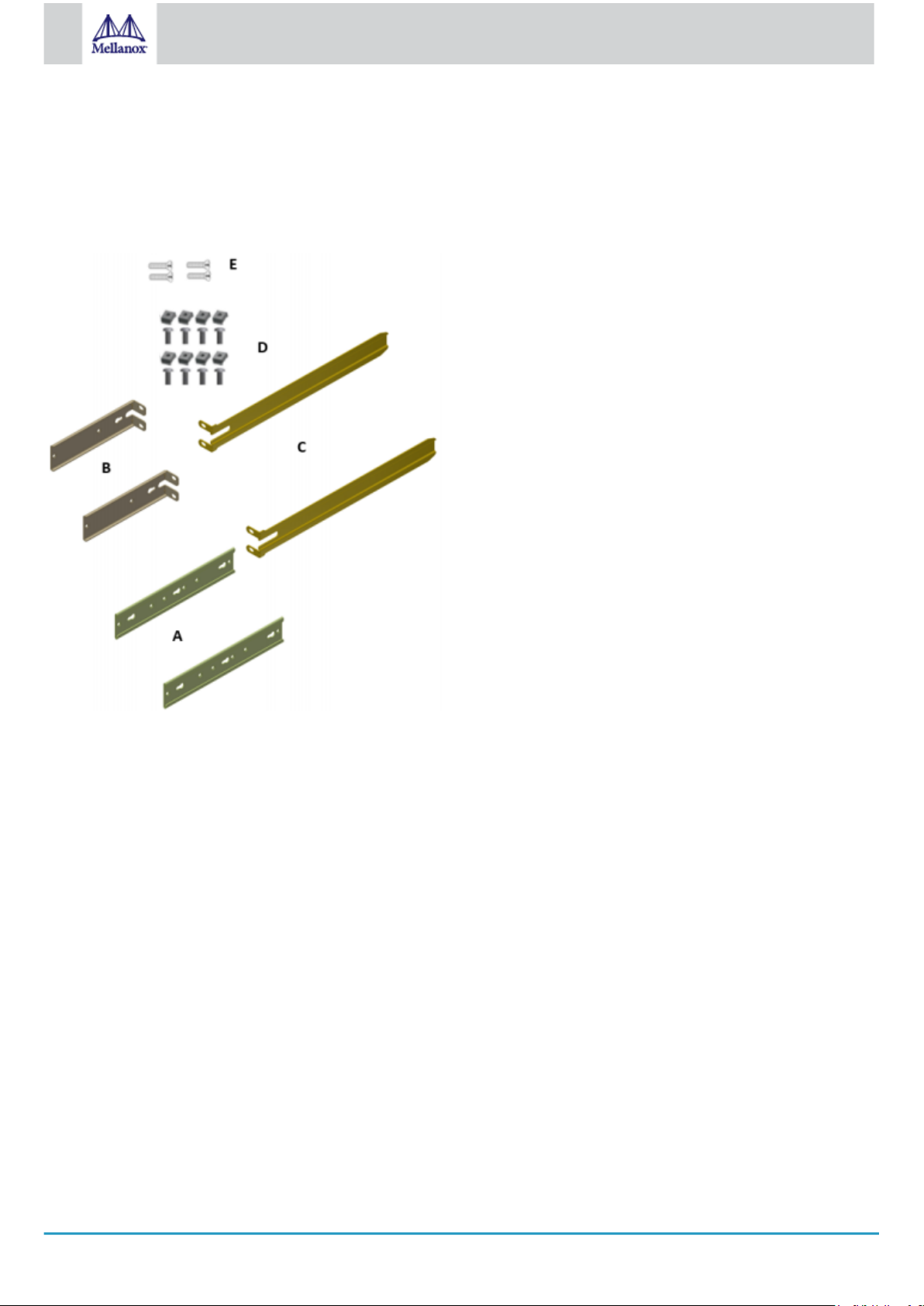
18
Mellanox Technologies
•
2x Rack mount brackets (B)
•
2x Rack mount blades (C)
•
8x M6 Standard cage nuts¹ ² and 8x M6 Standard pan-head Phillips screws¹ (D)
•
4x Phillips100 DEG F.H TYPE-I ST.ST 6-32 X 1/4 screws with a round patch (E)
¹ Other threads are available by special order: M5, 10-32, 12-24. ² G-type cage-nut is available by special order.
Rack Rail Kit Parts
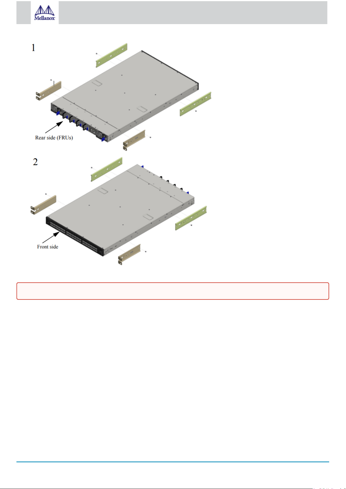
Prerequisites:
Before mounting the system to the rack, select the way you wish to place the system. Pay attention to the airflow within the rack
cooling, connector and cabling options.
While planning how to place the system, consider the two installation options shown in the figure below, and review the following
points:
•
Make sure the system air flow is compatible with your installation selection. It is important to keep the airflow within the rack
in the same direction.
•
Note that the part of the system to which you choose to attach the rails (the front panel direction, as demonstrated in Option 1
or the FRUs direction, as demonstrated in Option 2) will determine the system’s adjustable side. The system’s part to which
the brackets are attached will be adjacent to the cabinet.
•
The FRU side is extractable. Mounting the rack brackets inverted to the FRU side (Option 2) will allow you to slide the FRUs,
in and out.
Installation Option 1 & Option 2
Page 19
19
Mellanox Technologies
To mount the system into the rack:
At least two people are required to safely mount the system in the rack.
1.
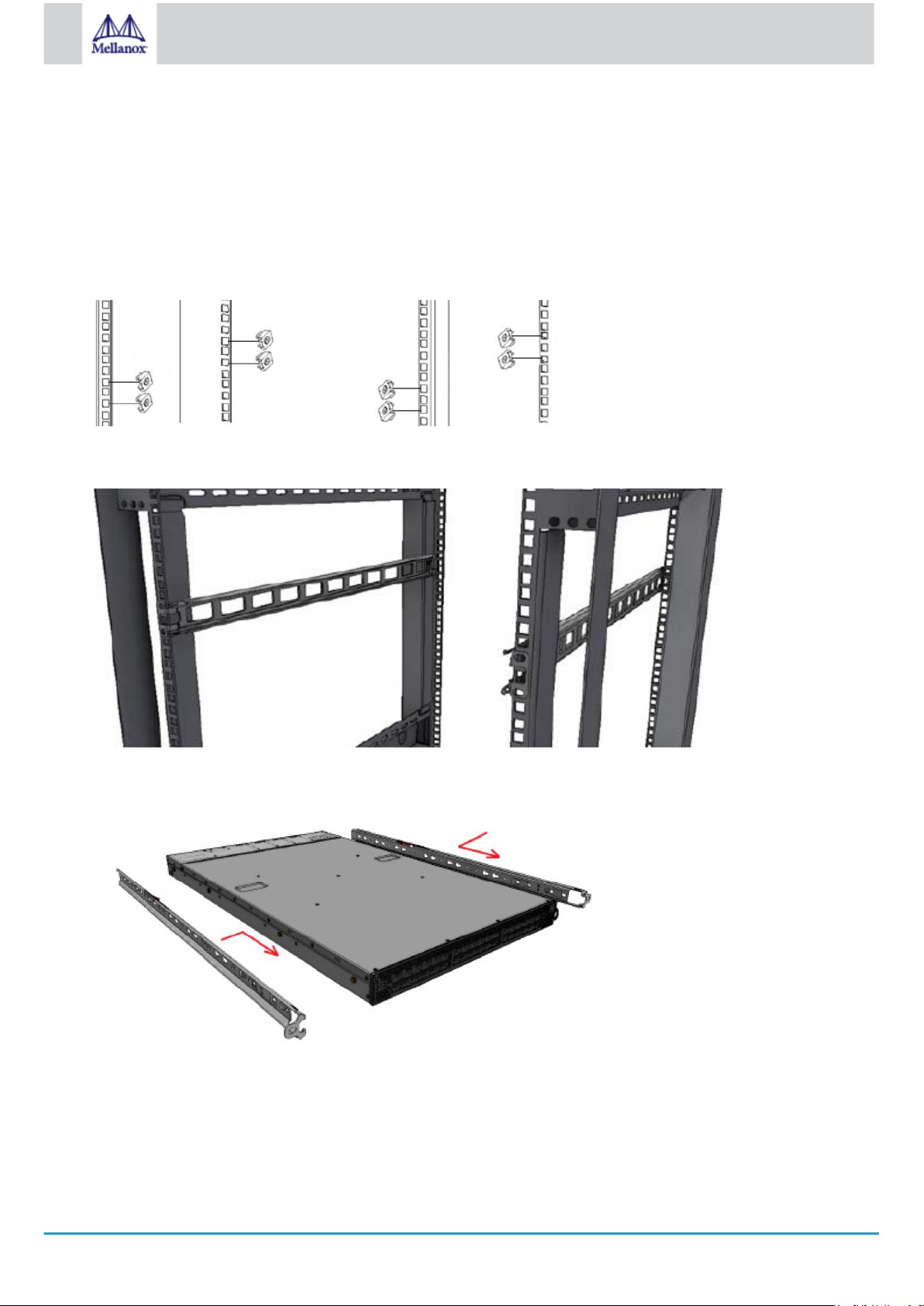
Attach the left and right rack mount rails (A) to the switch, by gently pushing the switch chassis’ pins through the slider key
holes, until locking occurs.
2.
Secure the chassis in the rails by screwing 2 flat head Phillips screws (E) in the designated points with a torque of 1.5±0.2
Nm.
Page 20
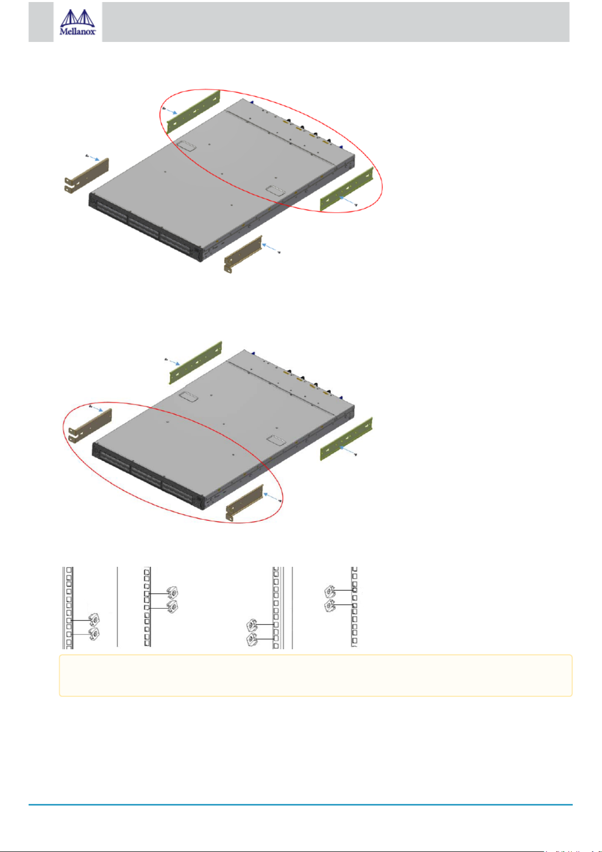
20
Mellanox Technologies
Attaching the Rails to the Chassis
3.
Attach the left and right rack mount brackets (B) to the switch, by gently pushing the switch chassis’ pins through the slider
key holes, until locking occurs. Secure the system in the brackets by screwing the remaining 2 flat head Phillips screws (E) in
the designated points with a torque of 1.5±0.2 Nm.
Attaching the Brackets to the Chassis
4.
Install 8 cage nuts in the desired slots of the rack: 4 cage nuts in the non-extractable side (in the top and bottom holes only)
and 4 cage nuts in the extractable side.
Installing the Cage Nuts
While each rack U (unit) consists of three holes, the cage nut should be installed vertically with its ears engaging the
top and bottom holes only.
While your installation partner is supporting the system’s weight, perform the following steps:
5.
Mount the system into the rack enclosure, and attach the brackets installed on the system to the rack’s posts. Secure the
brackets to the rack’s posts by inserting four M6 screws in the designated cage nuts, as described in the figure below. Do not
tighten the screws yet.
Page 21
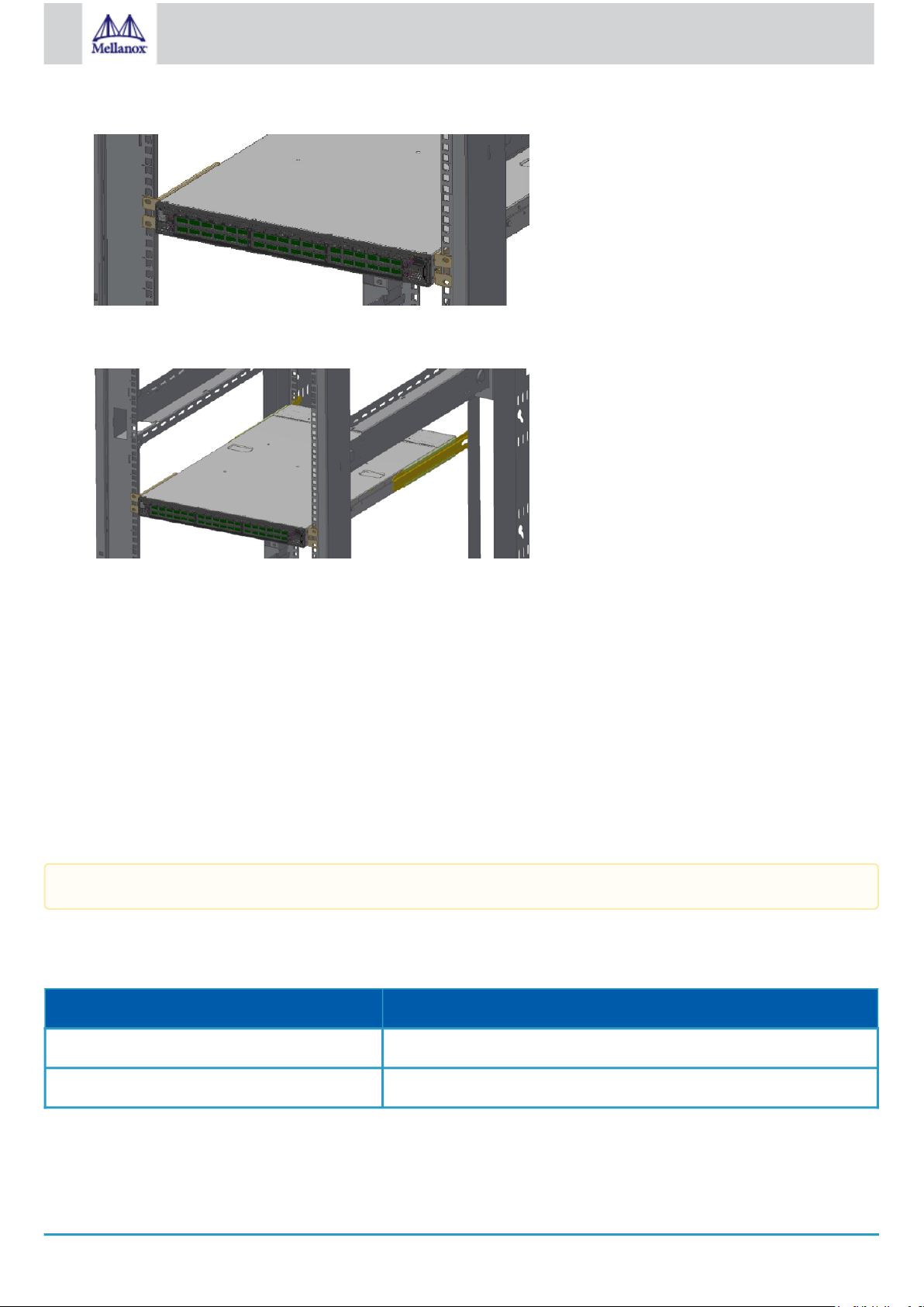
21
Mellanox Technologies
Attaching the Brackets to the Rack
6.
Slide the two blades into the left and right rails, and adjust them to fit your rack's depth. Use four M6 screws (D) to fix the
blades into the rack. Do not tighten the screws yet.
Sliding the Blades in the Rails
7.
Secure the system in the rack by tightening the 8 screws inserted in Step 5 and Step 6 with a torque of 4.5±0.5 Nm.
3.6.1 Removing the System from the Rack
To remove a unit from the rack:
1.
Turn off the system and disconnect it from peripherals and from the electrical outlet.
While your installation partner is supporting the system’s weight:
2.
Loosen the screws attaching the brackets to the rack. Do not remove them yet.
3.
Loosen the screws attaching the blades to the rack, and pull the blades towards you, while your partner is holding the system.
4.
Extract the loosened screws from Step 2 and dismount the system from the rack.
5.
Remove the rails and brackets from the chassis by unscrewing 8 screws.
3.7 SN2700 Telescopic Rail Kit
The telescopic rail kit is not included in the system’s package, and can be purchased separately.
There are two installation kit options:
•
Standard depth systems should be mounted using the standard rail kit.
•
Short depth systems can be mounted using either of the rail kits.
Kit OPN Rack Size and Rack Depth Range
MTEF-KIT-B Short: 17"-24" (43.1 to 61 cm)
MTEF-KIT-S Standard: 24"-34" (61 to 86.3 cm)
The following parts are included in the rail kit package (see figure below):
•
1x Right inner rail (A) +2x Outer rails (C) - Bundled
•
1x Left inner rail (B) + 2x Outer rails (D) - Bundled
Page 22
22
Mellanox Technologies
•
10x M6 Standard cage nuts¹ ² and 10x M6 Standard pan-head Phillips screws¹ (E)
•
2x Phillips100 DEG F.H TYPE-I ST.ST 6-32 X 1/4 screw with a round patch (F)
¹ Other threads are available by special order: M5, 10-32, 12-24. ² G-type cage-nut is available by special order.
Rack Rail Kit Parts
Prerequisites
The rails must be separated prior to the installation procedure.
To separate the rails:
1.
Extend the rail assembly by pulling the extension outwards (D).
2.
Extract rail A from rail C by pushing it outside from the rear part of the assembly. To allow complete separation of rail A from
rail C, press the quick-release latch.
Rails Separation
Before mounting the system to the rack, select the way you wish to place the system. Pay attention to the airflow within the rack
cooling, connector and cabling options.
While planning how to place the system, review the following points:
•
Make sure the system air flow is compatible with your installation selection. It is important to keep the airflow within the rack
in the same direction.
Page 23
23
Mellanox Technologies
•
In case there are cables that cannot bend within the rack, or in case more space is needed for cable bending radius, it is
possible to recess the connector side or the FRU side by 3” or 4” (7.62 or 10.16cm) by optional placement of the system’s
rails.
•
The FRU side is extractable. Mounting the sliding rail inverted to the system will allow you to slide the FRU side of the
system, in and out.
To mount the system into the rack:
1.
Insert 10 cage nuts into the desired slots of the rack: 4 cage nuts in the non-extractable side and 6 cage nuts in the extractable
side.
Installing the Cage Nuts
2.
Mount both of the outer rails (C+D) into the rack (as illustrated below), and use 8 standard pan-head screws (E) to fix them to
the rack. Do not tighten the screws yet.
Mounting the Outer Rails into the Rack
3.
If cable accommodation is required, route the power cable and/or Eth cable through either of the outer rails.
4.
Attach left and right inner rails (A+B) to the switch sides, by gently pushing the switch chassis’ pins through the slider key
holes, until locking occurs.
Attaching the Inner Rails
5.
Secure the chassis in the inner rails by screwing the 2 flat head Phillips screws (F) in the designated points with a torque of
1.5±0.2 Nm.
Securing the Chassis in the Inner Rails
Page 24

24
Mellanox Technologies
6.
Slide the switch into the rack by carefully pushing the inner rails into the outer rails installed on the rack.
Sliding the Switch into the Rack
7.
When fully inserted, fix the switch by closing the remaining 2 screws in the middle and tightening the 8 screws inserted in
Step 2 with a torque of 4.5±0.5 Nm.
3.7.1 Removing the System from the Rack
To remove a unit from the rack:
1.
Turn off the system and disconnect it from peripherals and from the electrical outlet.
2.
Unscrew the two M6 screws securing the front of the inner rails’ ears to the outer rails and to the rack.
3.
Pull the unit out until braking is felt. For safety purposes, the locking mechanism will not allow a complete removal of the unit
at this stage.
Pulling the Unit Outwards
4.
Press on the locking spring (appears in red in the figure below) on both sides simultaneously, and continue pulling the unit
towards you until it is fully removed.
Page 25

25
Mellanox Technologies
Locking Mechanism
3.8 SN2740/SN2410 Static Rail Kit
By default, the system is sold with the standard-depth rail kit. The short-depth rail kit can be supplied upon request.
Kit OPN Rack Size and Rack Depth Range
MTEF-KIT-BP Short: 19.7"-23.6" (50 to 60 cm)
MTEF-KIT-SP Standard: 23.6"-31.5" (60 to 80 cm)
The following parts are included in the static rail kit (see figure below):
•
2x Rack mount rails (A)
•
2x Rack mount blades (B)
•
8x M6 Standard cage nuts¹ ² and 8x M6 Standard pan-head Phillips screws¹ (C)
•
4x Phillips100 DEG F.H TYPE-I ST.ST 6-32 X 1/4 screw with around patch (D).
¹ Other threads are available by special order: M5, 10-32, 12-24. ² G-type cage-nut is available by special order.
Rack Rail Kit Parts
Prerequisites
Before mounting the system to the rack, select the way you wish to place the system. Pay attention to the airflow within the rack
cooling, connector and cabling options.
While planning how to place the system, consider the two installation options shown in the Installation Options figure below, and
review the following points:
Page 26

26
Mellanox Technologies
•
Make sure the system air flow is compatible with your installation selection. It is important to keep the airflow within the rack
in the same direction.
•
Note that the part of the system to which you choose to attach the rails (the front panel direction, as demonstrated in Option 1
or the FRUs direction, as demonstrated in Option 2) will determine the system’s adjustable side. The system’s part to which
the blades are attached, will be adjacent to the cabinet.
•
In case there are cables that cannot bend within the rack, or in case more space is needed for cable bending radius, it is
possible to recess the connector side or the FRU side by 3.5" (8.9 cm), by optional placement of the system’s rails.
•
The FRU side is extractable. Mounting the rack blades inverted to the FRU side (Option 2) will allow you to slide the FRUs,
in and out.
Installation Options
To mount the system into the rack:
At least two people are required to safely mount the system in the rack.
1.
Attach the left and right rack mount rails (A) to the switch, and secure the chassis in the rails by screwing 2 flat head Phillips
screws (D) in the designated points on each side (a total of 4 screws). To tighten the screws, use a torque of 1.5±0.2 Nm.
Attaching the Rails to the Chassis
Page 27

27
Mellanox Technologies
2.
Install 8 cage nuts (C) in the desired slots of the rack: 4 cage nuts in the non-extractable side and 4 cage nuts in the extractable
side. Note that while each rack U (unit) consists of three holes, the cage nut should be installed vertically with its ears
engaging the top and bottom holes only.
Installing the Cage Nuts
While your installation partner is supporting the system’s weight, perform steps 3, 4 and 5:
3.
On the rear side of the cabinet, install the two blades (B) in the selected rack unit, using four M6 screws (C). Do not tighten the
screws yet.
Attaching the Rails to the Rack
4.
Slide the two blades into the left and right rails, and adjust them to fit your rack's depth. Use four M6 screws (D) to fix the
blades into the rack. Do not tighten the screws yet.
Sliding the Blades in the Rails
5.
Secure the system in the rack by tightening the 8 screws inserted in Step 3 and Step 4 with a torque of 4.5±0.5 Nm.
3.9 SN2100/SN2010 Side by Side Mounting Rail Kit
The installation process is demonstrated on an SN2100 system, but applies to the SN2010 series as well.
A designated rail kit for the SN2100/SN2010 systems can be purchased separately.
This section is relevant to short-depth systems that allow such a form of installation only.
Kit OPN Rack Size and Rack Depth Range
MTEF-KIT-D Rack installation kit for SN2100/SN2010 series short depth 1U switches, allows installation of one or two
switches side-by-side into standard depth racks.
The following parts are included in the rail kit (see figure below):
•
1 metal frame for two systems (A)
•
2 system mounting blades with 8 screw holes - the kit contains enough rails to install 2 systems (B)
Page 28

28
Mellanox Technologies
•
2 system mounting blades with 7 screw holes - the kit contains enough rails to install 2 systems (C)
•
2 blank (installed) covers (D)
•
30 flat head 4-40 screws - the kit contains enough screws to install 2 systems (E)
•
2 frame rail slides (F)
•
10 (+2 spare units) M6 pan head screws (G)
•
10 (+2 spare units) M6 spring washers (H)
•
10 (+2 spare units) M6 spring steel cage nuts (I)
•
6 (+2 spare units) cable-ties (J)
Rack Rail Kit Parts
Prerequisites
Before mounting the system to the rack, select the way you wish to place the system. Pay attention to the airflow within the rack
cooling, connector and cabling options.
•
The installation kits come with enough system mounted rails and flat head screws to install two systems.
•
The 2 system metal frame will fit into racks with from 23.6” (600mm) to 31.5” (800mm) space between the vertical supports.
•
You may choose to install your system in the right or in the left part of the metal frame. The following instructions apply to
installation in the right part. For installation in the frame’s left part, follow the same instructions, while replacing “right” with
“left”, and vice versa.
To mount the system into the rack:
At least two people are required to safely mount the system in the rack.
1.
Insert the SE (single ended) plugs to the dedicated inlets in the system’s rear panel.
2.
Carefully position the SE (single ended) cables one on top of the other, and use three cable ties to pair them together (shown in
figure).
While pairing the cables, make sure the cables are paired in symmetry to the switch, in order to avoid damaging the
cables.
Coupling the Cables with Cable-ties
Page 29

29
Mellanox Technologies
Coupled Cables - Rear View
3.
Place the coupled cables in the designated area within the right flat blade (the blade with 7 screw holes).
Cables within the Rail
In the next step you will be attaching the mounting rails to the switch sides. Before doing that, make sure the cables
are laid properly within them. Avoid using excessive pressure, as it can damage the cables.
4.
While holding the cables stably together in the blade’s rail with one hand, use your other hand to secure the blades to the
chassis. Screw the right blade with eight 4-40 flathead screws, and the left blade with seven 4-40 flathead screws. The
recommended torque is 0.49-0.54 Nm.
Attach the Blades to the System
Attached Rail with Threaded Cables - Top View
Page 30

30
Mellanox Technologies
5.
Slide the two frame slides into the dedicated rails in the metal frame.
Sliding the Frame Sliders into the Rails
6.
Step 6. Install ten cage nuts in the desired slots of the rack: three cage nuts in the front part of each cabinet post, and two cage
nuts in the rear part of each cabinet post.
Installing the Cage Nuts
7.
Attach the frame to the rack by using ten spacer cage nuts, and screw ten M6 pan head screws - four in the front part of the
rack, and 6 in its rear part. The recommended torque is 6.55-7.35 Nm. See figure above.
8.
Place the frame in the cabinet.
Attaching the Frame to the Rack
Page 31

31
Mellanox Technologies
Do not remove both of the blank covers at the same time. When no system is installed, at least one of them should be
present to support the frame’s partition.
9.
Remove the blank cover from the selected slot in the frame, and mount the system by sliding its mounting blades into the
frame. Repeat this step to install an additional system in the other side of the frame, if needed.
10.
Tighten the capture nuts to secure the system in the frame. The recommended torque on the right screw is 3.0-3.36 Nm while
on the left screw recommended torque is 0.89-0.98 Nm.
Sliding the System’s Blades in the Rails
3.10 SN2100/SN2010 Static Single Switch Rail Kit
The installation process is demonstrated on an SN2100 system, but applies to the SN2010 series as well.
This rail kit is not included with the SN2100/SN2010 systems, and can be purchased separately.
This section is relevant to short-depth systems that allow such form of installation only.
Kit OPN Rack Size and Rack Depth Range
MTEF-KIT-E Rack installation static kit for SN2100/SN2010 systems short depth 1U half-width
switches, allows installation of a single switch into standard depth racks.
Page 32

32
Mellanox Technologies
The following parts are included in the rail kit (see figure below):
•
16 flat head 4-40 screws (A)
•
8 M6 spring steel cage nuts (B)
•
8 M6 pan head screws (C)
•
8 M6 spring washers (D)
•
8 M6 flat washers (E)
•
2 rack mount blades (F)
•
2 system brackets (G)
Rack Rail Kit Parts
To mount the system into the rack:
At least two people are required to safely mount the system in the rack.
1.
Attach the 2 system rails to the system’s sides using 8 flat head 4-40 screws (A) in each side.
Attaching the Brackets to the System’s Sides
2.
Install 8 cage nuts of the relevant type - square or round holes, according to your rack type.
Installing the Cage Nuts
While your installation partner is supporting the system’s weight, perform steps 3 and 4:
3.
On the rear side of the cabinet, install the two blades (F) in the selected rack unit, using four M6 screws and washers (C+D+E).
Do not tighten the screws yet.
Page 33

33
Mellanox Technologies
Attaching the Blades to the Rack
4.
Mount the system into the rack enclosure by sliding the rails in the rack. Secure the brackets to the rack’s posts by inserting
four M6 screws and washers (C+D+E) in the designated cage nuts - 2 in each side. Tighten all screws.
Attaching the Brackets to the Rack
3.11 Cable Installation
All cables can be inserted or removed with the unit powered on.
To insert a cable, press the connector into the port receptacle until the connector is firmly seated. The LED indicator, corresponding to
each data port, will light when the physical connection is established. When a logical connection is made, the relevant port LED will
turn on.
To remove a cable, disengage the locks and slowly pull the connector away from the port receptacle. The LED indicator for that port
will turn off when the cable is unseated.
For full cabling guidelines, ask your Mellanox representative for a copy of
Application Note.
For more information about port LEDs, refer to Port LEDs.
Do not force the cable into the cage with more than 40 newtons / 9.0 pounds / 4kg force. Greater insertion force may cause
damage to the cable or to the cage.
SN2700, SN2100 and SN2010 QSFP Cable Orientation
Mellanox Cable Management Guidelines and FAQs
Page 34

34
Mellanox Technologies
SN2010 SFP Cable Orientation
SN2740 Cable Orientation
SN2410 Cable Orientation
Page 35

35
Mellanox Technologies
The SN2410 system includes ports of different types. The figure above does not apply to the SFP28 ports; see "SN2410
Splitting Options" below.
3.11.1 Splitter (Breakout) Cables and Adapters
A 100GbE port can be split to two 50GbE ports, or to four (or less) 25GbE ports, using a Mellanox splitter cable.
Splitting a 100GbE QSFP28 port to 4 separate 25GbE ports (using a splitter cable) disables (unmaps) the 100GbE port below it. See
“SN2700 and SN2740 Splitting Options” below.
3.11.1.1 Using Splitter (Breakout) Cables with Mellanox Onyx (MLNX-OS)
When using this feature, you should log into the Mellanox Onyx (MLNX-OS) CLI and configure the individual ports to be ‘split-2’ or
‘split-4’. For further information on Mellanox’s cable, visit http://www.mellanox.com/page/interconnect_overview.
3.11.1.2 Using Splitter (Breakout) Cables with Cumulus Linux
If you are using 4x10G direct attach copper cables or active optical cables, edit the /etc/cumulus/ports.conf to enable support for these
cables, then restart the switchd service using the sudo systemctl restart switchd command. For more details, see Layer 1 and Switch
Port Attributes in the Cumulus Linux User Guide.
Examples of Splitter (Breakout or Fanout) Cables
3.11.1.3 SN2700 and SN2740 Splitting Options
The top QSFP28 ports marked in green are splittable to 4 SFP28 ports, each.
The bottom QSFP28 ports (gray) are blocked when the upper ports are in split mode.
All QSFP28 ports can be split to 2 QSFP28 ports.
Page 36

36
Mellanox Technologies
3.11.1.4 SN2410 Splitting Options
The top QSFP28 ports – 49, 51, 53, 55 (green) – are splittable to 4 SFP28 ports each.
All QSFP28 ports can be split into two QSFP28 ports.
The bottom QSFP28 ports – 50, 52, 54, 56 (gray) – are blocked when the upper ports are in split mode.
3.11.1.5 SN2100 Splitting Options
All QSFP28 ports are splittable. Each port can be split into 4xSFP28 (10/25G) or 2xQSFP28 (50G) ports. There are no blocking
requirements.
3.11.1.6 SN2010 Splitting Options
All QSFP28 ports are splittable. Each port can be split into 4xSFP28 (10/25G) or 2xQSFP28 (50G) ports each. There are no blocking
requirements.
Page 37

37
Mellanox Technologies
3.12 Initial Power On
Each system’s input voltage is specified in the Specifications chapter.
The power cords should be standard 3-wire AC power cords including a safety ground and rated for 15A or higher.
The system platform will automatically power on when AC power is applied. There is no power system. Check all boards,
power supplies, and fan tray modules for proper insertion before plugging in a power cable.
1.
Plug in the first power cable.
2.
Plug in the second power cable.
3.
Wait for the System Status LED to turn green.
It may take up to five minutes to turn on the system. If the System Status LED shows red after five minutes, unplug
the system and call your Mellanox representative for assistance.
4.
Check the System Status LEDs and confirm that all of the LEDs show status lights consistent with normal operation (initially
flashing, and then moving to a steady color) as shown in the figures below. For more information, refer to LED Notifications.
System Status LEDs 5 Minutes After
Power On in SN2700
System Status LEDs 5 Minutes After Power On in SN2100 System Status LEDs 5 Minutes After Power On in SN2010
System Status LEDs 5 Minutes After
Power On in SN2740
System Status LEDs 5 Minutes After
Power On in SN 2410
Page 38

38
Mellanox Technologies
After inserting a power cable and confirming the green System Status LED light is on, make sure that the Fan Status LED
shows green. If the Fan Status LED is not green, unplug the power connection and check that the fan module is inserted
properly and that the mating connector of the fan unit is free of any dirt and/or obstacles. If no obstacles were found and the
problem persists, call your Mellanox representative for assistance.
Two Power Inlets - Electric Caution Notifications:
•
Risk of electric shock and energy hazard. The two power supply units are independent. Disconnect all power supplies
to ensure a powered down state inside of the switch platform.
•
ACHTUNG Gafahr des elektrischen Schocks. Entferrnen des Netzsteckers elnes Netzteils spannungsfrei. Um alle
Einhieten spannungsfrei zu machen sind die Netzstecker aller Netzteile zu entfernen.
•
ATTENTION Risque de choc et de danger e’lectriques. Le de’branchment d’une seule alimentation stabilise’e ne
de’branch uniquement qu’un module “Alimentation Stabilise’e”. Pour isoler completement le module en cause, Il
faut de’brancher toutes les alimentations stabilise’es.
3.13 System Bring-Up
For bring-up of a switch system with Mellanox Onyx (MLNX-OS) operating system installed, see Configuring Network Attributes
Using Mellanox Onyx (MLNX-OS).
For bring-up of a switch system with Cumulus Linux operating system installed, see Configuring Network Attributes Using Cumulus
Linux.
3.13.1 Configuring Network Attributes Using Mellanox Onyx (MLNX-OS)
The procedures described in this chapter assume that you have already installed and powered on the system according to the
instructions in this document. The system comes with a pre-configured DHCP. If you wish to disable it, refer to Disable Dynamic
Host Configuration Protocol (DHCP). In case a manual configuration is required, please refer to the instructions in Manual Host Configuration.
3.13.1.1 Manual Host Configuration
To perform initial configuration of the system:
Step 1. Connect a host PC to the Console RJ45 ( ) port of the system, using the supplied harness cable (DB9 to RJ45). Make
sure to connect to the Console RJ45 port and not to the (Ethernet) MGT ( ) port.
Step 2. Configure a serial terminal program (for example, HyperTerminal, minicom, or Tera Term) on your host PC with the settings
described in the table below. Once you perform that, you should get the CLI prompt of the system.
Serial Terminal Program Configuration
Parameter Setting
Baud Rate 115200
Data bits 8
Stop bits 1
Parity None
Page 39

39
Mellanox Technologies
Parameter Setting
Flow Control None
Step 3. Login as admin and use admin as password. On the first login, the Mellanox Onyx (MLNX-OS) configuration wizard will
start.
Step 4. To configure network attributes and other initial parameters to the system, follow the configuration wizard as shown in the
Configuration Wizard Session table below.
Configuration Wizard Session
Wizard Session Display Comments
Mellanox configuration wizard
Do you want to use the wizard for initial configuration?
yes
You must perform this configuration the first time you operate
the system or after resetting the system. Type ‘y’ and then press
<Enter>.
Step 1: Hostname? [switch-1] If you wish to accept the default hostname, press <Enter>.
Otherwise, type a different hostname and press <Enter>.
Step 2: Use DHCP on mgmt0 interface? [no] yes Perform this step to obtain an IP address for the system. (mgmt0
is the management port of the system).
If you wish the DHCP server to assign the IP address, type ‘yes’
and press <Enter>.
If you type ‘no’ (no DHCP), then you will be asked whether you
wish to use the ‘zeroconf’ configuration or not.
If you enter ‘no’ (no Zeroconf), you must enter a static IP, and
the session will continue.
Step 3: Enable IPv6? [yes] The management interface will be able to use IPv6 addresses.
If you enter "no" (no IPv6), you will automatically be referred to
Step 6.
Step 4: Enable IPv6 auto-config (SLAAC) on mgmt0
interface? [no]
This turns on auto-configuration of the IPv6 addresses. This is
unsuitable for DHCPv6.
Step 5: Enable DHCPv6 on mgmt0 interface? [no] To enable DHCPv6 on the MGMT0 interface.
Step 6: Admin password (Press <Enter> to leave
unchanged)? <new_password>
Step 6: Confirm admin password? <new_password>
You have entered the following information:
<A summary of the configuration is now displayed.>
To change an answer, enter the step number to return to
or hit <enter> to save changes and exit.
Choice: <Enter>
Configuration changes saved.
To avoid illegal access to the machine, please type a password
and then press <Enter>. Then confirm the password by reentering it. Note that password characters are not printed.
The wizard displays a summary of your choices and then asks
you to confirm the choices or to re-edit them.
Either press <Enter> to save changes and exit, or enter the
configuration step number that you wish to return to.
Note: To re-run the configuration wizard, run the command
“configuration jump-start” in Config mode.
Page 40

40
Mellanox Technologies
The table below shows an example of static IP configuration for mgmt0 interface.
Mellanox configuration wizard
Do you want to use the wizard for initial configuration? yes
Step 1: Hostname? []
Step 2: Use DHCP on mgmt0 interface? [yes] no
Step 3: Use zeroconf on mgmt0 interface? [no]
Step 4: Primary IP address? [for example 192.168.10.4] 10.10.10.10
Mask length may not be zero if address is not zero (interface eth0)
Step 5: Netmask? [0.0.0.0] 255.255.255.0
Step 6: Default gateway? [for example 192.168.10.1] 10.10.10.255
Step 7: Primary DNS server?
Step 8: Domain name?
Step 9: Enable IPv6? [yes]
Step 10: Enable IPv6 autoconfig (SLAAC) on mgmt0 interface? [no]
Step 11: Admin password (Enter to leave unchanged)?
To change an answer, enter the step number to return to.
Otherwise hit <enter> to save changes and exit.
Choice:
Configuration changes saved.
To return to the wizard from the CLI, enter the “configuration jump-start”
command from configure mode. Launching CLI...
Configuration Wizard Session - Static IP Configuration
Step 5. Before attempting a remote (for example, SSH) connection to the system, check the mgmt0 interface configuration.
Specifically, verify the existence of an IP address. To check the current mgmt0 configuration, enter the following command:
Page 41

41
Mellanox Technologies
switch01 (config) # show interfaces mgmt0
Interface mgmt0 status:
Comment:
Admin up: yes
Link up: yes
DHCP running: yes
IP address: 192.168.1.100
Netmask: 255.255.255.0
IPv6 enabled: yes
Autoconf enabled: no
Autoconf route: yes
Autoconf privacy: no
DHCPv6 running: no
IPv6 addresses: 1
IPv6 address: fe80::202:c9ff:fe63:b55a/64
Speed: 1000Mb/s (auto)
Duplex: full (auto)
Interface type: ethernet
Interface source: physical
MTU: 1500
HW address: 00:02:C9:63:B5:5A
RX bytes: 968810197 TX bytes: 1172590194
RX packets: 10982099 TX packets: 10921755
RX mcast packets: 0 TX discards: 0
RX discards: 0 TX errors: 0
RX errors: 0 TX overruns: 0
RX overruns: 0 TX carrier: 0
RX frame: 0 TX collisions: 0
TX queue len: 1000
switch01 (config) #
Step 6. Check the software version embedded in your system, using the command ‘show version’. Compare this version to the latest
version that can be retrieved from Mellanox support site. To upgrade software, please refer to the
Manual
.
3.13.1.2 Disable Dynamic Host Configuration Protocol (DHCP)
DHCP is used for automatic retrieval of management IP addresses.
If a user connects through SSH, runs the wizard and turns off DHCP, the connection is immediately terminated, as the management
interface loses its IP address. In such a case, the serial connection should be used.
<localhost># ssh admin@<ip-address>
Mellanox Onyx (MLNX-OS) Switch Management
Password:
Mellanox Switch
Mellanox configuration wizard
Do you want to use the wizard for initial configuration? yes
Step 1: Hostname? [my-switch]
Step 2: Use DHCP on mgmt0 interface? [yes] no
<localhost>#
Mellanox Onyx (MLNX-OS) User
Page 42

42
Mellanox Technologies
3.13.1.3 Remote Connection with Mellanox Onyx (MLNX-OS)
# ssh -l <username> <ip_address>
Mellanox Onyx (MLNX-OS) Switch Management
Password:
Once the network attributes are set, you can access the CLI via SSH or the WebUI via HTTP/ HTTPs.
To access the CLI, perform the following steps:
1.
Set up an Ethernet connection between the system and a local network machine using a standard RJ45 connector.
2.
Start a remote secured shell (SSH) using the command: ssh -l <username> <IP_address>
3.
Login as admin (default username is
4.
Once you get the CLI prompt, you are ready to use the system.
admin
, password is
admin
).
For additional information about Mellanox Onyx (MLNX-OS), refer to the
Mellanox support web.
Mellanox Onyx (MLNX-OS) User Manual
located on the
3.13.2 Configuring Network Attributes Using Cumulus Linux
For Cumulus Linux initial configuration instructions, see Configuring Cumulus Linux in the Cumulus Linux Quick Start Guide
(at https://docs.cumulusnetworks.com/display/DOCS/Quick+Start+Guide).
3.13.2.1 Remote Connection with Cumulus Linux
Cumulus Linux uses the OpenSSH package to provide SSH functionality. To securely access a Cumulus Linux switch remotely, please
follow the instructions on the SSH for Remote Access page in the Cumulus Linux User Guide.
3.14 FRU Replacements
The following information does not apply to the SN2100/SN2010 series. The SN2100/SN2010 systems include two non-
replaceable power supply units and four non-replaceable fan units.
3.14.1 Power Supply
Mellanox systems that are equipped with two replaceable power supply units work in a redundant configuration. Either unit may be
extracted without bringing down the system.
Make sure that the power supply unit that you are NOT replacing is showing green for the power supply unit LED.
Power supply units have directional air flows similar to the fan module. The fan module airflow must coincide with the
airflow of all of the power supply units. If the power supply unit airflow direction is different from the fan module airflow
direction, the system’s internal temperature will be affected. For power supply unit air flow direction, refer to Air Flow.
To extract a power supply unit:
The power supply slots of SN2740 and SN2410 should not be left empty for more than 5 minutes.
1.
Remove the power cord from the power supply unit.
Page 43

43
Mellanox Technologies
2.
Grasping the handle with your hand, push the latch release with your thumb while pulling the handle outward. As the power
supply unit unseats, the power supply unit status LEDs will turn off.
3.
Remove the power supply unit.
PS Unit Pulled Out
To insert a power supply unit:
1.
Make sure the mating connector of the new unit is free of any dirt and/or obstacles.
Do not attempt to insert a power supply unit with a power cord connected to it.
2.
Insert the power supply unit by sliding it into the opening, until a slight resistance is felt.
3.
Continue pressing the power supply unit until it seats completely. The latch will snap into place, confirming the proper
installation.
4.
Insert the power cord into the supply connector.
5.
Insert the other end of the power cord into an outlet of the correct voltage.
The green power supply unit indicator should light. If it does not, repeat the whole procedure to extract the power
supply unit and re-insert it.
3.14.2 Fans
The system can fully operate if one fan FRU is dysfunctional. Failure of more than one fan is not supported.
Make sure that the fans have the air flow that matches the model number. An air flow opposite to the system design will
cause the system to operate at a higher (less than optimal) temperature. For power supply unit air flow direction, refer to Air
Flow.
To remove a fan unit:
1.
Grasping the handle with your right hand, push the latch release with your thumb while pulling the handle outward. As the fan
unit unseats, the fan unit status LEDs will turn off.
2.
Remove the fan unit.
To insert a fan unit:
1.
Make sure the mating connector of the new unit is free of any dirt and/or obstacles.
2.
Insert the fan unit by sliding it into the opening until slight resistance is felt. Continue pressing the fan unit until it seats
completely.
The green Fan Status LED should light. If not, extract the fan unit and reinsert it. After two unsuccessful attempts to install
the fan unit, power off the system before attempting any system debug.
Fan Module Latches
Page 44

44
Mellanox Technologies
Page 45

45
Mellanox Technologies
4 Interfaces
The systems support the following interfaces:
•
Data interfaces - Ethernet: 1/10/25/40/50/56/100GbE
•
USB port (mini USB in SN2100)
•
RS232 Console port
•
Management interface(s) (Eth. RJ45) – 100MbE/1GbE
•
Reset button
•
Status and Port LEDs
In order to review the full configuration options matrix, refer to Management Interfaces, PSUs and Fans.
4.1 Data Interfaces
The data interfaces use QSFP28 connectors. The full list of interfaces per system is provided in Speed and Switching Capabilities.
Each QSFP28 port can be connected with a QSFP28 cable or connector for 25/40/50/56/100GbE, or 1/10/25GbE when connecting
through Mellanox QSFP28 to SFP28 (Dynamix QSA™) adapters, hybrid or split cables. The systems offer support of up to 3.5W
transceivers in all QSFP28 ports, and support of up to 1.5W in all SFP28 ports.
Some QSFP28 ports and SFP28 ports support higher power consumption transceivers, as detailed in the following table:
High Power/LR4 Transceivers Support
Model Family Ports Maximum High Power Support
SN2700 1, 2, 31, 32
5.0W
(b)
SN2740 1, 2, 31, 32 2.5W
SN2410
1, 2, 47, 48
(c)
49, 50, 55, 56
SN2100 1, 2, 15, 16
SN2010 19, 20, 21, 22
1, 2, 17, 18
(c)
4.5W
5.0W
4.5W
4.5W
2.5W
(a)
(b)
(a)
(a)
Notes:
a. 4.5W high power modules are supported on Mellanox Onyx (MLNX-OS) from version 3.6.3004 onwards.
b. 5.0W high power modules are supported on Mellanox Onyx (MLNX-OS) from version 3.x.1xxx onwards for 100GbE
Fiber Optics up to 80km.
c. SFP28 ports.
Using 5.0W Modules on Ports 49, 50, 55, 56 in SN2410M/SN2410bM
Page 46

46
Mellanox Technologies
4.1.1 Supported Passive Cables in SN2010bM
•
For server ports:
•
25GbE cables (all ports can be used):
•
1m-1.5m: any DAC
•
2m: MCP2M00-A002E30N
•
2.5m: MCP2M00-A02AE26N
•
3m: MCP2M00-A003E26N
•
10GbE cables (all ports can be used):
•
0.5m to 5m: any DAC
•
For IPL ports (SN2010 to SN2010 connection):
•
40/100GbE cables (all ports can be used):
•
No limitations
•
25GbE cables (only ports 3, 6, 9, 12, 15, 18 can be used)
•
Up to 2m: any DAC
•
10GbE cables (all ports can be used):
•
0.5m to 5m: any DAC
•
For connections with other switches:
•
AOCs/Transceivers only
Supported 25GbE and 40/100GbE Cables on IPL Ports (SN2010 to SN2010 Connection)
4.2 Speed
Ethernet speed must be set manually. The system’s ports can be manually configured to run at speeds ranging from 10GbE to 100GbE
(for more details, see Specifications). To change the port speed configuration, use the command “speed” under interface configuration
mode. Refer to the
Mellanox Onyx (MLNX-OS) User Manual
for instructions on port speed re-configuration.
4.3 RS232 (Console)
The port labeled “Console” is an RS232 serial port on the back side of the chassis in SN2700 and SN2410, and on the front side in
SN2740 and SN2100/SN2010. It is used for initial configuration and debugging. Upon first installation of the system, you need to
connect a PC to this interface and configure network parameters for remote connections. Refer to Configuring Network Attributes
Using Mellanox Onyx (MLNX-OS) to view the full procedure.
4.4 Management
The RJ45 Ethernet ports labeled “MGT ” provide access for remote management. The management ports are configured with
auto-negotiation capabilities by default (100MbE to 1GbE). The management ports’ network attributes (such as IP address) need to be
pre-configured via the RS232 serial console port or by DHCP before use. Refer to Configuring Network Attributes Using Mellanox
Onyx (MLNX-OS) to view the full procedure.
Page 47

47
Mellanox Technologies
In the SN2100/SN2010 systems there is only one MGT port.
Make sure you use only FCC compliant Ethernet cables.
4.5 USB
The USB interface is USB 2.0 (mini USB in SN2100) compliant (USB 1.0 is not supported) and can be used by Mellanox Onyx
(MLNX-OS) software to connect to an external disk for software upgrade or file management. The connector comes in a standard
USB shape.
To view the full matrix of the USB configuration options, refer to Management Interfaces, PSUs and Fans.
Do not use excessive force when inserting or extracting the USB disk to and from the connector.
4.6 Reset Button
The reset button is located on the rear side of the system next to the fan status LEDs in SN2700 and SN2410, and on the front side in
SN2740 and SN2100/SN2010. This reset button requires a tool to be pressed.
Do not use a sharp pointed object such as a needle or a push pin for pressing the reset button. Use a flat object to push the
reset button.
To reset the system and the CPU of its management board, push the reset button and keep it pressed for up to 15 seconds.
To reset the system, the CPU of its management board, and the “admin” password, push the reset button and keep it pressed for at
least 15 seconds. When using a Mellanox Onyx (MLNX-OS) based system, this should allow you to enter without a password and set
a new password for the user “admin”.
For Cumulus Linux password reset instructions, please refer to the Single User Mode - Boot Recovery section in the
User Guide
.
Cumulus Linux
4.7 Status and Port LEDs
See LED Notifications.
4.8 LED Notifications
The system’s LEDs are an important tool for hardware event notification and troubleshooting.
LEDs Symbols
Symbol Name Description Normal Conditions
System Status LED Shows the health of the system. Green/Flashing green when
booting
Page 48

48
Mellanox Technologies
Symbol Name Description Normal Conditions
Fan Status LED Shows the health of the fans. Green
Power Supply Units LEDs Shows the health of the power supply
units.
a
Bad Port LED Lights up when a symbol error is
detected on one of the ports.
b
Unit Identifier LED Lights up on command through the CLI. Off or blue when identifying a
a. There are two PSU LEDs in SN2100/SN2010.
b. This LED does not exist in SN2740.
4.8.1 System Status LED
Both of the System Status LEDs (front and back, if exist) supply identical information.
System Status LEDs - Front and Rear Sides in SN2700
Green
Off
port
Front Panel Description Rear Panel
Both of these LEDs in the red ovals show the system’s
status.
System Status LEDs - Front Side in SN2740
Page 49

49
Mellanox Technologies
Both of these LEDs in the red ovals show the system’s status.
System Status LEDs - Front and Rear Sides in SN2410
Both of these LEDs in the red ovals show the system’s status.
System Status LED in SN2100
The LED in the read oval is located on the front panel of SN2100. There are no LEDs in the rear
panel of SN2100.
System Status LED in SN2010
The LED in the read oval is located on the front panel of SN2010. There are no LEDs in the rear
panel of SN2010.
It may take up to five minutes to turn on the system. If the System Status LED shows red after five minutes, unplug the
system and call your Mellanox representative for assistance.
System Status LED Assignments
LED Behavior Description Action Required
Solid Green The system is up and running normally. N/A
Page 50

50
Mellanox Technologies
LED Behavior Description Action Required
Flashing Green The system is booting up. Wait up to five minutes for the end of the booting
process.
Solid Red Major error has occurred. For example,
corrupted firmware, system is overheated etc.
4.8.2 Fan Status LED
Fan Status LED in SN2700 - Front and Rear Sides
Both of these LEDs in the red ovals show the fans’ status.
System Status LEDs - Front Side in SN2740
The LED in the red oval shows the fans’ status.
Fan Status LED in SN2410 - Front and Rear Sides
If the System Status LED shows red five minutes
after starting the system, unplug the system and
call your Mellanox representative for assistance.
Both of these LEDs in the red ovals show the fans’ status.
Fan Status LED in SN2100
The SN2100 systems have a front fan LED only.
Fan Status LED in SN2010
Page 51

51
Mellanox Technologies
The SN2010 systems have a front fan LED only.
Fan Status Front LED Assignments
LED Behavior Description Action Required
Solid Green All fans are up and running. N/A
Solid Red Error, one or more fans are not operating
properly.
Off System boot N/A
Fan Status Rear LED Assignments (One LED per Fan)
LED Behavior Description Action Required
Solid Green A specific fan unit is operating. N/A
Solid Red A specific fan unit is missing or not operating
properly.
Off System boot N/A
The table above – Fan Status Rear LED Assignments (One LED per Fan) – does not apply to the SN2100/SN2010 systems.
Risk of Electric Shock! With the fan module removed, power pins are accessible within the module cavity. Do not insert
tools or body parts into the fan module cavity.
The faulty FRUs should be replaced.
The fan unit should be replaced.
4.8.3 Power Supply Status LEDs
The following information does not apply to the SN2100/SN2010 systems. In these systems, the power supply units are non-
replaceable, and there is a designated LED for each unit in the system’s front panel. (Front panel figures are located in the
Introduction.)
Power Status LED
Page 52

52
Mellanox Technologies
There are two power supply inlets in the system (for redundancy). The system can operate with only one power supply connected. In
case the power supply is an FRU, a second power supply unit can be added to support hot-swap ability. Each power supply unit has a
single 2 color LED on the right side of the unit, that indicates the status of the unit.
SN2700 and SN2410 Rear Side Panel
SN2740 Side Panel
The primary power supply (PS) unit is located on the left side, and the secondary unit is located on the right side.
Power Supply Unit Status Front LED Assignments for SN2700, SN2740 and SN2410
LED Behavior Description Action Required
Solid Green All plugged (one or two) power supplies are
N/A
running normally.
Solid Red PSU is faulty or disconnected. Make sure the AC cable is plugged in and active. If
the problem resumes, the FRUs might be faulty, and
should then be replaced.
Off N/A N/A
Power Supply Unit Status Front LED Assignments for SN2100/SN2010
LED Behavior Description Action Required
Solid Green Power supply is running normally. N/A
Solid Red PSU is faulty or disconnected. Make sure the AC cable is plugged in and active. If
the problem resumes, the PSU might be faulty.
Off PSU not present N/A
The power supply status LEDs on the rear side of the system (in SN2700, SN2740 and SN2410 only) are located on the PSUs
themselves. Each PSU has one LED of its own.
Page 53

53
Mellanox Technologies
Power Supply Unit Status Rear LED Assignments
switch (config) # led MGMT uid on
switch (config) # show leds
Module LED Status
-------------------------------------------------------------------------MGMT UID Blues
switch (config) # led MGMT uid off
LED Behavior Description Action Required
Solid Green The PSU is running normally. N/A
Flashing Green 1Hz AC present / Only 12VSB on (PSU off) or PSU in
Smart-on state.
Amber AC cord unplugged or AC power lost while the
Call your Mellanox representative for
assistance.
Plug in the AC cord of the faulty PSU.
second power supply still has AC input power.
PS failure (including voltage out of range and
power cord disconnected).
Flashing Amber Power supply warning events where the power
supply continues to operate; high temp, high
Check voltage. If OK, call your Mellanox
representative for assistance.
Call your Mellanox representative for
assistance.
power, high current, slow fan.
Off No AC power to all power supplies. Call your Mellanox representative for
assistance.
The table above (Power Supply Unit Status Rear LED Assignments) does not apply to the SN2100/SN2010 systems.
4.8.4 Unit Identification LED
The UID LED is a debug feature, that the user can use to find a particular system within a cluster by turning on the UID blue LED.
To activate the UID LED on a switch system, run:
To verify the LED status, run:
To deactivate the UID LED on a switch system, run:
4.8.5 Bad Port LED
The Bad Port LED indicator is used to indicate symbol errors in one or more system ports.
Page 54

54
Mellanox Technologies
Bad Port LED Assignments
LED Behavior Description Action Required
Off No symbol errors have been received in last few
seconds (normal condition).
Flashing Amber Error, one or more ports have received symbol
errors.
Possible causes are:
• Bad cable
• Bad connection
• Bad connector
N/A
Check symbol error counters on the system
UI to identify the ports.
Replace the cable on these ports.
4.8.6 Port LEDs
SN2740 Port LEDs SN2410 SFP28 Port LEDs SN2410 QSFP28 Port LEDs SN2010 QSFP Port LEDs
SN2010 SFP Port LEDs SN2100 Port LEDs
In the SN2410 systems, the status of each pair of adjacent QSFP28 ports is indicated by four LEDs, as shown in the picture above:
•
While the bottom LEDs signify the port status in regular condition, the upper LEDs operate only when the port is split.
•
When one port is split to two, a connection of 100GbE can be utilized in its adjacent port.
•
When one port is split to four, it adjacent port is canceled.
•
If the ports run at a 100GbE/40GbE speed each, the two lower LEDs (2 and 4) will light green.
•
If the ports run at a 50GbE speed each, the left LEDs (1 and 2) will light green for the upper port, and the right LEDs (3 and 4)
will light green for the lower port.
•
If the ports run at a 25GbE/10GbE speed each, all LEDs may light green, according to the selected lane.
Port LEDs in Ethernet System Mode
LED Behavior Description Action Required
Off Link is down. Check the cable
Solid Green Link is up with no traffic. N/A
Page 55

55
Mellanox Technologies
LED Behavior Description Action Required
Flashing Green Link is up with traffic. N/A
Flashing Amber A problem with the link. Check the cable, and replace it if needed.
4.9 Inventory Information
The system’s inventory parameters (such as Serial Number, Part Number, GUID and MAC address) can be extracted from the
inventory pull-out tab on the lower right side of the front panel.
In some systems, there is no pull-out tab, and the information is provided on labels in several locations.
SN2700 Pull-out Tab
SN2740 Inventory Information Illustration
SN2410 Inventory Information Illustration
Page 56

56
Mellanox Technologies
SN2100 Pull-out Tab
SN2010 Pull-out Tab
Page 57

57
Mellanox Technologies
5 Software Management
The system includes an embedded management CPU card that runs Mellanox Onyx® (MLNX-OS®) management software. This
system includes a CLI, WebUI, SNMP, system management software, Ethernet protocols and IB management software (OpenSM).
•
For Mellanox Onyx (MLNX-OS) systems management package and related documentation, visit the product page at http://
www.mellanox.com/page/mlnx_os.
•
For Cumulus® Linux® software management instructions, refer to the
The Ethernet ports for remote management connect to Ethernet systems. These systems must be configured to 100Mb/1Gb
auto-negotiation.
No more than two subnet managers are recommended for any single fabric.
5.1 Upgrading Software
5.1.1 Mellanox Onyx (MLNX-OS) Software Upgrade
Software and firmware updates are available from the Mellanox Support website. Check that your current revision is the latest one
available on the Mellanox Support website. If you do not have the latest revision, upgrade your software using the CLI or the GUI.
Copy the updated software to a known location on a remote server within the user’s LAN.
Cumulus Linux User Guide
.
For further information please refer to the
Software" section.
Prior to updating, read and follow all of the instructions regarding the updating of the software on your system.
Mellanox Onyx (MLNX-OS) Software User Manual
in the "Upgrading Onyx (MLNX-OS)
5.1.2 Switch Firmware Update
The systems do not require firmware updating. Firmware updating is done through the Mellanox Onyx (MLNX-OS) management
software.
5.1.3 Cumulus Linux Software Upgrade
For Cumulus Linux software upgrade instructions, see Upgrading Cumulus Linux in the Cumulus Linux User Guide.
Page 58

58
Mellanox Technologies
6 Troubleshooting
Problem Indicator Symptoms Cause and Solution
LEDs System Status LED is blinking
for more than 5 minutes
System Status LED is red Cause:
Fan Status LED is red Cause: Possible fan issue
PSU Status LED is red Cause: Possible PSU issue
Cause: Mellanox Onyx (MLNX-OS) software did not
boot properly and only firmware is running.
Solution: Connect to the system via the console port,
and check the software status. You might need to contact
an FAE if the Mellanox Onyx (MLNX-OS) software did
not load properly.
•
Critical system fault (CPU error, bad firmware)
•
Over temperature
Solution:
•
Check environmental conditions (room temperature)
Solution:
•
Check that the fan is fully inserted and nothing
blocks the airflow
•
Replace the fan FRU if needed (possible in SN2700,
SN2740 and SN2410 only)
Solution:
•
Check/replace the power cable
•
Replace the PSU if needed (possible in SN2700,
SN2740 and SN2410 only)
Page 59

59
Mellanox Technologies
Problem Indicator Symptoms Cause and Solution
Default image: 'SX_X86_64 SX_3.4.0008
2014-11-10 20:07:51 x86_64'
Press enter to boot this image, or any
other key for boot menu
Booting default image in 3 seconds.
Boot Menu
--------------------------------------
----------------------------0: SX_X86_64 SX_3.4.0008 2014-11-10
20:07:51 x86_64
1: SX_X86_64 SX_3.4.0007 2014-10-23
17:27:34 x86_64
--------------------------------------
----------------------------Use the ArrowUp and Arrowdown keys to
select which entry is highlighted.
Press enter to boot the selected image
or 'p' to enter a password to unlock
the next set of features.
Highlighted entry is 0:
"
System boot failure while using
Mellanox Onyx (MLNX-OS)
Software upgrade failed on x86
based systems
Solution:
•
Connect the RS232 connector (CONSOLE) to a
laptop.
•
Push the system’s reset button.
•
Press the ArrowUp or ArrowDown key during the
system boot. GRUB menu will appear. For example:
System boot failure while using
Cumulus Linux
Software upgrade failed on x86
based systems
•
Select previous image to boot by pressing an arrow
key and choosing the appropriate image.
See Monitoring and Troubleshooting in
User Guide
.
Cumulus Linux
Page 60

60
Mellanox Technologies
7 Specifications
7.1 SN2700 Series
Feature Value
Mechanical Size: Standard depth - 1.72” (H) x 16.84” (W) x 27” (D).
43.8mm (H) x 427.83mm (W) x
686.8mm (D).
Short depth - 1.72'' (H) x 16.84'' (W) x 17'' (D).
43.9mm (H) x 428mm (W) x 432mm (D).
Mounting: 19” Rack mount
Weight: 1 PSU: 10.23kg, 2 PSUs: 11.1kg
Speed: 10/25/40/50/56/100GbE per port
Connector cage: 32 QSFP28
Environmental Temperature: Operational: 0° to 40°C
Non-Operational: -40° to 70°C
Humidity: Operational: 10% - 85% non-condensing
Non-Operational: 10% - 90% non-condensing
Altitude: 3050m
Noise level: 71.6 dB(A)
Regulatory Safety/ EMC: CB, cTUVus, CE, CU, S_Mark, CE, FCC, VCCI, ICES,
RCM, BSMI, KCC, CCC
RoHS: RoHS complaint
Power Supply
AC and DC
Input Voltage: 100-127VAC; 50/60Hz 3.5A; 200-240 50/60Hz 2.9A/
192-288VDC (not certified)
48VDC (Input voltage 40-72 VDC)
Page 61

61
Mellanox Technologies
Feature Value
Global Power Consumption: 40GbE Models -
Typical power with passive cables (ATIS): 150W (same
as the 100GbE models)
Max power with optical cables (assuming 2W per port):
308.5W
100GbE Models Typical power with passive cables (ATIS): 150W
Max power with optical cables (assuming 3.5W per
port): 398W
Main Devices CPU: Intel x86 1.40GHz Dual Core
PCIe: 4x Gen2.0
Switch: Mellanox Spectrum
Memory: 8GB DDR3 RAM, 32G SSD for systems based on
Switch rev. B1 and earlier
8GB DDR3 RAM, 16G SSD for systems based on
Switch rev. B2 and higher
Throughput 6.4Tb/s
7.2 SN2740 Series
Feature Value
Mechanical Size: Standard - 1.72” (H) x 16.84” (W) x 27” (D).
43.8mm (H) x 427.83mm (W) x 686.8mm (D)
Mounting: 19” Rack mount
Weight: 1 PSU: 10.23kg, 2 PSUs: 11.1kg
Speed: 10/25/40/50/56/100GbE per port
Connector cage: 32 QSFP28
Environmental Temperature: Operational: 0° to 40°C
Non-Operational: -40° to 70°C
Humidity: Operational: 10% - 85% non-condensing
Non-Operational: 10% - 90% non-condensing
Altitude: 3050m
Noise level: 71.6 dB(A)
Page 62

62
Mellanox Technologies
Feature Value
Regulatory Safety/ EMC: CB, cTUVus, CE, CU, S_Mark, CE, FCC, VCCI, ICES,
RCM, BSMI, KCC, CCC
RoHS: RoHS complaint
Power Input Voltage: 100-127VAC; 50/60Hz 3.5A; 200-240 50/60Hz 2.9A/
192-288VDC (not certified)
Global Power Consumption: 40GbE Models -
Typical power with passive cables (ATIS): 140.4W
(same as the 100GbE models)
Max power with optical cables (assuming 2W per port):
266W
100GbE Models Typical power with passive cables (ATIS): 140.4W
Max power with optical cables (assuming 3.5W per
port): 335W
Main Devices CPU: Intel x86 2.40GHz Quad Core
PCIe: 4x Gen2.0
Switch: Mellanox Spectrum
Memory: 8GB DDR3 RAM, 16G SSD
Throughput 6.4Tb/s
7.3 SN2410 Series
Feature Value
Mechanical Size: 43.9mm (H) x 438mm (W) x 394mm (D)
1.72"(H) x 17.24"(W) x 15.5"(D)
Mounting: 19” Rack mount
Weight: 1 PSU weight 6.726kg (14.8 lb)
2 PSU weight 7.526kg (16.6 lb)
Speed: 10/25GbE per port (ports 1-48), 10/25/40/50/56/100GbE
per port (ports 49-56)
Connector cage: 48xSFP28 and 8xQSFP28
Page 63

63
Mellanox Technologies
Feature Value
Environmental Temperature: Operational: 0° to 40°C
Non-Operational: -40° to 70°C
Humidity: Operational: 10% - 85% non-condensing
Non-Operational: 10% - 90% non-condensing
Altitude: 3050m
Noise level: 70.9 dB(A)
Regulatory Safety/ EMC: CB, cTUVus, CE, CU, S_Mark, CE, FCC, VCCI, ICES,
RCM, BSMI, KCC, CCC
RoHS: RoHS complaint
Power Supply
Input Voltage: 100-127VAC 50/60Hz 4.5A; 200-240 50/60Hz 2.9A/
192-288VDC (not certified)
AC and DC
48VDC (Input voltage 40-72 VDC)
Global Power Consumption: 40GbE Models -
Typical power with passive cables (ATIS): 165W (same
as the 100GbE models)
Max power with optical cables (assuming 2W per each
QSFP28 port, and 1W per each SFP28 port): 295.1W
100GbE Models Typical power with passive cables (ATIS): 165W
Max power with optical cables (assuming 3.5W per each
QSFP28 port, and 1.5W per each SFP28 port): 362W
Main Devices CPU: Intel x86 1.40GHz Dual Core
PCIe: 4x Gen2.0
Switch: Mellanox Spectrum
Memory: 8GB DDR3 RAM, 32G SSD for systems based on
Switch rev. B1 and earlier
8GB DDR3 RAM, 16G SSD for systems based on
Switch rev. B2 and higher
Throughput 4Tb/s
Page 64

64
Mellanox Technologies
7.4 SN2100 Series
Feature Value
Mechanical Size: 43.8mm (H) x 200mm (W) x 508mm (D)
1.72" (H) x 7.87" (W) x 20" (D)
Mounting: 19” Rack mount
Weight: 4.540kg
Speed: 10/25/40/50/56/100GbE per port
Connector cage: 16xQSFP28
Environmental Temperature: Operational: 0° to 40°C
Non-Operational: -40° to 70°C
Humidity: Operational: 10% - 85% non-condensing
Non-Operational: 10% - 90% non-condensing
Altitude: 3050m
Noise level: 73.7 dB(A)
Regulatory Safety/ EMC: CB, cTUVus, CE, CU, S_Mark, CE, FCC, VCCI, ICES,
RCM, BSMI, KCC, CCC
RoHS: RoHS complaint
Power Input Voltage: 100-127VAC 50/60Hz 4.5A; 200-240 50/60Hz 2.9A
Global Power Consumption: 40GbE Models -
Typical power with passive cables (ATIS): 94.3W (same
as the 100GbE models)
Max power with SR4 cables (assuming 1.5W per each
QSFP28 port): 216.6W
100GbE Models Typical power with passive cables (ATIS): 94.3W
Max power with optical cables (assuming 3.5W per each
QSFP28 port): 248.6W
Main Devices CPU: Intel x86 2.40GHz Quad Core
PCIe: 4x Gen2.0
Switch: Mellanox Spectrum
Page 65

65
Mellanox Technologies
Feature Value
Memory: SDRAM: 8GB DDR3L 1600 MT/s SO-DIMM
Storage: 16GB Dual Channel MLC M.2-SATA SSD
Throughput 3.2Tb/s
7.5 SN2010 Series
Feature Value
Mechanical Size: 43.8mm (H) x 200mm (W) x 508mm (D)
1.72" (H) x 7.87" (W) x 20" (D)
Mounting: 19” Rack mount
Weight: 4.500kg
Speed: 10/25/40/50/56/100GbE per port
Connector cage: 18 ports of 10/25GbE and 4 splittable ports of
40/100GbE
Environmental Temperature: Operational: 0° to 40°C
Non-Operational: -40° to 70°C
Humidity: Operational: 10% - 85% non-condensing
Non-Operational: 10% - 90% non-condensing
Altitude: 3050m
Noise level: 73.7 dB(A)
Regulatory Safety/ EMC: CB, cTUVus, CE, CU, S_Mark, CE, FCC, VCCI, ICES,
RCM, BSMI, KCC, CCC
RoHS: RoHS complaint
Power Input Voltage: 100-127VAC 50/60Hz 4.5A; 200-240 50/60Hz 2.9A
Global Power Consumption: Typical power with passive cables (ATIS): 57W
Max power with optical cables (assuming 3.5W per each
QSFP28 port): 250W
Main Devices CPU: Intel x86 2.40GHz Quad Core
PCIe: 4x Gen2.0
Page 66

66
Mellanox Technologies
Feature Value
Switch: Mellanox Spectrum
Memory: SDRAM: 8GB DDR3L 1600 MT/s SO-DIMM
Storage: 16GB Dual Channel MLC M.2-SATA SSD
Throughput 1.7Tb/s
Page 67

67
Mellanox Technologies
8 Appendixes
The document contains the following appendixes:
•
Accessory and Replacement Parts
•
Thermal Threshold Definitions
•
Interface Specifications
•
Disassembly and Disposal
8.1 Accessory and Replacement Parts
Ordering Part Numbers for Replacement Parts
OPN Part Description Supported Systems Notes
MTEF-KIT-A Rack installation kit for 1U systems to
be mounted into short or standard depth
racks
MTEF-KIT-S Rack installation kit for standard depth
1U systems to be mounted into standard
depth racks
MTEF-KIT-BP Rack installation kit for 1U wide
systems to be mounted into short depth
racks
MTEF-KIT-SP Rack installation kit for 1U wide
systems to be mounted into standard
depth racks
MTEF-KIT-D Rack installation kit for SN2100 series
short depth 1U switches, allows
installation of one or two switches sideby-side into standard depth racks
MTEF-PSF-AC-A 460W AC Power Supply w/ P2C air
flow (front to rear)
SN2700 Included in the SN2700
package.
SN2700 --
SN2410, SN2740 --
SN2410, SN2740 Included in the SN2410 and
SN2740 packages.
SN2010, SN2100 --
SN2740, SN2700, SN2410 --
MTEF-PSR-AC-A 460W AC Power Supply w/ C2P air
flow (rear to front)
HAR000028 Harness RS232 2M cable – DB9 to
RJ-45
ACC000501 Power cord Type C13-C14 SN2700, SN2740, SN2410,
MTEF-FANF-A FAN MODULE W/ P2C air flow (front
to rear)
MTEF-FANR-A FAN MODULE W/ C2P air flow (rear
to front)
SN2740, SN2700, SN2410 --
SN2700, SN2740, SN2410,
SN2010, SN2100
SN2010, SN2100
SN2700, SN2410 --
SN2700, SN2410 --
--
--
Page 68

68
Mellanox Technologies
8.2 Thermal Threshold Definitions
Three thermal threshold definitions are measured by the Spectrum ASICs, and impact the overall switch system operation state as
follows:
•
Warning – 105°C: On managed systems only: When the ASIC device crosses the 100°C threshold, a Warning Threshold
message will be issued by the management software, indicating to system administration that the ASIC has crossed the
Warning threshold. Note that this temperature threshold does not require nor lead to any action by hardware (such as switch
shutdown).
•
Critical – 120°C: When the ASIC device crosses this temperature, the switch firmware will automatically shut down the
device.
•
Emergency – 130°C: In case the firmware fails to shut down the ASIC device upon crossing its Critical threshold, the device
will auto-shutdown upon crossing the Emergency (130°C) threshold.
For thermal threshold definitions in Cumulus Linux, see Configuring Net-SNMP Event Notification Traps in the Cumulus Networks
Help Center.
8.3 Interface Specifications
8.3.1 QSFP28 Pin Description
QSFP Pin Description
Connector Pin Number Symbol Signal Description
1 GND Ground
2 Tx2n Connected to Port 2 lane Rx
Inverted Data
Page 69

69
Mellanox Technologies
Connector Pin Number Symbol Signal Description
3 Tx2p Connected to Port 2 lane Rx
Non-Inverted Data
4 GND Ground
5 Tx4n Connected to Port 4 lane Rx
Inverted Data
6 Tx4p Connected to Port 4 lane Rx
Non-Inverted Data
7 GND Ground
8 Mod-SelL Cable/Module Select
9 ResetL Cable/Module Reset
10 Vcc Rx +3.3 V Power supply receiver
11 SCL 2-wire serial interface clock
12 SDA 2-wire serial interface data
13 GND Ground
14 Rx3p Connected to Port 3 lane Tx
Non-Inverted Data
15 Rx3n Connected to Port 3 lane Tx
Inverted Data
16 GND Ground
17 Rx1p Connected to Port 1 lane Tx
Non-Inverted Data
18 Rx1n Connected to Port 1 lane Tx
Inverted Data
19 GND Ground
20 GND Ground
21 Rx2n Connected to Port 2 lane Tx
Inverted Data
22 Rx2p Connected to Port 2 lane Tx
Non-Inverted Data
23 GND Ground
Page 70

70
Mellanox Technologies
Connector Pin Number Symbol Signal Description
24 Rx4n Connected to Port 4 lane Tx
Inverted Data
25 Rx4p Connected to Port 4 lane Tx
Non-Inverted Data
26 GND Ground
27 ModPrsL Module/cable Present
28 IntL Interrupt
29 Vcc Tx +3.3 V Power supply transmitter
30 Vcc 1 +3.3 V Power Supply
31 LPMode Low Power Mode
32 GND Ground
33 Tx3p Connected to Port 3 lane Rx
Non-Inverted Data
34 Tx3n Connected to Port 3 lane Rx
Inverted Data
35 GND Ground
36 Tx1p Connected to Port 1 lane Rx
Non-Inverted Data
37 Tx1n Connected to Port 1 lane Rx
Inverted Data
38 GND Ground
Page 71

71
Mellanox Technologies
8.3.2 SFP28 Pin Description
Rear View of Module with Pin Placement
SFP Pin Description
Pin Symbol Name Description Note
1 VeeT Module Transmitter Ground --
2 TX_Fault Module Transmitter Fault a
3 TX_Disable Transmitter Disable. Turns off transmitter laser output b
4 SDA 2-wire Serial Interface Data Line c
5 SCL 2-wire Serial Interface Clock Line d
6 MOD_ABS Module Absent. Grounded within the module d
7 RS0 No connection required --
Page 72

72
Mellanox Technologies
Pin Symbol Name Description Note
8 Rx_LOS Loss of Signal indication. Logic 0 indicates normal operation. d
9 RS1 No connection required --
10 VeeR Receiver Ground (Common with Transmitter Ground) a
11 VeeR Receiver Ground (Common with Transmitter Ground) a
12 RD- Receiver Inverted DATA out. AC Coupled --
13 RD+ Receiver Non-inverted DATA out. AC Coupled --
14 VeeR Receiver Ground (Common with Transmitter Ground) a
15 VccR Receiver Power Supply --
16 VccT Transmitter Power Supply --
17 VeeT Transmitter Ground (Common with Receiver Ground) a
18 TD+ Transmitter Non-Inverted DATA in. AC Coupled --
19 TD- Transmitter Inverted DATA in. AC Coupled --
20 VeeT Transmitter Ground (Common with Receiver Ground) a
Notes:
a.
TFAULT is an open collector/drain output, which should be pulled up with a 4.7k-10k Ohms resistor on the host board
if intended for use. Pull up voltage should be between 2.0V to Vcc + 0.3V. A high output indicates a transmitter fault
caused by either the TX bias current or the TX output power exceeding the preset alarm thresholds. A low output
indicates normal operation. In the low state, the output is pulled to <0.8V.
b.
Laser output disabled on TDIS >2.0V or open, enabled on TDIS <0.8V
c.
Should be pulled up with 4.7kΩ-10kΩ on host board to a voltage between 2.0V and 3.6V. MOD_ABS pulls line low to
indicate module is plugged in.
d.
LOS is open collector output. Should be pulled up with 4.7kΩ-10kΩ on host board to a voltage between 2.0V and 3.6V.
Logic 0 indicates normal operation; logic 1 indicates loss of signal.
8.3.3 RJ45 to DB9 Harness Pinout
The RS232 harness cable (DB9 to RJ45) is provided within the package to connect a host PC to the system's Console RJ45 port.
RJ45 to DB9 Harness Pinout
Page 73

73
Mellanox Technologies
8.3.4 RJ45 to RJ45 Harness
2m RJ45-to-RJ45 serial port cable is provided in the SN2410 and SN2700 packages.
The harness must be used when connecting the switch serial port with the terminal server/console server.
The new harness can be extended by an ordinary flat 1-to-1 RJ45 cable.
8.4 Disassembly and Disposal
8.4.1 Disassembly Procedure
To disassemble the system from the rack:
1.
Unplug and remove all connectors.
2.
Unplug all power cords.
3.
Remove the ground wire.
4.
Unscrew the center bolts from the side of the system with the bracket.
Page 74

74
Mellanox Technologies
Support the weight of the system when you remove the screws so that the system does not fall.
5.
Slide the system from the rack.
6.
Remove the rail slides from the rack.
7.
Remove the caged nuts.
8.4.2 Disposal
According to the WEEE Directive 2002/96/EC, all waste electrical and electronic equipment (EEE) should be collected separately and
not disposed of with regular household waste. Dispose of this product and all of its parts in a responsible and environmentally friendly
way.
Follow the instructions found at http://www.mellanox.com/page/dismantling_procedures for proper disassembly and disposal of the
switch, according to the WEEE directive.
Page 75

75
Mellanox Technologies
9 Document Revision History
Date Revision Description
March 29, 2020 2.9 Updated Thermal Threshold Definitions
December 2019 2.8 Updated:
•
Ordering Information
•
Installation
August 2019 2.7 Updated:
•
Ordering Information
•
Interfaces
•
Specifications
•
Interface Specifications
•
Mellanox Spectrum is a registered trademark; logo
updated.
March 2019 2.6 Updated:
•
Interfaces
•
Management
December 2018 2.5 Migrated to online format; minor reorganization
October 2018 2.4 Updated High Power/LR4 Transceivers Support in the
Interfaces chapter
August 2018 2.3 Added Static Single Switch Rail Kit for SN2100/SN2010
July 2018 2.2 Updated “Data Interfaces” and its sub-sections.
March 2018 2.1 Added SN2010
Updated “MLNX-OS” to “Onyx (MLNX-OS)” throughout
the document
December 2017 2.0 Minor format updates
Updated "High Power/LR4 Transceivers Support”
October 2017 1.9 Added SN2740
Updated:
•
“Installation Kit”
•
“System Installation and Initialization”
•
“SN2410 Splitting Options”
February 2017 1.8 Updated "Unit Identification LED”
Page 76

76
Mellanox Technologies
Date Revision Description
1.7 Updated:
•
“Data Interfaces”
•
“Specifications”
•
“RJ45 to DB9 Harness Pinout”
November 2016 1.6 Updated “Specifications”
September 2016 1.5 Added “Noise Level” to “Specifications”
Updated:
•
“Reset Button”
•
“Status and Port LEDs”
June 2016 1.4 Updated:
•
“Introduction to Mellanox SN2000 Spectrum™
Ethernet Switch Systems”
•
“Ordering Information”
•
“Side by Side Mounting for SN2100/SN2010 Rail
Kit”
May 2016 1.3 Added SX1012 to the following sections:
•
“Introduction to Mellanox SN2000 Spectrum™
Ethernet Switch Systems”
•
“Installation”
•
“Interfaces”
•
“Specifications”
•
“Accessory and Replacement Parts”
March 2016 1.2 Added "Taiwan BSMI Class A Statement in Safety
Warnings"
Updated:
•
“Introduction to Mellanox SN2000 Spectrum™
Ethernet Switch Systems”
•
“Software Management”
•
“Troubleshooting Instructions”
•
“Specifications”
•
“Accessory and Replacement Parts”
December 2015 1.1 Added SN2410
August 2015 1.0 First revision
 Loading...