

Page 1

Exported onOct/22/2020 07:16 PM
https://docs.mellanox.com/x/NCQuAQ
NVIDIA Mellanox ConnectX-6 InfiniBand/VPI
Adapter Cards User Manual
Page 2

2
Table of Contents
Table of Contents .......................................................................................................2
Introduction................................................................................................................9
Product Overview .................................................................................................................... 9
ConnectX-6 PCIe x8 Card...................................................................................................... 10
ConnectX-6 PCIe x16 Card.................................................................................................... 11
ConnectX-6 Socket Direct™ Cards....................................................................................... 11
ConnectX-6 Dual-slot Socket Direct Cards (2x PCIe x16) .............................................. 12
ConnectX-6 Single-slot Socket Direct Cards (2x PCIe x8 in a row) ............................... 13
Package Contents ................................................................................................................. 14
ConnectX-6 PCIe x8/x16 Adapter Cards.......................................................................... 14
ConnectX-6 Socket Direct Cards (2x PCIe x16)............................................................... 14
Features and Benefits........................................................................................................... 15
Operating Systems/Distributions .................................................................................... 17
Connectivity ...................................................................................................................... 17
Manageability ................................................................................................................... 17
Interfaces .................................................................................................................18
InfiniBand Interface............................................................................................................... 18
Ethernet QSFP56 Interfaces ................................................................................................. 18
PCI Express Interface ........................................................................................................... 18
LED Interface......................................................................................................................... 18
Heat Sink Interface................................................................................................................ 19
SMBus Interface.................................................................................................................... 20
Voltage Regulators................................................................................................................ 20
Hardware Installation ..............................................................................................21
Safety Warnings..................................................................................................................... 21
Installation Procedure Overview........................................................................................... 21
System Requirements........................................................................................................... 22
Hardware Requirements ................................................................................................. 22
Airflow Requirements ........................................................................................................... 22
Software Requirements ...................................................................................................23
Safety Precautions ................................................................................................................ 23
Pre-Installation Checklist..................................................................................................... 24
Page 3

3
Bracket Replacement Instructions ...................................................................................... 24
Installation Instructions........................................................................................................ 25
Cables and Modules......................................................................................................... 25
Identifying the Card in Your System ..................................................................................... 26
ConnectX-6 PCIe x8/16 Installation Instructions................................................................. 27
Installing the Card............................................................................................................ 27
Uninstalling the Card .......................................................................................................29
ConnectX-6 Socket Direct (2x PCIe x16) Installation Instructions ...................................... 30
Installing the Card............................................................................................................ 31
Uninstalling the Card .......................................................................................................37
Driver Installation ....................................................................................................39
Linux Driver Installation........................................................................................................ 39
Prerequisites ....................................................................................................................39
Downloading Mellanox OFED .......................................................................................... 39
Installing Mellanox OFED ................................................................................................ 41
Installation Script ........................................................................................................41
Installation Procedure ................................................................................................42
Installation Results .....................................................................................................44
Installation Logs..........................................................................................................44
openibd Script..............................................................................................................44
Driver Load Upon System Boot ..................................................................................45
mlnxofedinstall Return Codes....................................................................................45
Uninstalling MLNX_OFED........................................................................................... 46
Installing MLNX_OFED Using YUM ................................................................................. 46
Setting up MLNX_OFED YUM Repository................................................................... 46
Installing MLNX_OFED Using the YUM Tool ..............................................................47
Uninstalling MLNX_OFED Using the YUM Tool .........................................................48
Installing MLNX_OFED Using apt-get Tool..................................................................... 48
Setting up MLNX_OFED apt-get Repository ..............................................................48
Installing MLNX_OFED Using the apt-get Tool..........................................................48
Uninstalling MLNX_OFED Using the apt-get Tool..................................................... 49
Updating Firmware After Installation.............................................................................. 49
Updating the Device Online......................................................................................... 49
Updating the Device Manually ....................................................................................50
Page 4

4
Updating the Device Firmware Automatically upon System Boot ............................50
UEFI Secure Boot.............................................................................................................51
Enrolling Mellanox's x.509 Public Key on Your Systems...........................................51
Removing Signature from kernel Modules ................................................................51
Performance Tuning ........................................................................................................52
Windows Driver Installation.................................................................................................. 52
Software Requirements ...................................................................................................53
Downloading Mellanox WinOF-2 Driver ..........................................................................53
Attended Installation................................................................................................... 54
Unattended Installation...............................................................................................58
Installation Results .....................................................................................................59
Uninstalling Mellanox WinOF-2 Driver............................................................................ 60
Attended Uninstallation ..............................................................................................60
Unattended Uninstallation.......................................................................................... 60
Extracting Files Without Running Installation ................................................................ 60
Firmware Upgrade ...........................................................................................................63
VMware Driver Installation ................................................................................................... 63
Hardware and Software Requirements........................................................................... 63
Installing Mellanox NATIVE ESXi Driver for VMware vSphere........................................ 64
Removing Earlier Mellanox Drivers................................................................................. 64
Firmware Programming ..................................................................................................65
Updating Adapter Firmware ....................................................................................66
Troubleshooting .......................................................................................................67
GeneralTroubleshooting ...................................................................................................... 67
LinuxTroubleshooting .......................................................................................................... 67
WindowsTroubleshooting..................................................................................................... 68
Specifications ...........................................................................................................69
MCX651105A-EDAT Specifications ...................................................................................... 69
MCX653105A-HDAT Specifications....................................................................................... 70
MCX653106A-HDAT Specifications....................................................................................... 71
MCX653105A-ECAT Specifications ....................................................................................... 73
MCX653106A-ECAT Specifications ....................................................................................... 74
MCX654105A-HCAT Specifications....................................................................................... 75
MCX654106A-HCAT Specifications....................................................................................... 77
Page 5

5
MCX654106A-ECAT Specifications ....................................................................................... 78
MCX653105A-EFAT Specifications........................................................................................ 80
MCX653106A-EFAT Specifications........................................................................................ 81
Adapter Card and Bracket Mechanical Drawings and Dimensions.................................... 82
ConnectX-6 PCIe x16 Adapter Card................................................................................ 83
ConnectX-6 PCIe x8 Adapter Card.................................................................................. 83
Auxiliary PCIe Connection Card...................................................................................... 84
Tall Bracket ...................................................................................................................... 84
Short Bracket ...................................................................................................................84
PCIe Express Pinouts Description for Single-Slot Socket Direct Card....................85
Finding the GUID/MAC on the Adapter Card ............................................................86
Document Revision History ......................................................................................88
Page 6

6
About This Manual
This User Manual describes NVIDIA® Mellanox® ConnectX®-6 InfiniBand/VPI adapter cards. It
provides details as to the interfaces of the board, specifications, required software and firmware for
operating the board, and relevant documentation.
Ordering Part Numbers
The table below provides the ordering part numbers (OPN) for the available ConnectX-6 InfiniBand/VPI
adapter cards.
OPN Marketing Description
MCX654106A-ECAT ConnectX®-6 VPI adapter card, 100Gb/s (HDR100, EDR
InfiniBand and 100GbE), dual-port QSFP56, Socket Direct 2x
PCIe 3.0/4.0 x16, tall bracket
MCX653105A-EFAT ConnectX®-6 VPI adapter card, 100Gb/s (HDR100, EDR IB and
100GbE), single-port QSFP56, PCIe3.0/4.0 Socket Direct 2x8 in
a row, tall bracket
MCX653106A-EFAT ConnectX®-6 VPI adapter card, 100Gb/s (HDR100, EDR
IBand100GbE), dual-port QSFP56, PCIe3.0/4.0 Socket Direct
2x8 in a row, tall bracket
MCX651105A-EDAT ConnectX®-6 VPI adapter card, 100Gb/s (HDR100, EDR IB and
100GbE, single-port QSFP56, PCIe4.0 x8, tall bracket
MCX653105A-ECAT ConnectX®-6 VPI adapter card, 100Gb/s (HDR100, EDR IB and
100GbE), single-port QSFP56, PCIe3.0/4.0 x16, tall bracket
MCX653106A-ECAT ConnectX®-6 VPI adapter card, 100Gb/s (HDR100, EDR IB and
100GbE), dual-port QSFP56, PCIe3.0/4.0 x16, tall bracket
MCX653105A-HDAT ConnectX®-6 VPI adapter card, HDR IB (200Gb/s) and 200GbE,
single-port QSFP56, PCIe3.0/4.0 x16, tall bracket
MCX653106A-HDAT ConnectX®-6 VPI adapter card, HDR IB (200Gb/s) and 200GbE,
dual-port QSFP56, PCIe3.0/4.0 x16, tall bracket
MCX654105A-HCAT ConnectX®-6 VPI adapter card, HDR IB (200Gb/s) and 200GbE,
single-port QSFP56, Socket Direct 2x PCIe3.0/4.0x16, tall
bracket
MCX654106A-HCAT ConnectX®-6 VPI adapter card, HDR IB (200Gb/s) and 200GbE,
dual-port QSFP56, Socket Direct 2x PCIe3.0/4.0x16, tall
bracket
Intended Audience
This manual is intended for the installer and user of these cards.
The manual assumes basic familiarity with InfiniBand and Ethernet network and architecture
specifications.
Technical Support
Customers who purchased Mellanox products directly from Mellanox are invited to contact usthrough
the following methods:
•
URL:http://www.mellanox.com> Support
•
E-mail:support@mellanox.com
Page 7

7
• Tel: +1.408.916.0055
Customers who purchased Mellanox M-1 Global Support Services, please see your contract fordetails
regarding Technical Support.
Customers who purchased Mellanox products through a Mellanox approved reseller should first
seekassistance through their reseller.
Related Documentation
Mellanox OFED
for Linux User
Manual and
Release Notes
WinOF-2 for
WindowsUser
Manual and
Release Notes
Mellanox
VMware for
Ethernet User
Manual
Mellanox
VMware for
Ethernet Release
Notes
Mellanox
Firmware Utility
(mlxup) User
Manual and
Release Notes
User Manual describing OFED features, performance, band diagnostic, tools content and
configuration. SeeMellanox OFED for Linux Documentation.
User Manual describing WinOF-2 features, performance, Ethernet diagnostic, tools
content and configuration. SeeWinOF-2 for Windows Documentation.
User Manual describing the various components of the Mellanox ConnectX® NATIVE
ESXi stack. See http://www.mellanox.comProducts > Software > Ethernet Drivers >
VMware Driver > User Manual
Release notes for Mellanox ConnectX® NATIVE ESXi stack. See http://
www.mellanox.comSoftware > Ethernet Drivers > VMware Driver > Release Notes
Mellanox firmware update and query utility used to update the firmware. Seehttp://
www.mellanox.com> Products > Software > Firmware Tools > mlxup Firmware Utility
Mellanox
Firmware Tools
(MFT) User
Manual
IEEE Std 802.3
Specification
PCI Express
3.0/4.0
Specifications
User Manual describing the set of MFT firmware management tools for a single node.
SeeMFT User Manual.
IEEE Ethernet specification at http://standards.ieee.org
Industry Standard PCI Express Base and Card Electromechanical Specifications at
https://pcisig.com/specifications
Page 8

8
Mellanox LinkX
Interconnect
Solutions
Mellanox LinkX InfiniBand cables and transceivers are designed to maximize the
performance of High-Performance Computing networks, requiring high-bandwidth, lowlatency connections between compute nodes and switch nodes. Mellanox offers one of
industry’s broadest portfolio of QDR/FDR10 (40Gb/s), FDR (56Gb/s), EDR/HDR100
(100Gb/s) and HDR (200Gb/s) cables, including Direct Attach Copper cables (DACs),
copper splitter cables, Active Optical Cables (AOCs) and transceivers in a wide range of
lengths from 0.5m to 10km. In addition to meeting IBTA standards,Mellanox tests every
product in an end-to-end environment ensuring a Bit Error Rate of less than 1E-15.Read
more at https://www.mellanox.com/products/interconnect/infiniband-overview.php
Document Conventions
When discussing memory sizes, MB and MBytes are used in this document to mean size in mega
Bytes. The use of Mb or Mbits (small b) indicates size in mega bits.IB is used in this document to mean
InfiniBand. In this document PCIe is used to mean PCI Express.
Revision History
A list of the changes made to this document are provided inDocument Revision History.
Page 9

9
Introduction
Product Overview
This is the user guide for Mellanox technologies VPI adapter cards based on the ConnectX®-6
integrated circuit device. ConnectX-6 connectivity provides the highest performing low latency and
most flexible interconnect solution for PCI Express Gen 3.0/4.0 servers used in enterprise datacenters
and high-performance computing environments.
ConnectX-6 Virtual Protocol Interconnect® adapter cards provide up to two ports of 200Gb/s for
InfiniBand and Ethernet connectivity, sub-600ns latency and 200 million messages per second,
enabling the highest performance and most flexible solution for the most demanding HighPerformance Computing (HPC), storage, and datacenter applications.
ConnectX-6 is a groundbreaking addition to the Mellanox ConnectX series of industry-leading adapter
cards. In addition to all the existing innovative features of past ConnectX versions, ConnectX-6 offers a
number of enhancements that further improve the performance and scalability of datacenter
applications.
ConnectX-6 adapter cards are offered in a variety of PCIe configurations, as described in the below
table.
Make sure to use a PCIe slot that is capable of supplying the required power and airflow to the
ConnectX-6 as stated in Specifications.
Configuration OPN Marketing Description
ConnectX-6 PCIe x8 Card MCX651105A-EDAT ConnectX®-6 VPI adapter card, 100Gb/s
(HDR100, EDR IB and 100GbE, single-port
QSFP56, PCIe4.0 x8, tall bracket
MCX653105A-HDAT ConnectX®-6 VPI adapter card, HDR IB
ConnectX-6 PCIe x16 Card
ConnectX-6 Dual-slot Socket Direct
Cards (2x PCIe x16)
MCX653106A-HDAT ConnectX®-6 VPI adapter card, HDR IB
MCX653105A-ECAT ConnectX®-6 VPI adapter card, 100Gb/s
MCX653106A-ECAT ConnectX®-6 VPI adapter card, 100Gb/s
MCX654105A-HCAT ConnectX®-6 VPI adapter card kit, HDR IB
MCX654106A-HCAT ConnectX®-6 VPI adapter card, HDR IB
(200Gb/s) and 200GbE, single-port QSFP56,
PCIe4.0 x16, tall bracket
(200Gb/s) and 200GbE, dual-port QSFP56,
PCIe3.0/4.0 x16, tall bracket
(HDR100, EDR IB and 100GbE), single-port
QSFP56, PCIe3.0/4.0 x16, tall bracket
(HDR100, EDR IB and 100GbE), dual-port
QSFP56, PCIe3.0/4.0 x16, tall bracket
(200Gb/s) and 200GbE, single-port QSFP56,
Socket Direct 2x PCIe3.0 x16, tall brackets
(200Gb/s) and 200GbE, dual-port QSFP56,
Socket Direct 2x PCIe3.0/4.0x16, tall bracket
Page 10
10
Configuration OPN Marketing Description
MCX654106A-ECAT ConnectX®-6 VPI adapter card, 100Gb/s
(HDR100, EDR InfiniBand and 100GbE), dualport QSFP56, Socket Direct 2x PCIe3.0/4.0
x16, tall bracket
ConnectX-6 Single-slot Socket Direct
Cards (2x PCIe x8 in a row)
MCX653105A-EFAT ConnectX®-6 VPI adapter card, 100Gb/s
(HDR100, EDR IB and 100GbE), single-port
QSFP56, PCIe3.0/4.0 Socket Direct 2x8 in a
row, tall bracket
MCX653106A-EFAT ConnectX®-6 VPI adapter card, 100Gb/s
(HDR100, EDR IBand100GbE), dual-port
QSFP56, PCIe3.0/4.0 Socket Direct 2x8 in a
row, tall bracket
ConnectX-6 PCIe x8 Card
ConnectX-6 with a single PCIe x8 slot can support a bandwidth of up to 100Gb/s in a PCIe Gen 4.0 slot.
Part Number MCX651105A-EDAT
Form Factor/Dimensions PCIe Half Height, Half Length / 167.65mm x 68.90mm
Data Transmission Rate Ethernet: 10/25/40/50/100 Gb/s
InfiniBand: SDR, DDR, QDR, FDR, EDR, HDR100
Network Connector Type Single-port QSFP56
PCIe x8 through Edge Connector PCIe Gen 3.0 / 4.0 SERDES @ 8.0GT/s / 16.0GT/s
RoHS RoHS Compliant
Adapter IC Part Number MT28908A0-XCCF-HVM
Page 11
11
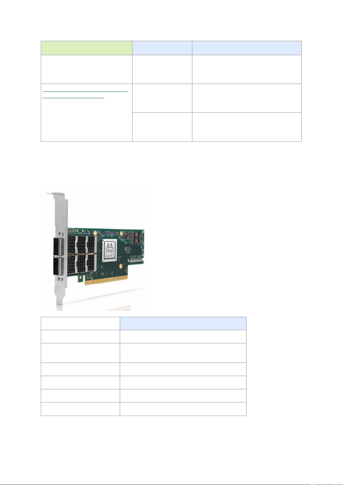
ConnectX-6 PCIe x16 Card
ConnectX-6 with a single PCIe x16 slot can support a bandwidth of up to 100Gb/s in a PCIe Gen 3.0 slot,
or up to 200Gb/s in a PCIe Gen 4.0 slot.
Part Number MCX653105A-
ECAT
Form Factor/Dimensions PCIe Half Height, Half Length / 167.65mm x 68.90mm
Data Transmission Rate Ethernet: 10/25/40/50/100 Gb/s
InfiniBand: SDR, DDR, QDR, FDR,
EDR, HDR100
Network Connector Type Single-port
QSFP56
PCIe x16 through Edge Connector PCIe Gen 3.0 / 4.0 SERDES @ 8.0GT/s / 16.0GT/s
RoHS RoHS Compliant
Adapter IC Part Number MT28908A0-XCCF-HVM
MCX653106AECAT
Dual-port
QSFP56
MCX653105AHDAT
Ethernet: 10/25/40/50/100/200 Gb/s
InfiniBand: SDR, DDR, QDR, FDR,
EDR, HDR100, HDR
Single-port
QSFP56
MCX653106AHDAT
Dual-port QSFP56
ConnectX-6 Socket Direct™ Cards
The Socket Direct technology offers improved performance to dual-socket servers by enabling
direct access from each CPU in a dual-socket server to the network through its dedicated PCIe
interface.
Please note thatConnectX-6 Socket Direct cards do not support Multi-Host functionality (i.e.
connectivity to two independent CPUs). For ConnectX-6 Socket Direct card with Multi-Host
functionality, please contact Mellanox.
Page 12
12
ConnectX-6 Socket Direct cards are available in two configurations: Dual-slot Configuration (2x PCIe
x16) and Single-slot Configuration (2x PCIe x8).
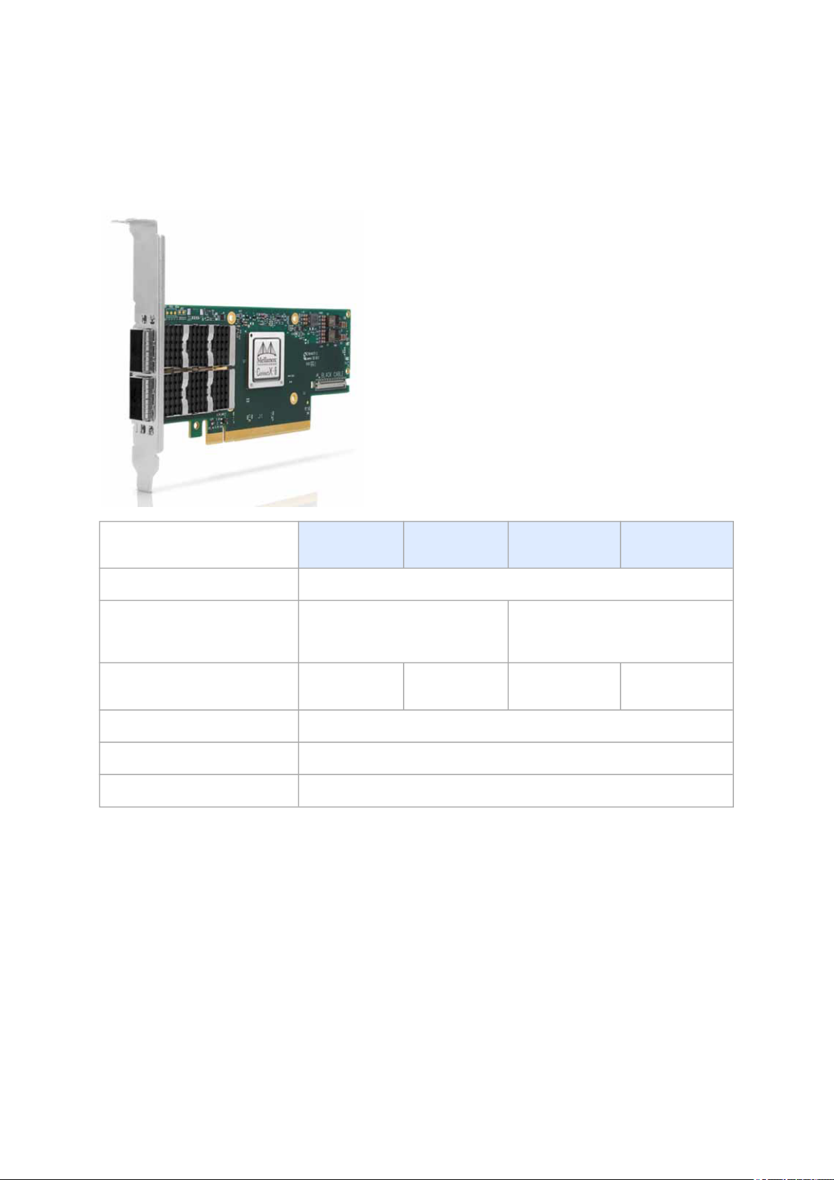
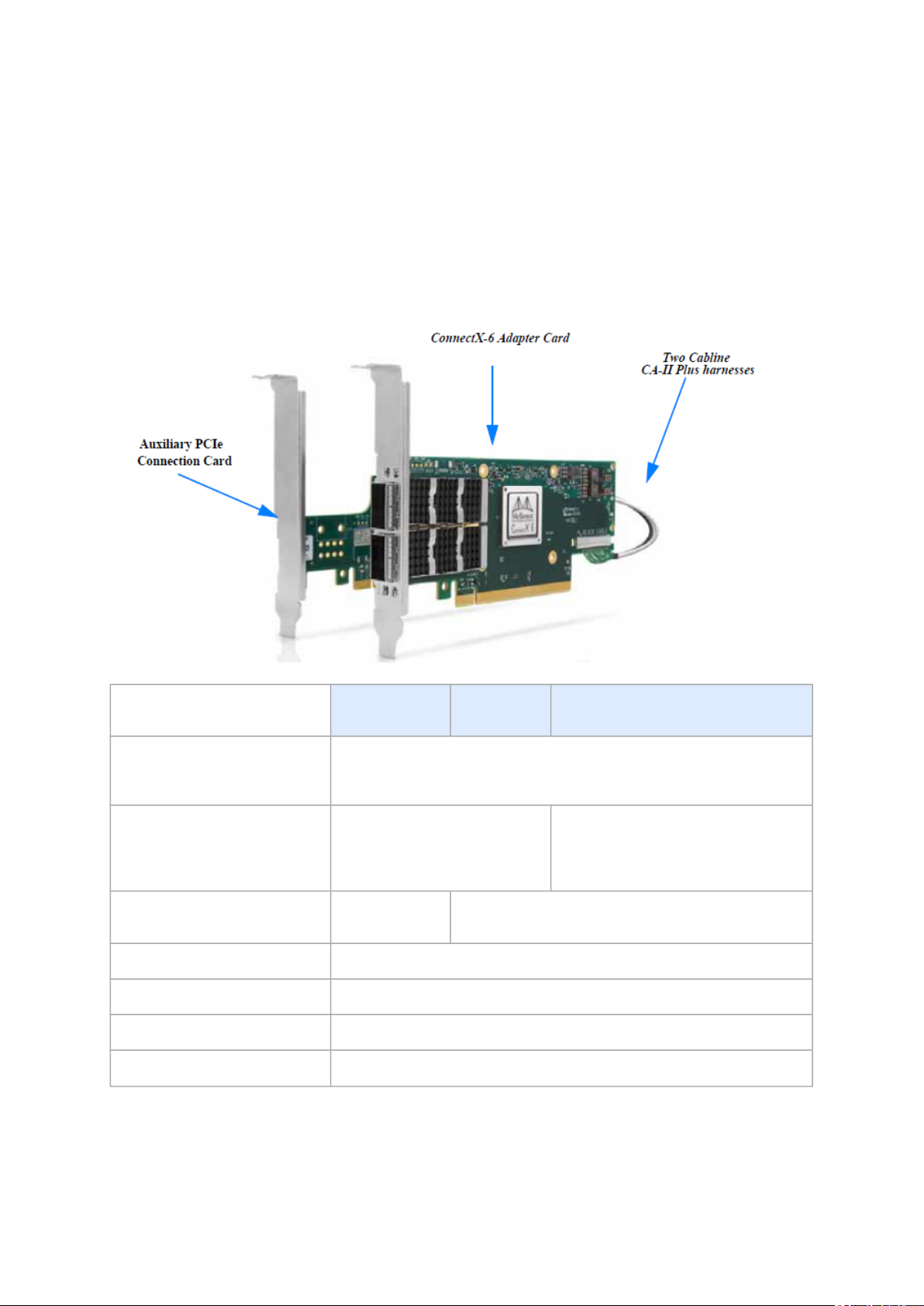
ConnectX-6 Dual-slot Socket Direct Cards (2x PCIe x16)
In order to obtain 200Gb/s speed, Mellanox offers ConnectX-6 Socket Direct that enable 200Gb/s
connectivity also for servers with PCIe Gen 3.0 capability. The adapter’s 32-lane PCIe bus is split into
two 16-lane buses, with one bus accessible through a PCIe x16 edge connector and the other bus
through an x16 Auxiliary PCIe Connection card. The two cards should be installed into two PCIe x16
slots and connected using two Cabline SA-II Plus harnesses, as shown in the below figure.
Part Number MCX654105A-
HCAT
Form Factor/Dimensions Adapter Card: PCIe Half Height, Half Length / 167.65mm x 68.90mm
Auxiliary PCIe Connection Card: 5.09 in. x 2.32 in. (129.30mm x 59.00mm)
Two 35cm Cabline CA-II Plus harnesses
Data Transmission Rate Ethernet: 10/25/40/50/100/200
Gb/s
InfiniBand: SDR, DDR, QDR, FDR,
EDR, HDR100, HDR
Network Connector Type Single-port
QSFP56
PCIe x16 through Edge Connector PCIe Gen 3.0 / 4.0SERDES@ 8.0GT/s / 16.0GT/s
PCIe x16 through Auxiliary Card PCIe Gen 3.0SERDES@ 8.0GT/s
RoHS RoHS Compliant
Adapter IC Part Number MT28908A0-XCCF-HVM
MCX654106AHCAT
Dual-port QSFP56
MCX654106A-ECAT
Ethernet: 10/25/40/50/100 Gb/s
InfiniBand: SDR, DDR, QDR, FDR, EDR,
HDR100
Page 13
13
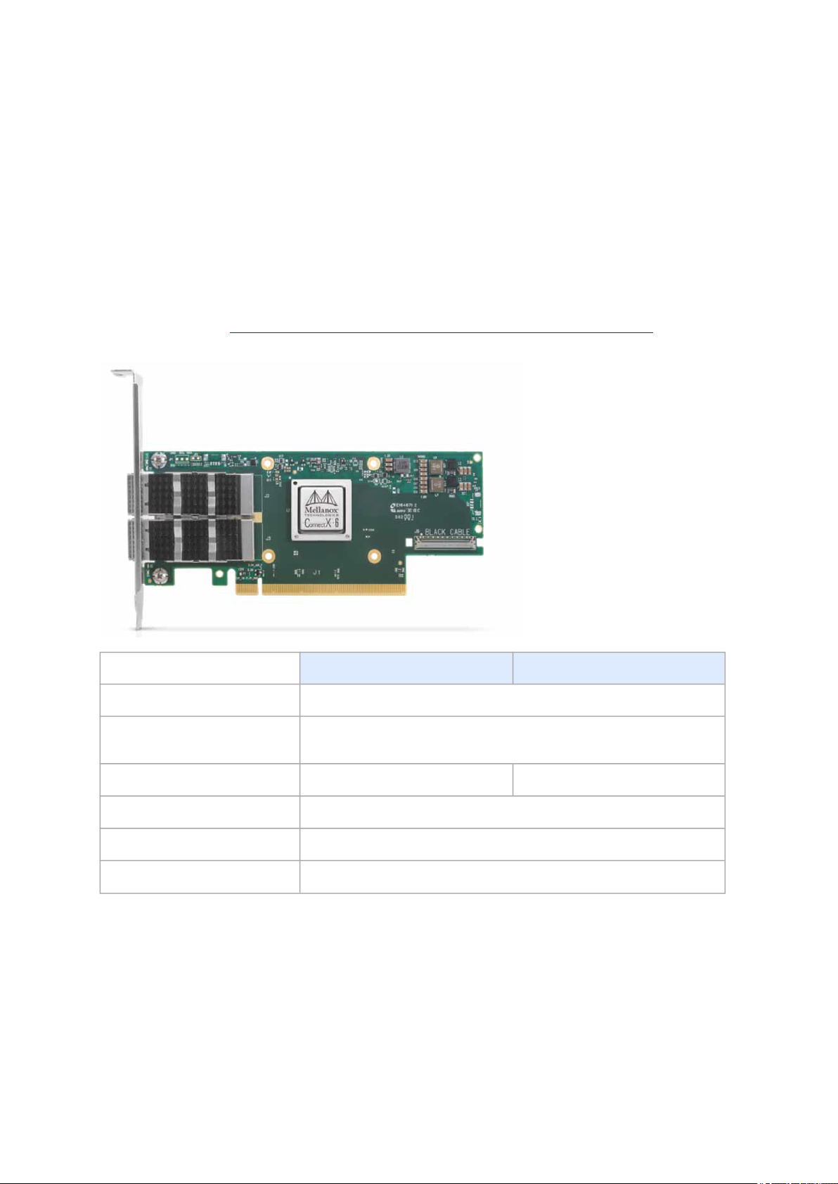
ConnectX-6 Single-slot Socket Direct Cards (2x PCIe x8 in a row)
The PCIe x16 interface comprises two PCIe x8 in a row, such that each of the PCIe x8 lanes can be
connected to a dedicated CPU in a dual-socket server. In such a configuration, Socket Direct brings
lower latency and lower CPU utilization as the direct connection from each CPU to the network means
the interconnect can bypass a QPI (UPI) and the other CPU, optimizing performance and improving
latency. CPU utilization is improved as each CPU handles only its own traffic and not traffic from the
other CPU.
A system with a custom PCI Express x16 slot that includes special signals is required for installing the
card. Please refer toPCIe Express Pinouts Description for Single-Slot Socket Direct Cardfor pinout
definitions.
Part Number MCX653105A-EFAT MCX653106A-EFAT
Form Factor/Dimensions PCIe Half Height, Half Length / 167.65mm x 68.90mm
Data Transmission Rate Ethernet: 10/25/40/50/100 Gb/s
InfiniBand: SDR, DDR, QDR, FDR, EDR, HDR100
Network Connector Type Single-port QSFP56 Dual-port QSFP56
PCIe x16 through Edge Connector PCIe Gen 3.0 / 4.0 SERDES @ 8.0GT/s / 16.0GT/s Socket Direct 2x8 in a row
RoHS RoHS Compliant
Adapter IC Part Number MT28908A0-XCCF-HVM
Page 14

14
Package Contents
ConnectX-6 PCIe x8/x16 Adapter Cards
Applies to MCX651105A-EDAT, MCX653105A-ECAT, MCX653106A-ECAT, MCX653105A-HDAT,
MCX653106A-HDAT, MCX653105A-EFAT, MCX653106A-EFAT.
Category Qty Item
Cards 1 ConnectX-6 adapter card
Accessories 1 Adapter card short bracket
1 Adapter card tall bracket (shipped assembled on the
card)
ConnectX-6 Socket Direct Cards (2x PCIe x16)
Applies to MCX654105A-HCAT, MCX654106A-HCAT and MCX654106A-ECAT.
Category Qty. Item
Cards 1 ConnectX-6 adapter card
1 PCIe Auxiliary Card
Harnesses 1 35cm Cabline CA-II Plus harness (white)
1 35cm Cabline CA-II Plus harness (black)
2 Retention Clip for Cablline harness (optional accessory)
1 Adapter card short bracket
Accessories
1 Adapter card tall bracket (shipped assembled on the
card)
1 PCIe Auxiliary card short bracket
1 PCIe Auxiliary card tall bracket (shipped assembled on
the card)
Page 15

15
Features and Benefits
Make sure to use a PCIe slot that is capable of supplying the required power and airflow to the
ConnectX-6 cards as stated in Specifications.
PCI
Express
(PCIe)
200Gb/s
Virtual
Protocol
Interconne
ct (VPI)
Adapter
InfiniBand
Architectu
re
Specificati
on v1.3
compliant
Up to 200
Gigabit
Ethernet
Uses the following PCIe interfaces:
•
PCIe x8/x16 configurations:
PCIe Gen 3.0 (8GT/s) and Gen 4.0 (16GT/s) through an x8/x16 edge connector.
•
2x PCIe x16 configurations:
PCIe Gen 3.0/4.0 SERDES @ 8.0/16.0 GT/s through Edge Connector
PCIe Gen 3.0 SERDES @ 8.0GT/s through PCIe Auxiliary Connection Card
ConnectX-6 offers the highest throughput VPI adapter, supporting HDR 200b/s InfiniBand and
200Gb/s Ethernet and enabling any standard networking, clustering, or storage to operate
seamlessly over any converged network leveraging a consolidated software stack.
ConnectX-6 delivers low latency, high bandwidth, and computing efficiency for performance-driven
server and storage clustering applications. ConnectX-6 is InfiniBand Architecture Specification
v1.3 compliant.
Mellanox adapters comply with the following IEEE 802.3 standards:
200GbE / 100GbE / 50GbE / 40GbE / 25GbE / 10GbE / 1GbE
- IEEE 802.3bj, 802.3bm 100 Gigabit Ethernet
- IEEE 802.3by, Ethernet Consortium25, 50 Gigabit Ethernet, supporting all FEC modes
- IEEE 802.3ba 40 Gigabit Ethernet
- IEEE 802.3by 25 Gigabit Ethernet
- IEEE 802.3ae 10 Gigabit Ethernet
- IEEE 802.3ap based auto-negotiation and KR startup
- IEEE 802.3ad, 802.1AX Link Aggregation
- IEEE 802.1Q, 802.1P VLAN tags and priority
- IEEE 802.1Qau (QCN)
- Congestion Notification
- IEEE 802.1Qaz (ETS)
- IEEE 802.1Qbb (PFC)
- IEEE 802.1Qbg
- IEEE 1588v2
- Jumbo frame support (9.6KB)
InfiniBand
HDR100
InfiniBand
HDR
Memory
Componen
ts
A standard InfiniBand data rate, where each lane of a 2X port runs a bit rate of 53.125Gb/s with a
64b/66b encoding, resulting in an effective bandwidth of 100Gb/s.
A standard InfiniBand data rate, where each lane of a 4X port runs a bit rate of 53.125Gb/s with a
64b/66b encoding, resulting in an effective bandwidth of 200Gb/s.
•
SPI Quad - includes 256Mbit SPI Quad Flash device (MX25L25645GXDI-08G device by
Macronix)
•
FRU EEPROM - Stores the parameters and personality of the card. The EEPROM capacity is
128Kbit. FRU I2C address is (0x50) and is accessible through the PCIe SMBus.
Page 16

16
Overlay
Networks
In order to better scale their networks, datacenter operators often create overlay networks that
carry traffic from individual virtual machines over logical tunnels in encapsulated formats such as
NVGRE and VXLAN. While this solves network scalability issues, it hides the TCP packet from the
hardware offloading engines, placing higher loads on the host CPU. ConnectX-6 effectively
addresses this by providing advanced NVGRE and VXLAN hardware offloading engines that
encapsulate and de-capsulate the overlay protocol.
RDMA and
RDMA over
Converged
Ethernet
(RoCE)
Mellanox
PeerDirect
™
CPU
Offload
Quality of
Service
(QoS)
Hardwarebased I/O
Virtualizati
on
Storage
Accelerati
on
ConnectX-6, utilizing IBTA RDMA (Remote Data Memory Access) and RoCE (RDMA over Converged
Ethernet) technology, delivers low-latency and high-performance over InfiniBand and Ethernet
networks. Leveraging datacenter bridging (DCB) capabilities as well as ConnectX-6 advanced
congestion control hardware mechanisms, RoCE provides efficient low-latency RDMA services
over Layer 2 and Layer 3 networks.
PeerDirect™ communication provides high efficiency RDMA access by eliminating unnecessary
internal data copies between components on the PCIe bus (for example, from GPU to CPU), and
therefore significantly reduces application run time. ConnectX-6 advanced acceleration technology
enables higher cluster efficiency and scalability to tens of thousands of nodes.
Adapter functionality enabling reduced CPU overhead allowing more available CPU for
computation tasks.
•
Flexible match-action flow tables
•
Open VSwitch (OVS) offload using ASAP2(TM)
•
Tunneling encapsulation / decapsulation
Support for port-based Quality of Service enabling various application requirements for latency
and SLA.
ConnectX-6 provides dedicated adapter resources and guaranteed isolation and protection for
virtual machines within the server.
A consolidated compute and storage network achieves significant cost-performance advantages
over multi-fabric networks. Standard block and file access protocols can leverage:
•
RDMA for high-performance storage access
•
NVMe over Fabric offloads for target machine
•
Erasure Coding
•
T10-DIF Signature Handover
SR-IOV ConnectX-6 SR-IOV technology provides dedicated adapter resources and guaranteed isolation and
protection for virtual machines (VM) within the server.
HighPerforman
ce
Accelerati
ons
•
Tag Matching and Rendezvous Offloads
•
Adaptive Routing on Reliable Transport
•
Burst Buffer Offloads for Background Checkpointing
Page 17

17
Operating Systems/Distributions
ConnectX-6 Socket Direct cards 2x PCIe x16 (OPNs: MCX654105A-HCAT, MCX654106A-HCAT
and MCX654106A-ECAT) are not supported in Windows and WinOF-2.
•
OpenFabrics Enterprise Distribution (OFED)
•
RHEL/CentOS
•
Windows
•
FreeBSD
•
VMware
•
OpenFabrics Enterprise Distribution (OFED)
•
OpenFabrics Windows Distribution (WinOF-2)
Connectivity
•
Interoperable with 1/10/25/40/50/100/200 Gb/s InfiniBand/VPI and Ethernet switches
•
Passive copper cable with ESD protection
•
Powered connectors for optical and active cable support
Manageability
ConnectX-6 technology maintains support for manageability through a BMC. ConnectX-6 PCIe stand-up
adapter can be connected to a BMC using MCTP over SMBus or MCTP over PCIe protocols as if it is a
standard Mellanox PCIe stand-up adapter. For configuring the adapter for the specific manageability
solution in use by the server, please contact Mellanox Support.
Page 18

18
Interfaces
InfiniBand Interface
The network ports of the ConnectX®-6 adapter cards are compliant with the
Specification, Release 1.3.
InfiniBand traffic is transmitted through the cards' QSFP56 connectors.
InfiniBand Architecture
Ethernet QSFP56 Interfaces
The adapter card includes special circuits to protect from ESD shocks to the card/server when
plugging copper cables.
The network ports of the ConnectX-6 adapter card are compliant with the IEEE 802.3 Ethernet
standards listed in Features and Benefits. Ethernet traffic is transmitted through the QSFP56
connectors on the adaptercard.
PCI Express Interface
ConnectX®-6 adapter cards support PCI Express Gen 3.0/4.0 (1.1 and 2.0 compatible) through x8/x16
edge connectors. The device can be either a master initiating the PCI Express bus operations, or a
slave responding to PCI bus operations.
The following lists PCIe interface features:
•
PCIe Gen 3.0 and 4.0 compliant, 2.0 and 1.1 compatible
•
2.5, 5.0, 8.0, or 16.0 GT/s link rate x16/x32
•
Auto-negotiates to x32, x16, x8, x4, x2, or x1
•
Support for MSI/MSI-X mechanisms
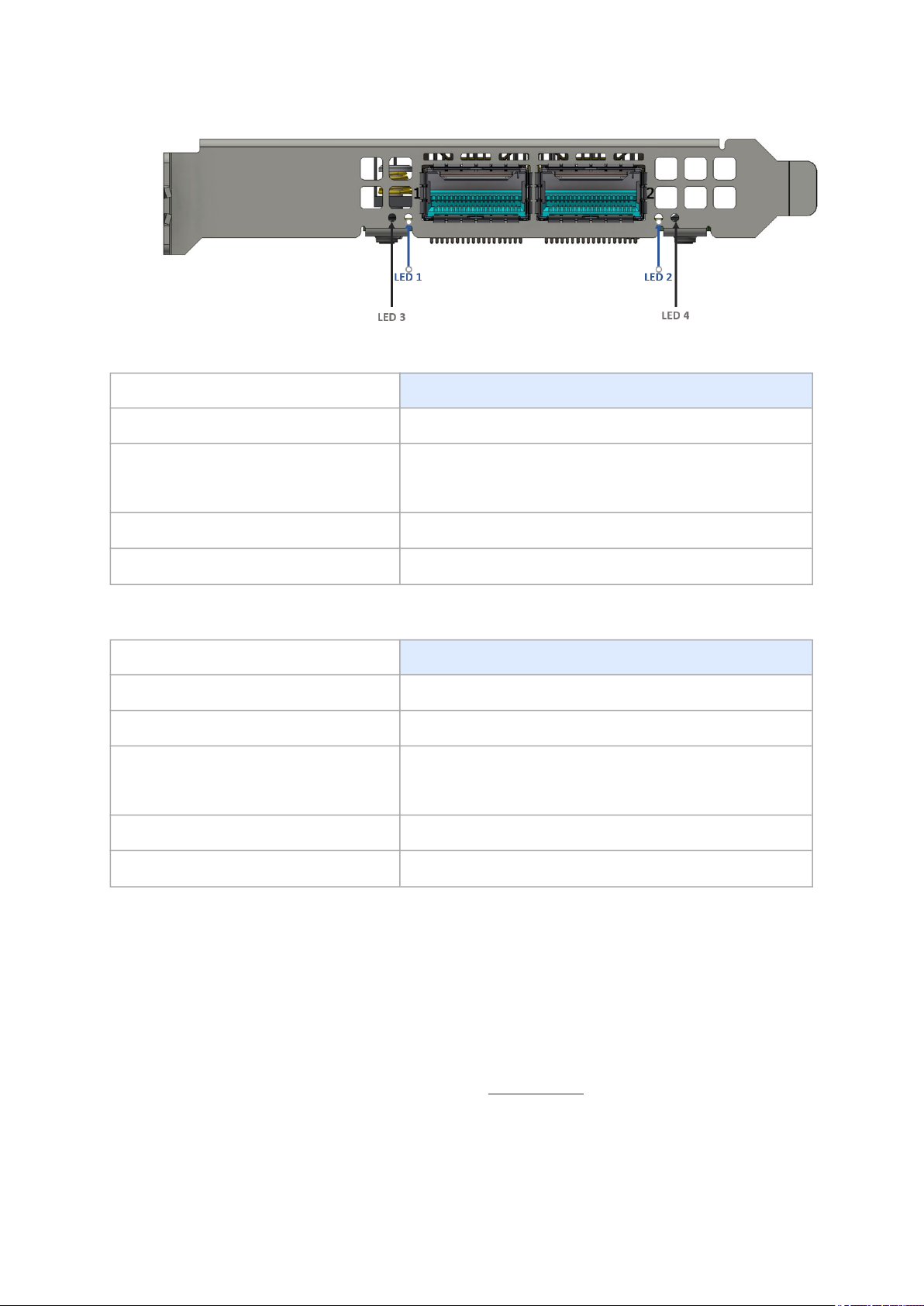
LED Interface
The adapter card includes special circuits to protect from ESD shocks to the card/server when
plugging copper cables.
There are two I/O LEDs per port:
•
LED 1 and 2: Bi-color I/O LED which indicates link status. LED behavior is described below for
Ethernet and InfiniBand port configurations.
Page 19
19
• LED 3 and 4: Reserved for future use.
LED1 and LED2 Link Status Indications (Physical and Logical) - Ethernet Protocole:
LED Color and State Description
Off A link has not been established
Blinking amber 1 Hz Blinking amber occurs due to running a beacon command
for locating the adapter card
4 Hz blinking amber indicates a problem with the physical link
Solid green Indicates a valid link with no active traffic
Blinking green Indicates a valid logical link with active traffic
LED1 and LED2Link Status Indications(Physical and Logical) - InfiniBand Protocole:
LED Color and State Description
Off A physical link has not been established
Solid amber Indicates an active physical link
Blinking amber 1 Hz Blinking amber occurs due to running a beacon command
for locating the adapter card
4 Hz blinking amber indicates a problem with the physical link
Solid green Indicates a valid logical (data activity) link with no active traffic
Blinking green Indicates a valid logical link with active traffic
Heat Sink Interface
The heatsink is attached to the ConnectX-6 IC in order to dissipate the heat from the ConnectX-6 IC. It
is attached either by using four spring-loaded push pins that insert into four mounting holes, or by
screws.
ConnectX-6 IC has a thermal shutdown safety mechanism which automatically shuts down the
ConnectX-6 card in cases of high-temperature event, improper thermal coupling or heatsink removal.
For the required airflow (LFM) per OPN, please refer toSpecifications.
Page 20

20
SMBus Interface
ConnectX-6 technology maintains support for manageability through a BMC. ConnectX-6 PCIe stand-up
adapter can be connected to a BMC using MCTP over SMBus or MCTP over PCIe protocols as if it is a
standard Mellanox PCIe stand-up adapter. For configuring the adapter for the specific manageability
solution in use by the server, please contact Mellanox Support.
Voltage Regulators
The voltage regulator power is derived from the PCI Express edge connector 12V supply pins. These
voltage supply pins feed on-board regulators that provide the necessary power to the various
components on the card.
Page 21
21
Hardware Installation
Installation and initialization of ConnectX-6 adapter cards require attention to the mechanical
attributes, power specification, and precautions for electronic equipment.
Safety Warnings
Safety warnings are provided here in the English language. For safety warnings in other
languages, refer to the Adapter Installation Safety Instructions document available on
mellanox.com.
Please observe all safety warnings to avoidinjury and prevent damage to system components. Note
that not all warnings are relevant to all models.
Unable to render include or excerpt-include. Could not retrieve page.
Installation Procedure Overview
The installation procedure of ConnectX-6 adapter cards involves the following steps:
Step Procedure Direct Link
1 Check the system’s hardware and software
requirements.
2 Pay attention to the airflow consideration within
the host system
3 Follow the safety precautions Safety Precautions
4 Unpack the package Unpack the package
5 Follow the pre-installation checklist Pre-Installation Checklist
6 (Optional) Replace the full-height mounting
bracket with the supplied short bracket
7 Install the ConnectX-6 PCIe x8/x16 adapter card
in the system
Install the ConnectX-6 2x PCIe x16 Socket Direct
adapter card in the system
8 Connect cables or modules to the card Cables and Modules
9 Identify ConnectX-6 in the system Identifying Your Card
System Requirements
Airflow Requirements
Bracket Replacement Instructions
ConnectX-6 PCIe x8/x16 Adapter Cards
Installation Instructions
ConnectX-6 Socket Direct (2x PCIe x16)
Installation Instructions
Page 22

22
System Requirements
Hardware Requirements
Unless otherwise specified, Mellanox products are designed to work in an environmentally
controlled data center with low levels of gaseous and dust (particulate) contamination.
The operating environment should meet severity level G1 as per ISA 71.04 for gaseous
contamination and ISO 14644-1 class 8 for cleanliness level.
For proper operation and performance, please make sure to use a PCIe slot with a
corresponding bus width and that can supply sufficient power to your card. Refer to the
Specifications section of the manual for more power requirements.
Please make sure to install the ConnectX-6 cards in a PCIe slot that is capable of supplying
the required power as statedin Specifications.
ConnectX-6 Configuration Hardware Requirements
PCIe x8/x16 A system with a PCI Express x8/x16 slot is required for
installing the card.
Socket Direct 2x PCIe x8 in a row (single slot) A system with a custom PCI Express x16 slot (four special
pins) is required for installing the card. Please refer to PCIe
Express Pinouts Description for Single-Slot Socket Direct
Card for pinout definitions.
Socket Direct 2x PCIe x16 (dual slots) A system with two PCIe x16 slots is required for installing the
cards.
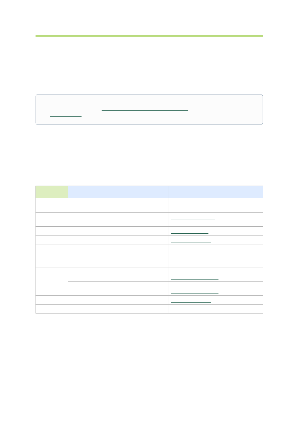
Airflow Requirements
ConnectX-6 adapter cards are offered with two airflow patterns: from the heatsink to the network
ports, and vice versa, as shown below.
Please refer to the Specificationssection for airflow numbers for each specific card model.
Airflow
fromthe heatsink
to the network ports:
Page 23
23
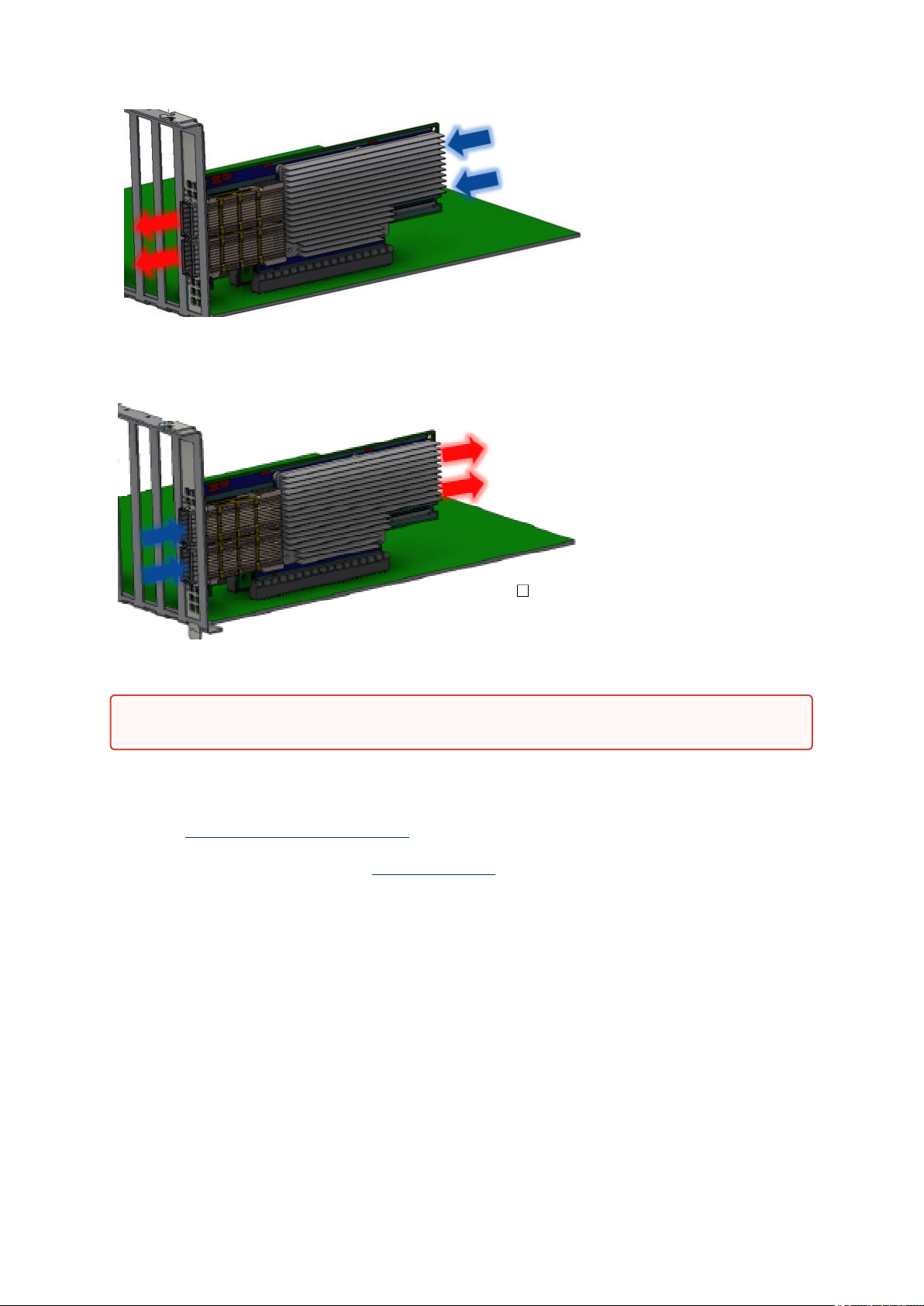
Airflow
from the network ports
All cards in the system should be planned with the same airflow direction.
to the heatsink:
Software Requirements
•
See Operating Systems/Distributionssection under the Introduction section.
•
Software Stacks - Mellanox OpenFabric software package MLNX_OFED for Linux, WinOF-2 for
Windows, and VMware. See the Driver Installationsection.
Safety Precautions
The adapter is being installed in a system that operates with voltages that can be lethal. Before
opening the case of the system, observe the following precautions to avoid injury and prevent damage
to system components.
•
Remove any metallic objects from your hands and wrists.
•
Make sure to use only insulated tools.
•
Verify that the system is powered off and is unplugged.
•
It is strongly recommended to use an ESD strap or other antistatic devices.
Page 24

24
Pre-Installation Checklist
•
Unpack the ConnectX-6 Card; Unpack and remove the ConnectX-6 card. Check against the
package contents list that all the parts have been sent. Check the parts for visible damage that
may have occurred during shipping. Please note that the cards must be placed on an antistatic
surface. For package contents please refer toPackage Contents.
Please note that if the card is removed hastily from the antistatic bag, the plastic
ziplock may harm the EMI fingers on the networking connector. Carefully remove the
card from the antistatic bag to avoid damaging the EMI fingers.
•
Shut down your system if active;Turn off the power to the system, and disconnect the power
cord. Refer to the system documentation for instructions. Before you install the ConnectX-6
card, make sure that the system is disconnected from power.
•
(Optional) Check the mounting bracket on the ConnectX-6 or PCIe Auxiliary Connection Card;If
required for your system, replace the full-height mounting bracket that is shipped mounted on
the card with the supplied low-profile bracket. Refer to Bracket Replacement Instructions
.
Bracket Replacement Instructions
The ConnectX-6 card and PCIe Auxiliary Connection card are usually shipped with an assembled highprofile bracket. If this form factor is suitable for your requirements, you can skip the remainder of this
section and move toInstallation Instructions. If you need to replace the high-profile bracket with the
short bracket that is included in the shipping box, please follow the instructions in this section.
Due to risk of damaging the EMI gasket, it is not recommended to replace the bracket more
than three times.
To replace the bracket you will need the following parts:
•
The new brackets of the proper height
•
The 2 screws saved from the removal of the bracket
Removing the Existing Bracket
1.
Using a torque driver, remove the two screws holding the bracket in place.
2.
Separate the bracket from the ConnectX-6 card.
Be careful not to put stress on the LEDs on the adapter card.
3.
Save the two screws.
Installing the New Bracket
1.
Place the bracket onto the card until the screw holes line up.
Do not force the bracket onto the adapter card.
2.
Screw on the bracket using the screws saved from the bracket removal procedure above.
Page 25

25
Use a torque driver to apply up to 2 lbs-in torque on the screws.
Installation Instructions
This section provides detailed instructions on how to install your adapter card in a system.
Choose the installation instructions according to the ConnectX-6 configuration you have purchased.
OPNs Installation Instructions
MCX651105A-EDAT
MCX653105A-HDAT
MCX653106A-HDAT
MCX653105A-ECAT
MCX653106A-ECAT
MCX653105A-EFAT
MCX653106A-EFAT
MCX654105A-HCAT
MCX654106A-HCAT
MCX654106A-ECAT
ConnectX-6 (PCIe x8/x16) Adapter Card
ConnectX-6 Socket Direct (2x PCIe x16) Adapter Card
Cables and Modules
To obtain the list of supported Mellanox cables for your adapter, please refer to theCables Reference
Tableathttp://www.mellanox.com/products/interconnect/cables-configurator.php.
Cable Installation
1.
All cables can be inserted or removed with the unit powered on.
2.
To insert a cable, press the connector into the port receptacle until the connector is firmly
seated.
a.
Support the weight of the cable before connecting the cable to the adapter card. Do this
by using a cable holder or tying the cable to the rack.
b.
Determine the correct orientation of the connector to the card before inserting the
connector. Do not try and insert the connector upside down. This may damage the
adapter card.
c.
Insert the connector into the adapter card. Be careful to insert the connector straight into
the cage. Do not apply any torque, up or down, to the connector cage in the adapter card.
d.
Make sure that the connector locks in place.
When installing cables make sure that the latches engage.
Always install and remove cables by pushing or pulling the cable and connector
in a straight line with the card.
3.
After inserting a cable into a port, the Green LED indicator will light when the physical
connection is established (that is, when the unit is powered on and a cable is plugged into the
port with the other end of the connector plugged into a functioning port).See LED
Interfaceunder the Interfaces section.
Page 26

26
4.
[root@mftqa-009 ~]# lspci |grep mellanox -i
a3:00.0 Infiniband controller: Mellanox Technologies MT28908 Family [ConnectX-6]
e3:00.0 Infiniband controller: Mellanox Technologies MT28908 Family [ConnectX-6]
[root@mftqa-009 ~]# lspci |grep mellanox -i
05:00.0 Infiniband controller: Mellanox Technologies MT28908A0 Family [ConnectX-6]
05:00.1 Infiniband controller: Mellanox Technologies MT28908A0 Family [ConnectX-6]
82:00.0 Infiniband controller: Mellanox Technologies MT28908A0 Family [ConnectX-6]
82:00.1 Infiniband controller: Mellanox Technologies MT28908A0 Family [ConnectX-6]
[root@mftqa-009 ~]# lspci |grep mellanox -i
3:00.0 Infiniband controller: Mellanox Technologies MT28908 Family [ConnectX-6]
[root@mftqa-009 ~]# lspci |grep mellanox -i
86:00.0 Network controller: Mellanox Technologies MT28908A0 Family [ConnectX-6] 86:00.1
Network controller: Mellanox Technologies MT28908A0 Family [ConnectX-6]
After plugging in a cable, lock the connector using the latching mechanism particular to the
cable vendor. When data is being transferred the Green LED will blink. See LED Interfaceunder
the Interfaces section.
5.
Care should be taken as not to impede the air exhaust flow through the ventilation holes. Use
cable lengths which allow for routing horizontally around to the side of the chassis before
bending upward or downward in the rack.
6.
To remove a cable, disengage the locks and slowly pull the connector away from the port
receptacle. LED indicator will turn off when the cable is unseated.
Identifying the Card in Your System
On Linux
Get the device location on the PCI bus by running lspci and locating lines with the string“Mellanox
Technologies”:
ConnectX-6 Card
Configuration
Single-port Socket
Direct Card (2x PCIe
x16)
Dual-port Socket
Direct Card (2x PCIe
x16)
Single-port PCIe x8/
x16 Card
lspci Command Output Example
Intheoutput exampleabove, thefirst
tworowsindicatethatonecardisinstalledinaPCIslotwithPCIBusaddress05
(hexadecimal),PCIDevicenumber00andPCIFunctionnumber0and1.Theother
cardisinstalledinaPCIslotwithPCIBusaddress82(hexa-decimal),PCIDevicenumb
er00andPCIFunctionnumber0and1.
Sincethetwo PCIecards are installed intwo PCIe slots,eachcard
getsauniquePCIBusandDevicenumber.EachofthePCIex16bussesseestwonetwork
ports;ineffect,thetwo physicalportsoftheConnectX-6SocketDirectadapterareviewe
dasfournet devicesbythesystem.
Dual-port PCIe x16
Card
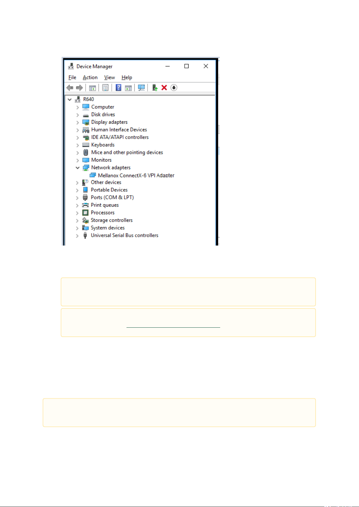
On Windows
1.
Open Device Manager on the server. ClickStart=>Run, and then enterdevmgmt.msc.
2.
ExpandSystem Devicesand locate your Mellanox ConnectX-6 adapter card.
3.
Right click the mouse on your adapter's row and selectPropertiesto display the adapter card
properties window.
4.
Click theDetailstab and selectHardware Ids(Windows 2012/R2/2016) from thePropertypull-
down menu.
Page 27
27
PCI Device (Example)
5.
In theValuedisplay box, check the fields VEN and DEV (fields are separated by ‘&’). In the
display example above, notice the sub-string “PCI\VEN_15B3&DEV_1003”: VEN is equal to
0x15B3 – this is the Vendor ID of Mellanox Technologies; and DEV is equal to 1018 (for
ConnectX-6) – this is a valid Mellanox Technologies PCI Device ID.
If the PCI device does not have a Mellanox adapter ID, return to Step 2 to check
another device.
The list of Mellanox Technologies PCI Device IDs can be found in the PCI ID
repository at http://pci-ids.ucw.cz/read/PC/15b3.
ConnectX-6 PCIe x8/16 Installation Instructions
Installing the Card
Applies to MCX651105A-EDAT, MCX654105A-HCAT, MCX654106A-HCAT and MCX654106A-
ECAT.
Page 28

28
Please make sure to install the ConnectX-6 cards in a PCIe slot that is capable of supplying
the required power and airflow as stated in Specifications.
Connect the adapter Card in an available PCI Express x16 slot in the chassis.
Step 1:Locate an available PCI Express x16 slot and insert the adapter card to the chassis.
Step 2:Applying even pressure at both corners of the card, insert the adapter card in a PCI
Express slot until firmly seated.
Do not use excessive force when seating the card, as this may damage the chassis.
Secure the adapter card to the chassis.
Step 1:Securethebrackettothechassiswiththebracketscrew.
Page 29

29
Uninstalling the Card
Safety Precautions
The adapter is installed in a system that operates with voltages that can be lethal. Before uninstalling
the adapter card, please observe the following precautions to avoid injury and prevent damage to
system components.
1.
Remove any metallic objects from your hands and wrists.
2.
It is strongly recommended to use an ESD strap or other antistatic devices.
3.
Turn off the system and disconnect the power cord from the server.
Card Removal
Please note that the following images are for illustration purposes only.
1.
Verify that the system is powered off and unplugged.
2.
Wait 30 seconds.
3.
To remove the card, disengage the retention mechanisms on the bracket (clips or screws).
Page 30

30
4. Holding the adapter card from its center, gently pull the ConnectX-6 and Auxiliary Connections
cards out of the PCI Express slot.
ConnectX-6 Socket Direct (2x PCIe x16) Installation Instructions
The hardware installation section uses the terminology of white and black harnesses to differentiate
between the two supplied cables. Due to supply chain variations, some cards may be supplied with two
black harnesses instead. To clarify the difference between these two harnesses, one black harness
was marked with a “WHITE” label and the other with a “BLACK” label.
Page 31

31
The Cabline harness marked with "WHITE" label should be connected to the connector on the
ConnectX-6 and PCIe card engraved with “White Cable” while the one marked with"BLACK" label
should be connected to the connector on the ConnectX-6 and PCIe card engraved with “Black Cable”.
The harnesses' minimal bending radius is 10[mm].
Installing the Card
Applies to MCX654105A-HCAT, MCX654106A-HCAT and MCX654106A-ECAT.
The installation instructions include steps that involve a retention clip to be used while
connecting the Cabline harnesses to the cards. Please note that this is an optional accessory.
Please make sure to install the ConnectX-6 cards in a PCIe slot that is capable of supplying
the required power and airflow as stated in Specifications.
Connect the adapter card with the Auxiliary connection card using the supplied Cabline CA-II
Plus harnesses.
Step 1:Slide the black and white Cabline CA-II Plus harnesses through the retention clip while
making sure the clip opening is facing the plugs.
Step 2:Plug the Cabline CA-II Plus harnesses on the ConnectX-6 adapter card while paying
attention to the color-coding. As indicated on both sides of the card; plug the black harness to the
component side and the white harness to the print side.
Page 32

32
Step 2:Verify the plugs are locked.
Step 3:Slide the retention clip latches through the cutouts on the PCB. The latches should face
the annotation on the PCB.
Page 33

33
Step 4:Clamp the retention clip. Verify both latches are firmly locked.
Step 5:Slide theCabline CA-II Plus harnesses through the retention clip. Make sure that the clip
opening is facing the plugs.
Page 34

34
Step 6:Plug the Cabline CA-II Plus harnesses on the PCIe Auxiliary Card. As indicated on
bothsides of the Auxiliary connection card; plug the black harness to the component side and
thewhite harness to the print side.
Step 7:Verify the plugs are locked.
Step 8:Slide the retention clip through the cutouts on the PCB. Make sure latches are facing
"Black Cable" annotation as seen in the below picture.
Page 35

35
Step 9:Clamp the retention clip. Verify both latches are firmly locked.
Connect the ConnectX-6 adapter and PCIe Auxiliary Connection cards in available PCI Express
x16 slots in the chassis.
Step 1:Locate two available PCI Express x16 slots.
Step 2:Applying even pressure at both corners of the cards, insert the adapter card in the
PCIExpress slots until firmly seated.
Page 36

36
Secure the ConnectX-6 adapter and PCIe Auxiliary Connection Cards to the chassis.
Do not use excessive force when seating the cards, as this may damage the system or
the cards.
Step 3:Applying even pressure at both corners of the cards, insert the Auxiliary Connection card
inthe PCI Express slots until firmly seated.
Step 1:Secure the brackets to the chassis with the bracket screw.
Page 37

37
Uninstalling the Card
Safety Precautions
The adapter is installed in a system that operates with voltages that can be lethal. Before uninstalling
the adapter card, please observe the following precautions to avoid injury and prevent damage to
system components.
1.
Remove any metallic objects from your hands and wrists.
2.
It is strongly recommended to use an ESD strap or other antistatic devices.
3.
Turn off the system and disconnect the power cord from the server.
Card Removal
Please note that the following images are for illustration purposes only.
1.
Verify that the system is powered off and unplugged.
2.
Wait 30 seconds.
3.
To remove the card, disengage the retention mechanisms on the bracket (clips or screws).
Page 38

38
4. Holding the adapter card from its center, gently pull the ConnectX-6 and Auxiliary Connections
cards out of the PCI Express slot.
Page 39

39
Driver Installation
Please use the relevant driver installation section.
ConnectX-6 Socket Direct cards 2x PCIe x16 (OPNs: MCX654106A-HCAT andMCX654106A-
ECAT) are not supported inWindows and WinOF-2.
•
Linux Driver Installation
•
Windows Driver Installation
•
VMware Driver Installation
Linux Driver Installation
This section describes how to install and test the Mellanox OFED for Linux package on a single server
with a Mellanox ConnectX-5 adapter card installed.
Prerequisites
Requirements Description
Platforms A server platform with a ConnectX-6 InfiniBand/VPI adapter
card installed.
Required Disk Space for Installation 1GB
Device ID For the latest list of device IDs, please visit the Mellanox
website athttp://www.mellanox.com/page/
firmware_HCA_FW_identification.
Operating System Linux operating system.
For the list of supported operating system distributions and
kernels, please refer to the
file.
InstallerPrivileges The installation requires administrator (root) privileges on
the target machine.
Mellanox OFED Release Notes
Downloading Mellanox OFED
1.
Verify that the system has a Mellanox network adapter installed by running lscpi command. The
below table provides output examples per ConnectX-6 card configuration.
Page 40

40
ConnectX-6 Card
[root@mftqa-009 ~]# lspci |grep mellanox -i
a3:00.0 Infiniband controller: Mellanox Technologies MT28908 Family
[ConnectX-6]
e3:00.0 Infiniband controller: Mellanox Technologies MT28908 Family
[ConnectX-6]
[root@mftqa-009 ~]# lspci |grep mellanox -i
05:00.0 Infiniband controller: Mellanox Technologies MT28908A0 Family
[ConnectX-6]
05:00.1 Infiniband controller: Mellanox Technologies MT28908A0 Family
[ConnectX-6]
82:00.0 Infiniband controller: Mellanox Technologies MT28908A0 Family
[ConnectX-6]
82:00.1 Infiniband controller: Mellanox Technologies MT28908A0 Family
[ConnectX-6]
[root@mftqa-009 ~]# lspci |grep mellanox -ia
3:00.0 Infiniband controller: Mellanox Technologies MT28908 Family [ConnectX-6]
[root@mftqa-009 ~]# lspci |grep mellanox -ia
86:00.0 Network controller: Mellanox Technologies MT28908A0 Family [ConnectX-6]
86:00.1 Network controller: Mellanox Technologies MT28908A0 Family [ConnectX-6]
md5sum MLNX_OFED_LINUX-<ver>-<OS label>.iso
Configuration
Single-port Socket
Direct Card (2x PCIe
x16)
Dual-port Socket
Direct Card (2x PCIe
x16)
Intheoutput exampleabove, thefirst
tworowsindicatethatonecardisinstalledinaPCIslotwithPCIBusaddress
05(hexadecimal),PCIDevicenumber00andPCIFunctionnumber0and1.
TheothercardisinstalledinaPCIslotwithPCIBusaddress82(hexadecimal),
PCIDevicenumber00andPCIFunctionnumber0and1.
Sincethetwo PCIecards are installed intwo PCIe slots,eachcard
getsauniquePCIBusandDevicenumber.EachofthePCIex16bussesseestwo
networkports;ineffect,thetwophysicalportsoftheConnectX-6SocketDirect
adapterareviewedasfournet devicesbythesystem.
Single-port PCIe x16
Card
Dual-port PCIe x16
Card
2.
Download the ISO image to your host.
The image’s name has the formatMLNX_OFED_LINUX-<ver>-<OS label><CPU arch>.iso.
You can download and install the latest OpenFabrics Enterprise Distribution (OFED) software
package available via the Mellanox web site athttp://www.mellanox.com> Products > Software
> Ethernet Drivers > Linux SW/Drivers > Download..
a.
Scroll down to the Download wizard, and click the Download tab.
b.
Choose your relevant package depending on your host operating system.
c.
Click the desired ISO/tgz package.
d.
To obtain the download link, accept the End User License Agreement (EULA).
3.
Use the md5sum utility to confirm the file integrity of your ISO image. Run the following
command and compare the result to the value provided on the download page.
Page 41

41
Installing Mellanox OFED
./mlnxofedinstall --fw-image-dir /tmp/my_fw_bin_files
./mnt/mlnxofedinstall [OPTIONS]
Installation Script
The installation script,mlnxofedinstall, performs the following:
•
Discovers the currently installed kernel
•
Uninstalls any software stacks that are part of the standard operating system distributionor
another vendor's commercial stack
•
Installs the MLNX_OFED_LINUX binary RPMs (if they are available for the currentkernel)
•
Identifies the currently installed InfiniBand and Ethernet network adapters and automatically
upgrades the firmware.
Note:The firmware will not be updated if you run the install script with the ‘--without-fwupdate’ option.
Note: If you wish to perform a firmware upgrade using customized FW binaries, you canprovide
a path to the folder that contains the FW binary files, by running--fw-image-dir. Using this
option, the FW version embedded in the MLNX_OFED package will beignored.Example:
Usage
Pre-existing configuration files will be saved with the extension “.conf.rpmsave”.
The installation script removes all previously installed Mellanox OFED packages and re-installs from
scratch. You will be prompted to acknowledge the deletion of the old packages.
•
If you need to install Mellanox OFED on an entire (homogeneous) cluster, a commonstrategy is
to mount the ISO image on one of the cluster nodes and then copy it to ashared file system such
as NFS. To install on all the cluster nodes, use cluster-awaretools (such as pdsh).
•
If your kernel version does not match with any of the offered pre-built RPMs, you canadd your
kernel version by using the “mlnx_add_kernel_support.sh” script locatedinside the
MLNX_OFED package.
On Redhat and SLES distributions with errata kernel installed there is no need to use
the mlnx_add_kernel_support.sh script. The regular installation can be performed and
weak updates mechanism will create symbolic links to the MLNX_OFED kernel
modules.
The “mlnx_add_kernel_support.sh” script can be executed directly from the mlnxofedinstall
script. For further information, please see '--add-kernel-support' option below.
On Ubuntu and Debian distributions drivers installation use Dynamic Kernel Module
Support (DKMS) framework. Thus, the drivers' compilation will take place on the host
during MLNX_OFED installation. Therefore, using "mlnx_add_kernel_support.sh" is
irrelevant on Ubuntu and Debian distributions.
Page 42

42
Example
# ./MLNX_OFED_LINUX-x.x-x-rhel6.3-x86_64/mlnx_add_kernel_support.sh -m /tmp/MLNX_OFED_LINUX-x.x-x-rhel6.3x86_64/ --make-tgz
Note: This program will create MLNX_OFED_LINUX TGZ for rhel6.3 under /tmp directory.
All Mellanox, OEM, OFED, or Distribution IB packages will be removed.
Do you want to continue?[y/N]:y
See log file /tmp/mlnx_ofed_iso.21642.log
Building OFED RPMs. Please wait...
Removing OFED RPMs...
Created /tmp/MLNX_OFED_LINUX-x.x-x-rhel6.3-x86_64-ext.tgz
./mlnxofedinstall --h
# mount -o ro,loop MLNX_OFED_LINUX-<ver>-<OS label>-<CPU arch>.iso /mnt
/mnt/mlnxofedinstall
Logs dir: /tmp/MLNX_OFED_LINUX-x.x-x.logs
This program will install the MLNX_OFED_LINUX package on your machine.
Note that all other Mellanox, OEM, OFED, RDMA or Distribution IB packages will be removed.
Those packages are removed due to conflicts with MLNX_OFED_LINUX, do not reinstall them.
Starting MLNX_OFED_LINUX-x.x.x installation ...
........
........
Installation finished successfully.
Attempting to perform Firmware update...
Querying Mellanox devices firmware ...
The following command will create a MLNX_OFED_LINUX ISO image for RedHat 6.3 under the /
tmp directory.
•
The script adds the following lines to /etc/security/limits.conf for the userspace components
such as MPI:
•
* soft memlock unlimited
•
* hard memlock unlimited
•
These settings set the amount of memory that can be pinned by a user space application
to unlimited. If desired, tune the value unlimited to a specific amount of RAM.
For your machine to be part of the InfiniBand/VPI fabric, a Subnet Manager must be running on one of
the fabric nodes. At this point, Mellanox OFED for Linux has already installed the OpenSM Subnet
Manager on your machine.
For the list of installation options, run:
The DKMS (on Debian based OS) and the weak-modules (RedHat OS) mechanisms rebuild the
initrd/initramfs for the respective kernel in order to add the MLNX_OFED drivers.
When installing MLNX_OFED without DKMS support on Debian based OS, or without KMP
support on RedHat or any other distribution, the initramfs will not be changed. Therefore, the
inbox drivers may be loaded on boot. In this case, openibd service script will automatically
unload them and load the new drivers that come with MLNX_OFED.
Installation Procedure
1.
Login to the installation machine as root.
2.
Mount the ISO image on your machine.
3.
Run the installation script.
Page 43

43
For unattended installation, use the --force installation option while running the
MLNX_OFED installation script:
/mnt/mlnxofedinstall --force
MLNX_OFED for Ubuntu should be installed with the following flags in chroot
environment:
./mlnxofedinstall --without-dkms --add-kernel-support --kernel <kernel
version in chroot> --without-fw-update --force
For example:
./mlnxofedinstall --without-dkms --add-kernel-support --kernel
3.13.0-85-generic --without-fw-update --force
Note that the path to kernel sources (--kernel-sources) should be added if the sources
are not in their default location.
In case your machine has the latest firmware, no firmware update will occur and the
installation script will print at the end of installation a message similar to the following:
Device #1:
---------Device Type: ConnectX-6
Part Number: MCX654106A-HCAT
Description: ConnectX®-6 VPI adapter card, HDR IB (200Gb/s) and 200GbE, dual-port
QSFP56, Socket Direct 2x PCIe3.0 x16, tall bracket
PSID: MT_2190110032
PCI Device Name: 0b:00.0
Base MAC: 0000e41d2d5cf810
Versions: Current Available
FW 16.22.0228 16.22.0228
Status: Up to date
In case your machine has an unsupported network adapter device, no firmware update
will occur and one of the following error messages below will be printed. Please
contact your hardware vendor for help on firmware updates.
Error message 1:
Device #1:
----------
Device Type: ConnectX-6
Part Number: MCX654106A-HCAT
Description: ConnectX®-6 VPI adapter card, HDR IB (200Gb/s) and 200GbE, dual-port
QSFP56, Socket Direct 2x PCIe3.0 x16, tall bracket
PSID: MT_2190110032
PCI Device Name: 0b:00.0
Base MAC: 0000e41d2d5cf810
Versions: Current Available
FW 16.22.0228 N/A
Status: No matching image found
Error message 2:
The firmware for this device is not distributed inside Mellanox driver: 0000:01:00.0 (PSID:
IBM2150110033)
To obtain firmware for this device, please contact your HW vendor.
4. If the installation script has performed a firmware update on your network adapter,
completethe step relevant to your adapter card type to load the firmware:
ConnectX-6 Socket Direct - perform a cold reboot (power cycle)
Otherwise, restart the driver by running:/etc/init.d/openibd restart
Page 44

44
After installation completion, information about the Mellanox OFED installation, such as prefix, kernel
Logs dir: /tmp/MLNX_OFED_LINUX-4.4-1.0.0.0.63414.logs
version, and installation parameters can be retrieved by running the command /etc/infiniband/info.
Most of the Mellanox OFED components can be configured or reconfigured after the installation, by
modifying the relevant configuration files. See the relevant chapters in this manual for details.
The list of the modules that will be loaded automatically upon boot can be found in the /etc/infiniband/
openib.conf file.
Installation Results
Software Most of MLNX_OFED packages are installed under the “/usr” directory
Firmware The firmware of existing network adapter devices will be updated if the
•
except for the following packages which are installed under the “/opt”
directory:
•
fca and ibutils
•
The kernel modules are installed under
•
/lib/modules/`uname -r`/updates on SLES and Fedora
Distributions
•
/lib/modules/`uname -r`/extra/mlnx-ofa_kernel on RHEL and
other Red Hat like Distributions
•
following two conditions are fulfilled:
•
The installation script is run in default mode; that is, without
the option ‘--without-fw-update’
•
The firmware version of the adapter device is older than the
firmware version included with the Mellanox OFED ISO image
Note: If an adapter’s flash was originally programmed with an
Expansion ROM image, the automatic firmware update will also
burn an Expansion ROM image.
•
In case that your machine has an unsupported network adapter device,
no firmware update will occur and the error message below will be
printed.
The firmware for this device is not distributed inside Mellanox driver:
0000:01:00.0 (PSID: IBM2150110033)
To obtain firmware for this device, please contact your HW vendor.
Installation Logs
While installing MLNX_OFED, the install log for each selected package will be saved in a separate log
file.The path to the directory containing the log files will be displayed after running the installation
script in the following format: "Logs dir: /tmp/MLNX_OFED_LINUX-<version>.<PD>.logs".
Example:
openibd Script
As of MLNX_OFED v2.2-1.0.0 the openibd script supports pre/post start/stop scripts:
This can be controlled by setting the variables below in the /etc/infiniband/openibd.conf file.
Page 45

45
OPENIBD_PRE_START
OPENIBD_POST_START
OPENIBD_PRE_STOP
OPENIBD_POST_STOP
Example:
OPENIBD_POST_START=/sbin/openibd_post_start.sh
blacklist mlx4_core
blacklist mlx4_en
blacklist mlx5_core
blacklist mlx5_ib
An example of OPENIBD_POST_START script for activating all interfaces is provided in the
MLNX_OFED package under the docs/scripts/openibd-post-start-configure-interfaces/ folder.
Driver Load Upon System Boot
Upon system boot, the Mellanox drivers will be loaded automatically.
To prevent automatic load of the Mellanox drivers upon system boot:
1.
Add the following lines to the "/etc/modprobe.d/mlnx.conf" file.
2.
Set “ONBOOT=no” in the "/etc/infiniband/openib.conf" file.
3.
If the modules exist in the initramfs file, they can automatically be loaded by the kernel.
To prevent this behavior, update the initramfs using the operating systems’ standard tools.
Note: The process of updating the initramfs will add the blacklists from step 1, and will prevent
the kernel from loading the modules automatically.
mlnxofedinstall Return Codes
The table below lists the mlnxofedinstall script return codes and their meanings.
Return Code Meaning
0 The installation ended successfully
1 The installation failed
2 No firmware was found for the adapter device
22 Invalid parameter
28 Not enough free space
171 Not applicable to this system configuration. This can occur when the
required hardware is not present on the system.
172 Prerequisites are not met. For example, missing the required software
installed or the hardware is not configured correctly.
173 Failed to start the mst driver
Page 46

46
Uninstalling MLNX_OFED
# mount -o ro,loop MLNX_OFED_LINUX-<ver>-<OS label>-<CPU arch>.iso /mnt
# wget http://www.mellanox.com/downloads/ofed/RPM-GPG-KEY-Mellanox
--2014-04-20 13:52:30-- http://www.mellanox.com/downloads/ofed/RPM-GPG-KEY-Mellanox
Resolving www.mellanox.com... 72.3.194.0
Connecting to www.mellanox.com|72.3.194.0|:80... connected.
HTTP request sent, awaiting response... 200 OK
Length: 1354 (1.3K) [text/plain]
Saving to: ?RPM-GPG-KEY-Mellanox?
100%[=================================================>] 1,354 --.-K/s in 0s
2014-04-20 13:52:30 (247 MB/s) - ?RPM-GPG-KEY-Mellanox? saved [1354/1354]
# sudo rpm --import RPM-GPG-KEY-Mellanox
warning: rpmts_HdrFromFdno: Header V3 DSA/SHA1 Signature, key ID 6224c050: NOKEY
Retrieving key from file:///repos/MLNX_OFED/<MLNX_OFED file>/RPM-GPG-KEY-Mellanox
Importing GPG key 0x6224C050:
Userid: "Mellanox Technologies (Mellanox Technologies - Signing Key v2) <support@mellanox.com>"
From : /repos/MLNX_OFED/<MLNX_OFED file>/RPM-GPG-KEY-Mellanox
Is this ok [y/N]:
# rpm -q gpg-pubkey --qf '%{NAME}-%{VERSION}-%{RELEASE}\t%{SUMMARY}\n' | grep Mellanox
gpg-pubkey-a9e4b643-520791ba gpg(Mellanox Technologies <support@mellanox.com>)
[mlnx_ofed]
name=MLNX_OFED Repository
baseurl=file:///<path to extracted MLNX_OFED package>/RPMS
enabled=1
gpgkey=file:///<path to the downloaded key RPM-GPG-KEY-Mellanox>
gpgcheck=1
Use the script /usr/sbin/ofed_uninstall.sh to uninstall the Mellanox OFED package. The script is part of
the ofed-scripts RPM.
Installing MLNX_OFED Using YUM
This type of installation is applicable to RedHat/OL, Fedora, XenServer Operating Systems.
Setting up MLNX_OFED YUM Repository
1.
Log into the installation machine as root.
2.
Mount the ISO image on your machine and copy its content to a shared location in your network.
3.
Download and install Mellanox Technologies GPG-KEY:
The key can be downloaded via the following link:http://www.mellanox.com/downloads/ofed/
RPM-GPG-KEY-Mellanox
4.
Install the key.
5.
Check that the key was successfully imported.
6.
Create a yum repository configuration file called "/etc/yum.repos.d/mlnx_ofed.repo"with the
following content:
7.
Check that the repository was successfully added.
Page 47

47
# yum repolist
Loaded plugins: product-id, security, subscription-manager
This system is not registered to Red Hat Subscription Management. You can use subscription-manager to
register.
repo id repo name status
mlnx_ofed MLNX_OFED Repository 108
rpmforge RHEL 6Server - RPMforge.net - dag 4,597
repolist: 8,351
Installing MLNX_OFED Using the YUM Tool
# yum search mlnx-ofedmlnx-ofed-all.noarch : MLNX_OFED all installer package (with KMP support)
mlnx-ofed-basic.noarch : MLNX_OFED basic installer package (with KMP support)
mlnx-ofed-guest.noarch : MLNX_OFED guest installer package (with KMP support)
mlnx-ofed-hpc.noarch : MLNX_OFED hpc installer package (with KMP support)
mlnx-ofed-hypervisor.noarch : MLNX_OFED hypervisor installer package (with KMP support)
mlnx-ofed-vma.noarch : MLNX_OFED vma installer package (with KMP support)
mlnx-ofed-vma-eth.noarch : MLNX_OFED vma-eth installer package (with KMP support)
mlnx-ofed-vma-vpi.noarch : MLNX_OFED vma-vpi installer package (with KMP support)
mlnx-ofed-all Installs all available packages in MLNX_OFED.
mlnx-ofed-basic Installs basic packages required for running Mellanox cards.
mlnx-ofed-guest Installs packages required by guest OS.
mlnx-ofed-hpc Installs packages required for HPC.
mlnx-ofed-hypervisor Installs packages required by hypervisor OS.
mlnx-ofed-vma Installs packages required by VMA.
mlnx-ofed-vma-eth Installs packages required by VMA to work over Ethernet.
mlnx-ofed-vma-vpi Installs packages required by VMA to support VPI.
mlnx-ofed-all-3.17.4-301.fc21.x86_64.noarch : MLNX_OFED all installer package for kernel 3.17.4-301.fc21.x8
6_64 (without KMP support)
mlnx-ofed-basic-3.17.4-301.fc21.x86_64.noarch : MLNX_OFED basic installer package for kernel 3.17.4-301.fc2
1.x86_64 (without KMP support)
mlnx-ofed-guest-3.17.4-301.fc21.x86_64.noarch : MLNX_OFED guest installer package for kernel 3.17.4-301.fc2
1.x86_64 (without KMP support)
mlnx-ofed-hpc-3.17.4-301.fc21.x86_64.noarch : MLNX_OFED hpc installer package for kernel 3.17.4-301.fc21.x8
6_64 (without KMP support)
mlnx-ofed-hypervisor-3.17.4-301.fc21.x86_64.noarch : MLNX_OFED hypervisor installer package for kernel 3.17.
4-301.fc21.x86_64 (without KMP support)
mlnx-ofed-vma-3.17.4-301.fc21.x86_64.noarch : MLNX_OFED vma installer package for kernel 3.17.4-301.fc21.x8
6_64 (without KMP support)
mlnx-ofed-vma-eth-3.17.4-301.fc21.x86_64.noarch : MLNX_OFED vma-eth installer package for kernel 3.17.4-301.
fc21.x86_64 (without KMP support)
mlnx-ofed-vma-vpi-3.17.4-301.fc21.x86_64.noarch : MLNX_OFED vma-vpi installer package for kernel 3.17.4-301.
fc21.x86_64 (without KMP support)
After setting up the YUM repository for MLNX_OFED package, perform the following:
1.
View the available package groups by invoking:
Where:
Note: MLNX_OFED provides kernel module RPM packages with KMP support for RHEL and
SLES. For other operating systems, kernel module RPM packages are provided only for the
operating systems' default kernel. In this case, the group RPM packages have the supported
kernel version in their package's name.
Example:
If you have an operating system different than RHEL or SLES, or you have installed a kernel that
is not supported by default in MLNX_OFED, you can use the mlnx_add_kernel_support.sh script
to build MLNX_OFED for your kernel.
The script will automatically build the matching group RPM packages for your kernel so that you
can still install MLNX_OFED via yum.
Please note that the resulting MLNX_OFED repository will contain unsigned RPMs, therefore,
you should set 'gpgcheck=0' in the repository configuration file.
2.
Install the desired group.
Page 48

48
# yum install mlnx-ofed-all
Loaded plugins: langpacks, product-id, subscription-manager
Resolving Dependencies
--> Running transaction check
---> Package mlnx-ofed-all.noarch 0:3.1-0.1.2 will be installed
--> Processing Dependency: kmod-isert = 1.0-OFED.3.1.0.1.2.1.g832a737.rhel7u1 for package:
mlnx-ofed-all-3.1-0.1.2.noarch
..................
..................
qperf.x86_64 0:0.4.9-9
rds-devel.x86_64 0:2.0.7-1.12
rds-tools.x86_64 0:2.0.7-1.12
sdpnetstat.x86_64 0:1.60-26
srptools.x86_64 0:1.0.2-12
Complete!
Uninstalling MLNX_OFED Using the YUM Tool
# deb file:/<path to extracted MLNX_OFED package>/DEBS ./
# wget -qO - http://www.mellanox.com/downloads/ofed/RPM-GPG-KEY-Mellanox | sudo apt-key add -
# apt-key list
pub 1024D/A9E4B643 2013-08-11
uid Mellanox Technologies <support@mellanox.com>
sub 1024g/09FCC269 2013-08-11
# sudo apt-get update
Use the script /usr/sbin/ofed_uninstall.sh to uninstall the Mellanox OFED package. The script is part of
the ofed-scripts RPM.
Installing MLNX_OFED Using apt-get Tool
This type of installation is applicable to Debian and Ubuntu operating systems.
Setting up MLNX_OFED apt-get Repository
1.
Log into the installation machine as root.
2.
Extract the MLNX_OFED pacakge on a shared location in your network.
You can download it fromhttp://www.mellanox.com> Products > Software> Ethernet Drivers.
3.
Create an apt-get repository configuration file called"/etc/apt/sources.list.d/mlnx_ofed.list"
with the following content:
4.
Download and install Mellanox Technologies GPG-KEY.
5.
Check that the key was successfully imported.
6.
Update the apt-get cache.
Installing MLNX_OFED Using the apt-get Tool
After setting up the apt-get repository for MLNX_OFED package, perform the following:
1.
View the available package groups by invoking:
Page 49

49
<pre># apt-cache search mlnx-ofedmlnx-ofed-vma-eth - MLNX_OFED vma-eth installer package (with DKMS support)
mlnx-ofed-hpc - MLNX_OFED hpc installer package (with DKMS support)
mlnx-ofed-vma-vpi - MLNX_OFED vma-vpi installer package (with DKMS support)
mlnx-ofed-basic - MLNX_OFED basic installer package (with DKMS support)
mlnx-ofed-vma - MLNX_OFED vma installer package (with DKMS support)
mlnx-ofed-all - MLNX_OFED all installer package (with DKMS support)
Where:
mlnx-ofed-all MLNX_OFED all installer package.
mlnx-ofed-basic MLNX_OFED basic installer package.
mlnx-ofed-vma MLNX_OFED vma installer package.
mlnx-ofed-hpc MLNX_OFED HPC installer package.
mlnx-ofed-vma-eth MLNX_OFED vma-eth installer package.
mlnx-ofed-vma-vpi MLNX_OFED vma-vpi installer package.
# apt-get install '<group name>'
# apt-get install mlnx-ofed-all
mlxfwmanager --online -u -d <device>
2.
Install the desired group.
Example:
Installing MLNX_OFED using the “apt-get” tool does not automatically update the
firmware. To update the firmware to the version included in MLNX_OFED package, run:
# apt-get install mlnx-fw-updater
Or, update the firmware to the latest version available on Mellanox Technologies’ Web
site as described in Updating Adapter Firmware.
Uninstalling MLNX_OFED Using the apt-get Tool
Use the script /usr/sbin/ofed_uninstall.sh to uninstall the Mellanox OFED package. The script is part of
the ofed-scripts package.
Updating Firmware After Installation
The firmware can be updated either manually or automatically (upon system boot), as described in the
sections below.
Updating the Device Online
To update the device online on the machine from the Mellanox site, use the following command line:
Example:
Page 50

50
mlxfwmanager --online -u -d 0000:09:00.0
Querying Mellanox devices firmware ...
Device #1:
---------Device Type: ConnectX-5
Part Number:
Description:
PSID: MT_1020120019
PCI Device Name: 0000:09:00.0
Port1 GUID: 0002c9000100d051
Port2 MAC: 0002c9000002
Versions: Current Available
FW 2.32.5000 2.33.5000
Status: Update required
--------Found 1 device(s) requiring firmware update. Please use -u flag to perform the update.
Updating the Device Manually
mlxfwmanager_pci | grep PSID
PSID: MT_1210110019
mlxfwmanager_pci -i <fw_file.bin>
fw_updater: Firmware was updated. Please reboot your system for the changes to take effect.
fw_updater: Didn't detect new devices with old firmware.
To update the device manually, please refer to theOEM Firmware Download pageathttp://
www.mellanox.com/page/firmware_table_dell?mtag=oem_firmware_download.
In case that you ran the mlnxofedinstall script with the ‘--without-fw-update’ option or you are using an
OEM card and now you wish to (manually) update firmware on your adapter card(s), you need to
perform the steps below. The following steps are also appropriate in case that you wish to burn newer
firmware that you have downloaded from Mellanox Technologies’ Web site (http://www.mellanox.com>
Support > Firmware Download).
1.
Get the device’s PSID.
2.
Download the firmware BIN file from the Mellanox website or the OEM website.
3.
Burn the firmware.
4.
Reboot your machine after the firmware burning is completed.
Updating the Device Firmware Automatically upon System Boot
As of MLNX_OFED v3.1-x.x.x, firmware can be automatically updated upon system boot.The firmware
update package (mlnx-fw-updater) is installed in the “/opt/mellanox/mlnx-fw-updater” folder, and
openibd service script can invoke the firmware update process if requested on boot.
If the firmware is updated, the following message is printed to the system’s standard logging file:
Otherwise, the following message is printed:
Please note, this feature is disabled by default. To enable the automatic firmware update upon system
boot, set the following parameter to “yes” “RUN_FW_UPDATER_ONBOOT=yes” in the openibd service
configuration file “/etc/infiniband/openib.conf”.
You can opt to exclude a list of devices from the automatic firmware update procedure. To do so, edit
the configurations file “/opt/mellanox/mlnx-fw-updater/mlnx-fw-updater.conf” and provide a comma
Page 51

51
separated list of PCI devices to exclude from the firmware update.
MLNX_EXCLUDE_DEVICES="00:05.0,00:07.0"
# wget http://www.mellanox.com/downloads/ofed/mlnx_signing_key_pub.der
# mokutil --import mlnx_signing_key_pub.der
Example:
UEFI Secure Boot
All kernel modules included in MLNX_OFED for RHEL7 and SLES12 are signed with x.509 key to
support loading the modules when Secure Boot is enabled.
Enrolling Mellanox's x.509 Public Key on Your Systems
In order to support loading MLNX_OFED drivers when an OS supporting Secure Boot boots on a UEFIbased system with Secure Boot enabled, the Mellanox x.509 public key should be added to the UEFI
Secure Boot key database and loaded onto the system key ring by the kernel.
Follow these steps below to add the Mellanox's x.509 public key to your system:
Prior to adding the Mellanox's x.509 public key to your system, please make sure that (1) The
'mokutil' package is installed on your system, and (2) The system is booted in UEFI mode.
1.
Download the x.509 public key.
2.
Add the public key to the MOK list using the mokutil utility.
3.
Reboot the system.
The pending MOK key enrollment request will be noticed by shim.efi and it will launch MokManager.efi
to allow you to complete the enrollment from the UEFI console. You will need to enter the password
you previously associated with this request and confirm the enrollment. Once done, the public key is
added to the MOK list, which is persistent. Once a key is in the MOK list, it will be automatically
propagated to the system key ring and subsequent will be booted when the UEFI Secure Boot is
enabled.
To see what keys have been added to the system key ring on the current boot, install the
'keyutils' package and run: #keyctl list %:.system_keyring#
Removing Signature from kernel Modules
The signature can be removed from a signed kernel module using the 'strip' utility which is provided by
the 'binutils' package.The strip utility will change the given file without saving a backup. The operation
can be undo only by resigning the kernel module. Hence, we recommend backing up a copy prior to
removing the signature.
To remove the signature from the MLNX_OFED kernel modules:
1.
Remove the signature.
Page 52

52
# rpm -qa | grep -E "kernel-ib|mlnx-ofa_kernel|iser|srp|knem|mlnx-rds|mlnx-nfsrdma|mlnx-nvme|mlnx-rdma-rxe"
| xargs rpm -ql | grep "\.ko$" | xargs strip -g
After the signature has been removed, a massage as the below will no longer be presented upon
"Request for unknown module key 'Mellanox Technologies signing key:
61feb074fc7292f958419386ffdd9d5ca999e403' err -11"
"my_module: module verification failed: signature and/or required key missing - tainting kernel"
mkinitrd /boot/initramfs-$(uname -r).img $(uname -r) --force
module loading:
However, please note that a similar message as the following will still be presented:
This message is only presented once, upon first module boot that either has no signature or
whose key is not in the kernel key ring. Therefore, this message may go unnoticed. Once the
system is rebooted after unloading and reloading a kernel module, the message will appear.
(Note that this message cannot be eliminated.)
2.
Update the initramfs on RHEL systems with the stripped modules.
Performance Tuning
Depending on the application of the user's system, it may be necessary to modify the default
configuration of network adapters based on the ConnectX® adapters. In case that tuning is required,
please refer to thePerformance Tuning Guide for Mellanox Network Adaptersathttps://
community.mellanox.com/docs/DOC-2489.
•MT4123ConnectX®-6(VPI,IB,EN)(firmware:fw-ConnectX6)
a3:00.0 Infiniband controller: Mellanox Technologies MT28908 Family [ConnectX-6]
e3:00.0 Infiniband controller: Mellanox Technologies MT28908 Family [ConnectX-6]
Windows Driver Installation
For Windows, download and install the latest Mellanox WinOF-2 for Windows software package
available via the Mellanox web site at:http://www.mellanox.com> Products > Software > Ethernet
Drivers > Download. Follow the installation instructions included in the download package (also
available from the download page).
Windows driver is currently not supported in the following ConnectX-6 OPNs:
•
MCX654106A-HCAT
•
MCX654106A-ECAT
The snapshots in the following sections are presented for illustration purposes only. The
installation interface may slightly vary, depending on the operating system in use.
Page 53

53
Software Requirements
echo %PROCESSOR_ARCHITECTURE%
Description Package
Windows Server 2012 R2 MLNX_WinOF2-2_10_All_x64.exe
Windows Server 2012
Windows Server 2016
Windows Server 2019
Windows 8.1 Client (64 bit only)
Windows 10 Client (64 bit only)
Note: The Operating System listed above must run with administrator privileges.
Downloading Mellanox WinOF-2 Driver
Todownload the .exe file according to your Operating System, please follow the steps below:
1.
Obtain the machine architecture.
a.
To go to the Start menu, position your mouse in the bottom-right corner of the Remote
Desktop of your screen.
b.
Open a CMD console (Click Task Manager-->File --> Run new task and enter CMD).
c.
Enter the following command.
On an x64 (64-bit) machine, the output will be “AMD64”.
2.
Go to the Mellanox WinOF-2 web page at:
http://www.mellanox.com> Products > InfiniBand/VPI Drivers => Windows SW/Drivers.
3.
Download the .exe image according to the architecture of your machine (seeStep 1).
The name of the .exe is in the following format: MLNX_WinOF2-<version>_<arch>.exe.
Installing the incorrect .exe file is prohibited. If you do so, an error message will be
displayed.
For example, if you install a 64-bit .exe on a 32-bit machine, the wizard will display the
following (or a similar) error message: “The installation package is not supported by
this processor type. Contact your vendor”
Installing Mellanox WinOF-2 Driver
The snapshots in the following sections are for illustration purposes only. The installation
interface may slightly vary, depending on the used operating system.
This section provides instructions for two types of installation procedures, and bothrequire
administrator privileges:
Page 54

54
•
MLNX_WinOF2-[Driver/Version]_<revision_version>_All_Arch.exe /v"/l*vx [LogFile]"
MLNX_WinOF2-2_10_50000_All_x64.exe /v"/l*vx MyLog.txt=1"
Attended Installation-An installation procedure that requires frequent user intervention.
•
Unattended Installation-An automated installation procedure that requires no user
intervention.
Both Attended and Unattended installations require administrator privileges.
Attended Installation
The following is an example of an installation session.
1.
Double click the .exe and follow the GUI instructions to install MLNX_WinOF2.
2.
[Optional]Manually configure your setup to contain the logs option (replace “LogFile” with the
relevant directory):
3.
[Optional] If you do not want to upgrade your firmware version. (Note:MT_SKIPFWUPGRD
default value is False.)
4.
Click Next in the Welcome screen.
5.
Read and accept the license agreement and click Next.
Page 55

55
6.
Select the target folder for the installation.
7.
The firmware upgrade screen will be displayed in the following cases:
•
If the user has an OEM card. In this case, the firmware will not be displayed.
•
If the user has a standard Mellanox card with an older firmware version, the
firmware will be updated accordingly. However, if the user has both an OEM card
and a Mellanox card, only the Mellanox card will be updated.
Page 56

56
8.
Select a Complete or Custom installation, followStepaonward.
a.
Select the desired feature to install:
•
Performances tools - install the performance tools that are used to measure
performance inuserenvironment
•
Documentation - contains the User Manual and Release Notes
•
Management tools - installation tools used for management, such asmlxstat
•
Diagnostic Tools - installation tools used for diagnostics, such as mlx5cmd
Page 57

57
b. Click Next to install the desired tools.
9. Click Install to start the installation.
10. In case firmware upgrade option was checked inStep 7, you will be notified if a firmware upgrade is
required (see ).
Page 58

58
11. Click Finish to complete the installation.
1
Unattended Installation
Page 59

59
MLNX_WinOF2-[Driver/Version]_<revision_version>_All_Arch.exe /S /v/qn
_All_Arch.exe/S/v/qn/v”/l*vx[Log-File]"" v:shapes="_x0000_s1026">
MLNX_WinOF2-[Driver/Version]_<revision_version>_All_Arch.exe /vMT_NDPROPERTY=1
MLNX_WinOF2-[Driver/Version]_<revision_version>_All_Arch.exe /vMT_SKIPFWUPGRD=1
If no reboot options are specified, the installer restarts the computer whenever necessary
without displaying any prompt or warning to the user.
To control the reboots, use the
/norestart
or
/forcerestart
standard command-line options.
The following is an example of an unattended installation session.
1.
Open a CMD console->Click Start->Task Manager File->Run new task->and enter CMD.
2.
Install the driver. Run:
3.
[Optional]Manually configure your setup to contain the logs option:
4.
[Optional]if you wish to control whether to install ND provider or not (i.e.,
default value is True
5.
[Optional]If you do not wish to upgrade your firmware version (i.e.,
value is False
).
).
MT_SKIPFWUPGRDdefault
MT_NDPROPERTY
Installation Results
Upon installation completion, you can verify the successful addition of the network card(s) through the
Device Manager. Theinffiles can be located at:
%ProgramFiles%\Mellanox\MLNX_WinOF2\Drivers\
To see the Mellanox network adapters, display the Device Manager and pull down the “Network
adapters” menu.
Page 60

60
Uninstalling Mellanox WinOF-2 Driver
MLNX_WinOF2-2_0_All_x64.exe /S /x /v"/qn"
Attended Uninstallation
To uninstall MLNX_WinOF2 on a single node:
1.
ClickStart>Control Panel>Programs and Features>MLNX_WinOF2>Uninstall.
(NOTE: This requires elevated administrator privileges)
Unattended Uninstallation
To uninstall MLNX_WinOF2 in unattended mode:
1.
Open a CMD console.(ClickTask Manager>File>Runnew task, and enterCMD.)
2.
To uninstall the driver, run:
Extracting Files Without Running Installation
To extract the files without running installation, perform the following steps:
Page 61

61
1.
Open a CMD console->Click Start->Task Manager->File->Run new task->and enter CMD.
2.
Extract the driver and the tools:
MLNX_WinOF2-2_0_<revision_version>_All_x64 /a
To extract only the driver file
MLNX_WinOF2-2_0_<revision_version>_All_x64 /a /vMT_DRIVERS_ONLY=1
3.
Click Next to create a server image.
4.
Click Change and specify the location in which the files are extracted to.
Page 62

62
5.
Click Install to extract this folder, or click Change to install to a different folder.
Page 63

63
6.•To complete the extraction, click Finish.
Firmware Upgrade
If the machine has a standard Mellanox card with an older firmware version, the firmware will be
automatically updated as part of the WinOF-2 package installation.
For information on how to upgrade firmware manually, please refer to the MFT User Manual atwww.m
ellanox.com>Products > Ethernet Drivers > Firmware Tools.
VMware Driver Installation
This section describes VMware Driver Installation.
Hardware and Software Requirements
Requirement Description
Platforms A server platform with an adapter card based on one of the
following Mellanox Technologies’ devices:
ConnectX®-6 (InfiniBand/VPI/EN) (firmware: fwConnectX6)
Device ID For the latest list of device IDs, please visit Mellanox website.
Operating System ESXi 6.5
Installer Privileges The installation requires administrator privileges on the target
machine.
Page 64

64
Installing Mellanox NATIVE ESXi Driver for VMware vSphere
#>esxclisoftwarevibinstall–d<path>/<bundle_file>
#> esxcli software vib install -d /tmp/MLNX-NATIVE-ESX-ConnectX-4-5_4.16.8.8-10EM-650.0.0.4240417.zipesxcli
esxcli software vib list | grep nmlx
nmlx5-core 4.16.8.8-1OEM.650.0.0.4240417 MEL PartnerSupported 2017-01-31
nmlx5-rdma 4.16.8.8-1OEM.650.0.0.4240417 MEL PartnerSupported 2017-01-31
#> esxcli software vib remove -n nmlx5-rdma
#> esxcli software vib remove -n nmlx5-core
Please uninstall all previous Mellanox driver packages prior to installing the new version. See
Removing Earlier Mellanox Drivers for further information.
To install the driver:
1.
Log into the ESXi server with root permissions.
2.
Install the driver.
Example:
3.
Reboot the machine.
4.
Verify the driver was installed successfully.
After the installation process, all kernel modules are loaded automatically upon boot.
Removing Earlier Mellanox Drivers
Please unload the previously installed drivers before removing them.
To remove all the drivers:
1.
Log into the ESXi server with root permissions.
2.
List all the existing NATIVE ESXi driver modules. (See Step 4 in Installing Mellanox NATIVE ESXi
Driver for VMware vSphere.)
3.
Remove each module:
To remove the modules, you must run the command in the same order as shown in the
example above.
4.
Reboot the server.
Page 65

65
Firmware Programming
1.
Download the VMware bootable binary images v4.6.0 from the Mellanox Firmware Tools (MFT)
site.
a.
ESXi 6.5 File: mft-4.6.0.48-10EM-650.0.0.4598673.x86_64.vib
b.
MD5SUM: 0804cffe30913a7b4017445a0f0adbe1
2.
Install the image according to the steps described in the MFT User Manual.
The following procedure requires custom boot image downloading, mounting and
booting from a USB device.
Page 66

66
Updating Adapter Firmware
[server1]# ./mlxup
Querying Mellanox devices firmware ...
Device Type: ConnectX-6
Part Number: MCX654106A-HCAT
Description: ConnectX®-6 VPI adapter card, HDR IB (200Gb/s) and 200GbE, dual-port QSFP56, Socket Direct 2x
PCIe3.0 x16, tall bracket
PSID: MT_2190110032
PCI Device Name: 0000:06:00.0
Base GUID: e41d2d0300fd8b8a
Versions: Current Available
FW 16.23.1020 16.24.1000
Status: Update required
Device Type: ConnectX-6
Part Number: MCX654106A-HCAT
Description: ConnectX®-6 VPI adapter card, HDR IB (200Gb/s) and 200GbE, dual-port QSFP56, Socket Direct 2x
PCIe3.0 x16, tall bracket
PSID: MT_2170110021
PCI Device Name: 0000:07:00.0
Base MAC: 0000e41d2da206d4
Versions: Current Available
FW 16.24.1000 16.24.1000
Status: Up to date
Perform FW update? [y/N]: y
Device #1: Up to date
Device #2: Updating FW ... Done
Restart needed for updates to take effect.
Log File: /var/log/mlxup/mlxup-yyyymmdd.log
Each adapter card is shipped with the latest version of qualified firmware at the time of manufacturing.
However, Mellanox issues firmware updates occasionally that provide new features and bug fixes. To
check that your card is programmed with the latest available firmware version, download the mlxup
firmware update and query utility. The utility can query for available Mellanox adapters and indicate
which adapters require a firmware update. If the user confirms, mlxup upgrades the firmware using
embedded images. The latest mlxup executable and documentation are available from http://
www.mellanox.com> Products > Software > Firmware Tools.
Firmware Update Example
Page 67

67
Troubleshooting
GeneralTroubleshooting
Server unable to find theadapter Ensure that the adapter is placed correctly
The adapter no longer works Reseat the adapter in its slot or a different slot, if
Adapters stopped working afterinstalling another
adapter
Link indicator light is off Try another port on the switch
Link light is on, but with nocommunication
established
•
•
Make sure the adapter slot and the adapter are
compatible
Install the adapter in a different PCI Express slot
•
Use the drivers that came with the adapter or
download the latest
•
Make sure your motherboard has the latest BIOS
•
Try to reboot the server
•
necessary
•
Try using another cable
•
Reinstall the drivers for the network driver files
may be damaged or deleted
•
Reboot the server
•
Try removing and re-installing all adapters
•
Check that cables are connected properly
•
Make sure your motherboard has the latest BIOS
•
•
Make sure the cable is securely attached
•
Check you are using the proper cables that do not
exceed the recommended lengths
•
Verify that your switch and adapter port are
compatible
•
Check that the latest driver is loaded
•
Check that both the adapter and its link are set to
the same speed and duplex settings
LinuxTroubleshooting
Environment Information cat /etc/issue
uname -a
cat /proc/cupinfo | grep ‘model name’ | uniq
ofed_info -s
ifconfig -a
ip link show
ethtool <interface>
ethtool -i <interface_of_Mellanox_port_num>
ibdev2netdev
Card Detection lspci | grep -i Mellanox
Page 68

68
Mellanox Firmware Tool (MFT) Download and install MFT:http://www.mellanox.com/
content/pages.php?pg=management_tools&menu_section=34
Refer to the User Manual for installation instructions.
Once installed, run:
mst start
mst status
flint -d <mst_device> q
Ports Information ibstat
ibv_devinfo
Firmware Version Upgrade To download the latest firmware version refer tohttp://
www.mellanox.com/supportdownloader
Collect Log File cat /var/log/messages
dmesg >> system.log
journalctl (Applicable on new operating systems)
cat /var/log/syslog
WindowsTroubleshooting
Environment Information From the Windows desktop choose the Start menu and run:
msinfo32
To export system information to a text file, choose the Export
option from the File menu.
Assign a file name and save.
Mellanox Firmware Tool (MFT) Download and install MFT:http://www.mellanox.com/content/
pages.php?pg=management_tools&menu_section=34
Refer to the User Manual for installation instructions.
Once installed, open a CMD window and run:
WinMFT
mst start
mst status
flint –d <mst_device> q
Ports Information vstat
Firmware Version Upgrade Download the latest firmware version using the PSID/board
ID:http://www.mellanox.com/supportdownloader/
flint –d <mst_device> –i <firmware_bin_file> b
Collect Log File Event log viewer
•
•
MST device logs:
•
mst start
•
mst status
•
flint –d <mst_device> dc > dump_configuration.log
•
mstdump <mst_device> dc > mstdump.log
Page 69

69
Specifications
MCX651105A-EDAT Specifications
Please make sure to install the ConnectX-6 card in a PCIe slot that is capable of supplying the
required power and airflow as stated inthe below table.
Physical Adapter Card Size: 6.6 in. x 2.71 in. (167.65mm x 68.90mm)
Connector: Single QSFP56 InfiniBand and Ethernet (copper and optical)
Protocol
Support
Adapter Card
Power
InfiniBand: IBTA v1.3
Auto-Negotiation: 1X/2X/4X SDR (2.5Gb/s per lane), DDR (5Gb/s per lane), QDR (10Gb/s per
lane), FDR10 (10.3125Gb/s per lane), FDR (14.0625Gb/s per lane), EDR (25Gb/s per lane) port,
HDR100 (2 lane x 50Gb/s per lane), HDR (50Gb/s per lane) port
Ethernet: 200GBASE-CR4, 200GBASE-KR4, 200GBASE-SR4, 100GBASE-CR4, 100GBASE-KR4,
100GBASE-SR4, 50GBASE-R2, 50GBASE-R4, 40GBASE-CR4, 40GBASE-KR4, 40GBASE-SR4,
40GBASE-LR4, 40GBASE-ER4, 40GBASE-R2, 25GBASE-R, 20GBASE-KR2, 10GBASE-LR,
10GBASE-ER, 10GBASE-CX4, 10GBASE-CR, 10GBASE-KR, SGMII, 1000BASE-CX, 1000BASEKX, 10GBASE-SR
Data Rate InfiniBand SDR/DDR/QDR/FDR/EDR/HDR100
PCI Express Gen3/4: SERDES @ 8.0GT/s/16GT/s, x8 lanes (2.0 and 1.1 compatible)
Voltage: 12V, 3.3VAUX
Power Cable
Typical Power
Maximum Power Please refer to ConnectX-6 VPI Power Specifications (requires
a
Ethernet 1/10/25/40/50/100 Gb/s
b
Passive Cables 11.0W
MyMellanox login credentials)
Voltage: 3.3Aux
Maximum current:100mA
Maximum power available through QSFP56 port: 5W
EnvironmentalTemperature Operational 0°C to 55°C
Non-operational -40°C to 70°C
Humidity: 90% relative humidity
c
Page 70

70
Airflow Direction
Airflow (LFM) /
Ambient
Temperature
Regulatory Safety: CB / cTUVus / CE
EMC: CE / FCC / VCCI / ICES / RCM / KC
RoHS: RoHS Compliant
Cable Type
Passive Cables TBD TBD
Mellanox Active W
Cables
Heatsink to Port Port to Heatsink
TBD TBD
MCX653105A-HDAT Specifications
Please make sure to install the ConnectX-6 card in a PCIe slot that is capable of supplying the
required power and airflow as stated inthe below table.
Phys
Adapter Card Size: 6.6 in. x 2.71 in. (167.65mm x 68.90mm)
ical
Connector: Single QSFP56 InfiniBand and Ethernet (copper and optical)
Prot
InfiniBand: IBTA v1.3
ocol
Auto-Negotiation: 1X/2X/4X SDR (2.5Gb/s per lane), DDR (5Gb/s per lane), QDR (10Gb/s per lane), FDR10
Sup
(10.3125Gb/s per lane), FDR (14.0625Gb/s per lane), EDR (25Gb/s per lane) port, HDR100 (2 lane x 50Gb/s
port
per lane), HDR (50Gb/s per lane) port
Ethernet: 200GBASE-CR4, 200GBASE-KR4, 200GBASE-SR4, 100GBASE-CR4, 100GBASE-KR4,
100GBASE-SR4, 50GBASE-R2, 50GBASE-R4, 40GBASE-CR4, 40GBASE-KR4, 40GBASE-SR4, 40GBASELR4, 40GBASE-ER4, 40GBASE-R2, 25GBASE-R, 20GBASE-KR2, 10GBASE-LR,10GBASE-ER, 10GBASECX4, 10GBASE-CR, 10GBASE-KR, SGMII, 1000BASE-CX, 1000BASE-KX, 10GBASE-SR
Data Rate InfiniBand SDR/DDR/QDR/FDR/EDR/HDR100/HDR
PCI Express Gen3/4: SERDES @ 8.0GT/s/16GT/s, x16 lanes (2.0 and 1.1 compatible)
Ada
Voltage: 12V, 3.3VAUX
pter
Card
Power Cable
Pow
er
Typical Power
a
Ethernet 1/10/25/40/50/100/200 Gb/s
b
Passive Cables 19.3W
Maximum Power Please refer to ConnectX-6 VPI Power Specifications (requires MyMellanox login
credentials)
Page 71

71
Voltage: 3.3Aux
Maximum current:100mA
Maximum power available through QSFP56 port: 5W
Envi
Temperature Operational 0°C to 55°C
ron
men
tal
Humidity: 90% relative humidity
Airflow (LFM) /
Ambient
Temperature
Reg
Safety: CB / cTUVus / CE
ulat
ory
EMC: CE / FCC / VCCI / ICES / RCM / KC
RoHS: RoHS Compliant
Non-operational -40°C to 70°C
c
Cable Type
Passive Cables 350 LFM / 55°C 250 LFM / 35°C
Mellanox Active 4.7W Cables
Airflow Direction
Heatsink to Port Port to Heatsink
500 LFM / 55°C
d
250 LFM / 35°C
Notes: a.The ConnectX-6 adapters supplement the IBTA auto-negotiation specification to get better bit
error rates and longer cable reaches. This supplemental feature only initiates when connected to
another Mellanox InfiniBand product.
b.Typical power for ATIS traffic load.
c. For both operational and non-operational states.
d.For engineering samples - add 250LFM
MCX653106A-HDAT Specifications
Please make sure to install the ConnectX-6 card in a PCIe slot that is capable of supplying the
required power and airflow as stated inthe below table.
Physical Adapter Card Size: 6.6 in. x 2.71 in. (167.65mm x 68.90mm)
Connector: Dual QSFP56 InfiniBand and Ethernet (copper and optical)
Protocol
Support
InfiniBand: IBTA v1.35
Auto-Negotiation: 1X/2X/4X SDR (2.5Gb/s per lane), DDR (5Gb/s per lane), QDR (10Gb/s per
lane), FDR10 (10.3125Gb/s per lane), FDR (14.0625Gb/s per lane), EDR (25Gb/s per lane) port,
HDR100 (2 lane x 50Gb/s per lane), HDR (50Gb/s per lane) port
a
Page 72

72
Ethernet: 200GBASE-CR4, 200GBASE-KR4, 200GBASE-SR4, 100GBASE-CR4, 100GBASE-KR4,
100GBASE-SR4, 50GBASE-R2, 50GBASE-R4, 40GBASE-CR4, 40GBASE-KR4, 40GBASE-SR4,
40GBASE-LR4, 40GBASE-ER4, 40GBASE-R2, 25GBASE-R, 20GBASE-KR2, 10GBASE-LR,
10GBASE-ER, 10GBASE-CX4, 10GBASE-CR, 10GBASE-KR, SGMII, 1000BASE-CX, 1000BASEKX, 10GBASE-SR
Data Rate InfiniBand SDR/DDR/QDR/FDR/EDR/HDR100/HDR
Ethernet 1/10/25/40/50/100/200 Gb/s
PCI Express Gen3/4: SERDES @ 8.0GT/s/16GT/s, x16 lanes (2.0 and 1.1 compatible)
Adapter Card
Power
Environmental Temperature Operational 0°C to 55°C
Voltage: 12V, 3.3VAUX
Power Cable
Typical Power
Maximum Power Please refer to ConnectX-6 VPI Power Specifications (requires
Voltage: 3.3Aux
Maximum current:100mA
Maximum power available through QSFP56 port: 5W
Humidity: 90% relative humidity
Airflow (LFM) /
Ambient
Temperature
b
Passive Cables 23.6W
MyMellanox login credentials)
Non-operational -40°C to 70°C
c
Cable Type
Passive Cables 400 LFM / 55°C 300 LFM / 35°C
Mellanox Active
4.7W Cables
Heatsink to Port Port to Heatsink
950 LFM / 55°C
600 LFM / 48°Cd
Airflow Direction
300 LFM / 35°C
Regulatory Safety: CB / cTUVus / CE
EMC: CE / FCC / VCCI / ICES / RCM / KC
RoHS: RoHS Compliant
Notes: a.The ConnectX-6 adapters supplement the IBTA auto-negotiation specification to get better bit
error rates and longer cable reaches. This supplemental feature only initiates when connected to
another Mellanox InfiniBand product.
b.Typical power for ATIS traffic load.
c. For both operational and non-operational states.
Page 73

73
MCX653105A-ECAT Specifications
Please make sure to install the ConnectX-6 card in a PCIe slot that is capable of supplying the
required power and airflow as stated inthe below table.
Physical Adapter Card Size: 6.6 in. x 2.71 in. (167.65mm x 68.90mm)
Connector: Single QSFP56 InfiniBand and Ethernet (copper and optical)
Protocol
Support
Adapter Card
Power
InfiniBand: IBTA v1.3
Auto-Negotiation: 1X/2X/4X SDR (2.5Gb/s per lane), DDR (5Gb/s per lane), QDR (10Gb/s per
lane), FDR10 (10.3125Gb/s per lane), FDR (14.0625Gb/s per lane), EDR (25Gb/s per lane) port,
HDR100 (2 lane x 50Gb/s per lane)
Ethernet: 100GBASE-CR4, 100GBASE-KR4, 100GBASE-SR4, 50GBASE-R2, 50GBASE-R4,
40GBASE-CR4, 40GBASE-KR4, 40GBASE-SR4, 40GBASE-LR4, 40GBASE-ER4, 40GBASE-R2,
25GBASE-R, 20GBASE-KR2, 10GBASE-LR,10GBASE-ER, 10GBASE-CX4, 10GBASE-CR,
10GBASE-KR, SGMII, 1000BASE-CX, 1000BASE-KX, 10GBASE-SR
Data Rate InfiniBand SDR/DDR/QDR/FDR/EDR/HDR100
PCIe Gen3/4: SERDES @ 8.0GT/s/16GT/s, x16 lanes (2.0 and 1.1 compatible)
Voltage: 12V, 3.3VAUX
Power Cable
Typical Power
Maximum Power Please refer to ConnectX-6 VPI Power Specifications (requires
Voltage: 3.3Aux
Maximum current:100mA
a
Ethernet 1/10/25/40/50/100 Gb/s
b
Passive Cables 15.6W
MyMellanox login credentials)
Maximum power available through QSFP56 port: 5W
Environmental Temperature Operational 0°C to 55°C
Non-operational -40°C to 70°C
Humidity: 90% relative humidity
Cable Type
Airflow (LFM) /
Ambient
Temperature
Passive Cables 300 LFM / 55°C 200 LFM / 35°C
c
Heatsink to Port Port to Heatsink
Airflow Direction
Page 74

74
Mellanox Active
2.7W Cables
Regulatory Safety: CB / cTUVus / CE
EMC: CE / FCC / VCCI / ICES / RCM / KC
RoHS: RoHS Compliant
300 LFM / 55°C 200 LFM / 35°C
Notes: a.The ConnectX-6 adapters supplement the IBTA auto-negotiation specification to get better bit
error rates and longer cable reaches. This supplemental feature only initiates when connected to
another Mellanox InfiniBand product.
b.Typical power for ATIS traffic load.
c. For both operational and non-operational states.
MCX653106A-ECAT Specifications
Please make sure to install the ConnectX-6 card in a PCIe slot that is capable of supplying the
required power and airflow as stated inthe below table.
For power specifications when using a single-port configuration, please refer to MCX653105A-
ECAT Specifications
Physical Adapter Card Size: 6.6 in. x 2.71 in. (167.65mm x 68.90mm)
Connector: Dual QSFP56 InfiniBand and Ethernet (copper and optical)
Protocol
Support
Adapter Card
Power
InfiniBand: IBTA v1.3
Auto-Negotiation: 1X/2X/4X SDR (2.5Gb/s per lane), DDR (5Gb/s per lane), QDR (10Gb/s per
lane), FDR10 (10.3125Gb/s per lane), FDR (14.0625Gb/s per lane), EDR (25Gb/s per lane) port,
HDR100 (2 lane x 50Gb/s per lane) port
Ethernet: 100GBASE-CR4, 100GBASE-KR4, 100GBASE-SR4, 50GBASE-R2, 50GBASE-R4,
40GBASE-CR4, 40GBASE-KR4, 40GBASE-SR4, 40GBASE-LR4, 40GBASE-ER4, 40GBASE-R2,
25GBASE-R, 20GBASE-KR2, 10GBASE-LR,10GBASE-ER, 10GBASE-CX4, 10GBASE-CR,
10GBASE-KR, SGMII, 1000BASE-CX, 1000BASE-KX, 10GBASE-SR
Data Rate InfiniBand SDR/DDR/QDR/FDR/EDR
Gen3/4: SERDES @ 8.0GT/s/16GT/s, x16 lanes (2.0 and 1.1 compatible)
Voltage: 12V, 3.3VAUX
Power Cable
a
Ethernet 1/10/25/40/50/100 Gb/s
Typical Power
b
Passive Cables 21.0W
Page 75

75
Maximum Power Please refer to ConnectX-6 VPI Power Specifications (requires
MyMellanox login credentials)
Voltage: 3.3Aux
Maximum current:100mA
Maximum power available through QSFP56 port: 5W
Environmental Temperature Operational 0°C to 55°C
Non-operational -40°C to 70°C
Humidity: 90% relative humidity
Cable Type
Airflow (LFM) /
Ambient
Temperature
Regulatory Safety: CB / cTUVus / CE
EMC: CE / FCC / VCCI / ICES / RCM / KC
RoHS: RoHS Compliant
Passive Cables 350 LFM / 55°C 250 LFM / 35°C
Mellanox Active
2.7W Cables
c
Airflow Direction
Heatsink to Port Port to Heatsink
550 LFM / 55°C 250 LFM / 35°C
Notes: a.The ConnectX-6 adapters supplement the IBTA auto-negotiation specification to get better bit
error rates and longer cable reaches. This supplemental feature only initiates when connected to
another Mellanox InfiniBand product.
b.Typical power for ATIS traffic load.
c. For both operational and non-operational states.
MCX654105A-HCAT Specifications
Please make sure to install the ConnectX-6 card in a PCIe slot that is capable of supplying the
required power and airflow as stated inthe below table.
Physical Adapter Card Size: 6.6 in. x 2.71 in. (167.65mm x 68.90mm)
Auxiliary PCIe Connection Card Size: 5.09 in. x 2.32 in. (129.30mm x 59.00mm)
Two Cabline CA-II Plus harnesses (white and black) Length: 35cm
Connector: Single QSFP56 InfiniBand and Ethernet (copper and optical)
Page 76

76
Protocol Support
InfiniBand: IBTA v1.3
Auto-Negotiation: 1X/2X/4X SDR (2.5Gb/s per lane), DDR (5Gb/s per lane), QDR (10Gb/
s per lane), FDR10 (10.3125Gb/s per lane), FDR (14.0625Gb/s per lane), EDR (25Gb/s
per lane) port, HDR100 (2 lane x 50Gb/s per lane), HDR (50Gb/s per lane) port
Ethernet: 200GBASE-CR4, 200GBASE-KR4, 200GBASE-SR4, 100GBASE-CR4,
100GBASE-KR4, 100GBASE-SR4, 50GBASE-R2, 50GBASE-R4, 40GBASE-CR4,
40GBASE-KR4, 40GBASE-SR4, 40GBASE-LR4, 40GBASE-ER4, 40GBASE-R2,
25GBASE-R, 20GBASE-KR2, 10GBASE-LR,10GBASE-ER, 10GBASE-CX4, 10GBASE-CR,
10GBASE-KR, SGMII, 1000BASE-CX, 1000BASE-KX, 10GBASE-SR
Data Rate InfiniBand SDR/DDR/QDR/FDR/EDR/HDR100/HDR
Ethernet 1/10/25/40/50/100/200 Gb/s
Gen3: SERDES @ 8.0GT/s/, x16 lanes (2.0 and 1.1 compatible)
Adapter Card Power Voltage: 12V, 3.3VAUX
Power Cable
b
Typical Power
Passive Cables 27.1W
Maximum Power Please refer to ConnectX-6 VPI Power Specifications (requires
MyMellanox login credentials)
a
Voltage: 3.3Aux
Maximum current:100mA
Maximum power available through QSFP56 port: 5W
Active Auxiliary PCIe
Typical Power 3.0W
Connection Card
Power
Maximum Power 4.0W
Environmental Temperature Operational 0°C to 55°C
Non-operational -40°C to 70°C
Humidity: 90% relative humidity
c
Airflow Direction
Cable Type
Heatsink to Port Port to Heatsink
Airflow (LFM) /
Ambient
Passive Cables 600 LFM / 55°C 350 LFM / 35°C
Temperature
Mellanox Active
600 LFM / 55°C
4.7W Cables
Regulatory Safety: CB / cTUVus / CE
d
350 LFM / 35°C
EMC: CE / FCC / VCCI / ICES / RCM / KC
RoHS: RoHS Compliant
Page 77

77
Notes: a.The ConnectX-6 adapters supplement the IBTA auto-negotiation specification to get better bit
error rates and longer cable reaches. This supplemental feature only initiates when connected to
another Mellanox InfiniBand product.
b.Typical power for ATIS traffic load.
c. For both operational and non-operational states.
d. For engineering samples - add 250LFM
MCX654106A-HCAT Specifications
Please make sure to install the ConnectX-6 card in a PCIe slot that is capable of supplying the
required power and airflow as stated inthe below table.
For power specifications when using a single-port configuration, please refer to MCX654105A-
HCAT Specifications
Physical Low Profile Adapter Card Size: 6.6 in. x 2.71 in. (167.65mm x 68.90mm)
Auxiliary PCIe Connection Card Size: 5.09 in. x 2.32 in. (129.30mm x 59.00mm)
Two Cabline CA-II Plus harnesses (white and black) Length: 35cm
Connector: Dual QSFP56 InfiniBand and Ethernet (copper and optical)
Protocol Support
Adapter Card Power Voltage: 12V, 3.3VAUX
InfiniBand: IBTA v1.3
Auto-Negotiation: 1X/2X/4X SDR (2.5Gb/s per lane), DDR (5Gb/s per lane), QDR (10Gb/s
per lane), FDR10 (10.3125Gb/s per lane), FDR (14.0625Gb/s per lane), EDR (25Gb/s per
lane) port, HDR100 (2 lane x 50Gb/s per lane), HDR (50Gb/s per lane) port
Ethernet: 200GBASE-CR4, 200GBASE-KR4, 200GBASE-SR4, 100GBAConnectX-6SECR4, 100GBASE-KR4, 100GBASE-SR4, 50GBASE-R2, 50GBASE-R4, 40GBASE-CR4,
40GBASE-KR4, 40GBASE-SR4, 40GBASE-LR4, 40GBASE-ER4, 40GBASE-R2, 25GBASER, 20GBASE-KR2, 10GBASE-LR,10GBASE-ER, 10GBASE-CX4, 10GBASE-CR, 10GBASEKR, SGMII, 1000BASE-CX, 1000BASE-KX, 10GBASE-SR
Data Rate InfiniBand SDR/DDR/QDR/FDR/EDR/HDR100/HDR
Ethernet 1/10/25/40/50/100/200 Gb/s
Gen3: SERDES @ 8.0GT/s, x16 lanes (2.0 and 1.1 compatible)
Power Cable
b
Typical Power
Maximum Power Please refer to ConnectX-6 VPI Power Specifications (requires
Passive Cables 31.4W
MyMellanox login credentials)
a
Voltage: 3.3Aux
Maximum current:100mA
Maximum power available through QSFP56 port: 5W
Page 78

78
Active Auxiliary PCIe
Connection Card
Power
Typical Power 3.0W
Maximum Power 4.0W
Environmental
Temperature
Humidity: 90% relative humidityc
Airflow (LFM) /
Ambient
Temperature
Regulatory Safety: CB / cTUVus / CE
EMC: CE / FCC / VCCI / ICES / RCM// KC
RoHS: RoHS Compliant
Operational 0°C to 55°C
Non-operational -40°C to 70°C
Airflow Direction
Cable Type
Passive Cables 700 LFM / 55°C 400 LFM / 35°C
Mellanox Active
4.7W Cables
Heatsink to Port Port to Heatsink
1050 LFM / 55°C
600 LFM / 48°C
400 LFM / 35°C
Notes: a.The ConnectX-6 adapters supplement the IBTA auto-negotiation specification to get better bit
error rates and longer cable reaches. This supplemental feature only initiates when connected to
another Mellanox InfiniBand product.
b.Typical power for ATIS traffic load.
c. For both operational and non-operational states.
MCX654106A-ECAT Specifications
Please make sure to install the ConnectX-6 card in a PCIe slot that is capable of supplying the
required power and airflow as stated inthe below table.
Physical Adapter Card Size: 6.6 in. x 2.71 in. (167.65mm x 68.90mm)
Auxiliary PCIe Connection Card Size: 5.09 in. x 2.32 in. (129.30mm x 59.00mm)
Two Cabline CA-II Plus harnesses (white and black) Length: 35cm
Connector: Dual QSFP56 InfiniBand and Ethernet (copper and optical)
Protocol Support
InfiniBand: IBTA v1.3
Auto-Negotiation: 1X/2X/4X SDR (2.5Gb/s per lane), DDR (5Gb/s per lane), QDR
(10Gb/s per lane), FDR10 (10.3125Gb/s per lane), FDR (14.0625Gb/s per lane), EDR
(25Gb/s per lane) port, HDR100 (2 lane x 50Gb/s per lane)
a
Page 79

79
Ethernet: 100GBASE-CR4, 100GBASE-KR4, 100GBASE-SR4, 50GBASE-R2, 50GBASER4, 40GBASE-CR4, 40GBASE-KR4, 40GBASE-SR4, 40GBASE-LR4, 40GBASE-ER4,
40GBASE-R2, 25GBASE-R, 20GBASE-KR2, 10GBASE-LR,10GBASE-ER, 10GBASECX4, 10GBASE-CR, 10GBASE-KR, SGMII, 1000BASE-CX, 1000BASE-KX, 10GBASE-SR
Data Rate InfiniBand SDR/DDR/QDR/FDR/HDR100/EDR
Ethernet 1/10/25/40/50/100 Gb/s
Gen3: SERDES @ 8.0GT/s, x16 lanes (2.0 and 1.1 compatible)
Adapter Card Power Voltage: 12V, 3.3VAUX
Power Cable
b
Typical Power
Maximum Power Please refer to ConnectX-6 VPI Power Specifications (requires
Voltage: 3.3Aux
Maximum current:100mA
Maximum power available through QSFP56 port: 5W
Passive Cables 27.1W
MyMellanox login credentials)
Active Auxiliary PCIe
Connection Card Power
Environmental
Regulatory Safety: CB / cTUVus / CE
Typical Power 3.0W
Maximum Power 4.0W
Operational 0°C to 55°C
Temperature
Humidity: 90% relative humidity
Airflow (LFM) /
Ambient
Temperature
EMC: CE / FCC / VCCI / ICES / RCM / KC
RoHS: RoHS Compliant
Non-operational -40°C to 70°C
Cable Type
Passive Cables 600 LFM / 55°C 400 LFM / 35°C
Mellanox Active
2.7W Cables
c
Airflow Direction
Heatsink to Port Port to Heatsink
700 LFM / 55°C 400 LFM / 35°C
Notes: a.The ConnectX-6 adapters supplement the IBTA auto-negotiation specification to get better bit
error rates and longer cable reaches. This supplemental feature only initiates when connected to
another Mellanox InfiniBand product.
b.Typical power for ATIS traffic load.
c. For both operational and non-operational states.
Page 80

80
MCX653105A-EFAT Specifications
Please make sure to install the ConnectX-6 card in a PCIe slot that is capable of supplying the
required power and airflow as stated inthe below table.
Physical Adapter Card Size: 6.6 in. x 2.71 in. (167.65mm x 68.90mm)
Connector: Single QSFP56 InfiniBand and Ethernet (copper and optical)
Protocol
Support
Adapter Card
Power
InfiniBand: IBTA v1.3
Auto-Negotiation: 1X/2X/4X SDR (2.5Gb/s per lane), DDR (5Gb/s per lane), QDR (10Gb/s per
lane), FDR10 (10.3125Gb/s per lane), FDR (14.0625Gb/s per lane), EDR (25Gb/s per lane) port,
HDR100 (2 lane x 50Gb/s per lane) port
Ethernet: 100GBASE-CR4, 100GBASE-KR4, 100GBASE-SR4, 50GBASE-R2, 50GBASE-R4,
40GBASE-CR4, 40GBASE-KR4, 40GBASE-SR4, 40GBASE-LR4, 40GBASE-ER4, 40GBASE-R2,
25GBASE-R, 20GBASE-KR2, 10GBASE-LR,10GBASE-ER, 10GBASE-CX4, 10GBASE-CR,
10GBASE-KR, SGMII, 1000BASE-CX, 1000BASE-KX, 10GBASE-SR
Data Rate InfiniBand SDR/DDR/QDR/FDR/EDR/HDR100
Gen3/4: SERDES @ 8.0GT/s/16GT/s, x16 lanes, Socket Direct 2x8 in a row (2.0 and 1.1
compatible)
Voltage: 12V, 3.3VAUX
Power Cable
Typical Power
Maximum Power Please refer to ConnectX-6 VPI Power Specifications (requires
a
Ethernet 1/10/25/40/50/100 Gb/s
b
Passive Cables 19.4W
MyMellanox login credentials)
Voltage: 3.3Aux
Maximum current:100mA
Maximum power available through QSFP56 port: 5W
Environmental Temperature Operational 0°C to 55°C
Non-operational -40°C to 70°C
Humidity: 90% relative humidity
c
Page 81

81
Airflow Direction
Cable Type
Airflow (LFM) /
Ambient
Temperature
Regulatory Safety: CB / cTUVus / CE
EMC: CE / FCC / VCCI / ICES / RCM / KC
RoHS: RoHS Compliant
Passive Cables 300 / 55°C 200 / 35°C
Mellanox Active
2.75W Cables
Heatsink to Port Port to Heatsink
300 / 55°C 200 / 35°C
Notes: a.The ConnectX-6 adapters supplement the IBTA auto-negotiation specification to get better bit
error rates and longer cable reaches. This supplemental feature only initiates when connected to
another Mellanox InfiniBand product.
b.Typical power for ATIS traffic load.
c. For both operational and non-operational states.
MCX653106A-EFAT Specifications
Please make sure to install the ConnectX-6 card in a PCIe slot that is capable of supplying the
required power and airflow as stated inthe below table.
For power specifications when using a single-port configuration, please refer to MCX653105A-
EFAT Specifications.
Physical Adapter Card Size: 6.6 in. x 2.71 in. (167.65mm x 68.90mm)
Connector: Dual QSFP56 InfiniBand and Ethernet (copper and optical)
Protocol
Support
InfiniBand: IBTA v1.3
Auto-Negotiation: 1X/2X/4X SDR (2.5Gb/s per lane), DDR (5Gb/s per lane), QDR (10Gb/s per
lane), FDR10 (10.3125Gb/s per lane), FDR (14.0625Gb/s per lane), EDR (25Gb/s per lane) port,
HDR100 (2 lane x 50Gb/s per lane) port
Ethernet: 100GBASE-CR4, 100GBASE-KR4, 100GBASE-SR4, 50GBASE-R2, 50GBASE-R4,
40GBASE-CR4, 40GBASE-KR4, 40GBASE-SR4, 40GBASE-LR4, 40GBASE-ER4, 40GBASE-R2,
25GBASE-R, 20GBASE-KR2, 10GBASE-LR,10GBASE-ER, 10GBASE-CX4, 10GBASE-CR,
10GBASE-KR, SGMII, 1000BASE-CX, 1000BASE-KX, 10GBASE-SR
Data Rate InfiniBand SDR/DDR/QDR/FDR/EDR, HDR100
a
Ethernet 1/10/25/40/50/100 Gb/s
Gen3/4: SERDES @ 8.0GT/s/16GT/s, x16 lanes, Socket Direct 2x8 in a row (2.0 and 1.1
compatible)
Page 82

82
Adapter Card
Power
Environmental Temperature Operational 0°C to 55°C
Voltage: 12V, 3.3VAUX
Power Cable
b
Typical Power
Maximum Power Please refer to ConnectX-6 VPI Power Specifications (requires
Voltage: 3.3Aux
Maximum current:100mA
Maximum power available through QSFP56 port: 5W
Passive Cables 21.6W
MyMellanox login credentials)
Non-operational -40°C to 70°C
Humidity: 90% relative humidity
Cable Type
Airflow (LFM) /
Ambient
Temperature
Regulatory Safety: CB / cTUVus / CE
EMC: CE / FCC / VCCI / ICES / RCM / KC
RoHS: RoHS Compliant
Passive Cables 350 LFM / 55°C 250 LFM / 35°C
Mellanox Active
2.75W Cables
c
Airflow Direction
Heatsink to Port Port to Heatsink
550 LFM / 55°C 250 LFM / 35°C
Notes: a.The ConnectX-6 adapters supplement the IBTA auto-negotiation specification to get better bit
error rates and longer cable reaches. This supplemental feature only initiates when connected to
another Mellanox InfiniBand product.
b.Typical power for ATIS traffic load.
c. For both operational and non-operational states.
Adapter Card and Bracket Mechanical Drawings and Dimensions
All dimensions are in millimeters. The PCB mechanical tolerance is +/- 0.13mm.
For the 3D Model of the card, please refer to http://www.mellanox.com/page/3d_models.
Page 83

83
ConnectX-6 PCIe x16 Adapter Card
ConnectX-6 PCIe x8 Adapter Card
Page 84

84
Auxiliary PCIe Connection Card
Tall Bracket
Short Bracket
Page 85

85
PCIe Express Pinouts Description for SingleSlot Socket Direct Card
This section applies to ConnectX-6 single-slot cards (MCX653105A-EFAT and MCX653106A-
EFAT).
ConnectX-6 single-slot Socket Direct cards offer improved performance to dual-socket servers by
enabling direct access from each CPU in a dual-socket server to the network through its dedicated
PCIe interface. The PCIe x16 interface is split into two PCIe x8 in a row, such that each of the PCIe x8
lanes can be connected to a dedicated CPU in a dual-socket server. In such a configuration, Socket
Direct brings lower latency and lower CPU utilization as the direct connection from each CPU to the
network means the Interconnect can bypass a QPI (UPI) and the other CPU, optimizing performance
and improving latency. CPU utilization is improved as each CPU handles only its own traffic and not
traffic from the other CPU.
In order to allow this capability, a system with a special PCI Express x16 slot is required. Table 31
provides the pin definitions of the required four special PCIe pins.
P
CI
e
p
in
#
B82 1Kohm pull up to 3.3VAUX Either leave
A32 P signal of differential PCIe clock (100MHz nominally)
A33 N signal of differential PCIe clock (100MHz nominally)
A50 PERST signal from the CPU which connects to PCIe
Server Connection for 2x PCIe x8 mode Server
Connection for
1x PCIe x16
mode
unconnected or
pulled to GND
Not Connected
of the CPU which connects to PCIe lanes 15-8 of the
PCIe connector
Not Connected
of the CPU which connects to PCIe lanes 15-8 of the
PCIe connector
Not Connected PERST (PCIe Reset) for
lanes 15-8 of the PCIe connector
Comments
Configure the card to work
at 2x PCIe x8 or 1x PCIe x16
modes
PCIe clock for ConnectX-6
PCIe bus lanes [15:8]
ConnectX-6 PCIe bus lanes
[15:8]
Page 86

86
Finding the GUID/MAC on the Adapter Card
Each Mellanox adapter card has a different identifier printed on the label: serial number and the card
MAC for the Ethernet protocol and the card GUID for the InfiniBand protocol. VPI cards have both a
GUID and a MAC (derived from the GUID).
The product revisions indicated on the labels in the following figures do not necessarily
represent the latest revisions of the cards.
MCX651105A-EDATBoard Label MCX653105A-HDAT Board Label
MCX653106A-HDAT Board Label MCX653105A-ECAT Board Label
Page 87

87
MCX653106A-ECAT Board Label MCX654105A-HCAT Board Label
MCX654106A-HCAT Board Label MCX654105A-ECAT Board Label
MCX654106A-ECAT Board Label MCX653106A-EFAT Board Label
Page 88

88
Document Revision History
Date Revi
Comments/Changes
sion
Mar. 2020 2.7 Added MCX651105A-EDATsupport across the document.
Sep. 2019 2.6 Added a note to the hardware installation instructions.
Aug. 2019 2.5 Updated "Package Contents" and "Hardware Installation"
Aug. 2019 2.4 Updated "PCI Express Pinouts Description"
Aug. 2019 2.3 Updated "Hardware Installation"
Jul. 2019 2.2 Updated "Linux Driver" and "Identifying the card in the system" to include lspci
command output examples.
Jun. 2019 2.1 Added MCX653105A-HDAT and MCX654105A-HCAT
Jun. 2019 2.0 Added a note to "Windows Driver Installation".
May. 20.19 1.9 Added mechanical drawings to "Specifications".
May. 2019 1.8 Updated "LEDs Interface" specifications.
Apr. 2019 1.7 Migrated to on-line format; minor reorganization.
•
to the UM.
•
Updated "LED Interfaces".
•
•
Added short and tall brackets dimensions.
•
•
Updated PCB mechanical tolerance in "Specifications".
•
•
Updated PCB mechanical tolerance in "Specifications".
•
•
Added a note to "Introduction"
Feb. 2019 1.6 Updated “Specifications"
Feb. 2019 1.5 Updated “Specifications”
Jan. 2019 1.4 Updated “Airflow Specifications”
Dec. 2018 1.3 Updated “Airflow Specifications”
Dec. 2018 1.2 Updated “Hardware Requirements”
Nov. 2018 1.1 Updated “Hardware Requirements”
Oct. 2018 1.0 First release
•
•
Added a note to “Installation Instructions”
•
•
Updated “Product Overview”
Page 89

Mellanox Technologies | 350 Oakmead Parkway Suite 100, Sunnyvale, CA 94085 http://
www.mellanox.com
Notice
This document is provided for information purposes only and shall not be regarded as a warranty of a
certain functionality, condition, or quality of a product. Neither NVIDIA Corporation nor any of its direct
or indirect subsidiaries (collectively: “NVIDIA”) make any representations or warranties, expressed or
implied, as to the accuracy or completeness of the information contained in this document and
assumes no responsibility for any errors contained herein. NVIDIA shall have no liability for the
consequences or use of such information or for any infringement of patents or other rights of third
parties that may result from its use. This document is not a commitment to develop, release, or deliver
any Material (defined below), code, or functionality.
NVIDIA reserves the right to make corrections, modifications, enhancements, improvements, and any
other changes to this document, at any time without notice.
Customer should obtain the latest relevant information before placing orders and should verify that
such information is current and complete.
NVIDIA products are sold subject to the NVIDIA standard terms and conditions of sale supplied at the
time of order acknowledgement, unless otherwise agreed in an individual sales agreement signed by
authorized representatives of NVIDIA and customer (“Terms of Sale”). NVIDIA hereby expressly objects
to applying any customer general terms and conditions with regards to the purchase of the NVIDIA
product referenced in this document. No contractual obligations are formed either directly or
indirectly by this document.
NVIDIA products are not designed, authorized, or warranted to be suitable for use in medical, military,
aircraft, space, or life support equipment, nor in applications where failure or malfunction of the
NVIDIA product can reasonably be expected to result in personal injury, death, or property or
environmental damage. NVIDIA accepts no liability for inclusion and/or use of NVIDIA products in such
equipment or applications and therefore such inclusion and/or use is at customer’s own risk.
NVIDIA makes no representation or warranty that products based on this document will be suitable for
any specified use. Testing of all parameters of each product is not necessarily performed by NVIDIA. It
is customer’s sole responsibility to evaluate and determine the applicability of any information
contained in this document, ensure the product is suitable and fit for the application planned by
customer, and perform the necessary testing for the application in order to avoid a default of the
application or the product. Weaknesses in customer’s product designs may affect the quality and
reliability of the NVIDIA product and may result in additional or different conditions and/or
requirements beyond those contained in this document. NVIDIA accepts no liability related to any
default, damage, costs, or problem which may be based on or attributable to: (i) the use of the NVIDIA
product in any manner that is contrary to this document or (ii) customer product designs.
No license, either expressed or implied, is granted under any NVIDIA patent right, copyright, or other
NVIDIA intellectual property right under this document. Information published by NVIDIA regarding
third-party products or services does not constitute a license from NVIDIA to use such products or
services or a warranty or endorsement thereof. Use of such information may require a license from a
third party under the patents or other intellectual property rights of the third party, or a license from
NVIDIA under the patents or other intellectual property rights of NVIDIA.
Reproduction of information in this document is permissible only if approved in advance by NVIDIA in
writing, reproduced without alteration and in full compliance with all applicable export laws and
regulations, and accompanied by all associated conditions, limitations, and notices.
THIS DOCUMENT AND ALL NVIDIA DESIGN SPECIFICATIONS, REFERENCE BOARDS, FILES,
DRAWINGS, DIAGNOSTICS, LISTS, AND OTHER DOCUMENTS (TOGETHER AND SEPARATELY,
“MATERIALS”) ARE BEING PROVIDED “AS IS.” NVIDIA MAKES NO WARRANTIES, EXPRESSED,
IMPLIED, STATUTORY, OR OTHERWISE WITH RESPECT TO THE MATERIALS, AND EXPRESSLY
DISCLAIMS ALL IMPLIED WARRANTIES OF NONINFRINGEMENT, MERCHANTABILITY, AND FITNESS
FOR A PARTICULAR PURPOSE. TO THE EXTENT NOT PROHIBITED BY LAW, IN NO EVENT WILL
NVIDIA BE LIABLE FOR ANY DAMAGES, INCLUDING WITHOUT LIMITATION ANY DIRECT, INDIRECT,
SPECIAL, INCIDENTAL, PUNITIVE, OR CONSEQUENTIAL DAMAGES, HOWEVER CAUSED AND
REGARDLESS OF THE THEORY OF LIABILITY, ARISING OUT OF ANY USE OF THIS DOCUMENT, EVEN
IF NVIDIA HAS BEEN ADVISED OF THE POSSIBILITY OF SUCH DAMAGES. Notwithstanding any
damages that customer might incur for any reason whatsoever, NVIDIA’s aggregate and cumulative
Page 90

Mellanox Technologies | 350 Oakmead Parkway Suite 100, Sunnyvale, CA 94085 http://
www.mellanox.com
liability towards customer for the products described herein shall be limited in accordance with the
Terms of Sale for the product.
Trademarks
NVIDIA, the NVIDIA logo, and Mellanox are trademarks and/or registered trademarks of Mellanox
Technologies Ltd. and/or NVIDIA Corporationin the U.S. and in other countries. Other company and
product names may be trademarks of the respective companies with which they are associated.
For the complete and most updated list of Mellanox trademarks, visit http://www.mellanox.com/page/
trademarks
Copyright
© 2020 Mellanox Technologies Ltd. All rights reserved.
 Loading...