

Melink Intelli-Hood Installation Manual

INSTALLATION MANUAL
Melink Corporation (513) 965-7300 www.melinkcorp.com
®
Revision 130711

Table of Contents
Step Installation Page
Contractor
1 Install System Controller 4
2 Install Variable Frequency Drive 6
3 Install Touchpad 8
4 Install Temperature Sensor(s) 10
5 Install Canopy Sensor Mechanical 13
6 Install Hood Controllers 15
7 Install Optic Sensors Mechanical 17
8 Install Air Purge Units 21
9 Install Cables 22
10 Setting Addresses 28
11 Install Options (if applicable) Mechanical 29
Electrical
Electrical
Mechanical
Mechanical
Mechanical
Mechanical
Mechanical
Mechanical
Melink Corporation (513) 965-7300 www.melinkcorp.com
2

Tools & Materials Required
Tools Required
● Drill and Drill Bits (Cobalt is best for stainless steel) - bit sizes: 1/8” & 1/4”
● Hole Cutter or Punch for Stainless Steel with cutter sizes: 1-1/2” & 1-1/8”
● Adjustable Pliers and Adjustable Wrench
● Screwdrivers - Straight & Phillips, Large and Small
● Wire Cutter and Wire Stripper
● Measuring Tape and Level
● Step Ladder
Materials Required
● Suitable fasteners for mounting the System Controller and Variable Frequency Drive
(VFD)
▫ hollow cinder block (3/16” toggle bolts)
▫ concrete or filled cinder block (lead anchors 1/2” dia. with 1/4” x 1-14” lag screws)
▫ drywall (3/16” toggle bolts)
▫ plywood (#8 X 1-1/4” wood screws)
▫ metal back-plate (#8 X 1-1/4” sheet metal screws)
● Conduit and wire for wiring the System Controller and VFDs
Note: All high voltage wiring to be completed by trained service personnel. (Local code
may require a licensed electrician.)
Melink Corporation (513) 965-7300 www.melinkcorp.com
3
1
Install System Controller
A
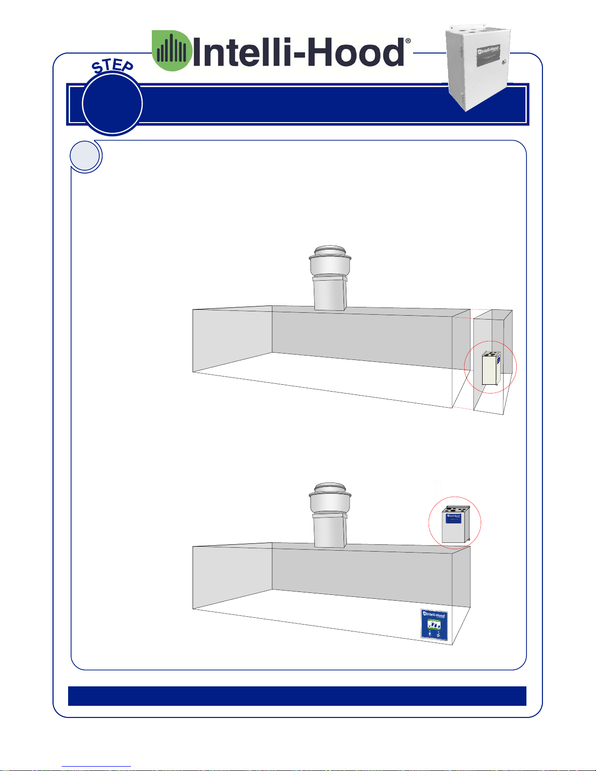
Select System Controller Location
For new construction, the hood
manufacturer typically provides a
utility cabinet in which to mount
the System Controller. If the
hood has a utility cabinet with
extra space, mount the System
Controller (and VFDs) there.
For retrofits, the System
Controller is typically mounted
above the hood. Select a location
that is easily accessible and close
to where the Touchpad will be
mounted. Ideally, you should
secure it to a wall. DO NOT
PENETRATE THE HOOD
EXHAUST PLENUM.
Melink Corporation (513) 965-7300 www.melinkcorp.com
4
1
Install System Controller
B
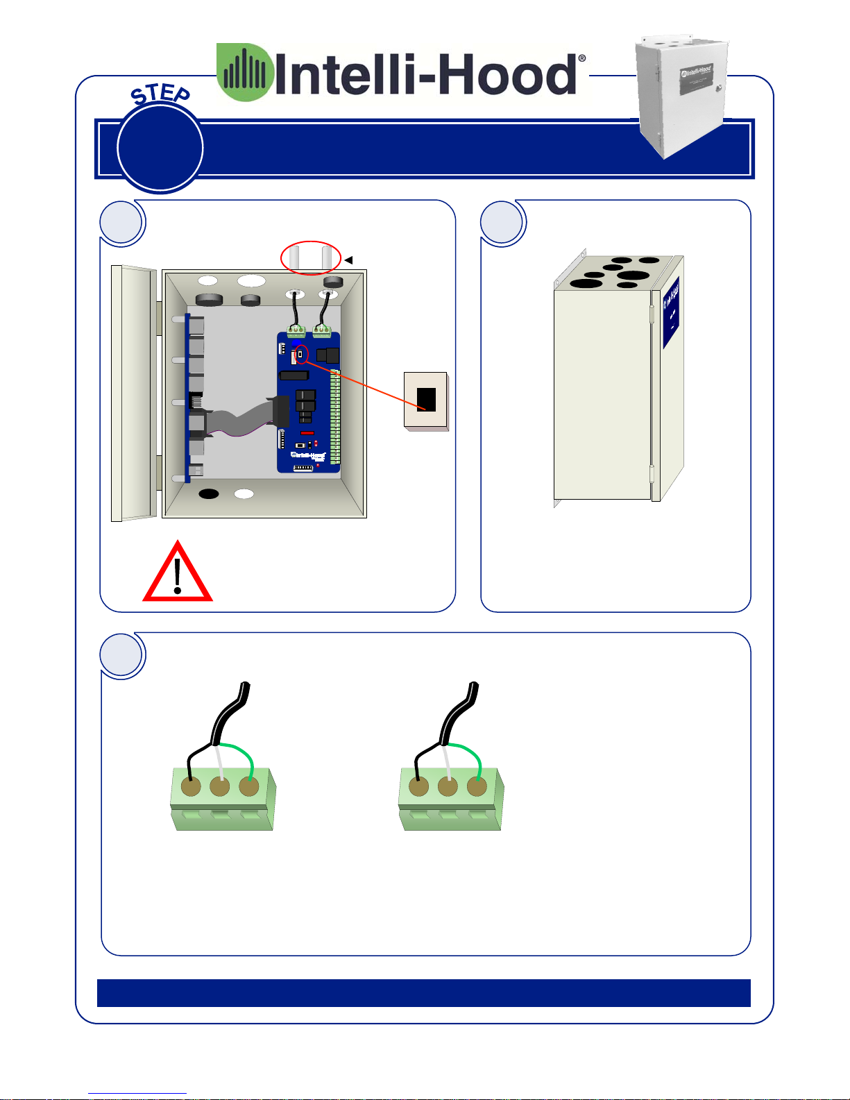
Turn Off Power Switch Wire System Controller
115V or 230V
ON
OFF
Turn OFF the System Controller power switch before
wiring. Also turn off the
breaker feeding this circuit.
C
For both New Construction & Retrofits, wire the System Controller
using the hood light circuit. The
circuit must be 115V to 230V, at
50-60Hz. Maximum input current
is 17A.
D
115/230V
INPUT
L N G
Wire gauge per NEC; allowable size range is 16AWG to 12AWG.
New Construction & Retrofits:
Main Input Power
from Hood Light Circuit
115-230 VAC @ 50/60Hz; 17A Max
Melink Corporation (513) 965-7300 www.melinkcorp.com
Wire Connections Inside System Controller
115/230V (15A)
LIGHTS (OUTPUT)
L N G
New Construction:
Outgoing Power to Hood Lights
Output Voltage Matches Input
15 Amps max
It is not required to use
these output terminals if
there are other provisions
in place to control the
hood lights. Note that
output voltage will be the
same as the input voltage.
Tungston Output Rating:
8A @ 120V
5.4A @ 240V
Retrofits:
5
2
Install Variable Frequency Drive
A
For new construction, the Intelli-Hood includes a Variable Frequency Drive or VFD for each
kitchen exhaust and make-up air fan. This type of starter is for use with 3-phase motors only. It
not only turns the fans on and off, but also varies the speed of the motors by varying the output
frequency and voltage. Therefore, you do not need a conventional magnetic motor starter with
our system. Caution: If you have a tempered make-up air unit, then the control circuit for the
heating system must be fed by a separate power source and NOT from the VFD! The output of
the VFD must be wired to the motor ONLY and NOT to a transformer or any part of a control cir-
cuit!
If there is a make-up air unit, then the VFD for this unit must be interlocked with the fire suppression micro-switch so that this fan turns off in the event of a fire. This is accomplished by connecting a low-voltage cable between designated terminals on the VFD (01 and 04 for Allen-Bradley)
and the Normally Closed (NC) terminals on the micro-switch. Caution: With variable frequency
drives, there must be a separate conduit run for the output of each VFD (inputs may be run together if desired). If this is not done, there is a strong probability of problems due to line interference and inaccurate motor control.
For retrofits, the only difference between new construction and retrofits is that on retrofits you
will already have conventional magnetic motor starters installed. In most cases, it is
recommended that you install the VFD on the output side of the existing starters. This will enable
the cooks/chefs to use the existing hood fan (and light) switch and not have to change their habits. This will also allow you to keep the existing circuit intact between the magnetic starter for the
make-up air unit and the fire suppression system micro-switch.
Verify Variable Frequency Drive Wiring
All wiring must comply with the National Electric Code (NEC
and local code requirements.
Melink Corporation (513) 965-7300 www.melinkcorp.com
6
2
Install Variable Frequency Drive
B
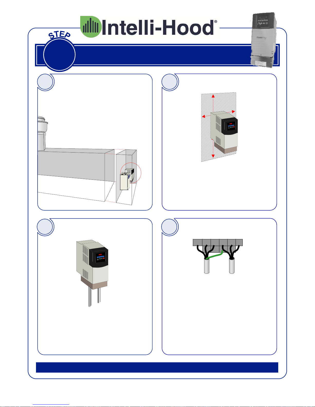
For retrofits, each VFD is typically
mounted on the output side of the existing motor starter, which is often located
in an electrical room, above the hoods,
or inside a utility cabinet. For new con-
struction, the hood manufacturer typi-
cally provides a utility cabinet in which to
mount the VFDs.
D
Select VFD Location Check VFD Location
Mount VFD Wire VFD
C
5”
1”
1”
5”
The location must be relatively free of dirt,
grease, and water. The ambient temperature must be between +14 degrees F and
+122 degrees F. There should be 5” of
clearance on the top and bottom and 1” on
the sides for adequate ventilation/cooling.
E
L1 L2 L3 U V
3-phase
input from
breaker or
magnetic
motor starter
3-Phase
Input
Mount each VFD with appropriate fasteners.
Then install separate conduit for the input
and output power wiring to prevent electrical
interference between the conductors.
Melink Corporation (513) 965-7300 www.melinkcorp.com
3-Phase
Output
Remove the VFD top cover and connect
the line voltage wiring to the VFD input
power terminal block as shown above.
Then connect the output power from the
terminal block to the respective fan motor
on the roof. The ground wire must be a
minimum of 14 AWG and as short as possible. The output wiring for each VFD
MUST be in a separate conduit run.
BR+
BR-
G
W
3-phase
output to
fan motor
7

3
Install Touchpad
A
C
Remove Existing Switches
Before removing the switch
cover plate, turn off the circuit
breaker.
For retrofits, if you want to replace the
existing fan and light switch with our
Touchpad, remove these switches from the
junction box. Then remove the existing
wires to make room for the Touchpad Cable.
Plug In Cable Mount Touchpad
B
Run the Touchpad Cable inside the existing conduit and leave approximately 5
inches of slack inside the junction box.
You will connect the other end of the Cable
to the System Controller in Step 9.
D
Run Touchpad Cable
O
Plug the connector into the receptacle on
the back of the Touchpad.
Melink Corporation (513) 965-7300 www.melinkcorp.com
Mount the Touchpad to the junction box
and secure the cover plate by snapping it
on.
8
3
Install Touchpad
A
C
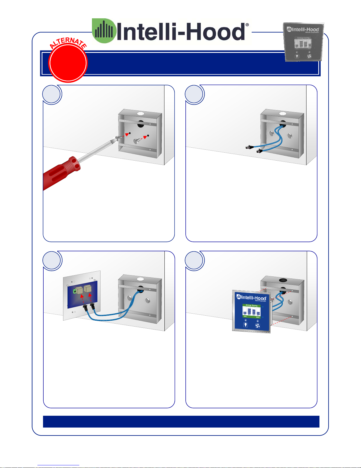
Install Surface Mount Box
Install the Surface Mount box by attaching
screws through the holes provided inside
the box. If possible to bring cable in
through the wall behind the box, first drill a
1” hole in the wall. If not, install 3/4” conduit stubbed up above the ceiling for the
cable run.
Plug In Cables Mount Touchpad
B
Run the Touchpad Cable inside the 3/4”
conduit or through the back of the box and
leave approximately 5 inches of slack inside the junction box. You will connect the
other end of the Cable to the System Controller in Step 9. If another device will be
installed downstream of the Touchpad, run
two cables.
D
Run Touchpad Cable
O
Plug the connector(s) into the receptacle
on the back of the Touchpad.
Melink Corporation (513) 965-7300 www.melinkcorp.com
9
Mount the Touchpad to the junction box
and secure the cover plate by snapping it
on.
4
Install Exhaust Temperature Sensor
4
5
A
B
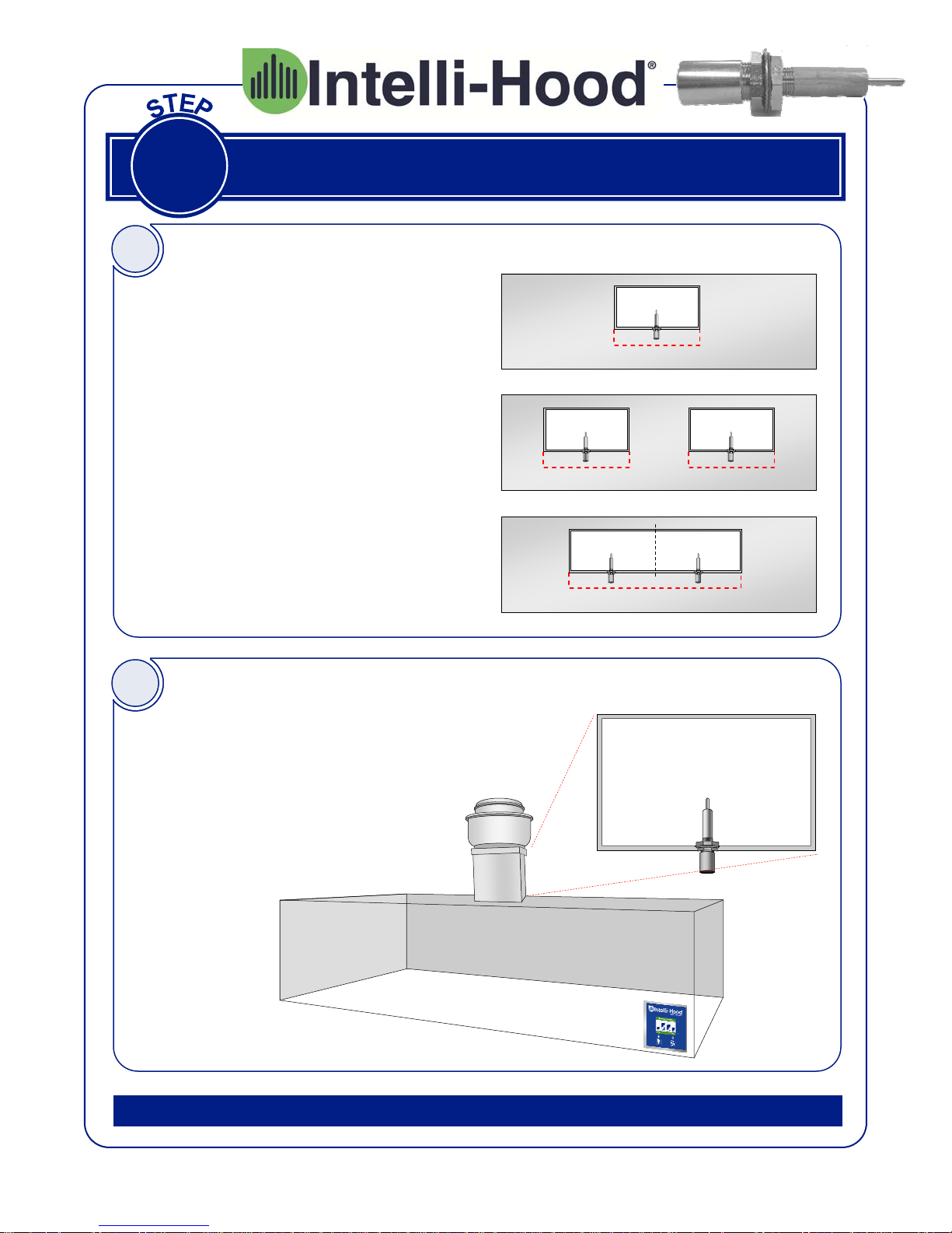
Determine Number of Sensors
Install one (1) Temperature Sensor
per exhaust duct, if the length of the
duct is less than 24”. In most cases
this will mean one Temperature
Sensor per hood.
In some cases, this will mean two
Temperature Sensors per hood.
If the length of the duct is more than
24”, then install two Temperature
Sensors in order to obtain a better
average reading.
Select Location for Mounting Sensor
L < 24” (600mm)
Hood 1 (Top View)
L ≤ 24” (600mm)
Hood 2 (Top View)
L ≥ 24” (600mm)
Hood 3 (Top View)
L ≤ 24” (600mm)
Select a location for mounting each
Temperature Sensor. The tip of the
sensor should be inside the center
of the duct to sense the average
temperature. For most installations,
proceed with steps C-F on page
10. An alternate mounting procedure is described in steps C-J on
pages 11 and 12.
Melink Corporation (513) 965-7300 www.melinkcorp.com
10
Duct Top View
 Loading...