

Page 1
Design & Engineering Services
Demand Control Ventilation for Commercial
Kitchen Hoods
ET 07.10 Report
Prepared by:
Design & Engineering Services
Customer Service Business Unit
Southern California Edison
June 30, 2009
Page 2

Demand Control Ventilation for Commercial Kitchen Hoods ET 07.10
Acknowledgements
Southern California Edison’s Design & Engineering Services (D&ES) group is responsible for
this project. It was developed as part of Southern California Edison’s Emerging Technology
program under internal project number ET 07.10. D&ES project manager Angelo Rivera
conducted this technology evaluation with overall guidance and management from Paul
Delaney. For more information on this project, contact Angelo.Rivera@sce.com.
Disclaimer
This report was prepared by Southern California Edison (SCE) and funded by California
utility customers under the auspices of the California Public Utilities Commission.
Reproduction or distribution of the whole or any part of the contents of this document
without the express written permission of SCE is prohibited. This work was performed with
reasonable care and in accordance with professional standards. However, neither SCE nor
any entity performing the work pursuant to SCE’s authority make any warranty or
representation, expressed or implied, with regard to this report, the merchantability or
fitness for a particular purpose of the results of the work, or any analyses, or conclusions
contained in this report. The results reflected in the work are generally representative of
operating conditions; however, the results in any other situation may vary depending upon
particular operating conditions.
Southern California Edison
Design & Engineering Services June 2009
Page 3

Demand Control Ventilation for Commercial Kitchen Hoods ET 07.10
ABBREVIATIONS AND ACRONYMS
MUA Make-Up Air
cfm Cubic Feet Per Minute
DCV Demand Control Ventilation
HVAC Heating Ventilation and Air Conditioning
IR Infrared
MDL Micro Data Loggers
CT Current Transducers
FLA Full Load Amps
hp Horse Power
SF Supply Fan
Southern California Edison Page i
Design & Engineering Services June 2009
Page 4

Demand Control Ventilation for Commercial Kitchen Hoods ET 07.10
FIGURES
Figure 1 Commercial Kitchen Exhaust Hood Styles1..........................4
Figure 2 Commercial Kitchen MUA Configuration types2...................5
Figure 3 Melink Intelli-HOOD HARDWARE (Court esy of Melink®).........7
Figure 4 Melink Intelli-Hood Heat and Smoke Detection (Courtesy
of Melink
Figure 5 Monitoring Equipment Installation ...................................10
Figure 6 Typical Demand Usage for EF 160 at Desert Springs
Marriott ...................................................................18
Figure 7 Typical Demand Usage for EF 8 at The Westin Mission Hills .20
Figure 8 Typical Demand Usage for EF 1,2,3 at El Pollo Loco............22
Figure 9 Typical Demand Usage for EF 1 at Panda Express..............24
Figure 10 Typical Demand Usage fro EF 1 at Farmer Boys...............26
Figure 11 Desert Springs Marriott Hood 1 System A.......................28
Figure 12 Desert Springs Marriott Hood 2 System A.......................29
Figure 13 Desert Springs Marriott Hood 3 System A.......................29
Figure 14 Desert Springs Marriott Hood 1 System B.......................30
Figure 15 Desert Springs Marriott Hood 2 System B.......................30
Figure 16 Desert Springs Marriott Hood 3 System B.......................31
Figure 17 Typical Demand Usage for EF 159 at Desert Springs
Marriott ...................................................................31
®
).................................................................8
Figure 18 Typical Demand Usage for EF 161 at Desert Springs
Marriott ...................................................................32
Figure 19 Typical Demand Usage for EF 162 at Desert Springs
Marriott ...................................................................32
Figure 20 Typical Demand Usage for EF 163 at Desert Springs
Marriot.....................................................................33
Figure 21 Typical Demand Usage for EF 164 at Desert Springs
Marriott ...................................................................33
Figure 22 Westin Mission Hills Hood 1 ..........................................34
Figure 23 Westin Mission Hills Hood 2 ..........................................35
Figure 24 Westin Mission Hills Hood 3 ..........................................36
Figure 25 Typical Demand Usage for EF 7 at Westin Mission Hills .....36
Figure 26 Typical Demand Usage for EF 9 at Westin Mission Hills .....37
Figure 27 Typical Demand Usage for EF 10 / MUA at Westin Mission
Hills.........................................................................37
Figure 28 Typical Demand Usage for SF 2 at Westin Mission Hills .....38
Southern California Edison Page ii
Design & Engineering Services June 2009
Page 5

Demand Control Ventilation for Commercial Kitchen Hoods ET 07.10
Figure 29 Typical Demand Usage for SF 3 at Westin Mission Hills .....38
Figure 30 El Pollo Loco Hood 1 ....................................................39
Figure 31 El Pollo Loco Hood 2 ....................................................40
Figure 32 Typical Demand Usage for MUA at El Pollo Loco...............40
Figure 33 Panda Express Hood 1 .................................................41
Figure 34 Panda Express Hood 2 .................................................42
Figure 35 Typical Demand Usage for EF 2 / MUA at Panda Express...42
Figure 36 Farmer Boys Hood 1....................................................43
Figure 37 Farmer Boys Hood 2....................................................44
Figure 38 Farmer Boys Hood 3....................................................45
Figure 39 Typical Demand Usage for EF 1 at Farmer boys...............45
Figure 40 Typical Demand Usage for EF 2 at Farmer Boys...............46
TABLES
Table 1 Overall Field Evaluation Results..........................................2
Table 2 Overall Field Evaluation Results For All Sites ......................15
Table 3 Desert Springs Marriott Exhaust Fan Results ......................16
Table 4 Desert Springs Marriott MUA Results.................................17
Table 5 Westin Mission Hills Results.............................................19
Table 6 El Pollo Loco Results.......................................................21
Table 7 Panda Express Results....................................................23
Table 8 Farmer Boys Results.......................................................25
EQUATIONS
Equation 1 Percentage Average kW Reduction...............................14
Equation 2 Average Daily Operational Hours .................................14
Southern California Edison Page iii
Design & Engineering Services June 2009
Page 6

Demand Control Ventilation for Commercial Kitchen Hoods ET 07.10
CONTENTS
EXECUTIVE SUMMARY _______________________________________________ 1
INTRODUCTION ____________________________________________________ 3
Objective .............................................................................. 3
CONFIGURATIONS _________________________________________________ 4
Baseline................................................................................5
Demand Control Ventilation System..........................................6
Hardware.........................................................................6
Controls...........................................................................7
APPROACH_______________________________________________________ 9
Monitoring Equipment.............................................................9
TEST SITE DESCRIPTIONS_____________________________________________ 11
Desert Springs Marriott.........................................................11
Westin Mission Hills..............................................................12
El Pollo Loco........................................................................12
Panda Express.....................................................................12
Farmer Boys........................................................................13
RESULTS AND DISCUSSION___________________________________________ 14
Desert Springs Marriott.........................................................15
Westin Mission Hills..............................................................18
El Pollo Loco........................................................................20
Panda Express.....................................................................23
Farmer Boys........................................................................25
CONCLUSIONS ___________________________________________________ 27
Recommendations................................................................27
APPENDIX A – DESERT SPRINGS MARRIOTT ______________________________ 28
Kitchen Hood Description..................................................28
PPENDIX B – WESTIN MISSION HILLS__________________________________ 34
A
Kitchen Hood Description..................................................34
A
PPENDIX C – EL POLLO LOCO ______________________________________ 39
Southern California Edison Page iv
Design & Engineering Services June 2009
Page 7

Demand Control Ventilation for Commercial Kitchen Hoods ET 07.10
Kitchen Hood Description..................................................39
A
PPENDIX D – PANDA EXPRESS ______________________________________ 41
Kitchen Hood Description..................................................41
APPENDIX E – FARMER BOYS ________________________________________ 43
Kitchen Hood Description..................................................43
REFERENCES _____________________________________________________ 47
Southern California Edison Page v
Design & Engineering Services June 2009
Page 8

Demand Control Ventilation for Commercial Kitchen Hoods ET 07.10
EXECUTIVE SUMMARY
Commercial kitchen hoods (hoods) are a significant componen t of energy consumption in
restaurant and fast-food kitchens. They function to reduce fire hazards and exhaust cooking
effluent to comply with air quality standards within a commercial kitchen. Exhaust hoods in
these kitchens are normally tied to a make-up air (MUA) unit that balances building
pressure during the kitchens operation. Generally, the hoods’ exhaust requirements are
sized to peak cooking usage of each appliance under the hood. Typical hoods have a simple
“on” or “off” control strategy. When the hood is on, its exhaust and make up air fans are on
at full speed or not at all. In reality food is not being cooked at all times t herefore not
needing the peak exhaust requirements. Due to the common control strategies employed in
most commercial kitchens a significant amount of energy is wast ed on venting unnecessary
cubic feet per minute of air when appliances are not fully used. It is evident that there is an
opportunity for energy efficient savings. The Melink Int elli-Hood demand control ventilation
system (DCV) is an energy management system for commercial kitchen hoods. It optimizes
energy efficiency by reducing the exhaust and make up air fan speed. This is accomplished
by leveraging an infrared and temperature sensors to determine the minimum amount of
exhaust air required to capture and contain effluent from the cookline.
The primary objective of this project is to verify field performance and demonstrate how the
Melink Intelli-Hood demand control ventilation (DCV) system can reduce energy costs. The
projects secondary objective is to evaluate the market sectors impacts on field performance
and energy reduction on a DCV system. The different market sectors can have different
hours of operation, appliances, and kitchen exhaust hood configurations. For this field
evaluation two hotels and three quick-service restaurants were chosen. Also in this field
evaluation only the exhaust and make up air fan motor energy savings were accounted for.
Air conditioning savings, due to heat load reduction in the kitchen area, were not accounted
for.
The Melink Intelli-Hood DCV system was shown to significantly reduce the energy
consumption and electrical demand associated with operating a commercial kitchen exhaust
hood.
daily energy consumption, annual energy consumption, annual savings, percentage energy
usage reduction, and estimated annual operational cost for all hood data at each site. The
savings results from the Melink Intelli-Hood DCV system installation can realize a 37-62%
energy savings over current commercial kitchen hoods. The DCV system was most effective
in the hotel market sector due to the amount of hoods, amount of HP servicing the hotel,
and the hours of operations. Hotel kitchens are sized for peak food production - defined as
the maximum food prepared at any given time in a hotel’s kitchen. The hotel’s kitchen
sizing also means there are multiple hoods and higher amounts of HP needed to meet the
maximum food demands. Since maximum food demands rarely happen, the hotel market
sector has a high potential for savings. Most of the time there is limited kitchen use
occurring in a given day, allowing a DCV system to save energy by running at minimal
exhaust settings.
Table 1 lists the average kW draw, percentage reduction, daily operational values,
Southern California Edison Page 1
Design & Engineering Services June 2009
Page 9
Demand Control Ventilation for Commercial Kitchen Hoods ET 07.10
In the quick-service restaurant market sector there was a large percentage energy drop at
each site, but a significantly lower energy savings. The lower energy savings were attributed
to the lower hp motors, operational time, appliance usage, and amount of hoods. In
addition to energy savings, with the installation of a DCV system, there was the added
benefit of noise reduction from the kitchens’ exhaust hood system.
This evaluation also showed that the performance of the DCV system was highly impacted
by the different appliance types and their controls. The appliance types ranged from lightduty to extra heavy-duty. The opportunity for energy savings decreased as the appliances
duty rating got closer to extra heavy-duty rated appliances. The higher the rating the higher
the heat load and more effluent the appliance created during cooking. The opportunity for
savings also decreased when the appliances controls created a constant heat load when
either in use or not in use. Appliances that only produce heat when cooking gave a large
opportunity for savings.
TABLE 1 OVERALL FIELD EVALUATION RESULTS
Overall Results For All Sites
Average demand without DCV
system (kW)
Average demand with DCV
system (kW)
Average kW reduction (%)
Daily Operational Hours
Daily energy usage without
DCV system (kWh/day)
Daily energy usage with DCV
system (kWh/day)
Annual energy usage without
DCV system (kWh/yr)
Annual energy usage with
DCV system (kWh/yr)
Annual energy savings with
DCV system (kWh/yr)
Percentage energy usage
reduction (kWh/yr)
Estimated annual operational
savings (@$0.15 a kWh)
Desert Springs
Marriott
Westin
Mission Hills
El Pollo
Loco
Panda
Express
Farmer
Boys
27.9 12.1 4.7 5.2 2.9
10.7 5.2 2.9 2.0 1.4
61.6% 57.0% 38.3% 61.5% 51.7%
24 24 15.36 13.1 15.83
670 291 72 67 44
257 125 45 26 23
244,500 106,034 26,313 24,620 16,159
93,681 45,595 16,442 9,559 8,276
150,819 60,439 9,871 15,061 7,884
61.7% 57.0% 37.5% 61.2% 48.8%
$22,623 $9,066 $1,481 $2,259 $1,183
Southern California Edison Page 2
Design & Engineering Services June 2009
Page 10

Demand Control Ventilation for Commercial Kitchen Hoods ET 07.10
INTRODUCTION
Commercial kitchen hoods are a significant component of energy consumption in
commercial kitchens. They function to reduce fire hazards and exhaust cooking effluent to
comply with air quality standards within a commercial kitchen. Exhaust hoods in
commercial kitchens are normally tied to a make-up air (MUA) unit that balances building
pressure during the kitchens operation. Generally, commercial kitchen hoods exhaust
requirements are sized to peak cooking usage of each appliance under the hood. Typical
commercial kitchen hoods have a simple “on” or “off” control strategy. When the hood is on,
its exhaust and MUA fans are on at full speed or not at all. In reality food is not being
cooked at all times therefore not needing the peak exhaust requirements. Due to the
common controls strategies employed in most commercial kitchens a significant amount of
energy was wasted on venting unnecessary cubic feet per minute of air (cfm) when
appliances were not fully used. It was evident that there was an opportunity for change. A
demand control ventilation system (DCV) is an energy management system for commercial
kitchen hoods. It optimizes energy efficiency by reducing the exhaust and MUA fan speed.
This is accomplished by leveraging sensors to determine the minimum amount of exhaust
air required to capture and contain effluent from the cookline.
Derived from the SCE service territory database there are 37,212 restaurants, 5,553 hotels,
3,313 grocery stores, 9,105 schools/colleges, and 1,076 hospitals. Within the SCE service
territory there is a total of 56,156 customers with the potential to use DCV systems. Within
California it is estimated there are 124,040 restaurants, 18,510 hotels, 11,043 grocery
stores, 30,553 schools and 3,243 hospitals. Within all of California it is estimated there is a
total of 187,187 customers with the potential to use DCV systems. This was estimated by
assuming SCE has 30%, PGE has 35%, SDGE has 20% and municipal utilities have 15% of
Californians total customer utility service. For some market segments the applicability of the
DCV technology might be as low as 50% and as high as 80%.
OBJECTIVE
The Primary objective of this project is to verify field performance and demonstrate
how the Melink Intelli-Hood demand control ventilation (DCV) system can reduce
energy costs. The project’s secondary objective is to evaluate the market sectors’
impact on field performance and energy reduction using a DCV system. The different
market sectors can have different hours of operation, appliances, and kitchen
exhaust hood configurations.
Southern California Edison Page 3
Design & Engineering Services June 2009
Page 11
Demand Control Ventilation for Commercial Kitchen Hoods ET 07.10
CONFIGURATIONS
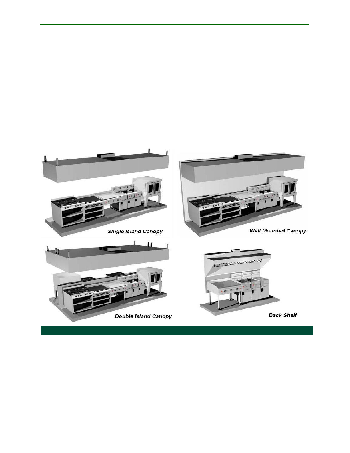
Commercial kitchen exhaust hoods can come in many different configurations. These
varying configurations can impact the hoods ability to capture and contain effluent,
including odors, gases, heat, and oil. The better the system is designed, the lower the cfm
needed to capture effluent and the lower the energy consumption of the kitchen exhaust
hood. The hood style, construction features, and proximity of hood installation, give
different capture areas, dictating the necessary exhaust cfm. The hood styles, in order from
highest exhaust requirement to least, generally include; single-island canopy hood, wallmounted canopy hood, double-island canopy hood, and back-shelf hood, as depicted in
Figure 1.
FIGURE 1 COMMERCIAL KITCHEN EXHAUST HOOD STYLES1
The appliances and the food being cooked under the hood can factor in the exhaust cfm
requirements. Cooking appliances are categorized as light, medium, heavy, or extra heavyduty, due to their strength of thermal plumes it can create. Thermal plume strength is also
affected by the type of food being cooked on the appliance. The stronger the thermal plume
the more exhaust cfm that is required.
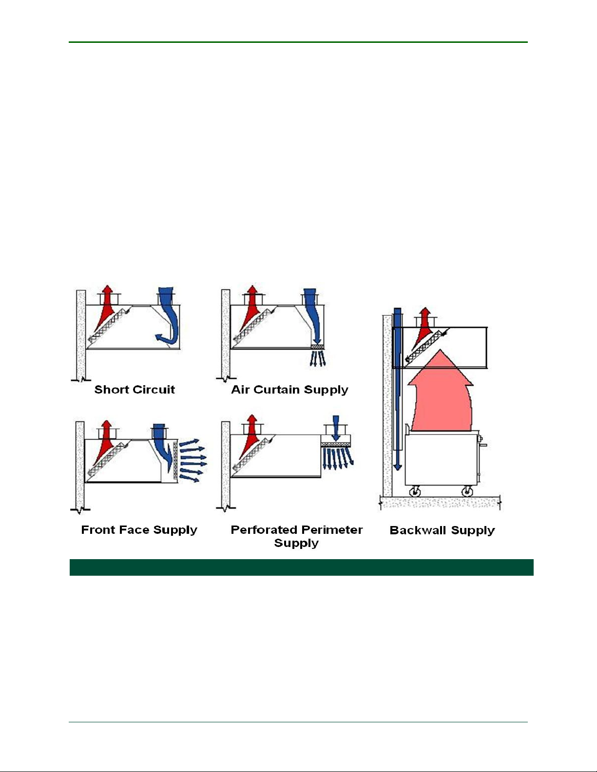
Configuration of how MUA is introduced into the kitchen is also an important configuration.
MUA balances the pressure of the kitchen when exhaust fans are in operation. As air is
exhausted out of the hood, the air is replaced by an equal volume of air. Typically, a
dedicated MUA unit is employed in a commercial kitchen. A dedicated MUA unit only makes
up a percentage of the air exhausted. By not matching cfm exhausted air, the kitchen keeps
Southern California Edison Page 4
Design & Engineering Services June 2009
Page 12
Demand Control Ventilation for Commercial Kitchen Hoods ET 07.10
a negative pressure. The remaining air volume, not replaced by the MUA unit, is taken from
transfer air such as the dining area or a kitchens’ air handlers system. A small negative
pressure is desired to keep the kitchens odors from transferring into other areas the kitchen
is connected to. If no MUA is introduced, kitchen pressure may become too negative and
affect the capture and containment of effluent. When designing a dedicated MUA system for
a commercial kitchen, how the air is introduced into the kitchen can factor into how much
exhaust air to replace, and can affect the kitchen hoods ability to capture and contain
affluent. A poorly designed MUA system with a high exhaust replacement cfm can make a
kitchen hood perform poorly. Poorly designed MUA systems can hinder effluent or push
effluent outside of the hoods containment area and into the kitchen space. MUA can be
untreated (air taken from outside), or treated air (evaporative cooled or heated air). When
MUA is introduced into the kitchen it has the abil ity to save Heating, Ventilation and Air
Conditioning (HVAC) energy. This is accomplished by reducing the amount of conditioned air
being exhausted. The most common configuration to introduce MUA into the kitchen is
through integrated hood plenums. The different integrated hood plenums types in order of
worst design to best are: short circuit, air curtain supply, front face supply, perforated
perimeter supply, back wall supply, or any combination of integrated hood plenum types as
depicted in Figure 2.
FIGURE 2 COMMERCIAL KITCHEN MUA CONFIGURATION TYPES2
BASELINE
For this field evaluation the baseline for each site was a commercial kitchen hood
with the simple “on” or “off” control strategy. When the hood is “on” both exhaust
and make-up air units are at full speed until turned off. The customers chosen for
this field evaluation were either customer’s who needed the DCV system retrofit to
participate, or customers with an existing DCV system installed. At sites where the
DCV system was a retrofit, electrical usage was logged. At sites where the DCV
system was already installed, the keypad was used to override the DCV system
Southern California Edison Page 5
Design & Engineering Services June 2009
Page 13

Demand Control Ventilation for Commercial Kitchen Hoods ET 07.10
before monitoring electrical usage. By overriding the DCV system, the simple “on” or
“off” controls of the kitchen exhaust hood was restored to measure baseline data for
the hood.
DEMAND CONTROL VENTILATION SYSTEM
The Melink Intelli-Hood DCV system was selected for this field evaluation because, at
the time, it was the only commercially available DCV system. Although other
manufacturers are in the process of developing their DCV systems, none were
available at the time of this study. The Melink Int elli-Hood DCV system is an energy
management system for commercial kitchen exhaust hoods. It can be installed in
new construction or as a retrofit. The Intelli-Hood controls optimize energy efficiency
by reducing the exhaust and MUA fan speed by leveraging sensors to determine the
amount of exhaust air required to capture and contain effluent from the cookline.
Since cooking does not occur at a constant, the kitchen exhaust and MUA fans vary
their speed using a variable speed controller to meet the necessary minimum
exhaust air requirements. This allows the exhaust system to run at the lowest
possible speed to perform the required job. In addition, the noise level in the kitchen
is reduced significantly as the system decreases the exhaust and MUA fan speed
during low exhaust demand.
HARDWARE
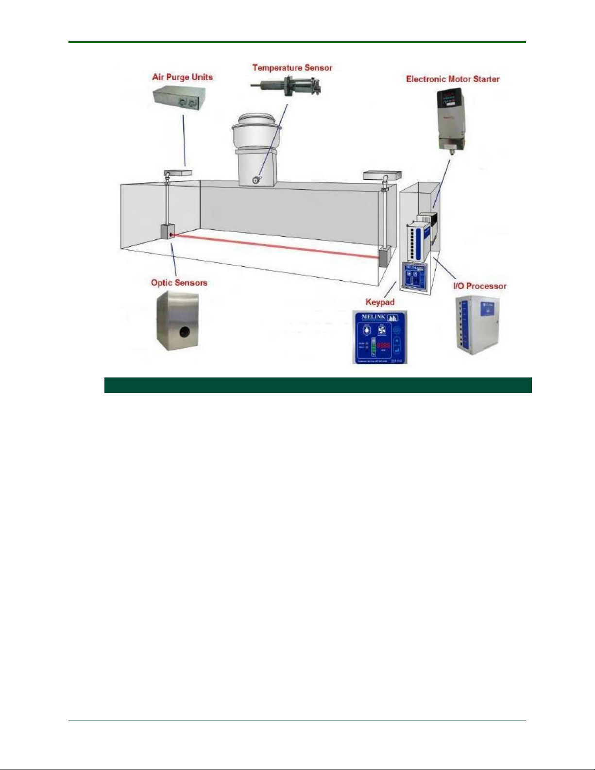
The Melink Intelli-Hood system consists of 6 pieces of hardw a re as illustrated in
Figure 3.
- I/O Processor receives inputs from the temperature sensor and optic sensor.
With the inputs received from the sensors, the processor controls the output of
the electronic motor starters. The processor also displays current operations of
each hood and is able to be programmed by the keypad.
- Temperature Sensor monitors the exhaust air temperature in the exhaust duct.
A temperature signal is transmitted to the I/O processor that uses the signal to
vary the speed in proportion to actual heat load.
- Optic Sensors monitor the presence of smoke and vapors inside the hood. With
the presence of smoke and/or vapors, a signal is sent to the I/O processor to
ramp fans to full speed to remove it.
- Air Purge Units are miniature blowers that are equipped on both the optical
transmitter and receiver to prevent grease from collecting on the optical sensor
lenses when the kitchen hood exhaust system is operating.
- Electric Motor Starter is a variable frequency drive equipped on each exhaust
and Make-up fan motor. The electric motor starter receives the signal from the
I/O processor then adjusts the motor speed to meet each hood’s needs.
- Keypad allows users to turn on the system and displays current system fan
levels. The keypad also gives the user programming capabilities for the system.
Southern California Edison Page 6
Design & Engineering Services June 2009
Page 14
Demand Control Ventilation for Commercial Kitchen Hoods ET 07.10
FIGURE 3 MELINK INTELLI-HOOD HARDWARE (COURTESY OF MELINK®)
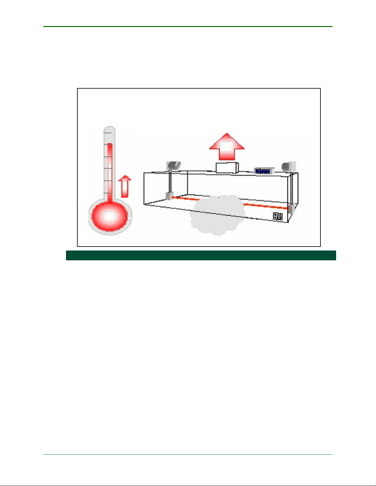
CONTROLS
The Melink Intelli-Hood system I/O processor is the brain for the whole system. The
I/O processor has the ability to control up to 4 exhaust fan motors and its
corresponding MUA units. The I/O processor displays current system fan levels for
each hood it controls on the keypad. The keypad is how different system parameters
are configured, such as electric motor starter speed rate for corresponding
temperature ranges and Infrared (IR) beam strength. The I/O processor receives
exhaust duct temperature signals for each hood from temperature sensors. The
different appliances under the hood produce heat load whether they are in use or on
stand-by. The electric motor starter varies the exhaust fan and MUA motor
depending on the temperature signal received and where it falls in the programmed
temperature parameters as illustrated in Figure 4
receiver and transmitter. The optical sensor is mounted in the bottom center on each
side of the hood. The transmitter transmits a red IR beam across the hood and when
the receiver receives intensities of less than 95% of fu ll input, a signal is sent to the
I/O processor. Usually smoke or vapors from the cookline are the cause of the
obstructions. When the signal is received the I/O processor runs the exhaust and
MUA fans at full speed, regardless of the exhaust ducts temperature, to remove
obstructions to the optical sensor as illustrated in .
. The optical sensor consists of a
Figure 4
Southern California Edison Page 7
Design & Engineering Services June 2009
Page 15
Demand Control Ventilation for Commercial Kitchen Hoods ET 07.10
The Melink Intelli-Hood different paramete rs are tailored and programmed dependent
on the configuration of the kitchen. Configurations such as hood length, hood type,
hood design, how MUA is introduced, appliance exhaust requirements, and type of
food being cooked play an important role on the different parameters. The
parameters are programmed with kitchen configurations in mind during system
commissioning to achieve optimized performance and energy savings.
Heat and Smoke
FIGURE 4 MELINK INTELLI-HOOD HEAT AND SMOKE DETECTION (COURTESY OF MELINK®)
Southern California Edison Page 8
Design & Engineering Services June 2009
Page 16

Demand Control Ventilation for Commercial Kitchen Hoods ET 07.10
APPROACH
To evaluate the field performance and demonstrate how the Melink Intelli-Hood DCV system
can reduce energy costs, each customer’s kitchen exhaust and MUA fan motor electrical
usage was monitored. In this evaluation only the exhaust and MUA fan motor energy
savings were measured. Since HVAC savings are weather dependent, cooling load reduction
savings were not accounted for due to the complexity it would bring to this field evaluation.
To determine potential energy savings realized by the Melink Intelli-Hood system at each
site, three phases were completed.
- Phase 1 - Baseline evaluation: After the customer sites were chosen to
participate in the field evaluation, the kitchen configuration was noted. The
different exhaust and MUA fan motors were found and corresponding electrical
service breakers were found. Fan motors name plate data was also recorded. A
Micro Data logger was installed on each exhaust and MUA electrical breaker to
monitor electrical usage of the corresponding fan motor. At sites where the DCV
system was a retrofit, electrical usage was logged. At sites where the DCV
system was already installed, the keypad was used to override the DCV system
before monitoring electrical usage. By overriding the DCV system, the simple
“on” or “off” controls of the kitchen exhaust hood were restored to measure
baseline data for the hood. Since the motors ran constantly at full speed under
the baseline controls of the kitchen hoods, the power draw from each fan motor
was pretty much constant. Baseline data was recorded for about one week at
each site and analyzed.
- Phase 2 - System retrofit or adjustment: After each kitchen exhaust hood
electrical usage was baselined, phase two was initiated. At sites where the simple
“on” or “off” controls strategy was employed, the DCV system hardware was
installed and system parameters were programmed during commissioning. At
sites where the DCV system was already installed, the keypad was used again to
restore the DCV system controls.
- Phase 3 - New system evaluation: After installation or adjustment of the DCV
system, the system was allowed to run for two weeks to ensure proper
performance. The DCV system’s electrical usage was monitored for about six
weeks in the quick-service restaurants and twelve weeks in the hotels.
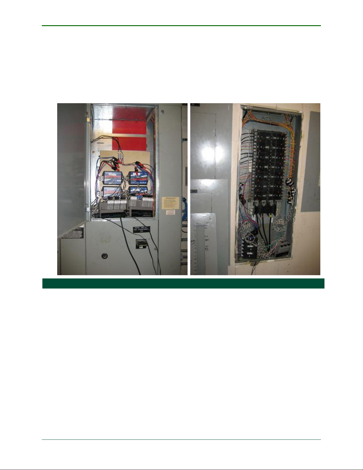
MONITORING EQUIPMENT
Micro Data Loggers, (MDL) Current Transducers, (CT) and wattnodes were also
installed in the electrical breaker servicing each exhaust and MUA fan motor at all
five sites as shown in Figure 5. The MDL logs power data coming from a wattnode.
The wattnode generates pulses from voltage readings tapped into the circuit and
amperage readings from CTs (generically, Power=voltage x amperage). Electrical
service for each fan motor was either three phase 480v delta or three- phase 208v
wye. When monitoring three phase 480v delta circuits, a WNA-3D-480P wattnode
was used. When monitoring three phase 208v wye-wired circuits, a WNA-3Y-208P
wattnode was used. The wattnode has an accuracy of
scale through 25th harmonic.
Maximum amperage draw of each fan motor dictated the CT size used for monitoring
CTs used for each of the sites were either 5 or 20 amps.
0.45% of reading + 0.05% of full
Southern California Edison Page 9
Design & Engineering Services June 2009
Page 17
Demand Control Ventilation for Commercial Kitchen Hoods ET 07.10
each motors electrical full load amps (FLA). The CTs has an accuracy of ±1% at 10%
to 130% of rated current
Power data was measured in 15-second intervals and averaged into 5-minute data
points logged by the MDL. A low sample interval was chosen to provide high
accuracy and resolution for the readings. The compiled 5-minute data was
downloaded monthly. A Fluke 43B power quality analyzer was used to verify data
collected. Spot checks were also administered each time data was downloaded and
the logger was reset.
FIGURE 5 MONITORING EQUIPMENT INSTALLATION
Southern California Edison Page 10
Design & Engineering Services June 2009
Page 18

Demand Control Ventilation for Commercial Kitchen Hoods ET 07.10
TEST SITE DESCRIPTIONS
The test sites chosen for this field evaluation include two hotel/resorts and three quick- service
restaurants. These market segments were chosen specifically because there was a lack of
energy savings information. The two hotels were also chosen due to their high potential for
energy savings because of the number of commercial kitchen hoods and their corresponding
horse power. The hotels have a large amount and variety of cooking appliances, kitch en
operation hours, number of stories and diverse kitchen use. For these reasons both the Desert
Springs Marriott and the Westin Mission Hills hotels were selected for this study. The quickservice market sector was another area of focus due to the large amount of customer foot
traffic in addition to the lack of savings information on the market sector. The three quickservice restaurants selected all had different types of menus and corresponding appliances. The
selected restaurants include an El Pollo Loco, Panda Express, and a Farmer Boys restaurant.
DESERT SPRINGS MARRIOTT
The Desert Springs Marriott hotel is located in Palm Desert, CA and serves 844 guest
rooms. The hotel stands nine stories high with the kitchen located on the ground
floor. The kitchen operates 24-hours a day, 365 days a year and serves breakfast,
lunch, dinner, room service, and all of the hotels different catering needs. The
kitchen consists of 6 wall-mounted canopy kitchen exhaust hoods. MUA is introduced
into the kitchen by integrated short circuit supply registers within each hood. There
is 21 hp of combined exhaust motor horse power to exhaust a total of 23,914 cfm.
There is 11.5 hp combined MUA motor horse power to make-up 13,804 cfm. The
MUA units replace 57% of exhaust flow from the kitchen. The air handler places
17,923 cfm of conditioned air into the kitchen space, of which 6,100 cfm of the air
comes from outside. All exhaust and MUA fan motors run on 480v service. The
Desert Springs Marriott was one of the customers where energy usage was baselined
before the DCV system was retrofitted to their kitchen exhaust hoods. When the DCV
retrofit system was installed, two systems were installed - System A and System B.
The total cost of the retrofit for the new system including labor was about $28,000.
Southern California Edison Page 11
Design & Engineering Services June 2009
Page 19

Demand Control Ventilation for Commercial Kitchen Hoods ET 07.10
WESTIN MISSION HILLS
The Westin Mission Hills hotel is located in Rancho Mirage, CA and serves 472 guest
rooms. It has a single-story kitchen that operates 18-hours a day, 365 days per
year. Even though the kitchen only operates 18-hours a day, the kitchen hoods
operate 24-hours a day providing high potential for demand controlled ventilation.
The kitchen serves breakfast, lunch, dinner, room service, and all of the hotels
catering needs. It consists of 3 wall-mounted canopy kitchen exhaust hoods. MUA is
untreated and introduced into the kitchen by an integrated air curtain supply
register, or by ceiling diffusers. There is 14 hp of combined exhaust motor horse
power to exhaust a total of 21,594 cfm. There is 8 hp combined MUA motor horse
power to make-up 14,920 cfm. The MUA units replace 69% of exhaust flow from the
kitchen. The air handler places 12,000 cfm of conditioned air into the kitchen space.
All exhaust and MUA fan motors run on 480v service. The Westin Mission Hills was
one of the customers where energy usage was baselined before the DCV system was
retrofitted into their kitchen exhaust hoods. The total cost of the retrofit for the new
system including labor was about $22,000.
EL POLLO LOCO
El Pollo Loco is a quick-service chicken restaurant located in E l M onte, CA. Store
hours are Monday - Sunday 9:00a.m. to 12:00a.m., and is open 364 days out of the
year. The kitchen is a single-story that serv es flame-grilled chicken and other menu
items. The kitchen consists of a wall-mounted canopy kitchen exhaust hood and a
single-island canopy hood. MUA is evaporative cooled air and introduced into the
kitchen by an integrated perforated perimeter supply register. There is 3 hp of
combined exhaust motor horse power to exhaust a total of 7,760 cfm. There is 3 hp
combined MUA motor horse power to make-up 5,330 cfm. The MUA units replace
69% of exhaust flow from the kitchen. The HVAC system places 5,000 cfm of
conditioned air into the kitchen space. All exhaust and MUA fan motors run on 208v
service. El Pollo Loco is one of the customers where energy usage was baselined
before the DCV system was retrofitted into their kitchen exhaust hoods. The total
cost of the retrofit for the new system including labor was about $15,500.
PANDA EXPRESS
Panda Express is a quick-service Chinese food restaurant located in Quartz Hill, CA .
Store hours are Monday - Thursday 10:30a.m. to 9:30p.m, Friday - Saturday
10:30a.m. to 10:00p.m, and Sunday 11:00a.m. to 9:00p.m. The store is open 365
days out of the year. The kitchen is a single-story that serves a variety of Chinese
food. The kitchen consists of two wall-mounted canopy kitchen exhaust hoods. MUA
is evaporative cooled air and introduced into the kitchen by an integrated perforated
perimeter supply register. There is 4 hp of combined exhaust motor horse power to
exhaust a total of 6,000 cfm. There is 1 hp combined MUA motor horse power to
make-up 4,800 cfm. The MUA units replace 80% of exhaust flow from the kitchen.
The HVAC system places 5,000 cfm of conditioned air into the kitchen space. All
exhaust and MUA fan motors run on 208v service. The Panda Express had the DCV
system previously installed before this field evalua tion. The total new construction
cost for the new system including labor was about $8,000.
Southern California Edison Page 12
Design & Engineering Services June 2009
Page 20

Demand Control Ventilation for Commercial Kitchen Hoods ET 07.10
FARMER BOYS
Farmer Boys is a quick-service American restaurant located in Irwindale, CA. Store
hours are Monday - Saturday 6:00a.m. to 10:00p.m, and Sunday 6:00a.m. to
9:00p.m and is open 364 days out of the year. The kitchen is a single-story that
serves breakfast, lunch, and dinner entrees that can be ordered at anytime of the
day. The kitchen consists of two wall-mounted canopy kitchen exhaust hoods and a
single-island canopy hood. There is no dedicated MUA unit for the kitchen. Instead
the HVAC system is introduced into the kitchen by an integrated perforated
perimeter supply register. Since there was not a dedicated MUA unit, the air supply
coming from the integrated perforated perimeter supply registers was not modulated
when the DCV system was installed. There is 2.25 hp of combined exhaust motor
horse power to exhaust a total of 6,500 cfm. The HVAC system places 2,606 cfm of
conditioned air into the kitchen space. The rest of the MUA requirements are taken
from the transfer air of the nearby dining area. All exhaust fan motors run on 208v
service. Farmer Boys had the DCV system previously installed before this field
evaluation. The total new construction cost for the new system including labor was
about $9,000.
Southern California Edison Page 13
Design & Engineering Services June 2009
Page 21

Demand Control Ventilation for Commercial Kitchen Hoods ET 07.10
RESULTS AND DISCUSSION
After the data was recorded and analyzed, power and energy consumptions were compared
between the kitchen ventilation system “with” and “without” a DCV system. Table 2 lists the
average kW draw, percentage reduction, daily operational values, daily energy
consumption, annual energy consumption, annual savings, percentage energy usage
reduction, and estimated annual operational cost for all hood data at each site. Measured
average kW for the baseline was pretty much a consistent number that fluctuated a little
from the baseline. The measured average kW for new system case was only the average of
the kW when the kitchen hood was on. The average kW for the two cases was used to
calculate the average kW reduction using Equation 1.
EQUATION 1 PERCENTAGE AVERAGE KW REDUCTION
Daily operations were 24-hours for the two hotels since they never turned off their hoods.
For the three quick-service restaurants, the hours of operation for the kitchen exhaust hood
system were estimated. These estimates were determined by using Equation 2. From the
end use monitoring equipment data was downloaded. The data was a reading of demand
draw averaged into a five-minute data point. Demand draw only occurred when the kitchen
exhaust hood system was in operation. Since any demand draw meant the kitchens’
exhaust hood system was in operation, the amount of data points with demand draw that
were counted were the demand occurrences. When all the demand occurrences were
summed they were multiplied by five minutes to give a sum of minutes of operation. The
sum of minutes was then divided by the number of days the data came from to give the
average daily operational hours.
EQUATION 2 AVERAGE DAILY OPERATIONAL HOURS
The daily energy use was then calculated by multiplying t he average kW times the
operational hours to get daily energy consumption. The daily energy consumption was then
multiplied by the number of days the restaurant was open for business to find annual
energy consumption. The difference between the baseline and the new system provided the
savings. The savings were divided by the baseline to get annual energy usage reduction.
The savings were also multiplied by the rate of fifteen cents a kilowatt hour (kWh) to
estimate the technologies’ annual operational savings. This rate was derived from SCE’s
current rate structure, averaged for applicable commercial customers.
Southern California Edison Page 14
Design & Engineering Services June 2009
Page 22

Demand Control Ventilation for Commercial Kitchen Hoods ET 07.10
The percent reduction for all the sites ranged from 37% to 62% savings. This percentage
was good, but did not translate into large energy savings or dollar savings unless the hours
of operation and horse power were high. The range of savings was also greatly impacted by
the appliances used and the corresponding food being cooked. If the appliance was rated a
medium to heavy duty and had a constant heat load, the savings opportunity decreased
significantly. For example, charbroilers have a constant heat load whether food is in the
process of cooking or not. Appliances rated light to medium usually created heat load when
cooking occurred, resulting in large savings opportunities.
TABLE 2 OVERALL FIELD EVALUATION RESULTS FOR ALL SITES
Overall Results For All Sites
Average demand without DCV
system (kW)
Average demand with DCV
system (kW)
Average kW reduction (%)
Daily Operational Hours
Daily energy usage without
DCV system (kWh/day)
Daily energy usage with DCV
system (kWh/day)
Annual energy usage without
DCV system (kWh/yr)
Annual energy usage with
DCV system (kWh/yr)
Annual energy savings with
DCV system (kWh/yr)
Percentage energy usage
reduction (kWh/yr)
Estimated annual operational
savings (@$0.15 a kWh)
Desert Springs
Marriott
Westin
Mission Hills
El Pollo
Loco
Panda
Express
Farmer
Boys
27.9 12.1 4.7 5.2 2.9
10.7 5.2 2.9 2.0 1.4
61.6% 57.0% 38.3% 61.5% 51.7%
24 24 15.36 13.1 15.83
670 291 72 67 44
257 125 45 26 23
244,500 106,034 26,313 24,620 16,159
93,681 45,595 16,442 9,559 8,276
150,819 60,439 9,871 15,061 7,884
61.7% 57.0% 37.5% 61.2% 48.8%
$22,623 $9,066 $1,481 $2,259 $1,183
DESERT SPRINGS MARRIOTT
The Desert Springs Marriott shows that hotels are a good application for a DCV
system. Table 3 shows the results for all exhaust fans at the Desert Springs Marriott.
The number of hoods, appliances usage, type of appliances, hours of operation, and
horse power affected the DCV systems performance and its corresponding savings
greatly. The number of kitchen hoods and their horse power attributed to the
exhaust fan motor energy consumption of 115,078 kWh a year. After the DCV
system was installed the energy consumption dropped by 69% to 50,757 kWh a
year. The savings are 115,078 kWh a year. The reduction of 69% can be attributed
to the appliances usage. Out of 6 hoods only one cookline was actually on 24 hours
in a day, which was the room service cookline EF 164. The other five cooklines had
appliances either turned off, or were put on a very low setting from10:00 p.m. to
4:00 a.m. the next day. Almost all EFs dropped to a very low state between those
times. EF 159, 161, 162, and 163 all modulated very little throughout the day as
shown in Appendix A, Figure 17 to Figure 20. Those EFs are all batch cooking
Southern California Edison Page 15
Design & Engineering Services June 2009
Page 23

Demand Control Ventilation for Commercial Kitchen Hoods ET 07.10
cooklines with appliances that were either on or off. When the appliances were off
there was no heat load to exhaust. When the appliances were on the savings were
reduced and were dependent on the appliances duty rating. The appliances range
from light duty to medium duty. The duty of the appliance combined with the limited
activity provided for large savings seen at the site.
TABLE 3 DESERT SPRINGS MARRIOTT EXHAUST FAN RESULTS
Desert Springs Marriott
Exhaust fan motors
Average demand without DCV
system (kW)
Average demand with DCV
system (kW)
Average kW reduction (%)
Daily Operational Hours
Daily energy usage without
DCV system (kWh/day)
Daily energy usage with DCV
system (kWh/day)
Annual energy usage without
DCV system (kWh/yr)
Annual energy usage with
DCV system (kWh/yr)
Annual energy savings with
DCV system (kWh/yr)
Percentage energy usage
reduction (kWh/yr)
EF 159 EF 160 EF 161 EF 162 EF 163 EF 164
Combined
Data
1.5 6.4 1.9 1.7 2.0 5.5 18.9
0.1 3.8 0.4 0.4 0.3 0.9 5.8
93.5% 41.1% 78.5% 75.9% 86.8% 84.3% 69.4%
24 24 24 24 24 24 24
36 153 45 41 47 133 454
2 90 10 10 6 21 139
13,146 55,966 16,282 14,842 17,165 48,435 165,836
855 32,961 3,501 3,570 2,266 7,604 50,757
12,290 23,005 12,780 11,272 14,899 40,832 115,078
93.5% 41.1% 78.5% 75.9% 86.8% 84.3% 69.4%
Estimated annual operational
savings (@$0.15 a kWh)
Table 4 shows the results from the six MUA units. MUA is introduced to the kitchen
through an integrated short circuit register inside the hood, which can create spillage
of effluent from the kitchen exhaust hood. As a general rule of thumb, only 15%
exhaust cfm should be made up by a short circuit style hoods. Any amount above
15% of the exhaust cfm starts to degrade the hoods ability to capture and contain
effluent. The Desert Springs Marriott was exhausting 57%. Since the percentage was
so high, the MUA units were turned off during the initia l commissioning of the
system. The customer noticed the building pressure was too negative and decided to
turn two of the MUA units back on. The energy savings from turning off four of the
MUA units was 45% or 35,741 kWh. For this study MUA energy savings were
accounted for as part of the savings because the customers can see the impact on
their energy usage and their corresponding bill. The total savings of the new system
was 62% or 150,819 kWh. However, the EF energy savings, as the MUA savings
could have been accomplished without a DCV system.
$1,844 $3,451 $1,917 $1,691 $2,235 $6,125 $17,262
Southern California Edison Page 16
Design & Engineering Services June 2009
Page 24

Demand Control Ventilation for Commercial Kitchen Hoods ET 07.10
TABLE 4 DESERT SPRINGS MARRIOTT MUA RESULTS
Desert Springs Marriott
MUA
Average demand without
DCV system (kW)
Average demand with
DCV system (kW)
Average kW reduction
(%)
Daily Operational Hours
Daily energy usage
without DCV system
(kWh/day)
Daily energy usage with
DCV system (kWh/day)
Annual energy usage
without DCV system
(kWh/yr)
Annual energy usage
with DCV system
(kWh/yr)
Annual energy savings
with DCV system
(kWh/yr)
Percent energy usage
reduction (kWh/yr)
Estimated annual
operational savings
(@$0.15 a kWh)
MUA 10 MUA 11 MUA 6 MUA 7 MUA 8 MUA 9
Combined
Data
1.0 1.0 0.8 2.1 2.8 1.3 9.0
0.0 0.0 0.0 2.1 2.8 0.0 4.9
100.0% 100.0% 100.0% 0.0% 0.0% 100.0% 45.4%
24 24 24 24 24 24 24
25 24 19 51 67 31 216
0 0 0 51 67 0 118
9,023 8,585 6,920 18,571 24,353 11,213 78,665
0 0 0 18,571 24,353 0 42,924
9,023 8,585 6,920 0 0 11,213 35,741
100.0% 100.0% 100.0% 0.0% 0.0% 100.0% 45.4%
$1,353 $1,288 $1,038 $0 $0 $1,682 $5,361
Figure 6 provides an example of a typical demand profile for exhaust fan EF 160. EF
160 is the kitchens main line, and handles a large amount of short order cooking.
The black solid line represents the baseline case that consistently draws around 6.5
kW. This consistent demand draw is due to the fans simple “on” or “off” control
strategy. The minor variation of the baseline is due to the loading and unloading of
the exhaust fan as effluent is exhausted. The dashed redline represents the new
system case (with DCV installed). As expected, the fan motor demand drops
significantly from 10:00p.m. to 4:00 a.m. Between these hours, the short order food
demands for the hotel are very low, so the kitchen staff turns off or runs the
appliances at the lowest set point under the hood. With the appliances off or at low
settings, there is little, if any, heat produced that needs exhausting. The DCV system
was programmed to decrease fan speed as low as possible when the exhaust
temperature dropped significantly. The dropped fan speed during this period of time
translated into large demand reductions. Between 4:00a.m. to 7:00a.m. a rise in
energy demand occurs as some appliances are turned on and at around 7:30 a.m. all
appliances are fully functional and the energy demand fluctuates depending on the
cooking taking place. This routine occurs about the same time everyday. However, to
account for the variations in appliance shut offs; cooking demand during operational
hours, and special-events catering, an average was taken from the 12 weeks of data.
The average demand draw for EF 160 with the DCV system was 3.8 kW, which is
Southern California Edison Page 17
Design & Engineering Services June 2009
Page 25

Demand Control Ventilation for Commercial Kitchen Hoods ET 07.10
represented by the dashed green line which gives a visual representation of energy
usage drop from baseline to the new system case. Typical demand profile graphs for
each of the five exhaust fans can be found in Appendix A, Figure 17 to Figure 21.
The other exhaust fans followed the same pattern as EF 160. The only exhaust fan
that didn’t follow the general rule was EF 164. EF 164 was used for room service
orders. The room service cookline has a 24-hour operation and has the opposite
demand profile because the appliances are on the entire day, but the food demand
varies from 7:00a.m. to 1:00a.m. the next day.
FIGURE 6 TYPICAL DEMAND USAGE FOR EF 160 AT DESERT SPRINGS MARRIOTT
WESTIN MISSION HILLS
The Westin Mission Hills is another hotel that demonstrat es why hotels are a good
application for a DCV system. Table 5 shows the results for all the EF and SF unit s
for the Westin Mission Hills. The amount of exhaust fans, appliance usage, type of
appliances, hours of operation, and horse power affected the DCV system
performance and its corresponding savings greatly. The baseline energy consumption
was 106,034 kWh a year. After the DCV system was installed the energy
consumption dropped by 57% to 45,595 kWh a year. The savings are 60,439 kWh a
year. The reduction is mainly due to the limited activity occurring in the two back-toback 30-ft hoods. The hoods are mainly used for batch cooking. EF 7, 8, and 9 all
service both hoods along with SF 2 and 3. Appliances under the hoods are mainly
light to medium duty appliances. These appliances only create a heat load when the
appliances are on. The only exceptions were the two griddles located under EF 8. The
constant heat load from the appliances reduced the savings of just that particular
Southern California Edison Page 18
Design & Engineering Services June 2009
Page 26

Demand Control Ventilation for Commercial Kitchen Hoods ET 07.10
exhaust fan. EF 10/MUA shows very little savings and modulation during operational
hours due to the constant heat load from the griddle and charbroiler.
TABLE 5 WESTIN MISSION HILLS RESULTS
Westin Mission Hills
Average demand
without DCV system
(kW)
Average demand with
DCV system (kW)
Average kW reduction
(%)
Daily Operational
Hours
Daily energy usage
without DCV system
(kWh/day)
Daily energy usage
with DCV system
(kWh/day)
Annual energy usage
without DCV system
(kWh/yr)
Annual energy usage
with DCV system
(kWh/yr)
Annual energy savings
with DCV system
(kWh/yr)
Percentage energy
usage reduction
(kWh/yr)
Estimated annual
operational savings
(@$0.15 a kWh)
EF 10/
MUA
EF 7 EF 8 EF 9 SF 2 SF 3
Combined
Data
3.8 1.9 2.2 2.2 0.6 1.3 12.1
3.0 0.3 1.0 0.6 0.1 0.1 5.2
20.3% 83.2% 57.3% 71.4% 76.6% 90.9% 57.0%
24 24 24 24 24 24 24
92 46 54 52 14 32 291
73 8 23 15 3 3 125
33,400 16,965 19,614 19,072 5,196 11,787 106,034
6,785 14,117 11,237 13,612 3,979 10,710 60,439
26,616 2,848 8,377 5,460 1,217 1,076 45,595
20.3% 83.2% 57.3% 71.4% 76.6% 90.9% 57.0%
$1,017.70 $2,117.52 $1,685.51 $2,041.79 $596.81 $1,606.54 $9,065.87
Figure 7 gives an example of a typical demand profile for exhaust fan EF 8. EF 8 is
the center EF motor serving the center 10-ft of the back-to-back 30-ft kitchen hood.
The black solid line represents the baseline case. The baseline consistently draws
around 2 kW. The consistent demand draw is due to the fans simple “on” or “off”
control strategy. The EF actually varies a considerable amount. The variation is from
1.7 kW all the way up to 2.0 kW depending on the loading and unloading of the
exhaust fan as effluent is exhausted. The dashed red line represents the new system
case (with DCV installed). As expected, the fan moto r demand drops significantly
throughout the day. The exhaust setup is unique where the exhaust serves a batch
cookline (hood 1 and 2). There also are no barriers between EF 7 and 9 exhaust
registers. Since there are no barriers between the exhaust registers of the 30-ft
kitchen hood, effluent not directly under could be exhausted by EF 8 as it runs at a
higher speed most of the day. The appliances serviced by EF 8 are 2 griddles under
hood 1; a kettle under, and a tilting skillet under hood 2. The griddles are on at all
times, which create a consistent heat load. The consistent heat load keeps the fan at
0.8 kW. As items are cooked on the griddle, or batch cooking occurs on the
Southern California Edison Page 19
Design & Engineering Services June 2009
Page 27

Demand Control Ventilation for Commercial Kitchen Hoods ET 07.10
kettles/tilting skillet, the fan modulat es depending on exhausting needs. This routine,
occurs about the same time everyday, but to account for the variations of appliance
shut offs, cooking demand during operational hours, and special events catering, an
average was taken from the 12 weeks of data. The average demand draw for EF 8 is
0.95 kW, which is represented by the dashed green line. The dashed green line gives
a visual representation of energy usage drops from the baseline for the new system
case. Typical demand profile graphs for each of the 4 exhaust fans and supply fans
can be found in Appendix A, Figure 25 to Figure 27. The typical demand profile for
the other exhaust fans servicing the 30-ft hoods have a considerably lower demand
draw as the rated appliances are low-duty to medium-duty fans. The particular
appliances serviced by EF 7 and 9 only create heat when cooking is taking place. The
typical demand usage of the supply fans (SF) are also considerably lower since they
modulate dependent on EF 7, 8, and 9 make up air requirements. Typical demand
usage for EF10 / MUA modulation opportunity is a lot lower as the medium to heavy
duty appliances place a high heat load on the DCV system.
FIGURE 7 TYPICAL DEMAND USAGE FOR EF 8 AT THE WESTIN MISSION HILLS
EL POLLO LOCO
El Pollo Loco shows the impact a DCV system has on the quick service restaurant
market segment. Table 6 shows the results for all the EF and MUA units for El Pollo
Loco. The amount of exhaust fans, appliance usage, type of appliances, hours of
operation, and horse power affects the DCV systems performance and savings
greatly. The baseline energy consumption was 26,313 kWh a year. After the DCV
system was installed the energy consumption dropped by 37% to 16,442 kWh a
year. The savings are 9,871 kWh a year. The reduction was mainly due to the
decreased kitchen exhaust demand during the first and last two hours of opening
Southern California Edison Page 20
Design & Engineering Services June 2009
Page 28

Demand Control Ventilation for Commercial Kitchen Hoods ET 07.10
and closing. EF 1 and 2 serviced the two heavy duty charbroilers that chicken was
cooked on. The charbroilers open flame and constant heat provided little opportunity
for the DCV system to save energy. The bulk of the savings were in the morning and
at night as the charbroilers were at a low setting in preparation for opening and
closing. EF 2 serviced medium duty appliance combination ovens. The combination
ovens only created a heat load when cooking occurred and were rated as medium
duty appliances due to the exiting steam as the ovens’ door opened. Since there was
only one MUA unit, the MUA modulated dependent on all the EF current exhaust
requirements, saving 43.5% of MUA energy usage. The savings for EF 1, 2, and 3
was 33% of the combined exhaust fans energy consumption. The exhaust fans
servicing the charbroilers was the main reason for the lowered the saving s.
TABLE 6 EL POLLO LOCO RESULTS
El Pollo Loco EF 1,2,3 MUA 1
Average demand without DCV system (kW)
Average demand with DCV system (kW)
Average kW reduction (%)
Daily Operational Hours
Daily energy usage without DCV system (kWh/day)
Daily energy usage with DCV system (kWh/day)
Annual energy usage without DCV system (kWh/yr)
Annual energy usage with DCV system (kWh/yr)
Annual energy savings with DCV system (kWh/yr)
Percent energy usage reduction (kWh/yr)
Combined
Data
2.8 1.9 4.7
1.9 1.1 2.9
33.4% 43.5% 37.5%
15.36 15.36 15.36
43 29 72
29 17 45
15,676 10,637 26,313
10,435 6,007 16,442
5,241 4,630 9,871
33.4% 43.5% 37.5%
Estimated annual operational savings (@$0.15 a
kWh)
$786 $694 $1,481
At El Pollo Loco all the exhaust fans were connected on one circuit breaker. Figure 8
gives an example of typical demand usage for EF 1, 2, and 3. EF 1 and 2 are the
exhaust fans servicing the two charbroilers used to cook chicken throughout the day.
EF 3 services the different combination ovens. The black solid line represents the
baseline case. The baseline consistently draws around 3 kW. The consistent demand
draw is due to the fans simple “on” or “off” control strategy. The minor variation of
the baseline is due to the loading and unloading of the exhaust fan as effluent is
exhausted. The dashed red line represents the new system case (with DCV
installed). When the workers arrive at the store around 7:00 a.m., the hoods are
turned on and the chicken is pre-cooked in the combination ovens until 9:00 a.m.
The demand jumps as the store begins to flame grill the chicken once the store
opens at 9:00 a.m. The exhaust modulates very little while chick en is char broiled
throughout the day. The modulation is very minimal due to the chicken and
charbroiler’s large amounts of effluent and heat. The large amount of heat is due to
Southern California Edison Page 21
Design & Engineering Services June 2009
Page 29

Demand Control Ventilation for Commercial Kitchen Hoods ET 07.10
the charbroiler’s open flames that operate on a high setting during chicken
production. The major demand usage savings are really the two hours before the
store opens and closes due to the charbroiler’s not used, or being turned to the
lowest setting. This routine, occurs about the same time everyday, but to account for
the variations of chicken being cooked and their corresponding exhaust fan
modulation, an average was taken from the 6 weeks of data. The average demand
draw for EF 1, 2, and 3 with the DCV system is 2 kW, which is represented by the
dashed green line. This green line gives a visual representation of energy usage drop
from baseline for the new system case. The new system case average is only when
the exhaust hood is actually on. The typical demand profile graph for MUA can be
found in Appendix A, Figure 32. The MUA fans demand usage almost mirrors the EF
demand usage since most of the MUA is supplying EF 1 and 2.
FIGURE 8 TYPICAL DEMAND USAGE FOR EF 1,2,3 AT EL POLLO LOCO
Southern California Edison Page 22
Design & Engineering Services June 2009
Page 30

Demand Control Ventilation for Commercial Kitchen Hoods ET 07.10
PANDA EXPRESS
Panda Express shows the impact a DCV system can have on the quick-service
restaurant market segment. Table 7 shows the EF and MUA unit results. The amount
of exhaust fans, appliance usage, type of appliances, hours of operation, and horse
power affected the DCV system performance and its corresponding savings greatly.
The baseline energy consumption is 24,620 kWh a year. After the DCV system was
installed the energy consumption dropped by 61% to 9,559 kWh a year. The savings
are 15,061 kWh a year. EF 1 and 2, and MUA service the three heavy-duty rated
woks that cook the different menu items. The woks heat load occurs only when
cooking. When cooking does occur, exhaust demand is high. The opportunity for
modulation is very high in both of the kitchen exhaust hoods since cooking does not
occur at all times. Most of the menu items were cooked on EF 1, resulting in 50%
savings of the exhaust fans energy consumption. EF 2/ MUA savings are a little
higher at 66% of the exhaust and MUA fans energy consumption. The combination of
EF 2 cookline being the secondary wok used for cooking and a single MUA unit
resulted in a little higher percentage of savings.
TABLE 7 PANDA EXPRESS RESULTS
Panda Express EF 1
Average demand without DCV system (kW)
Average demand with DCV system (kW)
Average kW reduction (%)
Daily Operational Hours
Daily energy usage without DCV system (kWh/day)
Daily energy usage with DCV system (kWh/day)
Annual energy usage without DCV system (kWh/yr)
Annual energy usage with DCV system (kWh/yr)
Annual energy savings with DCV system (kWh/yr)
Percent energy usage reduction (kWh/yr)
EF
2/MUA
Combined
Data
1.5 3.6 5.1
0.8 1.2 2.0
50.2% 65.8% 61.2%
13.10 13.10 13.10
20 47 67
10 16 26
7,353 17,267 24,620
3,660 5,898 9,559
3,693 11,368 15,061
50.2% 65.8% 61.2%
Estimated annual operational savings (@$0.15 a kWh)
$554 $1,705 $2,259
Figure 10 gives an example of typical demand usage for EF 1. Under the hood are 3
woks. The black solid line represents the baseline case. The baseline consistently
draws around 1.6 kW. The consistent demand draw is due to the fans simple “on” or
“off” control strategy. The minor variations of the baseline are due to the loading and
unloading of the exhaust fan as effluent is exhausted. The dashed red line represents
the new system case (with DCV installed). The new system demand usage has
Southern California Edison Page 23
Design & Engineering Services June 2009
Page 31

Demand Control Ventilation for Commercial Kitchen Hoods ET 07.10
jagged modulations with a range of 0.6 to 1.4 kW daily at the Panda Express. The
jagged modulation is due to the woks. The wok is a heavy-duty appliance that
creates heavy heat. This type of appliance also does not produce a constant heat.
Instead woks are only turned on when needed to refill the different entrees in the
steam tables. So, as the food is cooked there is a quick demand for exhaust. When
not needed, the appliance is turned off and the exhaust demand drops immediately.
The different peaks are dependent on how many woks are used at a time. Towards
the end of the night, between 8:00 p.m. to 10:00 p.m., the need to cook drops
significantly and spot cooking occurs, as needed. The lowered cook demand drops
the exhaust even more. The typical demand profile occurs about the same time
everyday, but to account for the variations of fan modulation, an average was taken
from the 6 weeks of data. The average demand draw for EF 1, with the DCV system,
is 0.78 kW, which is represented by the dashed green line. This line gives a visual
representation of energy usage drop from baseline for the new system case. The new
system case average was only when the exhaust hood was actually turned on.
Typical demand usage graphs for EF 2/MUA can be found in Appendix A, Figure 35.
The EF2/MUA fans demand usage almost mirrored the EF 1 demand usage since the
main appliances under the hood were woks and the MUA met both of the hoods MUA
requirements.
FIGURE 9 TYPICAL DEMAND USAGE FOR EF 1 AT PANDA EXPRESS
Southern California Edison Page 24
Design & Engineering Services June 2009
Page 32

Demand Control Ventilation for Commercial Kitchen Hoods ET 07.10
FARMER BOYS
Farmer Boys also shows the impact a DCV system can have on the quick-service
restaurant market segment. Table 8 shows all the EF unit results for Farmer Boys.
The amount of exhaust fans, appliance usage, type of appliances, hours of operation,
and horse power greatly affected the DCV system and its corresponding savings .
The baseline energy consumption was 16,159 kWh a year. After the DCV system was
installed, the energy consumption dropped by 48.8% to 7,884 kWh a year. The
savings are 8,276 kWh a year. EF 1 serviced four fryers rated as medium-duty
appliances. The fryers produced a constant heat load throughout the day. As food
was fried, effluent was exhausted. EF 1 modulated dependent on the fryers use
throughout the day. The varying exhaust demand as fries are cooked, resulted in a
55.4% savings of exhaust fan energy consumption. EF 2 had an 82% savings, which
was the largest savings due to its limited use. The cookline serviced by EF 2 is only
used for very high kitchen demands. When the EF 3 cookline is unable to meet the
kitchens cooking demands, the EF 2 cookline is used. EF 3 is th e main cookline. The
cookline has a heavy-duty rated charbroiler and a medium-duty rated griddle
appliance under the hood. Both create constant heat during hours of operation.
When business is slower the charbroilers are at the lowest setting. Modulation occurs
during the slower times of the day. The main cookline is in operation consistently,
which resulted in only a 20.7% savings for the exhaust hood.
TABLE 8 FARMER BOYS RESULTS
Farmer Boys EF 1 EF 2 EF 3
Average demand without
DCV system (kW)
Average demand with DCV
system (kW)
Average kW reduction (%)
Daily Operational Hours
Daily energy usage without
DCV system (kWh/day)
Daily energy usage with
DCV system (kWh/day)
Annual energy usage
without DCV system
(kWh/yr)
Annual energy usage with
DCV system (kWh/yr)
Annual energy savings with
DCV system (kWh/yr)
Percent energy usage
reduction (kWh/yr)
Estimated annual
operational savings
(@$0.15 a kWh)
Combined
Data
1.0 0.7 1.1 2.8
0.4 0.1 0.9 1.4
55.4% 82.0% 20.7% 48.8%
15.8 15.8 15.8 15.8
16 12 17 44
7 2 14 23
5,658 4,205 6,296 16,159
2,525 756 4,994 8,276
3,133 3,449 1,302 7,884
55.4% 82.0% 20.7% 48.8%
$469 $517 $195 $1,183
Southern California Edison Page 25
Design & Engineering Services June 2009
Page 33

Demand Control Ventilation for Commercial Kitchen Hoods ET 07.10
Figure 10 gives an example of a typical demand profile for EF 3. The black solid line
represents the baseline case and consistently draws around 1.1 kW. The consistent
draw is due to the fans simple “on” or “off” control strategy. The minor variation of
the baseline is due to the loading and unloading of the exhaust fan as effluent is
exhausted. The dashed red line represents the new system case (with DCV
installed). The new system demand does not modulate too much. The main demand
savings are attributed to the charbroiler’s very low setting early in the morning and
later at night when business is slow. The griddle keeps a constant temperature
throughout the day when its settings are on high. The main line cooks constantly so
the opportunity for savings is not as high. The typical demand profile, displayed
below, occurs about the same time everyday for EF 3, but to account for the
variations of fan modulation, an average was taken from the 6 weeks of data. The
average demand draw for EF 3 with the DCV system is 0.85 kW, which is
represented by the dashed green line. This green line gives a visual representation of
energy usage drops from baseline for the new system case. The new system case
average is only when the exhaust hood is actually on. Typical demand usage graphs
for EF 1 and 2 can be found in Appendix E – Farmer Boys, Figure 39 to Figure 40.
The EF 1 fan’s demand usage modulates about the same as fries are cooked
throughout the day. EF 2 is at the lowest setting due to limited use.
FIGURE 10 TYPICAL DEMAND USAGE FRO EF 1 AT FARMER BOYS
Southern California Edison Page 26
Design & Engineering Services June 2009
Page 34

Demand Control Ventilation for Commercial Kitchen Hoods ET 07.10
CONCLUSIONS
The Melink Intelli-Hood DCV system was shown to significantly reduce the energy
consumption and electrical demand associated with operating a commercial kitchen exhaust
hood. The savings results can realize a 37-62% energy savings over current commercial
kitchen hoods energy usage. The DCV system was most effective in the hotel market sector
due to the amount of hoods, amount of HP servicing the hotel, and the hours of operations.
In hotels - kitchens are sized for peak food preparation which is defined as the maximum
food preparation at any given time in a hotels’ kitchen. The hotel kitchen sizing also means
there are multiple hoods and higher amounts of HP needed to meet the kitchen’s maximum
food preparation. Since “maximum” food preparation rarely happens, the hotel market
sector has a high potential for savings. Most of the time there is limited kitchen use
occurring in a given day, allowing a DCV system to save energy by running at minimal
exhaust settings. In the quick-service restaurant market sector there was a large
percentage energy drop at each site, but a significantly lower energy savings. The lower
energy savings were attributed to the lower hp motors, operational time, appliance usage,
and the amount of hoods in the quick-service restaurant sector. In addition to energy
savings, with the installation of a DCV system, there was the added benefit of noise
reduction from the kitchens’ exhaust hood system.
This evaluation also demonstrated that the performance of the DCV system was highly
impacted by the different appliance types and their controls. Appliance types ranged from
light duty to extra heavy duty. The opportunity for energy savings decreased as the
appliances duty rating got closer to extra heavy duty rated appliances. The higher the rated
duty, the higher heat load and more effluent the appliance created during cooking. The
opportunity for savings also decreased when the appliances controls created a constant heat
load when either in use or not in use. Appliances that only produce heat when cooking gave
a large opportunity for savings.
RECOMMENDATIONS
In this field evaluation HVAC energy savings were not accounted for. The lowered
kitchen air exhaust can impact HVAC load requirements as less conditioned air is
exhausted in the kitchen space. A study should be initiat ed to evaluate the DCV
systems’ impact on HVAC systems. Since HVAC systems are weather-dependent, it is
further recommended that simulation studies should be performed to evaluate DCV
system impacts on HVAC systems.
Southern California Edison Page 27
Design & Engineering Services June 2009
Page 35

Demand Control Ventilation for Commercial Kitchen Hoods
APPENDIX A – DESERT SPRINGS MARRIOTT
KITCHEN HOOD DESCRIPTION
Hood 1 of system A is a 13-ft 6-in wall-mounted canopy hood. The exhaust fan
motor is labeled as EF 159 and has a rated horse power of 2 hp. The MUA fan motor
is labeled MUA 6 and has a rated horse power of 1 hp. The appliances under the
hood from left to right as shown in include a deck oven, and a 4-burner
range with oven. This cookline is known as the bakery and provides the majority of
deserts and pastries.
Figure 11
FIGURE 11 DESERT SPRINGS MARRIOTT HOOD 1 SYSTEM A
Hood 2 of system A is a 12-ft wall-mounted canopy hood. The exhaust fan motor is
labeled as EF 163 and has a rated horse power of 2 hp. The MUA fan motor is labeled
MUA 10 and has a rated horse power of 1.5 hp. The appliances under the hood from
left to right as shown in Figure 12 include two 6-burner ranges with ovens. This
cookline is known as the cold prep line and is used for batch cooking and when extra
cooking capacity is needed.
Southern California Edison Page 28
Design & Engineering Services July 2006
Page 36

Demand Control Ventilation for Commercial Kitchen Hoods
FIGURE 12 DESERT SPRINGS MARRIOTT HOOD 2 SYSTEM A
Hood 3 of system A is a 16-ft wall-mounted canopy hood. The exhaust fan motor is
labeled as EF 164 and has a rated horse power of 3 hp. The MUA fan motor is labeled
MUA 11 and has a rated horse power of 1.5 hp. The appliances under the hood from
left to right as shown in Figure 13 include a 6-burner range with oven, a 5-ft
Countertop Griddle on top of a 2-door refrigerator with a cheese melter mounted
above, an under-fire charbroiler and two 14-in vat fryers. This cookline is known as
the room service line and is used for room service food preparation.
FIGURE 13 DESERT SPRINGS MARRIOTT HOOD 3 SYSTEM A
Hood 1 of system B is a 26-ft wall-mounted canopy hood. The exhaust fan motor is
labeled as EF 161 and has a rated horse power of 2 hp. The MUA fan motor is labeled
MUA 8 and has a rated horse power of 3 hp. The appliances under the hood from left
to right as shown in include a 5-pan pressure steamer, two brazing pans, ,
Figure 14
and two 40-gallon kettles. This cookline is known as the hot prep kettle line and is
used for batch cooking.
Southern California Edison Page 29
Design & Engineering Services July 2006
Page 37

Demand Control Ventilation for Commercial Kitchen Hoods
FIGURE 14 DESERT SPRINGS MARRIOTT HOOD 1 SYSTEM B
Hood 2 of system B is a 13 ft wall mounted canopy hood. The exhaust fan motor is
labeled as EF 162 and has a rated horse power of 2 hp. The MUA fan motor is labeled
MUA 8 and has a rated horse power of 1.5 hp. The appliances under the hood from
left to right as shown in Figure 15 includes two double-stacked combination ovens,
and a rotisserie. This cookline is known as the hot prep oven line and is used for
batch cooking.
FIGURE 15 DESERT SPRINGS MARRIOTT HOOD 2 SYSTEM B
Hood 3 of system B is a 28 ft wall mounted canopy hood. The exhaust fan motor is
labeled as EF 160 and has a rated horse power of 10 hp. The MUA fan motor is
labeled MUA 7 and has a rated horse power of 3 hp. The appliances under the hood
from left to right as shown in Figure 16 include a refrigerated preparation table, a 6burner range with oven, a 5-ft countertop griddle on top of a 2-door refrigerator with
a cheese melter mounted above, a 3-ft charbroiler, a heat lamp, two 14-in vat
fryers, two 6-burner ranges with ovens with a cheese melter mounted above. This
cookline is the main kitchen line known as the Lakeview line and is used for short
order cooking.
Southern California Edison Page 30
Design & Engineering Services July 2006
Page 38

Demand Control Ventilation for Commercial Kitchen Hoods
FIGURE 16 DESERT SPRINGS MARRIOTT HOOD 3 SYSTEM B
FIGURE 17 TYPICAL DEMAND USAGE FOR EF 159 AT DESERT SPRINGS MARRIOTT
Southern California Edison Page 31
Design & Engineering Services July 2006
Page 39

Demand Control Ventilation for Commercial Kitchen Hoods
FIGURE 18 TYPICAL DEMAND USAGE FOR EF 161 AT DESERT SPRINGS MARRIOTT
FIGURE 19 TYPICAL DEMAND USAGE FOR EF 162 AT DESERT SPRINGS MARRIOTT
Southern California Edison Page 32
Design & Engineering Services July 2006
Page 40

Demand Control Ventilation for Commercial Kitchen Hoods
FIGURE 20 TYPICAL DEMAND USAGE FOR EF 163 AT DESERT SPRINGS MARRIOT
FIGURE 21 TYPICAL DEMAND USAGE FOR EF 164 AT DESERT SPRINGS MARRIOTT
Southern California Edison Page 33
Design & Engineering Services July 2006
Page 41

Demand Control Ventilation for Commercial Kitchen Hoods
APPENDIX B – WESTIN MISSION HILLS
KITCHEN HOOD DESCRIPTION
Hood 1 is a 30-ft wall-mounted canopy hood. Hood 1 has three exhaust fan motors
meeting its exhausting requirements. The three exhaust fan motors service both
hoods 1 and 2, which are back-to-back. There is one common exhaust duct for hoods
1 and 2 per exhaust motor. Exhaust motors service every ten feet of both hoods 1
and 2. The exhaust fan motors are labeled EF 7, EF 8, EF 9 and each have a rated
horse power of 3 hp. This hood only has one MUA fan motor that is labeled SF 3 and
has a rated horse power of 3 hp. The MUA was introduced into the kitchen through
an integrated air curtain supply register in the front of the hood. The appliances
under the hood from left to right as shown in Figure 22 include a 20-pan combination
oven, double convection oven, two 18-in split vat fryers, a 4-ft griddle, 4-ft groovesided griddle, two 4-burner countertop ranges, one with a cheese melter mounted
above it. This cookline is the front line and is used for short order cooking.
FIGURE 22 WESTIN MISSION HILLS HOOD 1
Southern California Edison Page 34
Design & Engineering Services July 2006
Page 42

Demand Control Ventilation for Commercial Kitchen Hoods
Hood 2 is a 30-ft wall-mounted canopy hood. Hood 2 has three exhaust fan motors
meeting its exhausting requirements. The three exhaust fan motors service both
hoods 1 and 2, which are back-to-back. There is one common exhaust duct for hoods
1 and 2 per exhaust motor. Exhaust motors service every ten feet of both hoods 1
and 2. The exhaust fan motors are labeled EF 7, EF 8, and EF 9 and each have a
rated horse power of 3 hp. This hood only has one MUA fan motor that is labeled SF
2 and has a rated horse power of 3 hp. The MUA was introduced into the kitchen
through an integrated air curtain supply register in the front of the hood. The
appliances under the hood from left to right as shown in include two 25-
Figure 23
gallon tilting skillets, a 20-gallon kettle, a 45-gallon kettle, and a 35-gallon kettle.
This cookline is the back line and is used for batch cooking.
FIGURE 23 WESTIN MISSION HILLS HOOD 2
Hood 3 is an 18-ft wall-mounted canopy hood. The exhaust fan motor is labeled EF
10 and has a rated horse power of 5 hp. The MUA fan motor is labeled MUA and has
a rated horse power of 2 hp. The MUA was introduced into the kitchen through
ceiling diffusers 3-ft away from the kitchen exhaust hood. Hood 3 is located just off
of the main kitchen and is a part of the Bella Vista Restauran t. The appliances under
the hood from left to right as shown in Figure 24 include a 6-burner range with oven,
a 5-ft countertop griddle on top of a 4-door refrigerator, a 2-ft griddle on top of a 2door refrigerator, a 3-ft under-fire charbroiler, and an 18-in split vat fryer. This
cookline is known as the Bella Vista line and is used for short order cooking.
Southern California Edison Page 35
Design & Engineering Services July 2006
Page 43

Demand Control Ventilation for Commercial Kitchen Hoods
FIGURE 24 WESTIN MISSION HILLS HOOD 3
FIGURE 25 TYPICAL DEMAND USAGE FOR EF 7 AT WESTIN MISSION HILLS
Southern California Edison Page 36
Design & Engineering Services July 2006
Page 44

Demand Control Ventilation for Commercial Kitchen Hoods
FIGURE 26 TYPICAL DEMAND USAGE FOR EF 9 AT WESTIN MISSION HILLS
FIGURE 27 TYPICAL DEMAND USAGE FOR EF 10 / MUA AT WESTIN MISSION HILLS
Southern California Edison Page 37
Design & Engineering Services July 2006
Page 45

Demand Control Ventilation for Commercial Kitchen Hoods
FIGURE 28 TYPICAL DEMAND USAGE FOR SF 2 AT WESTIN MISSION HILLS
FIGURE 29 TYPICAL DEMAND USAGE FOR SF 3 AT WESTIN MISSION HILLS
Southern California Edison Page 38
Design & Engineering Services July 2006
Page 46

Demand Control Ventilation for Commercial Kitchen Hoods
APPENDIX C – EL POLLO LOCO
KITCHEN HOOD DESCRIPTION
Hood 1 is a 10-ft single-island canopy hood. The exhaust fan motors are labeled EF 1
and 2 which have a rated horse power of 1 hp each. The MUA fan motor is labeled
MUA 1 and has a rated horse power of 3 hp. The MUA fan motor services all hoods in
the kitchen. The appliances under the hood from left to right as shown in Figure 30
include two 4-ft charbroilers. This cookline is used for flame grilling the chicken.
FIGURE 30 EL POLLO LOCO HOOD 1
Hood 2 is a 10-ft wall-mounted canopy hood. The exhaust fan motor is labeled EF 2
and has a rated horse power of 1 hp. The MUA fan motor is labeled MUA 1 and has a
rated horse power of 3 hp. The MUA fan motor services all hoods in the kitchen. The
appliances under the hood from left to right as shown in include a 6-pan
double-stack combination oven, a 10-pan combination oven, and a holding cabinet.
This cookline is used for pre-cooking the chicken and batch cooking of other
products.
Southern California Edison Page 39
Design & Engineering Services July 2006
Figure 31
Page 47

Demand Control Ventilation for Commercial Kitchen Hoods
FIGURE 31 EL POLLO LOCO HOOD 2
FIGURE 32 TYPICAL DEMAND USAGE FOR MUA AT EL POLLO LOCO
Southern California Edison Page 40
Design & Engineering Services July 2006
Page 48

Demand Control Ventilation for Commercial Kitchen Hoods
APPENDIX D – PANDA EXPRESS
KITCHEN HOOD DESCRIPTION
Hood 1 is an 8-ft wall-mounted canopy hood. The exhaust fan motor is labeled EF 1
and has a rated horse power of 2 hp. The MUA fan motor is labeled MUA 1 and has a
rated horse power of 1 hp. The MUA fan motor services the two hoods in the kitchen.
The appliances under the hood from left to right as shown in Figure 33 include a
double-gas fired wok and a single-gas fired wok. This cookline is used f or cooking
menu items in batches.
FIGURE 33 PANDA EXPRESS HOOD 1
Hood 2 is an 8-ft wall-mounted canopy hood. The exhaust fan motor is labeled EF 2
and has a rated horse power of 2 hp. The MUA fan motor is labeled MUA 1 and has a
rated horse power of 1 hp. The MUA fan motor services the two hoods in the kitchen.
The appliances under the hood from left to right as shown in Figure 34 include an
18-in split vat fryer, a single-gas fired wok, and a gas-fired rice cooker. This cookline
is used for cooking menu items in batches.
Southern California Edison Page 41
Design & Engineering Services July 2006
Page 49

Demand Control Ventilation for Commercial Kitchen Hoods
FIGURE 34 PANDA EXPRESS HOOD 2
FIGURE 35 TYPICAL DEMAND USAGE FOR EF 2 / MUA AT PANDA EXPRESS
Southern California Edison Page 42
Design & Engineering Services July 2006
Page 50

Demand Control Ventilation for Commercial Kitchen Hoods
APPENDIX E – FARMER BOYS
KITCHEN HOOD DESCRIPTION
Hood 1 is a 6-ft single-island canopy hood. The exhaust fan motor is labeled EF 1
and has a rated horse power of 0.5 hp. The appliances under the hood from left to
right as shown in Figure 36 include four 14-in fryers. This cookline is used for frying
menu items in batches.
FIGURE 36 FARMER BOYS HOOD 1
Hood 2 is a 6-ft wall-mounted canopy hood. The exhaust fan motor is labeled EF 1
and has a rated horse power of 1 hp. The appliances under the hood from left to
right as shown in Figure 37 include a 2-ft charbroiler on top of a 2-door refrigerator,
a 3-ft countertop griddle on top of a 2-door refrigerator, and a hot food holding well.
This cookline is rarely used and is on stand-by when there is an increased food
demand.
Southern California Edison Page 43
Design & Engineering Services July 2006
Page 51

Demand Control Ventilation for Commercial Kitchen Hoods
FIGURE 37 FARMER BOYS HOOD 2
Hood 3 is a 6-ft wall-mounted canopy hood. The exhaust fan motor is labeled EF 1
and has a rated horse power of 1 hp. The appliances under the hood from left to
right as shown in Figure 38 include a 2-burner countertop range on top of a 2-door
refrigerator, a 3-ft countertop griddle on top of a 2-door refrigerator, and a 2-ft
charbroiler on top of a 2-door refrigerator. This cookline is the main cookline used for
all cook-to-order menu items.
Southern California Edison Page 44
Design & Engineering Services July 2006
Page 52

Demand Control Ventilation for Commercial Kitchen Hoods
FIGURE 38 FARMER BOYS HOOD 3
FIGURE 39 TYPICAL DEMAND USAGE FOR EF 1 AT FARMER BOYS
Southern California Edison Page 45
Design & Engineering Services July 2006
Page 53

Demand Control Ventilation for Commercial Kitchen Hoods
FIGURE 40 TYPICAL DEMAND USAGE FOR EF 2 AT FARMER BOYS
Southern California Edison Page 46
Design & Engineering Services July 2006
Page 54

Demand Control Ventilation for Commercial Kitchen Hoods
REFERENCES
1. Design Guide 1 Improving Commercial Kitchen Ventilation System Performance, Selecting and
Sizing Exhaust Hoods. http://www.fishnick.com/equipment/ckv/designguides/
2. Design Guide 2 Improving Commercial Kitchen Ventilation System Performance, Optimizing
Make Up Air. http://www.fishnick.com/equipment/ckv/designguides/
Southern California Edison Page 47
Design & Engineering Services July 2006
 Loading...