

MELEXIS TH3044JDC, TH3044.3A Datasheet
Features and Benefits
TH3044
www.melexis.com
Page 1 Datasheet Rev 1.1 July 2001
q Open-emitter output with slew rate control
q Quiescent current < 50mA
q Bus voltage range -16 V .. +30 V
q ISO 9141 and OBDII compliant
q Wide temperature range -40 .. 125 °C
q SOP-14 or SOP-8 package
q Baudrate 9600
q Automotive applications
Ordering Information
Part No. Temperature Range Package
TH3044.3A -40ºC...125ºC SOIC14, 150mil
TH3044 JDC -40ºC...125ºC SOIC8
K-Bus Interface
General Description
The TH3044 is a bidirectional bus interface
device for data transfer from 5V to 12V supply.
For proper functionality control units are
implemented.
This interface device was especially designed
for automotive applications.
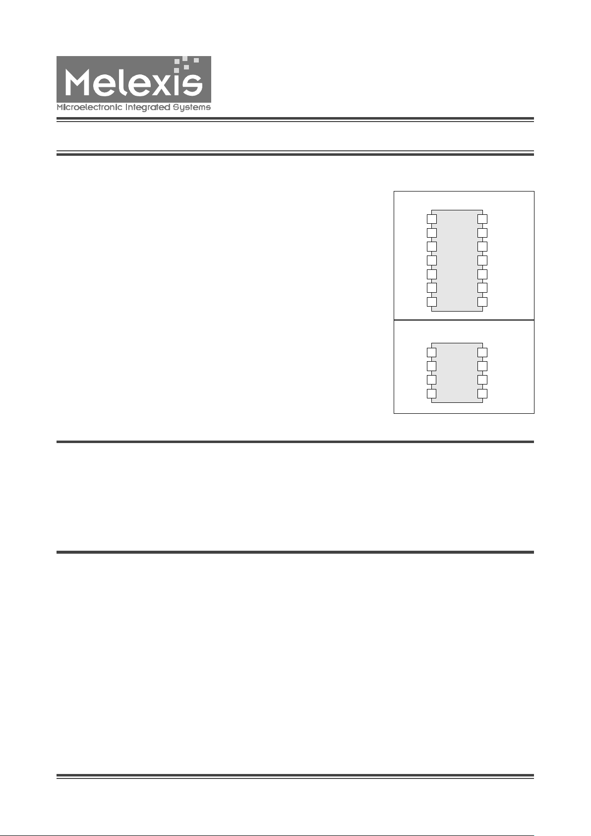
Pin Diagram
SOIC14NB
TH3044
1
VCC
GND
RXD
NRXD
BUS
VBAT
SEN/STA
TxD
14
13
12
11
10
9
87
6
5
4
2
3
TH3044
1
VCC
GND
RXD
NRXD
BUS
VBAT SEN/STA
TxD
8
7
6
54
2
3
SOIC 8
TH3044
K-Bus Interface
www.melexis.com
Page 2 Datasheet Rev 1.1 July 2001
All voltages are referenced to ground (GND). Positive
currents flow into the IC. The absolute maximum ratings
(in accordance with IEC 134) given in the table below are
limiting values that do not lead to a permanent damage
of the device but exceeding any of these limits may do
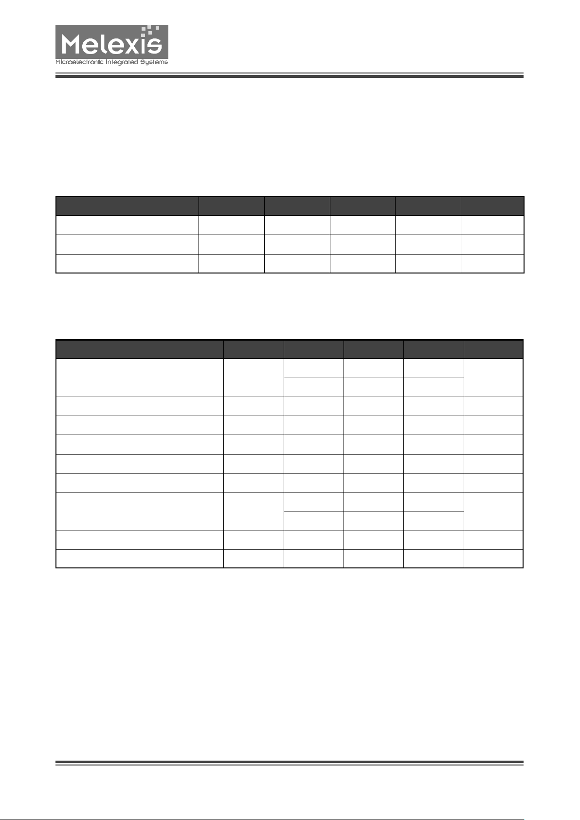
Electrical Characteristics
Absolute maximum ratings
so. Long term exposure to limiting values may affect the
reliability of the device. Reliable operation of the TH3044
is only specified within the limits shown in ”Operating
conditions”
Operating Conditions
Parameter Symbol Min Typ Max Unit
Battery Voltage V
BAT
6 16 V
Supply Voltage VCC 4.5 5.5 V
Operating Temperature TA -40 125 °C
Parameter Symbol Condition Min Max Unit
Battery Voltage V
BAT
-0.3 30
V
T ≤ 500 ms
40
Battery Current I
BAT
20 mA
Supply Voltage VCC 7 V
Supply Current ICC 10 mA
Input Voltage SEN/STA,TxD VIN -0.3 VCC+0.3 V
Input Current SEN/STA, TxD IIN -10 10 mA
Input Voltage BUS V
INBUS
-16 30
V
T ≤ 500 ms
40
Output Current RxD, NRxD I
OUT
-10 10 mA
Operating Temperature TA -40 125 °C

TH3044
K-Bus Interface
www.melexis.com
Page 3 Datasheet Rev 1.1 July 2001
Static Characteristics
VDD= 4.5 to 5.5V, V
Bat
= 6 to 16V, T
amb
= -40°C to +125°C, unless otherwise specified
Parameter
Symbol Condition Min Typ Max Unit
Supply
Power-on-reset Threshold VCC V
CCPOR
3.0 4.0 V
Power-on-reset Threshold VBAT V
BATPOR
3.0 4.5 V
Quiescent Current, ICC + IBAT I
CCBAT
VCC = 5V, VBAT = 12V,
BUS, TxD, SEN/STA, RxD
and NRxD open
50
µA
TxD, SEN/STA, RxD, NRxD
Pull-up Current TxD Ipu -330 -250 -170
µA
Pull-down Current SEN/STA I
pdSEN
170 250 330
µA
Pull-up Current SEN/STA I
puSEN
-330 -250 -170
µA
Input Voltage Low TxD, SEN/STA VIL 0.25 VCC
Input Voltage High TxD, SEN/STA VIH 0.75 VCC
Output Voltage Low RxD, NRxD VOL I
OUT
= 1 mA 1 V
Output Voltage High RxD, NRxD VOH I
OUT
= 1 mA VCC -1.0 V
BUS
Input Voltage Low BUS VIL 0.45 V
BAT
Input Voltage High BUS VIH 0.55 V
BAT
Hysteresis Input Voltage V
HYS
50 mV
Input Resistance BUS R
IN
V
BAT
= 0..40V 400 600 1500
kΩ
V
BAT
= 0..40V, TA = 85°C 1300
kΩ
V
BUS
= 12V 60
kΩ
Output Voltage BUS V
BUS
VBAT = 12V,
SEN/STA = Low,
I
BUS
= 40mA
1.2 V
I
BUS
= 25mA 1.0 V
Output Sinking Current BUS (current
limiting)
I
LIM
V
BUS
> 3.5V 40 110 mA
Output Sinking Current BUS (before fold
back)
I
BUS
180 mA
 Loading...