

MELEXIS MLX90805S Datasheet
Featur es an d Be n efi ts
g
y
g
(
g
y
y
g
g
q
y
g
y
g
y
y
y
g
g
q
g
g
g
g
“Soft Start” Eliminates Current Surges
rated Design Eliminates External Components
Inte
Drives Virtuall
Any Resistive or Inductive Load
Built–in Thermal Protection
ital Design For Stable Triac Contro l
Di
Immune to Lifetime and Thermal Drift
Low Power Cons umption
50Hz/60Hz Operation
Applications
AC Light Dimmer
Soft-Start AC Motor Controller
Variable-Speed AC Motor Controller
MLX9 0805
Intelligent Triac Controller
Ordering Information
Part No. Temperature Suffix Package version Temperature Range
MLX90805 S A -x 0C to 85C
MLX90805 S L -x 0C to 85C
The customer specific version code
the end of the orderin
number.
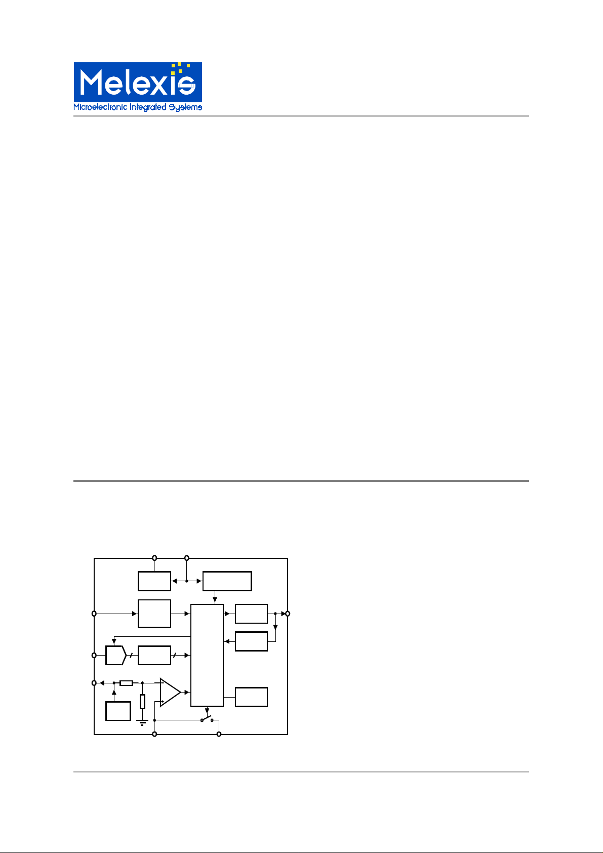
Functional Diagram
Vss Vdda
90805
Power monitorin
and reset
Logic
ZCD
SET
Vref
ADC
Vref
Voltage
regulator
zero
crossin
detector
Lookup
ROM
Vref/2
COMP
defining the options) is indicated with 1 character at
Description
The MLX90805 is a power control IC ideall
resistive or inductive load
ned primarily for starting and
hts.
purpose is to provide a “soft start”
current inrush. The triac is
changing the option bits.
function of the 90805 is proper
uency locked loop for
Triac driver
Auto
retriggerin
Options
for control of an
ulated by a triac.
re
The chip was desi
speed control of AC motors, but will work e
with an
Incandescent li
The c hip’s pr i m ar
for a motor , prev entin
controlled b
maximum power. Start rate can be varied from 0.5
sec. to 3 sec, b
The secondar
nition of the triac for inductive and resistive loads,
i
while keepin
minimum.
Added features include a fre
stable i
Inductive or resistive load such as
a linear “ramp” from minimum to
the triac’s current consumption to a
nition point.
suited
ually well
THP FB
MLX902xx Name of Sensor Rev Y.X 22/Aug/98 Page 1
MLX90805 Intelligent Triac Controller Page 1 Rev 1.2 17/May/00
MLX9 0805
Intelligent Triac Controller
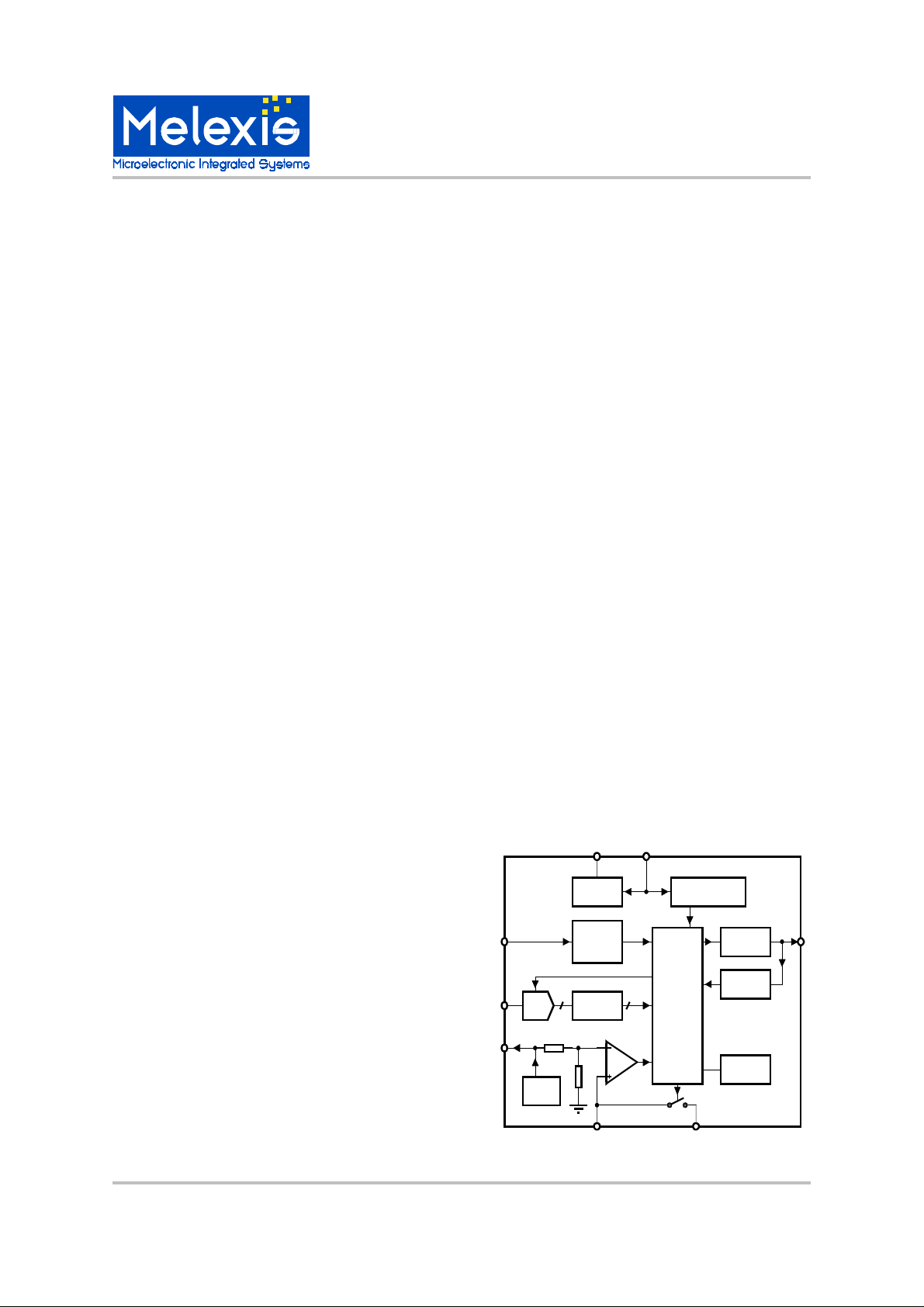
Description of Block Diagram
Voltage Regulator
The chip is supplied from the AC line voltage, by a
half wave rectifi er. The voltage at pin VDDA is limited
to ~ 15.5V. The digital part and some of the peripheral blocks are supplied by internally generated VDD
~ 5V.
Analog Power on Reset
This block tracks the voltage at VDDA, and permits
generation of firing pulses for the triac only if VDDA >
~13V. It is considered otherwise that the motor is not
properly supplied by the mains.
Oscillator
There is an on chip oscillator. All timing constraints
inside the chip are derived from this clock.
FLL
A frequency locked loop circuit is implemented to
obtain a clock frequency from a current controlled
oscillator, by using the mains frequency as a reference. A successive approximation algorithm is used
at start up to minimize the time for the oscillator adjustm ent.
Reference Voltage
This voltage is used to supply the external potentiometer for th e definition of different speed setti ngs.
Logic
This block performs all control functions to realize
time synchronization, smooth soft start, and proper
triac firing, so that motor runs at a defined speed.
Triac Driver
This output is able to drive directly a triac. It defines
the triac gate current and operates as current generator. There is no need of external resistor for current limitation.
Auto Retriggering
This block tracks if the triac is on after each firing
pulse. If the triac is off 20us after a firing pulse, a
new pulse is generated.
Thermal Protection
The chip is able to supply an external protection circuitry, typically an NTC resistor with reference resistor , to track the ambient temperature. If the vol tage at
THP equals Vref/2 the protection is activated and
the chip sets the firing angle defined by the value in
ROM address 1. A resistor connected to pin FB can
introduce hysteresis in the detection level.
Options
Thi s bl ock def i nes di ff eren t mo des of t he chi p o per ation.
ADC
The analog signal from the potentiometer, which defines the s peed s etti ng, i s tra nsfer red into digital by a
4-bit ADC. The reference for the converter is the voltage u sed to supply the p otentiometer.
90805
Vss Vdda
Voltage
regulator
Power monitoring
and reset
ROM
The d igital words from the A DC act as the a ddress of
a ROM table in whi ch th e different f iri ng angles are
programmed. This means that 16 different firing angles can be selected.
ZCD
SET
ADC
zero
crossing
detector
Lookup
ROM
Logic
Triac driver
Auto
retriggering
Zero Cross
Vref
Vref/2
COMP
THP FB
Options
This block detects the moments when mains voltage
Vref
crosses zero level. An accurate detection allows
good synchronization, so firing pulses driving the
triac can be generated at the right moment.
MLX90805 Intelligent Triac Controller Page 2 Rev 1.2 17/May/00
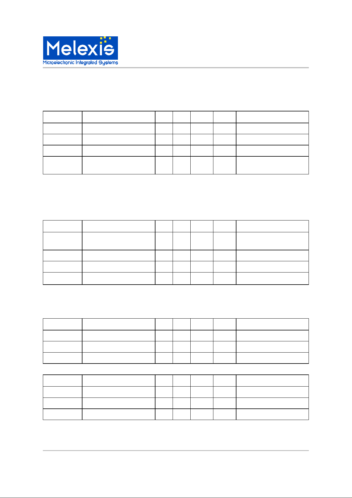
MLX90805 Electrical Specifications
Symbol
Description
Min Typ Max Unit Condition
Tamb
Ambient temperature
0 85 °C
Tch Maximum chip temperature
150 °C
Rth Thermal resistance
110
°C/Ω DIP8 or SOP8 package
IDDAm
Maximum allowed source su
p-
ply current
10 mA
Drivers off, all the current flows
in the chip
Symbol
Description
Min Typ Max Unit Condition
VDDA
Voltage applied at the supply
pin 14 16 18 V IDDA = 5mA
VDD Internal 5V supply
4.6 5.0 5.4 V
IDDA Current consumption
3 mA
VDDA = 14V
VREF
For external circuitry
4.6 5 5.4 V IREF = 8mA
g
Symbol
Description
Min Typ Max Unit Conditions
Vdporh
High level threshold
2.5 V Vdporl
Low level threshold
2.0 V Vdphyst
Hysteresis
0.5 V
Symbol
Description
Min Typ Max Unit Condition
Vaporh
High level threshold
12 13 14 V Vaporl
Low level threshold
9 10 11 V Vaphyst
Hysteresis
2 3 4 V
Environmental Conditions
Analog Fea tures
Power Sup ply
High voltage supply should be applied between VDDA and VSS.
MLX9 0805
Intelligent Triac Controller
Power On Reset
This block ensures a correct sta r t of the digital part.
The reset si
MLX902xx Name of Sensor Rev Y.X 22/Aug/98 Page 3
MLX90805 Intelligent Triac Controller Page 3 Rev 1.2 17/May/00
nal goes up for VDD > Vdporh and down for VDD < Vdporl.
MLX9 0805
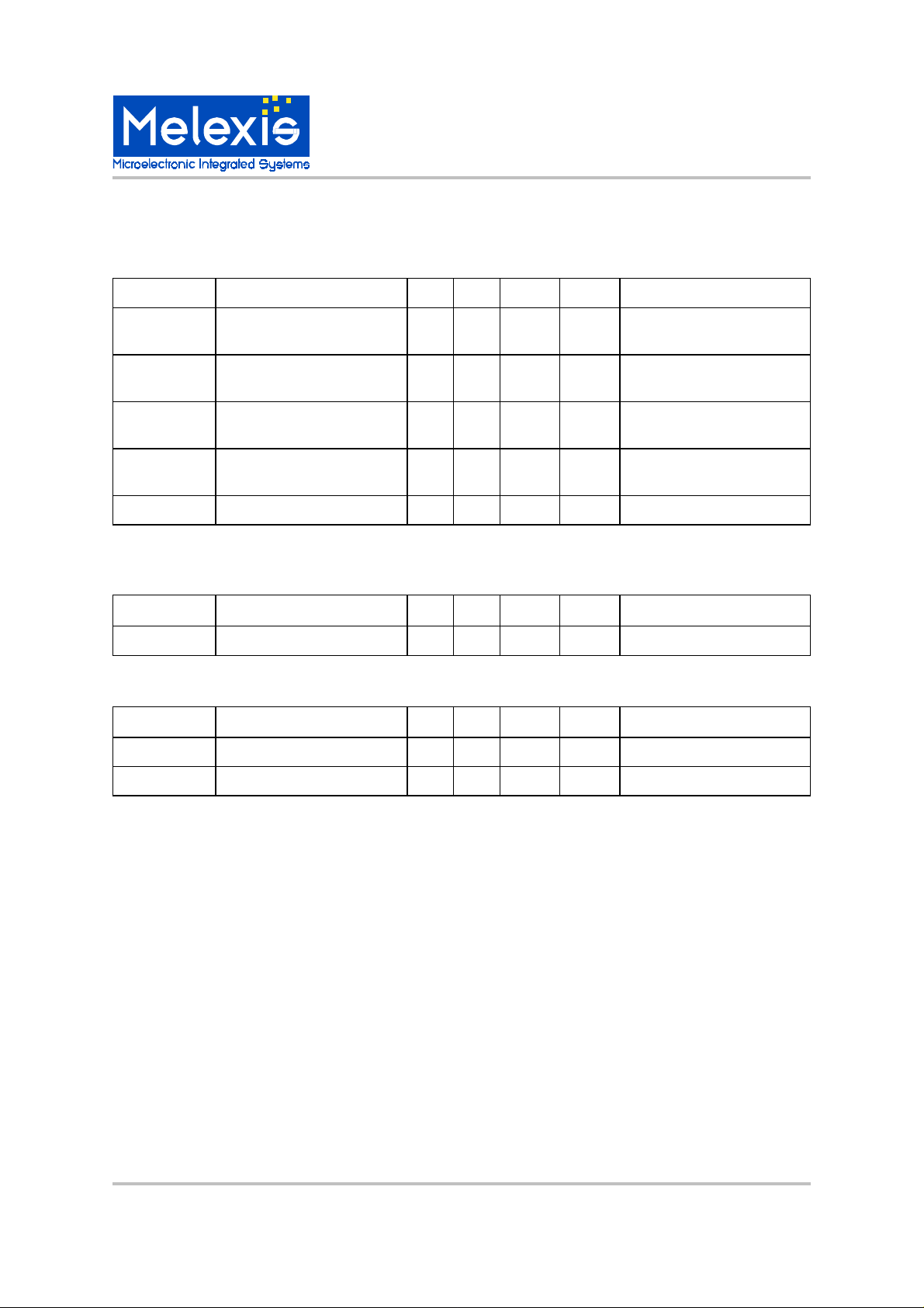
Symbol
Description
Min Typ Max Unit Conditions
Vzc1h
High level threshold 1
VDDA
+0.5 V Vzc1l
Low level threshold 1
VDDA
-
0.5 V Vzc2h
High level threshold 2
VDDA
-
1.5 V Vzc2l
Low level threshold 2
VDDA
-
2.5 V Rzc External resistor
470
kΩ
Vline = 230VAC typ
Symbol
Description
Min Typ Max Unit Conditions
ITRG Triac gate current
30 60 90 mA
VDDA > Vaporh
Symbol
Description
Min Typ Max Unit Conditions
Resolution
4
bits
VREF
Reference voltage
4.6 5 5.4 V
Intelligent Triac Controller
Zero Cross Detector
This detector contains two comparators with hysteresis. The first comparator has its reference at VDDA. The
reference of the second one is VDDA-1V.
Triac (Ignition) Driver
This driver operates as a current generator to fire the triac ON.
ADC
MLX90805 Intelligent Triac Controller Page 4 Rev 1.2 17/May/00
 Loading...