

MELEXIS MLX90804S Datasheet
MLX902xx Name of Sensor Rev Y.X 22/Aug/98 Page 1
MLX9 0804
Speed regulator for universal motors
MLX90804 Speed regulator for universal motors Page 1 Rev 1.0 30/Jun/00
Featur es an d Be n efi ts
•
Low cost - minimal external components
•
In PDIL8, PSOP8 or Chip-on-board
•
50/60Hz operation
•
Robust digital design:
•
Offering stable triac control
•
Eliminating variations due to changes in analogue param eter s
•
No aging and temperature influences
•
True PI speed regulator
•
No external calibration or adjustment required
•
Low power consumption
•
Suited for driving resistive and inductive loads
•
Pulse input to measure the motor speed with a low cost coil or a hall sensor
•
Motor current s ensing for power limitation
•
Adaptable to specific motor and application requirements by mask programming
Applications
Universal motor control applications that require true speed regulation, such as used in
blenders, mixers, kitchen appliances, drills, etc
Ordering Information
Part No. Temperature Suffix Package version Temperature Range
MLX90804 S A -x 0C to 85C Automotive
The customer specific version code
(
defining the options) is indicated with 1 character at the end of the ordering
number.
Description
The MLX90804 is a power control IC for controlling
the speed of AC motors b
y
means of a triac. The
speed settin
g
is done by applying a ratiometric
volta
g
e at pin SET (usually by means of a
potentiometer
)
. This speed setting is compared with
the pulse rate at the SPD input. The input is
compatible with inductive and ma
g
netic detectors.
The c alcul atio n of the r e
q
uired phase angle is done
with a PI re
g
ulator, which is fully digital.
A soft start function is implemented to eliminate hi
g
h
current peaks at startup. Also available are an
overload and overspeed protection.
The build in Fre
q
uency Locked Loop compensates
for variations in the mains fre
q
uency giving a stable
fre
q
uency independent trigger control .
Several parameters can be ad
j
usted by mask
pro
g
ramming: minimum and maximum speed, soft
start dela
y, g
ain settings of the PI r egulator, …
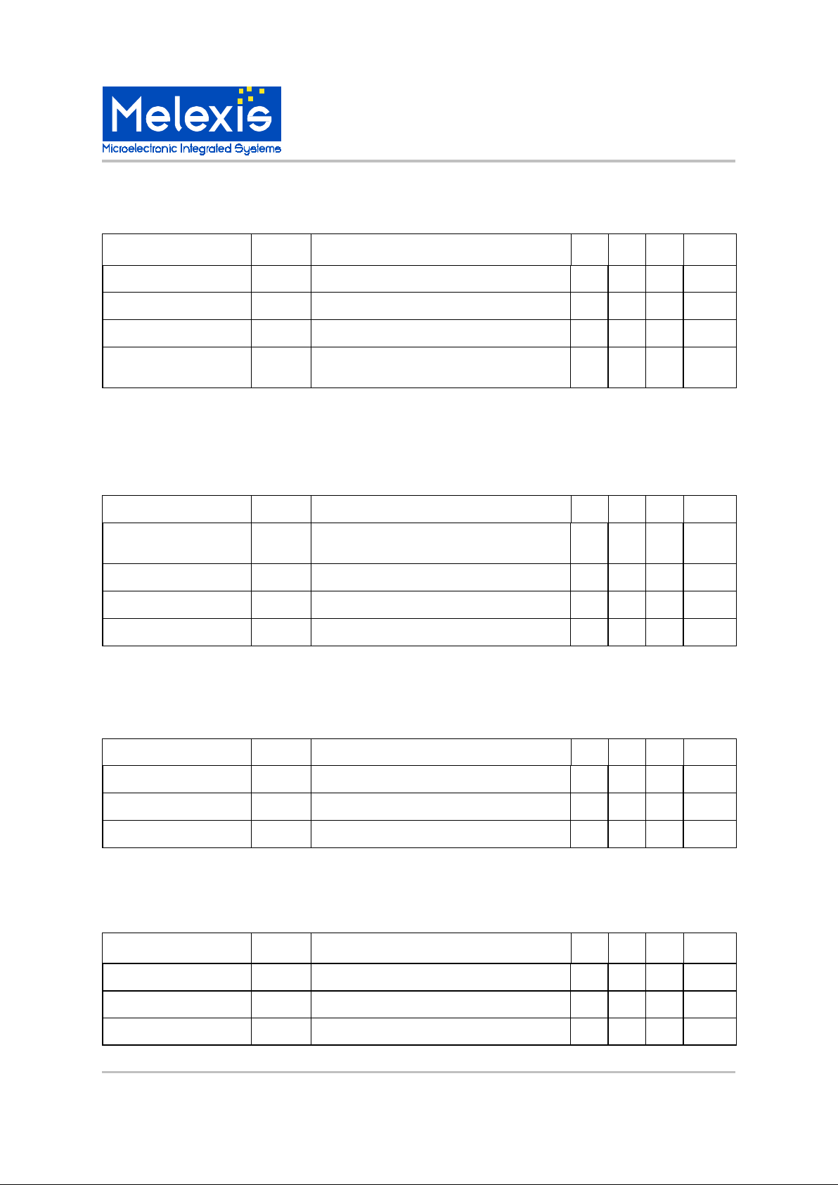
Functional Diagram
PLL
Control
lo
g
ic
ADC
Triac
drive
90804
SET
VDD
VSS
SYN
SPD
TRG
Gate
sensin
g
Zero
crossin
g
detector
Oscillator
Voltage
re
g
ulator
VDD1

MLX9 0804
Speed regulator for universal motors
MLX90804 Speed regulator for universal motors Page 2 Rev 1.0 30/Jun/00
General Description
Speed Regulator
The speed is regulated by a PI regulator with
programmable parameters Kp and Ki.
Speed Measurement
The s peed is measu red eit her b y a coil or by a hal l
sensor with digital output. The type of sensor can be
defined by mask option. The sensor must be located
close to a cylindrical magnet. The number of pole
pairs can be programmed.
Speed Setting
The speed is selected by applyi ng a voltage at pin
SET. The voltage at this pin is fed into an ADC
(referenced to VDD) and is converted to a 4 bit
val ue. This val ue is the address of a ROM table in
which the different speeds are programmed. This
means that 16 di f feren t speeds can be selected.
The relation between voltage at input SET and the
corresponding speed does not need to be linear. It
can be freely chosen.
Soft Start
A soft start procedure is activated at start up and is
implemented to guarantee a smooth startup of the
motor under all conditions. At very low speed the
speed can not yet be measured and therefore
several actions are taken so that the PI regulator can
smoothly take over once the speed has increased
sufficiently. The soft start function is configurable
with the o ption mask.
Just af ter a pplying p ower to the electronics there is a
delay time until the motor starts movement. The
maximum allow a ble de la y time is 300 ms.
Speed Set Ramping
At any time when the speed setting is changed to a
new speed, the change is internally generated with a
ramp function to optimize the transient behavior of
the PI regulator. This ramp f unction is configurable
with the o ption mask.
Main Switch
It is possible to program one or more speed settings
with a zero speed. This will stop the motor. However
for security reasons it might be considered to
combine this setting with a switch to disconnect
mot or and/or elect r onics from t he mai ns.
Overload shutoff feature
625 ms after starting the motor (i.e. selecting a
speed setting different from 0 rpm) the following
function will be enabled: if the speed of the motor
gets lower then a programmable value SLIM for
longer then 320 ms, the motor speed is permanently
set to 0 rpm. As a consequence the first possible
timeout to recognize a blocked motor after start will
be approximately 1 sec.
This state can only be left by disconnecting the
power from the electroni c circu it.
Overspeed shutoff feature
If the speed of the motor gets higher than a
pro gramm able val ue SLI MA for l onger t hen 320m s,
the s el ect ed speed is perm an ent ly set to 0 rpm . Thi s
state can only be left by disconnecting the power
fr om the elect r onic s.
MLX902xx Name of Sensor Rev Y.X 22/Aug/98 Page 3
MLX9 0804
Speed regulator for universal motors
MLX90804 Speed regulator for universal motors Page 3 Rev 1.0 30/Jun/00
MLX90804 Electrical Specifications
DC Operating Parameters T
A
= 0oC to 85
o
C Parameter
Symbol
Test Conditions
Min Typ Max Units
Ambient temperature
Tamb
0 85 °C
Maximum chip temperature
Tch
150 °C Thermal resistance
Rth PDIP8 package
110
°C/W
Maximum allowed source
supply current
IDD4m
Drivers off, all the current flows in the chip
10 mA
Power supply
The 90804 suppl
y
pin (VDD1) must be connected by external series resistors and a rectifier diode to the AC
line. An internal zener function limits the volta
g
e at VDD1 to approximately 16V. For proper operation a decou-
plin
g
capacitor must be connected between VDD1 and VSS.
Parameter
Symbol
Test Conditions
Min Typ Max Units
Voltage applied at the su
p-
ply pin
VDD1
IDD1 = 5mA
14 16 18 V Internal 5V supply
VDD
4.6 5.0 5.4 V Current consumption
IDD1 VDD1 = 14V
0.7 mA
For external circuitry
VEXT
IEXT = 8mA
4.5 5 V
Parameter
Symbol
Test Conditions
Min Typ Max Units
Hysteresis
Vdphyst
0.5 V
Analog Power-On Reset
This block tracks the volta
g
e applied at VDD1. The t r iac firing is permitted if VDD1 > Vaporh and is stopped when
VDD1<Vaporl.
Parameter
Symbol
Test Conditions
Min Typ Max Units
High level threshold
Vaporh
13 V Low level threshold
Vaporl
10 V Hysteresis
Vaphyst
2 3 4 V
Power on Reset
Thi s blo ck ensu res a corr ect st art o f th e di
g
it al par t. Th e reset signal (DPORB) goes up for VDD>Vdporh and
down for VDD<Vdporl.
High level threshold
Vdporh
2.5 V
Low level threshold
Vdporl
2.0 V
MLX9 0804
Speed regulator for universal motors
MLX90804 Speed regulator for universal motors Page 4 Rev 1.0 30/Jun/00
Zero crossing detector
This detector contains two comparators with hysteresis. The first comparator has reference at VDD1. The reference of the second one is VDD1-1V. Both outputs ZC1 and ZC2 are HIGH during positive half wave of the mains
and LOW during negative half wave of the mains.
Parameter
Symbol
Test Conditions
Min Typ Max Units
High level threshold 1
Vzc1h
Referenced to VDD1
0.5 V
Low level threshold 1
Vzc1l
Referenced to VDD1
-
0.5 V
High level threshold 2
Vzc2h
Referenced to VDD1
-
1.5 V
Low level threshold 2
Vzc2l
Referenced to VDD1
-
2.5 V
Speed measurement
The c hi p has an i np ut SP D to mea sur e the m ot or sp eed. It is possi b le to c onn ect a l ow co st i nduc tor (b etw een
SPD and VSS) or a hall sensor with digital output. . The type of sensor can be defined by mask option. In case
of the use of a coil the input levels are defined in t he table below. In case of the use of a hall sensor, the levels
are cmos compatible.
Parameter
Symbol
Test Conditions
Min Typ Max Units
High comparator level
SPDHI
80 mV Low comparator level
SPDLO
-80 mV
Note:
When used with a coil, the input voltage is on chip limited to approximately –280mV. However the current injected or pulled out of this pin should not increase above 1 mA.
When used with a hall sensor, the SPD input does not have an internal pull up resistor.
Ignition driver
This driver operates as a current generator to fire the triac.
Parameter
Symbol
Test Conditions
Min Typ Max Units
Triac gate current
ITRG VDD1 > Vaporh
30 60 90 mA
ADC
This is a 4-bit ADC.
Parameter
Symbol
Test Conditions
Min Typ Max Units
Resolution
4
bits Reference voltage
Vref VDD
 Loading...