

MELEXIS MLX90720S Datasheet
MLX902xx Name of Sensor Rev Y.X 22/Aug/98 Page 1
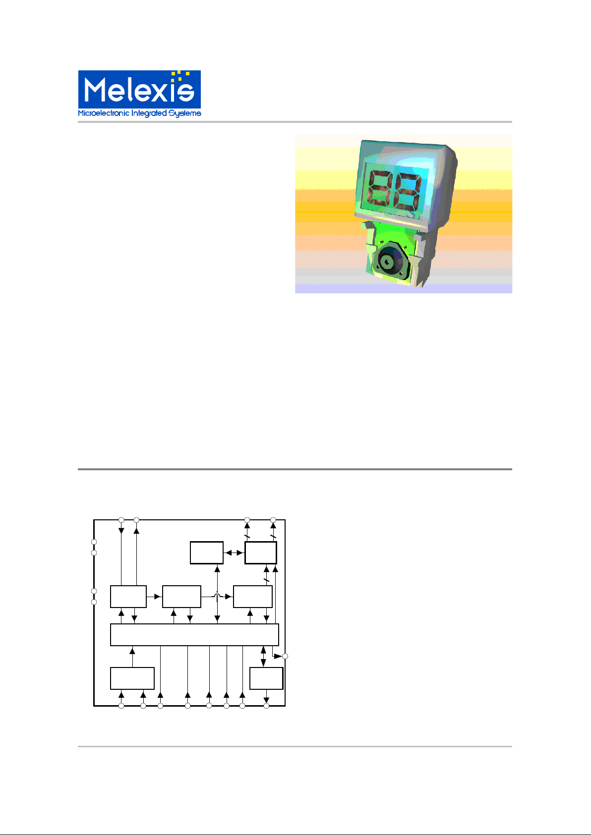
MLX90720
One Button Timer
MLX90720 One Button Timer Page 1 Rev 1.0 30/Nov/00
Features and Benefits
Flexible timer chip thanks to several
configurations and options
Low cost – minimal external components
Low power consumption guarantees a
long operation life on a low cost
1.5V button cell
COB (Chip-On-Board) package technology
for compact and low cost implementation
Accurate timing based on low power crystal oscillator
Output for driving an external transistor
Applications
Autonomous kitchen timer
Parking timing reminder key ring
Ordering Information
Part No. Temperature Suffix Package Temperature Range
MLX90720 S die 0C to 85C
Description
The electronic timer device is powered by a 1.5V
button cell, is programmable from 0 to 99 minutes,
with 2 beep cycles at the end of countdown. The
countdown mode is indicated with a blinking display.
The timer is provided with an internal memory that
allows the memorization of the last programmed
time. The chip automatically enters sleep mode when
not in use. The device can be used in several
configurations and has several options, which are
described below.
The chip is designed to be used with a dual
backplane LCD.
The timer chip has an output ( RELO ) for driving an
external low power NPN bipolar transistor. This
transistor could be used for driving a switching
element (relay). It can be connected directly (base to
RELO) or through a resistor from 100 to 200 ohms.
Functional Diagram
Control
SoundKey logic
Seconds
counter
Record
memory
Timebase
Min/
Half-min
Display
driver
Bi SEGi
XOUT
XIN
CAP1
CAP2
VDD
VSS
BUT1 BUT2 TEST REC BUZMTST MSEL
RELO
90720
FST

MLX90720
One Button Timer
MLX90720 One Button Timer Page 2 Rev 1.0 30/Nov/00
General Description
The electronic timer is a self-powered device,
programmable from 0 to 99 minutes, with ringing at
the end of countdown. The timer has an internal
memory which stores the last programmed time.
An auto shut-off and a validation of the countdown
(blinking display) are also provided.
The chip is designed to be used with a 2 backplanes
LCD :
Operation Voltage 3V
Driving condition 1/2 Duty, 1/2 Bias
The timer chip has an output ( RELO ) for driving an
external low power NPN bipolar transistor and a
buzzer driver output.
RELO output
The timer chip has an output ( RELO ) for driving an
external low power NPN bipolar transistor. This NPN
transistor could be used for driving a switching
element (relay). It can be connected directly (base to
RELO) or through a resistor from 100 to 200 ohms.
Buzzer output
The chip has an output driver to drive a magnetic
transducer. The frequency generated at this output is
2048 Hz.
Configurations
4 different configurations are possible and are
defined according to the following table:
1: connected to Vdd.
0: connected to Vss.
Configuration 1: Minutes mode (a) : countdown in
minutes and the last minute is displayed in seconds.
Configuration 2: Minutes mode (b): countdown in
minutes and the last minute is not displayed in
seconds.
Configuration 3: Minutes mode (c) : countdown in
minutes with a 0.5 min. step from 10 min to 1 min
and the last minute in seconds.
Configuration 4: Seconds mode.
Options
In each configuration two options are possible: the
restore memory option and the second fast
increment option.
The restore memory option is available in one button
version (OBT: One Button Timer) or two button
version (TBT: Two Button Timer) (see functional
description on following pages). With this option the
last programmed time can be restored.
The chip operates in OBT mode with restore
memory, if pin REC is connected to VDD and
operates in TBT mode, if REC is connected to VSS
and button 2 is bonded. When the restore function is
not used, REC is connected to VSS and button 2 is
not used.
The TBT also has more flexibility in programming
mode, as the time can not only be increased but also
decreased.
The second fast increment option can be chosen to
have two increment speeds in programming mode to
set the desired time. The chip operates in this mode
if pin FST is connected to Vdd.
Modes
The timer has 6 modes of operation:
Wake up mode
Programming mode
Count down mode
Ringing mode
Wait mode
Power down mode
The timer is always in one of these modes.
Functional description
The following paragraph describes the functionality
of the asic in configuration 1, but with different
options.
Basic OBT
The basic One Button Timer has no second button,
no restore memory and no second fast increment
option.
Wake up:
The first press enables the wake up of the chip within
two seconds (debouncing + startup of the oscillator).
The value 00 is displayed (non-blinking) and the chip
enters programming mode.
Programming mode:
The programming of the timer is implemented with
one button. In this mode the display doesn't blink.
MTST MSEL
Configuration 1 0 0
Configuration 2 1 0
Configuration 3 0 1
Configuration 4 1 1

MLX902xx Name of Sensor Rev Y.X 22/Aug/98 Page 3
MLX90720
One Button Timer
MLX90720 One Button Timer Page 3 Rev 1.0 30/Nov/00
If the button is pressed and released (short press),
the single increment mode is selected, in which the
time value is incremented with one Least Significant
Digit, which corresponds to 1 minute.
If the button is pressed for more then 1 second, the
chip enters the fast increment mode, increasing the
value of the programmed time with a speed of 4 LSD
per second. If the button is released, the single
increment mode is selected, in which the time value
is incremented with one LSD on each cycle of pressrelease. The timer can switch back and forth
between single and fast increment mode.
When exceeding 99 minutes the timer jumps to 00
minutes.
During the programming mode, reset is not available.
If the button is released for more than 2 sec and the
display is not at 00 the chip enters countdown mode.
When 00 is displayed and no button has been
pressed for more than 45 sec. the chip enters power
down mode.
Countdown mode:
If the timer is in programming mode, and the loaded
value is different from 00, when the button is
released for more than 2 seconds, the countdown
starts. The countdown mode is indicated with a
blinking display with a cycle of one second (0.5 sec's
on, 0.5 sec's off). The countdown of the last minute
is diplayed in seconds: 1min, 59s, 58s,...0s.
At the end of the countdown, the chip enters ringing
mode.
Reset is possible during countdown by pressing the
button for more than 1 second. In this case the chip
enters programming mode again, displaying 00.
Ringing mode:
At the end of countdown, a ringing is produced,
which warns the user :
- 10 groups of 3 sounds, total duration 10 seconds
- a delay of 20 seconds
- 10 groups of 3 sounds, total duration 10 seconds
The second group of sounds starts 30 seconds after
the end of countdown. In this way a time with a
resolution of 30 seconds can be achieved.
At the end of the cycle, the timer value 00 is returned
and programming mode is entered.
During the ringing mode, the display continues to
blink. The ringing mode can be interrupted by
pressing the button (short or long press). In this case
the chip enters programming mode. The value 00 is
shown.
Power down mode:
When the chip enters in this mode the oscillator and
the display are disabled and the current consumption
is minimized.
Note that waiting mode is not available.
OBT with second fast
increment
The basic One Button Timer can have the second
fast increment option. This has only an influence
during programming mode.
Wake up:
The first press enables the wake up of the chip within
two seconds (debouncing + startup of the oscillator).
The value 00 is displayed (non-blinking) and the chip
enters programming mode.
Programming mode:
The programming of the timer is implemented with
one button. In this mode the display doesn't blink.
If the button is pressed and released (short press),
the single increment mode is selected, in which the
time value is incremented with one Least Significant
Digit, which corresponds to 1 minute.
If the button is pressed for more than 1 second, the
chip enters the fast increment mode, increasing the
value of the programmed time with a speed of 4 LSD
per second. If the button is pressed for more then 5
seconds, the second fast increment mode is
activated, increasing the time with 8 LSD per second.
If the button is released, the single increment mode
is selected, in which the time value is incremented
with one LSD on each cycle of press-release. The
timer can switch back and forth between single and
fast increment mode.
When exceeding 99 minutes the timer jumps to 00
minutes.
During the programming mode, reset is not available.
If the button is released for more than 2 sec and the
display is not at 00 the chip enters countdown mode.
When 00 is displayed and no button has been
pressed for more than 45 sec. the chip enters power
down mode.
Countdown mode:
If the timer is in programming mode, and the loaded
value is different from 00, when the button is
released for more than 2 seconds, the countdown
starts. The countdown mode is indicated with a
blinking display with a cycle of one second (0.5 sec's
on, 0.5 sec's off). The countdown of the last minute
is diplayed in seconds: 1min, 59s, 58s,...0s.
At the end of the countdown, the chip enters ringing
mode.
Reset is possible during countdown by pressing the
button more than 1 second. In this case the chip
enters programming mode again, displaying 00.

MLX90720
One Button Timer
MLX90720 One Button Timer Page 4 Rev 1.0 30/Nov/00
Ringing mode:
At the end of countdown, a ringing is produced,
which warns the user :
- 10 groups of 3 sounds, total duration 10 seconds
- a delay of 20 seconds
- 10 groups of 3 sounds, total duration 10 seconds
The second group of sounds starts 30 seconds after
the end of countdown. In this way a time with a
resolution of 30 seconds can be achieved.
At the end of the cycle, the timer value 00 is returned
and programming mode is entered.
During the ringing mode, the display continues to
blink. The ringing mode can be interrupted by
pressing the button (short or long press). In this case
the chip enters programming mode. The value 00 is
shown.
Power down mode:
When the chip enters in this mode the oscillator and
the display are disabled and the current consumption
is minimized.
Note that waiting mode is not available.
OBT with restore memory
The basic One Button Timer can have the restore
memory option, which is operated with the same
button.
Wake up:
In OBT configuration, the first press enables the
wake up of the chip within two seconds (debouncing
+ startup oscillator).
If it is a short press, the value 00 is displayed (nonblinking), the chip enters programming mode.
If the button is pressed more than 1 sec., the restore
function is activated and the last programmed time is
displayed (non-blinking). During the first second, the
value 00 is displayed (non blinking). The chip enters
programming mode.
Programming mode:
The programming of the timer is implemented with
one button. In this mode the display doesn't blink.
If the button is pressed and released (short press),
the single increment mode is selected, in which the
time value is incremented with one least significant
digit (LSD), i.e. 1 minute.
If the button is pressed for more than 1 second, the
chip enters the fast increment mode, increasing the
value of the programmed time with a speed of 4 LSD
per second. The timer can switch back and forth
between single and fast increment mode.
When exceeding 99 minutes the timer jumps to 00
minutes.
During the programming mode, reset is not
available.
If the button is released for more than 2 sec and
the display is not at 00 the chip enters countdown
mode.
If the button is not pressed during 45 seconds the
chip enters power down mode.
Countdown mode:
If the timer is in programming mode, and the
loaded value is different from 00, when the button
is released more than 2 seconds, the countdown
starts. The countdown mode is indicated with a
blinking display with a cycle of one second (0.5
sec's on, 0.5 sec's off). The countdown of the last
minute is displayed in seconds: 1min, 59s,
58s,...0s.
At the end of the countdown, the chip enters
ringing mode.
Reset is possible during countdown by pressing
the button for more than 1 second. In this case the
chip enters waiting mode.
Ringing mode:
At the end of countdown, a ringing is produced,
which warns the user :
- 10 groups of 3 sounds, total duration 10 seconds
- a delay of 20 seconds
- 10 groups of 3 sounds, total duration 10 seconds
The second group of sounds starts 30 seconds
after the end of countdown. In this way a time with
a resolution of 30 seconds can be achieved.
At the end of the cycle, the timer value 00 is
returned and waiting mode is entered.
During the ringing mode, the display continues to
blink. The ringing mode can be interrupted by
pressing the button. A short press directly enters
waiting mode. A press of longer then 2 seconds
activates the restore function and programming
mode is entered with the restored time.
Waiting mode:
In this mode the timer value 00 is displayed and
the display is blinking. Pressing the button for more
then 2 seconds activates the restore function and
programming mode is entered with the restored
time. A short press of the button enters
programming mode at time 00.
If the button is not pressed during 45 sec the chip
enters power down mode.
Power down mode:
When the chip enters this mode the oscillator and
the display are disabled and current consumption
is minimized.
 Loading...