

MELEXIS MLX90711S Datasheet
MLX902xx Name of Sensor Rev Y.X 22/Aug/98 Page 1
MLX90711
Position/movement Sensing Auto-Shutoff
MLX90711 Position/movement Sensing Auto-Shutoff Page 1 Rev 1.0 15/Sep/00
Features and Benefits
Safety Auto shut off based on movement or position sensing.
Low cost – minimal external components.
Very reliable patented capacitive sensor,
insensitive to erosion and dust.
On chip calibrated timer.
Pdip8 or sop8 package.
Drives different relay types, including low cost
12V relays and most custom made relays.
Auto shut off status is indicated via a led.
Several timing options available.
Applications
Irons, fryers, ...
Ordering Information
Part No. Temperature Suffix Package version Temperature Range
MLX90711 S A -x 0C to 105C
MLX90711 S L -x 0C to 105C
The customer specific version code (defining the options) is indicated with 1 character at the end of the ordering
number.
Description
The Automatic Shut-Off is a safety system which
turns off the electrical power of a load based either
on a movement detection or a position detection.
This detection will be taken into account after a well
defined time delay. A typical application is the safety
feature in irons which will switch off the heating
element when the iron is left immobile for a well
defined period, which can be dependant on the
position. The state of the Auto Shut-Off can be
indicated with an led.
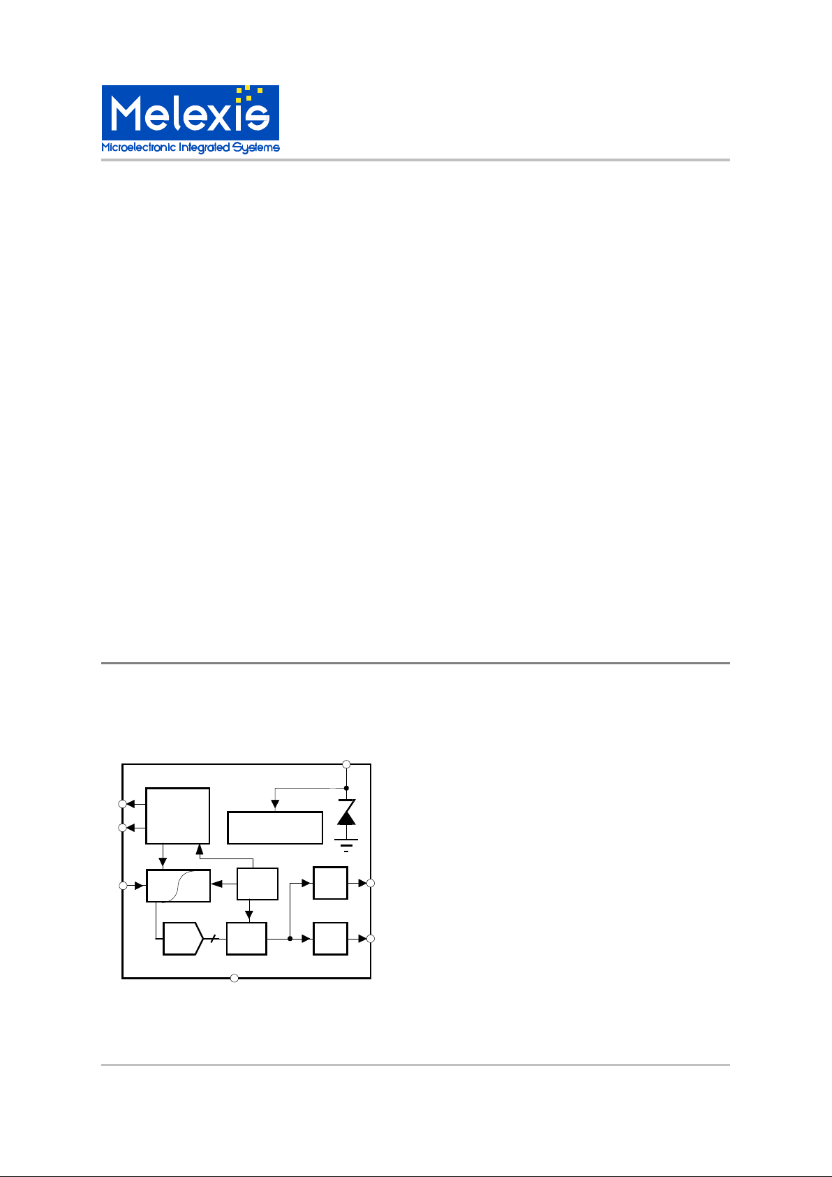
Functional Diagram
Regulator & bias
Sequencer
Osc
Relay
Logic
ADC
LED
VSS
VDD1
RD
LEDP
SUM
CA1
CA0
90711

MLX90711
Position/movement Sensing Auto-Shutoff
MLX90711 Position/movement Sensing Auto-Shutoff Page 2 Rev 1.0 15/Sep/00
Introduction
The Automatic Shut-Off is a safety system which
turns off the electrical power of a load based either
on a movement detection or a position detection.
This detection will be taken into account after a well
defined time delay. A typical application is the safety
feature in irons which will switch off the heating
element:
if the iron is connected to the mains and left
immobile in the ironing position for a time larger than
TH;
OR
if the iron is connected to the mains and left
vertically up on heel rest for a time larger than TV.
OR
if the iron is connected to the mains and left
vertically down on heel rest for a time larger than TD.
The heating of the iron is turned on again
immediately after detecting a different position (or
detecting a movement).
Sensing Principal
Melexis developed a new concept of Auto Shut-Off in
which the position or movement detection is realized
with a patented capacitive detection. This sensor
uses the movement of a ball, but the detection is
capacitive, and therefore, the system does not need
a conductive contact. Consequently, the system is
insensitive to erosion and dust.
The sensitivity of the asic is very high, and a ball with
a diameter as small as 3 mm can be used.
This detection system described in the following
section is protected by a patent (Patent European
application Nr. EP0589092; US application Nr.
US5627316).
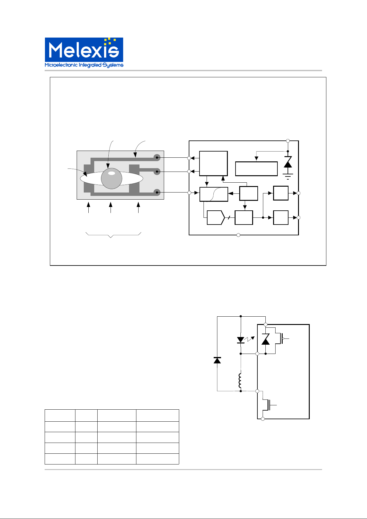
General Description
The detection is done based on the ratio of two
variable capacitors. These capacitors can be the
parasitic capacitances of a small conductive ball
placed on a cavity in the pcb. As the pcb is rotated in
its lenghty direction, the ball is running forwards and
backwards on the pcb. Copper tracks placed on the
PCB at the edges of the hole will be used as the
terminals of capacitors. We can define two
capacitors made up of 2 copper tracks with a
(conductive) ball in between. If the ball rolls just
between 2 copper tracks, the distance between the
copper tracks and the ball will decrease, thus
increasing their capacitance. The circuitry on chip
performs a measurement of the difference between
these 2 caps. It controls the sense terminals (CA0,
CA1, SUM), processes their data and drives 2
outputs: RD (to drive a relay) and LEDP (to drive an
led). The information from the detection system
results in a momentary down, up or horizontal
position. This information can be used to generate a
position detection or can be interpreted as a
movement detection.
When used as a position sensor, the output of the
sensor consists of 3 digital signals, indicating the
position of the sensor: the ball is in the middle
(horizontal), is at the front side (down) or is at the
end (up). The position of the ball is sensed every
15.6 msec. For this the analog output voltage of the
sensor circuit is sent to 3 comparators with
hysteresis. If the result is equal for 3 consecutive
samples, the corresponding digital signal (DOWN,
UP or HOR) becomes valid. This signal is used to
evaluate the Auto Shut-Off function. The Auto ShutOff is active only when UP remains high during a
time period larger than TV or when HOR remains
high during a time period larger than TH or when
DOWN remains high during a time larger than TD.
The signals UP, HOR and DOWN are debounced.
When the Auto Shut-Off is active the relay driver is
activated. Using a NC (normally closed) type relay,
this can switch off the power of the heating element.
When the module is moved, the ball can roll forwards
and backwards in such a way that the states UP,
HOR and DOWN never remain stable for a time
more than TV, TH and TD respectively and the relay
output is not activated.
As long as the vertical inclination is enough to keep
the ball in the "vertical" area, the state UP remains
active.
When used as a movement sensor the output of the
sensor has only one signal which indicates that the
position of the ball has changed. If this signal is
inactive for the predefined time period TASO, the
chip enters the Auto Shut-Off state. The position of
the ball is sensed every 15.6 msec. When the Auto
Shut-Off is active the relay driver is activated. Using
a NC type relay, this can switch off the power of the
heating element.
When the module is moved, the ball can roll forwards
and backwards and due to this the chip continuously
detects a change of state of the sensor.
Power On Reset
In the chip there is a block "Power On Reset" (POR),
which tracks the level of the power supply voltage
Vdd1 and defines the state of the chip.
If Vdd1 is less than the high POR level (PORHI) after
initial plugging into the mains, the chip is in the "reset
state". When Vdd1 becomes higher than the PORHI
level, the operation of the chip starts: start up
sequence, heating up and then the chip enters in
"normal operation mode".
If Vdd1 becomes less than the low POR level
(PORLO), (PORLO=PORHI-HYS), for more than
7.8msec the chip enters the "reset state".
MLX902xx Name of Sensor Rev Y.X 22/Aug/98 Page 3
MLX90711
Position/movement Sensing Auto-Shutoff
MLX90711 Position/movement Sensing Auto-Shutoff Page 3 Rev 1.0 15/Sep/00
Power down timing
After disconnecting the mains , the chip will reset:
- within typical 0.25sec when the coil is not activated
(iron is heating)
- within typical 2.5sec when the coil is activated (iron
is in ASO)
Relay and led driver options
The relay is driven by a pulsed signal instead of a
continuous signal. Consequently, the power
consumption is reduced.
The relay driver performs this feature. There are
four duty cycles available: 14.4%,16%, 28% and
31%. During 7.8 ms after the switching time , the
duty cycle is increased. This will give an increased
energy to the relay for a short time at the moment the
relay coil must change the state of the contact. The
switching time starts by applying the control voltage
on the coil of the relay. The values of the duty cycles
for the first 7.8 ms are in the table in brackets. The
switching frequency of relay and led are the same
and are typically 20.48KHz.
The type of relay should be normally closed (NC). A
NC relay is opened by applying the control voltage
on its coil and in this case the module is in Auto
Shut-Off mode.
Applications Example
PCB
Regulator & bias
Sequencer
Osc
Relay
Logic
ADC
LED
VSS
VDD1
RD
LEDP
SUM
CA1
CA0
90711
down
horizontal
up
copper track
cavity
ball
ball position
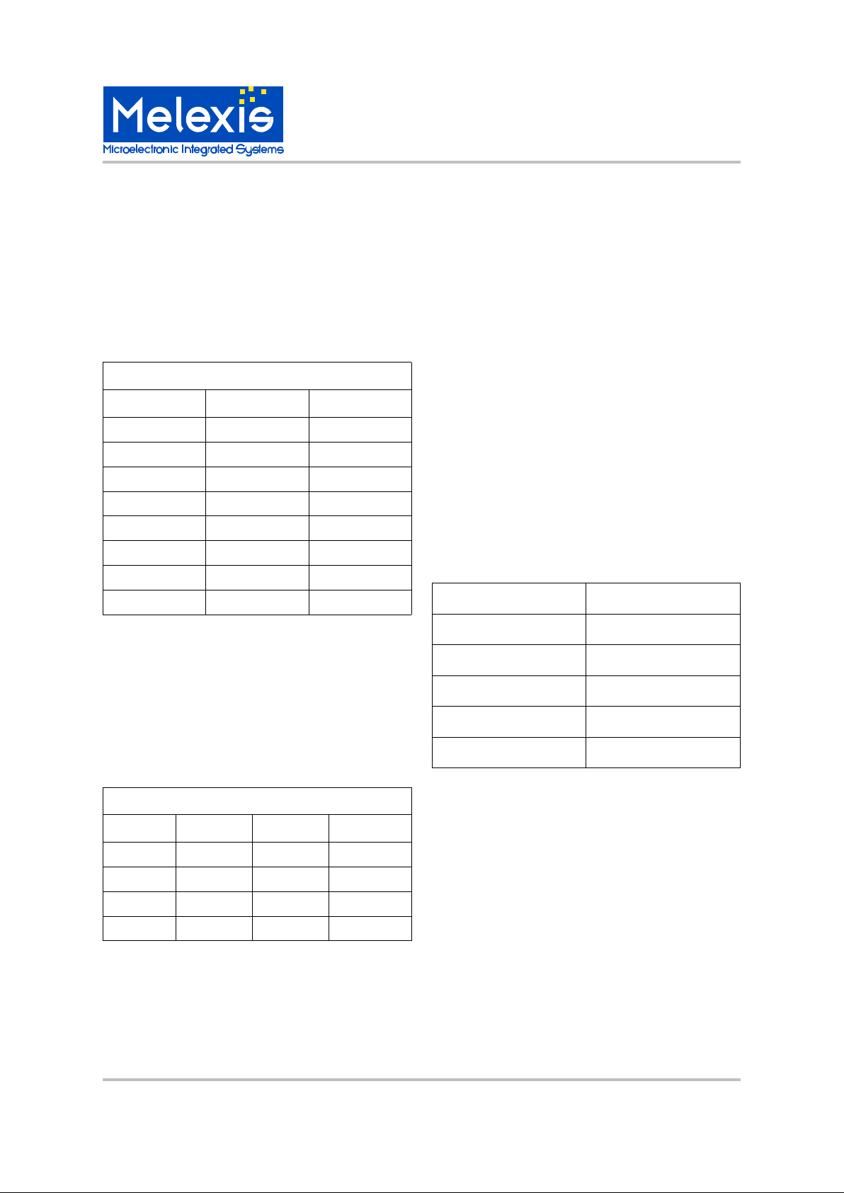
SRD1 SRD2 Relay DC Led DC
0 0 14.4%(28%) 14.4%(28%)
0 1 28%(43%) 28%(43%)
1 0 16%(31%) 16%(31%)
1 1 31%(48%) 31%(48%)
VSS
LEDP
VDD
1
90711
RD
Relay - Led output configuration
MLX90711
Position/movement Sensing Auto-Shutoff
MLX90711 Position/movement Sensing Auto-Shutoff Page 4 Rev 1.0 15/Sep/00
Movement Auto Shut-Off time
When used as a movement Auto Shut-Off module,
several timing options are available. All timings are
derived from the on chip oscillator and have thus the
same tolerance.
If the module is left immobile for a time longer than
TASO the auto shut-off function becomes active.
There is also an additional time period TADI. This
time is valid only in the vertical state and determines
the time between shut-off and the start of the led
blinking.
Position Auto Shut-Off
When used as a position Auto Shut-Off module,
several timing options are available. All timings are
derived from the on chip oscillator and have thus the
same tolerance.
Three different time delays can be defined: the
horizontal shut-off (TH), the vertical shut-off (TV) and
the down shut-off (TD).
Start up sequence
When connecting the asic to the AC line the asic first
passes through a startup sequence. The duration of
this sequence is 1.25 or 3.75 seconds depending on
the duration of phase 1. After the start up test the
normal function of the chip begins. This sequence
involves the following phases :
PHASE 0: The duration is a time period
“TS”, which incorporates the Power On Reset time
period. This time ‘TS” is typically 0.2 sec.
PHASE 1: The duration is 0.5 second or 3
seconds. This can be defined by the mask option
SPH1. During this phase the iron heats. The ASO
function is not active. The LED is off. The relay is
NC and the control voltage is not applied to its coil
during this phase.
PHASE 2: The duration is 0.75 second. The
ASO function is active. The iron is not heating. The
control voltage is applied to the coil of the relay
during this phase. The LED indicates that the ASO
function is active. Some additional information is
sent out by the led driver during this phase. This
information involves three frequency codes.
- the first code is the highest digital clock
(20.48kHz). The duration is 250ms.
- the second code is the inform ation of the
position sensor. The frequency depends on the
position of the module:
- the third code is the information of the
metal mask where the customer specific options are
defined. It is coded using one of five frequencies
(20kHz, 10kHz, 5kHz, 2.5kHz, 1.25kHz).
EMC
Thanks to a special algorithm the sensor is made
very insensitive to noise and AC line coupling.
ESD Precautions
Electronic semiconductor products are sensitive to
Electro Static Discharge (ESD).
Always observe Electro Static Discharge control
procedures whenever handling semiconductor
products.
position LED frequency (KHz)
UP 1.28
Between UP and HOR 2.56
HOR 5.12
Between HOR and DO 10.24
DO 20.48
version TD TH TV
V1 30” 30” 4’
V2 30” 30” infinity
V3 30” 5” 8’
V4 30” 30” 8’
position sensor options
version TASO TADI
V1 30 sec 0
V2 30 sec 4 min
V3 4 min 0
V4 1 min 0
V5 10 min 0
V6 2 min 0
V7 8 min 0
V8 30 sec 8 min
Movement sensor options
 Loading...