

MELEXIS MLX90111 Datasheet

MLX90111
128bit Read Write Transponder
Features
- 144bit EEPROM code, flexible Read Write Transponder IC
- Very Big reading range, and large write range.
- ID configured as 8 user words of 16 bits, and multiple write protection levels, including OTP
- 16 bit Configuration word with lock flags per word and option bits
- Different encoding and datarate options
- 250pF integrated tuning capacitance with wide post assembly tuning range
- 100,000 write cycle, 10 year EEPROM retention
- Guaranteed data integrity for reliable programming
Applications
Animal ID (ISO 11784, -85 compliant), ATM, Access Control, Material Logistics, Overmoulded
assemblies with important detuning effects.
Ordering Information
Part No. Temperature Range Package
MLX90111 25 °C Consumer Sawed wafer on frame
-40 to 85 °C Automotive Bare die in blistertape
SOIC-8 150mils
Production parts available Q1 2001
Functional Diagram Description
The MLX90111 is a flexible 128 bit Read Write
Transponder IC operating at 125kHz. It has been
designed for high performant and highly reliable RFID
systems requiring multiple write access to the
transponder memory.
MLX90111
Coil
L
GND
C
tune
Clock and power supply are taken from the
electromagnetic field. A resistor is switched in parallel to
the resonant circuit formed by the integrated tuning
capacitor and the external coil, to amplitude modulate
the electromagnetic field. Encoding of the 128 bits ID
and data rate can be defined by setting the
corresponding EEPROM bits.
High quality factors can be applied as the frequency can
be tuned over a range of +/-10% to +/-0.5% accurate
after assembly, by changing the value of the tuning
capacitor up to +/- 2pF.
The EEPROM is configured as 11 words of 16 bits.
Words 1 to 8 form the ID and are continuously read out
during normal operation. Each of these can be
individually locked, or the complete EEPROM can be set
to read only.
The transponder can be written over the full range from
0% to 60% of the normal reading distance. The
transponder stops modulating when receiving an AM
asynchronous pattern. It will then synchronize on the
first bit it receives. The 32 bit write command is
transmitted using Return to One modulation, including
direct word addressing and multiple security checks.
Data integrity is guaranteed by critical read out after
programming.
MLX90111 128bit Read Write Transponder Page 1 of 12 Rev 1.12 5-Feb-01

MLX90111
128bit Read Write Transponder
MLX90111 Electrical Specifications
Operating Parameters are based on test set up (see Schematic below).
Toper = -40°C to 85°C, Operating frequency = 120kHz (unless otherwise specified)
Parameter Symbol Test Conditions Min Typ Max Units
Regulated supply voltage VDD (3) 3.0 4.0 V
Power On Level VPOR Continuous normal reading of the ID 1.55 1.8 2.2 V
Sensitivity level (e.m.f.) Vacsens Continuous normal reading of the ID 200 170 mV
Modulation Depth ASK
Weak power: Vacmin = 200mVpp 0.2 4 V(4)
Medium power: Vac = 5Vpp 2.8 7.5 V(4)
High power: Vac = 20Vpp 5 10 V(4)
EEPROM writing supply voltage Vacee Critical reading ID 1 V
EEPROM writing supply current Iee 10
ACP modulation depth Vachigh=Vacee 20
µA
% (5)
EEPROM data retention Tret Critical reading ID 10 year
EEPROM write cycles Ncycle Critical reading ID 100k cycles
Coil-GND tune capacitor Toper=25oC 200 pF(6)
Total Tuning range Toper=25oC, 5bits 124 pF(6)
Tuning accuracy Toper=25oC, LSB/2 2.0 pF(6)
IclampLow VdutDC = +/- 2V 40 1000 NADC input current clamping
IclampHigh VdutDC = +/- 10V 1 3.5 10 mA
Notes:
Note (1): Specifications are tested 100% or
guaranteed by characterization.
Vin
L=6.8mH
Cpar=10pF
Vdut
COIL
Note (2): All specifications are valid for Manchester
and Biphase encoding, and for 2kbaud and 4kbaud
data rate options.
50
Qrc @ 120KHz=48.8
C1+C2=250pF
Vac
C1 C2
GND
90111
DUT
Note (3): Maximum supply voltage is generated by
forcing 10mA between coil and ground pin.
Note (4): Min = Vbottom (modulation on),
Max = Vtop (modulation off).
Note (5): Modulation depth is calculated as Vachigh -Vaclow / Vachigh + Vaclow. Lower modulation depths may
be applied, but the performance of the system may vary along the distance between reader and transponder coil.
Higher modulation levels will reduce the maximum Write distance.
Note (6): Lot to lot spread on capacitance is 20%. Temperature shift is typically 0% on -40°C, and +1% at 85°C.
MLX90111 128bit Read Write Transponder Page 2 of 12 Rev 1.12 5-Feb-01
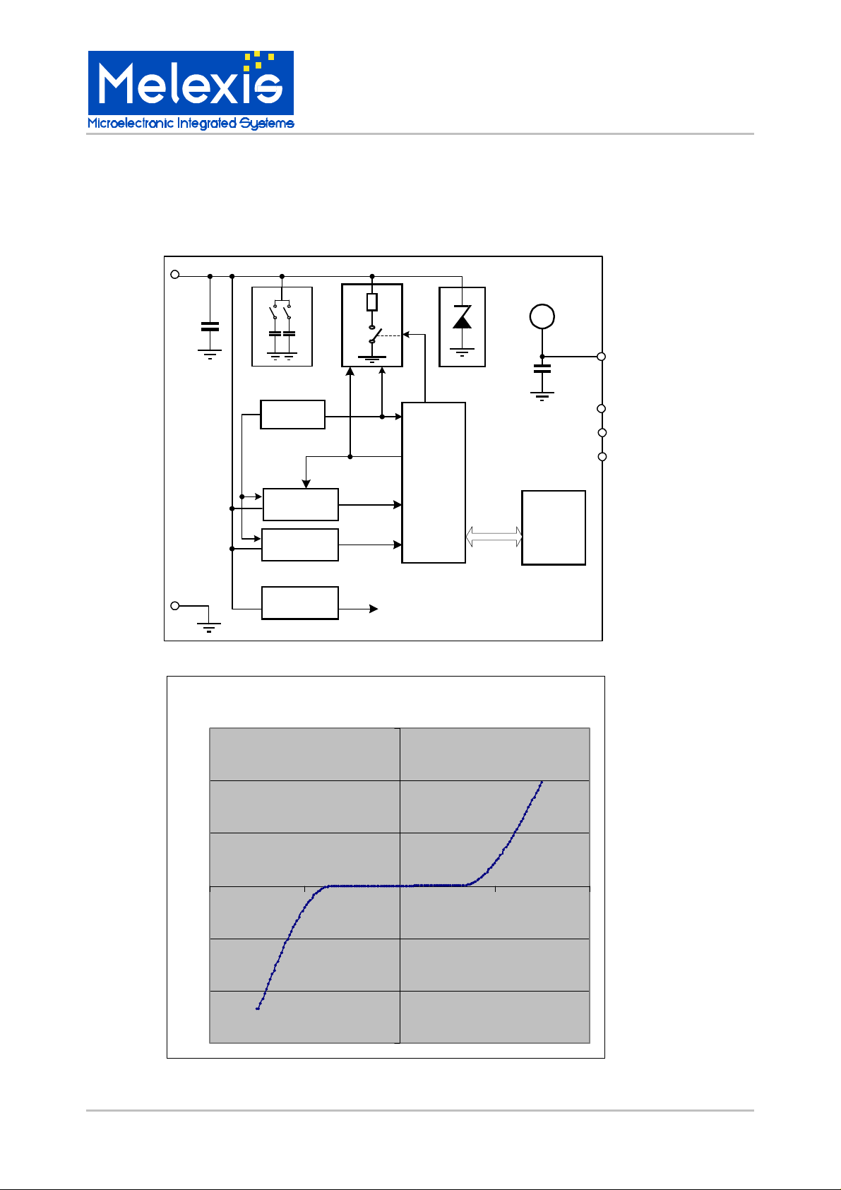
Block diagram
COIL
MLX90111
128bit Read Write Transponder
VSS
Ctune
[mA]
15
Trimming
POR
CLOCK
RECOVERY
DEMODUL.
SUPPLY
Modulator
SPEED
CLOCK
DATA
VDD
M
O
D
Digital
Controller
RF Limiter
Cbuffer
ADDR
DATA
MLX90111 clamping (DC)
VDD
VDD
TCKIN
TEST
DATAIO
EEPROM
10
5
0
[V]
-20 -10 0 10 20
-5
-10
-15
MLX90111 128bit Read Write Transponder Page 3 of 12 Rev 1.12 5-Feb-01
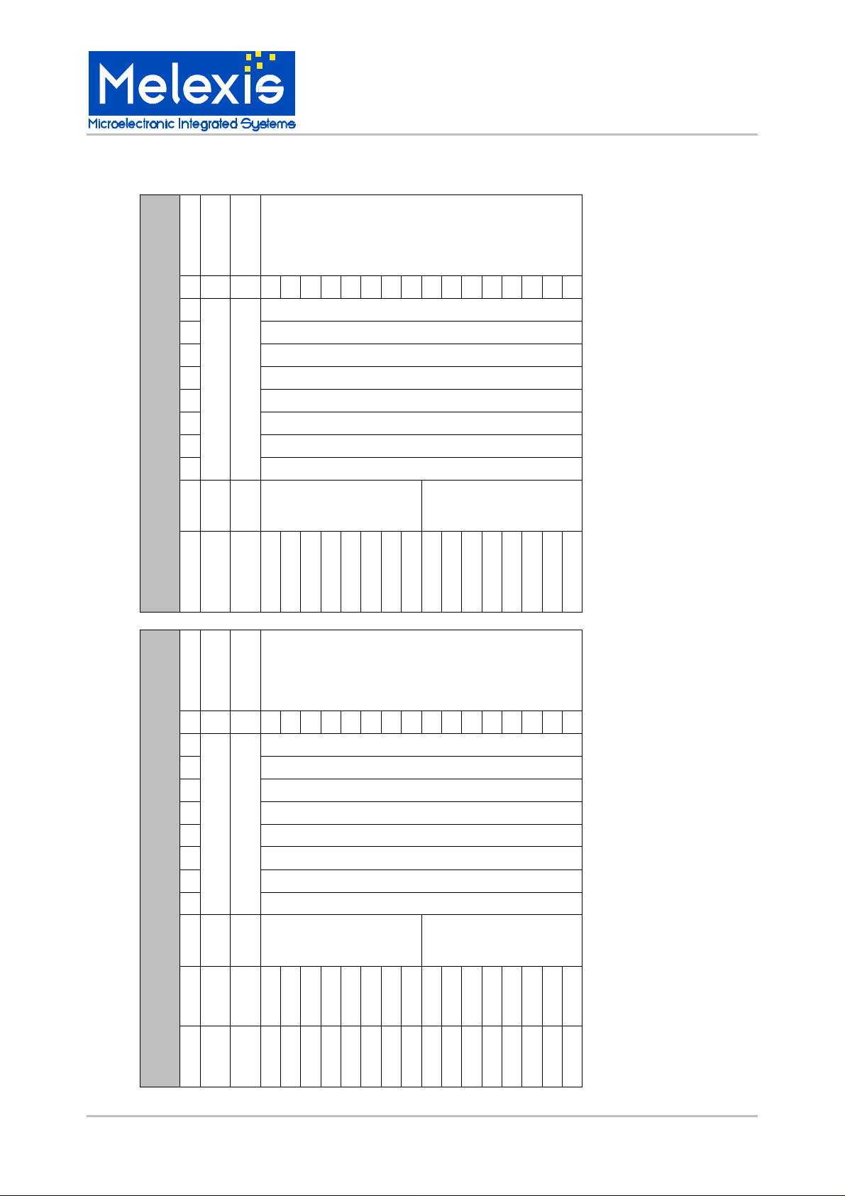
EEPROM memory maps
ADDRESS
FUNCTION
COMMAND
F E D C B A 9 8 7 6 5 4 3 2 1 0
0
1
2
3
ID
4
5
6
7
Read memory map
CONTINUOUS
MLX90111
128bit Read Write Transponder
BITPOSITION (MSB first)
B
WPW
C
Tune+CFG
ADDRESS
FUNCTION
0
1
2
3
ID
4
5
6
7
Lock word: "01010101" WPW(FLAGS)
CMF1
0
CMF1
COMMAND
CMF1
T4T3T2T1T0
F E D C B A 9 8 7 6 5 4 3 2 1 0
Write memory map
8
WPW
Lock word: "01010101" WPW(FLAGS)
CMF2
0
0
0
0
0
BITPOSITION (MSB first)
0
0
0
CODE
SPEED
9
Tune
A
CFG
MLX90111 128bit Read Write Transponder Page 4 of 12 Rev 1.12 5-Feb-01
CMF2
CMF2
0
T4T3T2T1T0
0
0
0
0
0
0
0
0
0
0
0
0
0
0
0
0
0
0
0
0
0
0
0
0
CODE
SPEED
 Loading...