

MELEXIS MLX90110 Datasheet
MLX90110
128bit OTP/RW Transponder
Features
- 144bit EEPROM code
- Very small size 125kHz Read/Write Transponder
- Very Big reading range, and large write range.
- EEPROM programmable Configuration word for different encoding and data rate options
- 80pF integrated tuning capacitance
- 100,000 write cycle, 10 year EEPROM retention
- Single command programming with integrity check.
- Dimensioned for ISO-chipcard, without need for tag module.
- Conceived for use and without Goldbumps
Applications
Animal ID (ISO 11784/-85 compliant), Access Control, Juke box logistics control, Material
Logistics, Production Flow Control.
Ordering Information
Part No. Temperature Ranges Delivery form
MLX90110 25 °C Consumer Sawed wafer on frame
-40 to 85 °C Automotive Bare die in blistertape
SOIC-8 150mils
Production parts available Q2 2001
Functional Diagram Description
The MLX90110 is a 128bit Read Write and OTP
transponder operating at 125kHz. It has been
designed as a low cost read write solution for
applications which don't require high flexibility in
terms of write range, like in production
environments.
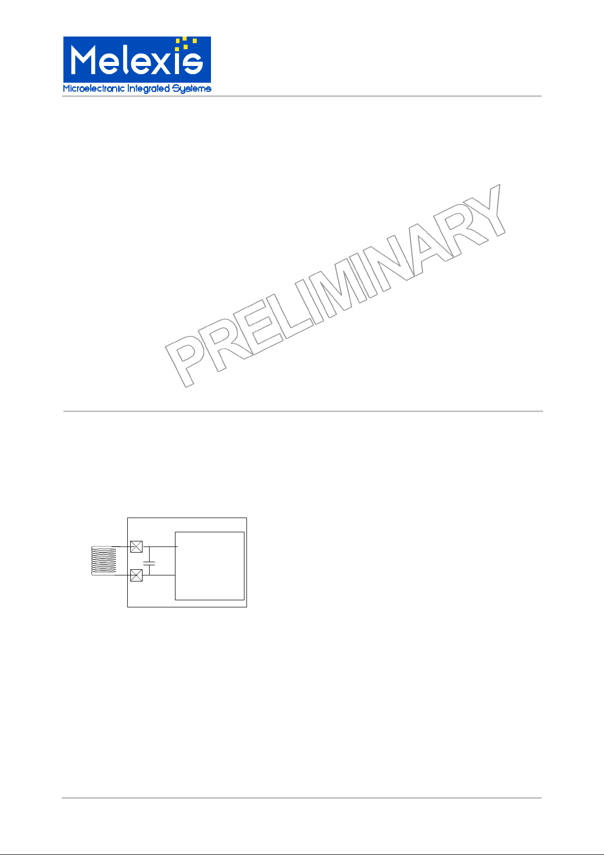
MLX90110
Coil
L
GND
C
tune
Clock and power supply are taken from the
electromagnetic field. A resistor is switched in
parallel to the resonant circuit formed by the
integrated tuning capacitor (80pF) and the
external coil to amplitude modulate the
electromagnetic field. No external components
are needed except for the antenna coil.
The EEPROM is configured as 9 words of 16
bits. Words 1 to 8 form the ID and are
continuously read out during normal operation.
The transponder can be configured for
Manchester or Biphase encoding, at 2 or 4
kBaud by programming the corresponding bits in
the 9th EEPROM word.
By setting 2 other bits in the 9th word, the
transponder memory can be partially or
completely locked. In the latter case it becomes
a Read Only transponder. In the first mode
words 5, 6, 7, 8 and 9 can be rewritten with
password access.
MLX90110 128bit MTP Transponder Page 1 of 10 Rev 1.14 1-Dec-2000
MLX90110
128bit OTP/RW Transponder
MLX90110 Electrical Specifications
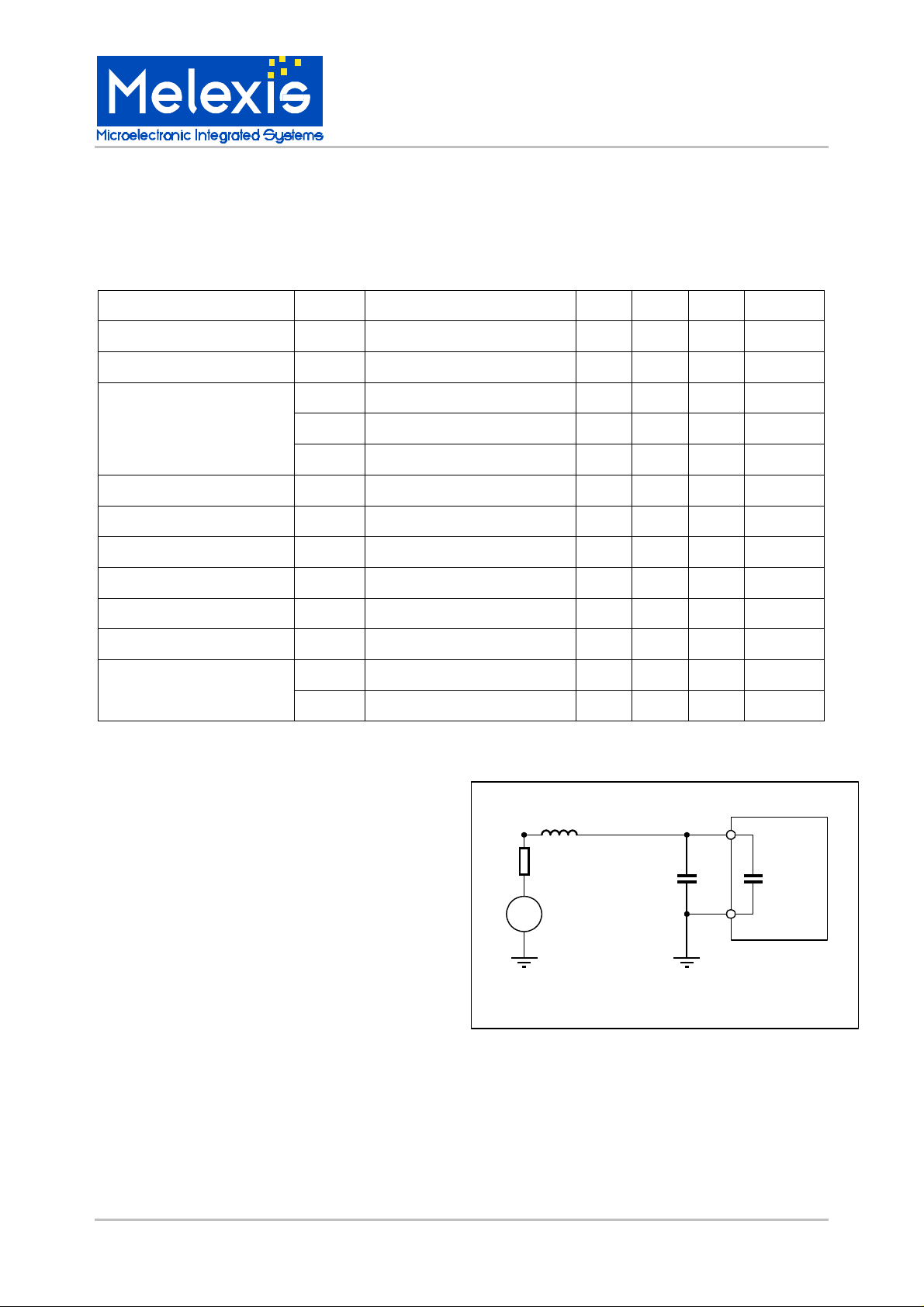
Operating Parameters are based on test set up (see Schematic below).
Toper = -40°C to 85°C, Operating frequency = 120kHz (unless otherwise specified)
Parameter Symbol Test Conditions Min Typ Max Units
Regulated supply voltage VDD (3) 3.0 4.0 V
Power On Level VPOR Continuous normal reading of the ID 1.55 1.8 2.2 V
Sensitivity level Vacsens Continuous normal reading of the ID 200 170 mV (4)
Transponder Modulation Depth
Weak power: Vacmin = 200mVpp 0.3 4 V
Medium power: Vac = 5Vpp 2.8 7.5 V
High power: Vac = 20Vpp 5 10 V
High Programmation voltage Vacprh 5 V (4)
Low Programmation voltage Vacprl 2.5 V (4)
EEPROM writing supply current Iee 10
µA
EEPROM data retention Tret Critical reading ID 10 year
EEPROM write cycles Ncycle Critical reading ID 100k cycles
Coil-GND tune capacitor Toper=25oC 77 80 83 pF
IclampLow VdutDC = +/- 2V 40 1000 nADC input current clamping
IclampHigh VdutDC = +/- 10V 1 3.5 10 mA
Notes:
Note (1): All specification values are characterized
and tested 100%, or guaranteed by design.
Note (2): All specifications are valid for Manchester
and Biphase encoding, and for 2kbaud and 4kbaud
data rate options.
Vin
50
L=6.8mH
Cpar=10pF
Qrc @ 120KHz=48.8
C1+C2=250pF
Vdut
C1 C2
COIL
90110
DUT
Note (3): Maximum supply voltage is generated by
forcing 10mA between coil and ground pin.
Vac
GND
Note (4): For the test setup, AC generator voltages
are equivalent to following voltages on the coil: see
graph (to be added).
MLX90110 128bit MTP Transponder Page 2 of 10 Rev 1.14 1-Dec-2000
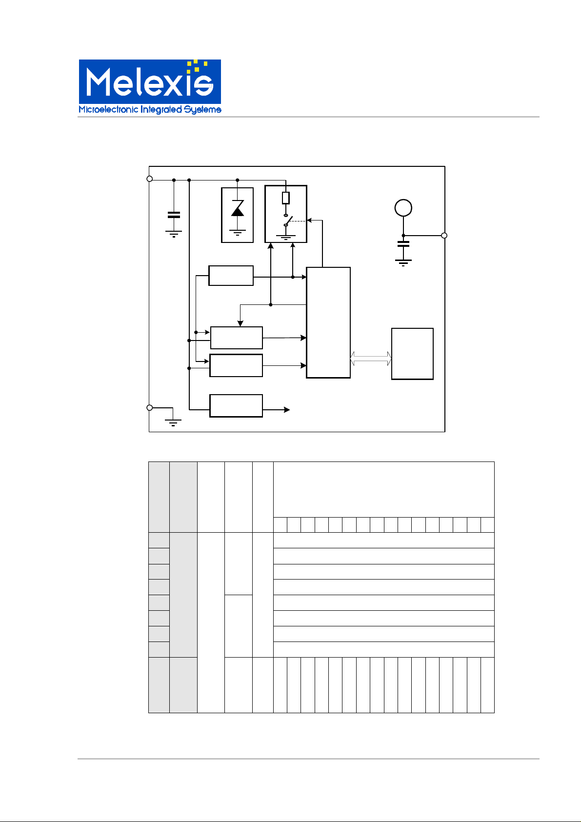
Block diagram
COIL
MLX90110
128bit OTP/RW Transponder
Ctune
VSS
EEPROM memory map
RF Limiter
POR
CLOCK
RECOVERY
DEMODUL.
SUPPLY
Modulator
SPEED
CLOCK
DATA
VDD
M
O
D
Digital
Controller
Cbuffer
ADDR
DATA
VDD
VDD
EEPRO
M
BITPOSITION (MSB first)
ADDRESS
FUNCTION
WP = RW = 0
WP = 1
WP = 0, RW= 1
F E D C B A 9 8 7 6 5 4 3 2 1 0
0
1
2
RO
3
4
5
6
ID
RW
RO
RW
7
-
X
X
X
X
X
X
X
X
X
X
X
8
Options
(RW)
X
WP
RW
CODE
SPEED
MLX90110 128bit MTP Transponder Page 3 of 10 Rev 1.14 1-Dec-2000
 Loading...