

MELEXIS MLX10407 Datasheet

MLX10407
5-Channel Gauge Driver with Serial Link
Features and Benefits
Supply voltage up to 12 V
Interface directly with 5 V CMOS logic MCUs
Serial link
Can drive two 360° actuators & three 90° actuators simultaneously
Open circuit / short -circuit detection of the drivers outputs
Small size (SO24 package)
Real Time Angle Tracking
Applications
Logometer Driver Dashboard
Industrial Metering
Ordering Information
Part No. Temperature Suffix Package Temperature Range
MLX11407CA N/A SO24 -40C to +85C Automotive
Functional Diagram
Description
The 10407 is a MCU peripheral for logometers control using SIN/COS PWM commands. The circuit controls two
independent sets of CMOS power bridges. A ten-bit angle is displayed with a 9 bit per quadrant resolution PWM whose
frequency is set by a crystal oscillator. A power-on self test detects open or short-circuit outputs for each logometer and
a real time angle tracking avoids display errors.
The 10407 can also drive three small angle logometers (90°). A three wire serial link allows bidirectional communication
with the MCU.
MLX902xx Name of Sensor Rev Y.X 22/Aug/98 Page 1
MLX10407 5-Channel Gauge Driver with Serial Link Page 1 Rev 1.1 28/Apr/01
MLX10407
5-Channel Gauge Driver with Serial Link
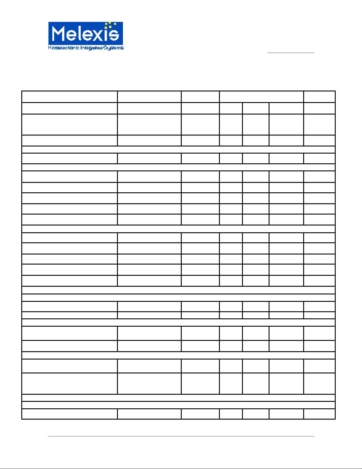
DC Electrical Characteristics
Tamb = -40 to 85°C, VDD = 4.5 V to 12 V unless otherwise specified.
Characteristics Test Conditions
Supply current Inputs at VDD or
VSS, No loads on
outputs
Maximum power dissipation
Inputs
Input capacitance
Pin 11
Pull-down resistance
Input voltage LOW
Input voltage HIGH
Hysteresis VDD = 8.5 V
Leakage current pin at VDD or VSS
Pin 12, 13, 14, 15, 17
Input voltage LOW
Input voltage HIGH
Hysteresis VDD = 8.5 V
Leakage current (pin 12, 15, 17) pin at VDD or VSS
Pull-down resistance (pin 14) Rpd 0.8 1.5 kOhm
Symbol Limits Unit
Min Typ Max
ICC
PDmax
Cin
Rpd 125
VIL -0.3
VIH 4
VHYS 0.5
IL -1
VIL -0.3
VIH 4
VHYS 0.5
IL -1
5.5 mA
620 mW
10 pF
750 kOhm
1 V
VDD+0.3 V
2.5 V
1 µA
1 V
VDD+0.3 V
2.5 V
1 µA
Outputs
Pin 16
Low level output voltage IOUT < 500 µA
High level output leakage current VOUT=VDD ILKG 10 µA
Pin 2, 3, 5, 6, 20, 21, 23, 24
Drop-out voltage for each pair of
buffers
Mismatch of drop -out voltage
Pin 7, 8, 9
Output voltage low VDD = 8.5V, Tamb=
Output voltage high VDD = 8.5V, Tamb=
Oscillator
Pin 18,19
Input pin capacitance
MLX10407 5-Channel Gauge Driver with Serial Link Page 2 Rev 1.1 27/Apr/01
VDD = 8.5V, Tamb =
25°C, Icoil = 30 mA
25°C, Isink = 40mA
25°C, Isource =
40mA
VOL
Vd
D Vd
VOL
VOH 6.8 7.8
Cin
0.3 V
1.6 V
± 50 mV
0.3 0.6 V
10 20 pF
V
5-Channel Gauge Driver with Serial Link
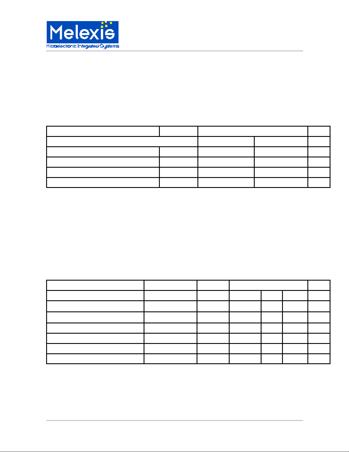
ABSOLUTE MAXIMUM RATINGS
MLX10407
Parameter Symbol
Min Max
Storage Temperature Range Tstg -40 +150 °C
Operating Temperature Range Tamb -40 +85 °C
Supply Voltage Range VDD -0.3 14.0 V
Input Voltage Range Vi -0.3 VDD +0.3 V
Value
AC Electrical Characteristics
Tamb = -40 to 85°C, VDD = 4.5 V to 12 V unless otherwise specified.
Characteristics Test Conditions
Symbol
Limits
Unit
Unit
Min Typ Max
Oscillator 0.95 8.4 MHz
Clock frequency Fclk 8 MHz
Serial communication
Serial data clock frequency Fsclk 500 kHz
Time for DIN stable to SCLK rise 100 ns
Hold time for DIN 100 ns
MLX902xx Name of Sensor Rev Y.X 22/Aug/98 Page 3
MLX10407 5-Channel Gauge Driver with Serial Link Page 3 Rev 1.1 28/Apr/01
 Loading...