

Page 1
查询MLX10402供应商
MLX10402
Motor Driver IC
Features and Benefits
• Small package (SOIC16)
• Current limitation
• Low power consumption
• Thermal Overload protection
• Microcontroller compatible
Applications
• Small DC inductive motor driver
• Lamp driver
Ordering Information
Part No. Temperature Suffix Package Temperature Range
MLX10402 C DF (SOIC 16) ± 0°C to 70°C
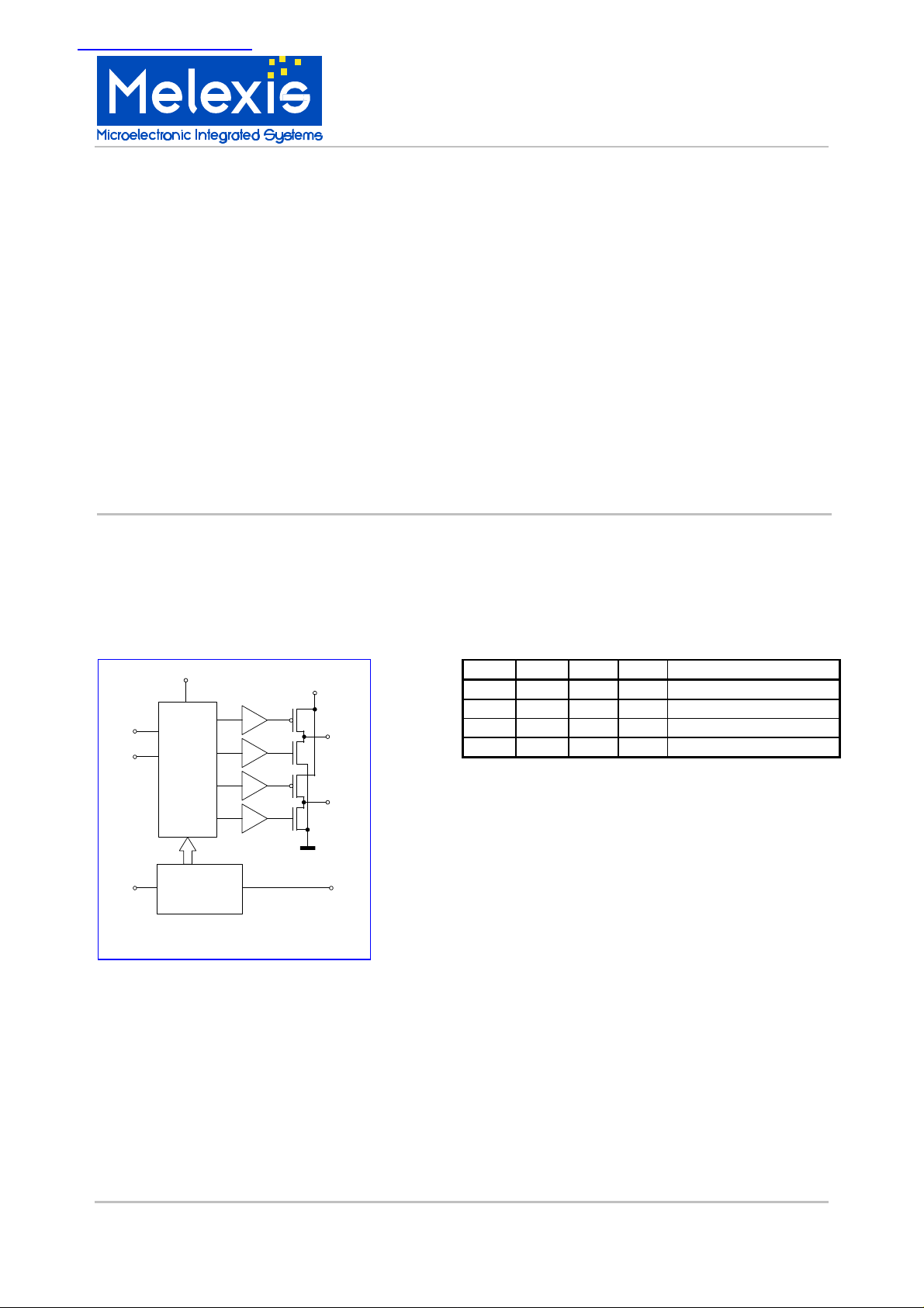
Functional Diagram
VDD
IN1
IN2
AUTO
CONTROL
CIRCUIT
TEMPERATURE
PROTECTION
10402 Motor Driver IC
VCC
OVERTEMP
Description
The IC drives directly small DC inductive or active
loads like electric motors, lamps, etc. There are four
main driving modes. These are set by digital inputs
“In1” and “In2” :
IN1 IN2 M1 M2 Driving Mode
1 0 1 0 Forward
0 1 0 1 Reverse
M1
M2
1 1 0 0 Brake (Motor shorted)
0 0 Z Z Off (Motor disabled)
The current of the output-drivers is limited for all
kinds of overload- and short-circuit conditions and in
the whole supply voltage- and temperature range.
The outputs “M1” and “M2” need to be off-chip
protected with against motor inductances by
standard Si-diodes.
If the temperature of the chip exceeds a certain
value (changable with pin “Auto”), the temperatureoverload protection-circuit disables the outputs,
preventing the chip from being overheated. In
addition, this so called “temp ovl”-state is signaled
with a low level at the “overtemp”-pin.
MLX10402 Page 1 12/Oct/01
3901010402 Rev. 002
Page 2
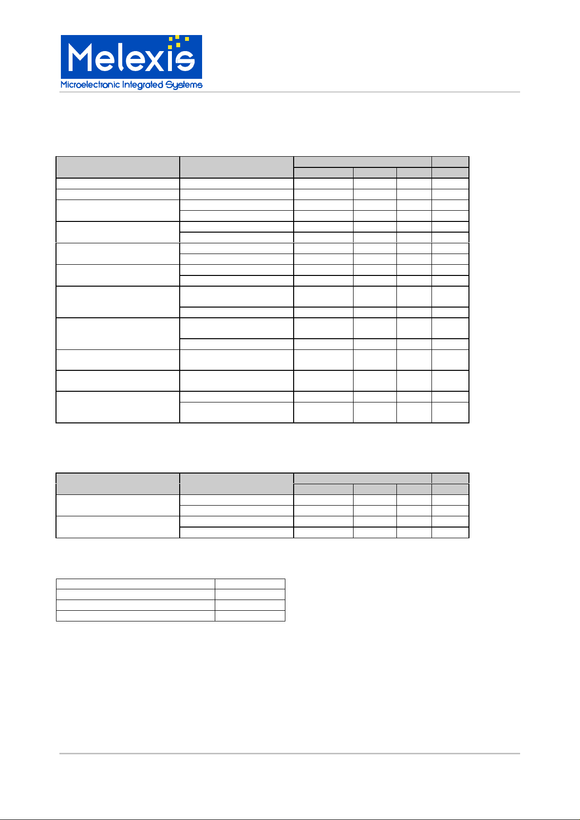
Electrical Characteristics
Following characteristics are valid at ± 0°C to 70°C
Characteristics Test Conditions Limits
Min Typ Max Units
Supply voltage Vcc
Supply voltage Vdd
Mean motor current
Motor current limit
Brake current
Voltage drop at the 2
output transistors together
Supply current Icc
Supply current Idd
Inputs “In1” & “In2”
Input “Auto”
(Pull up)
Output “overtemp”
(Open DRAIN)
Vcc=9V 330 mA
Vcc=6V 300 mA
Vcc=9V 550 mA
Vcc=6V 500 mA
Vcc=9V 240 mA
Vcc=6V 180 mA
Vcc=9V, Icc=300mA 1.2 V
Vcc=6V, Icc=260mA 1.2 V
FORW, REVERSE,
BRAKE, TEMP OVL
OFF mode 10.0 µA
FORW, REVERSE,
BRAKE, TEMP OVL
OFF mode 10.0 µA
Logic level TTL,
Current sourced
(if tied to GND)
TEMP OK output HiZ
TEMP OVL output
@1mA sink
4.5 5.0 5.5 V
MLX10402
Motor Driver IC
5 9 12 V
5.0 mA
1.0 mA
1.4 V
25 uA
0.4 V
Temperature characteristics
Characteristics Conditions Limits
Min Typ Max Units
TEMP OVL-Protection “Auto” = 1 or floating
turn on Temperature “Auto” = 0
TEMP OVL-Protection “Auto” = 1 or floating
turn off Temperature “Auto” = 0
Absolute Maximum Ratings
Vcc +16V
Maximum Output Current 700mA
Die Temperature +160°C
Storage Temperature -55°C to 125°C
122 °C
155 °C
93 °C
105 °C
MLX10402 Page 2 12/Oct/01
3901010402 Rev. 002
Page 3

Pin-out
Pin 1: M2 Pin 16: AUTO
Pin 2: VCC Pin 15: N.C.
Pin 3: N.C. Pin 14: GND (logic)
Pin 4: GND Pin 13: OVERTEMP
Pin 5: GND Pin 12: VDD
Pin 6: N.C. Pin 11: N.C.
Pin 7: VCC Pin 10: IN1
Pin 8: M1 Pin 9: IN2
Note: N.C. = must be "not connected".
Typical application circuit
VDD
MLX10402
Motor Driver IC
VCC
OVERTEMP
CONTROLLER
IN1
IN2
AUTO
CONTROL
PROTECTION
pu
CIRCUIT
&
Logic GND GND
Revision Table
No Changes
1.0
002
Conversion to Melexis lay-out standards
For the latest version of this document, go to our website at:
www.melexis.com
M1
MOTOR
M2
Or for additional information contact Melexis Direct:
Europe and Japan: All other locations:
Phone: +32 13 61 16 31 Phone: +1 603 223 2362
E-mail: sales_europe@melexis.com E-mail: sales_usa@melexis.com
QS9000, VDA6.1 and ISO14001 Certified
MLX10402 Page 3 12/Oct/01
3901010402 Rev. 002
 Loading...