

Page 1

USER MANUAL
MLX90614 Evaluation board
390129061401 Page 1 of 20 User Manual
Rev 001 Oct/2006
MLX90614 Single and Dual zone Infra Red
thermometer Evaluation Board
EVB90614
User Manual
Page 2

USER MANUAL
MLX90614 Evaluation board
390129061401 Page 2 of 20 User Manual
Rev 001 Oct/2006
Table of Contents
1 Introduction ..................................................................................................................... 3
2 Host computer requirements ......................................................................................... 3
3 Installing the software .................................................................................................... 3
4 Getting started with MLX90614 evaluation board ........................................................ 4
4.1 MLX90614 evaluation board overview .................................................................................................................................................4
4.2 Connecting the EVB90614 evaluation board.......................................................................................................................................5
5 Getting started with MLX90614 Configurator ............................................................... 5
5.1 MLX90614 Configurator overview ........................................................................................................................................................5
5.2 Working with MLX90614 Configurator..................................................................................................................................................5
5.3 Configuration of MLX90614 modules ...................................................................................................................................................8
5.4 Manual sending commands................................................................................................................................................................11
5.5 Demonstration of SMBus and PWM temperature measuring ...........................................................................................................12
5.6 Quick customization of MLX90614 thermometers .............................................................................................................................14
5.7 Updating EVB90614 firmware ............................................................................................................................................................16
6 Troubleshooting............................................................................................................ 17
7 Disclaimer...................................................................................................................... 18
APPENDIX A – EVB90614 commands set ......................................................................19
APPENDIX B – EVB90614 schematics............................................................................ 20
Page 3

USER MANUAL
MLX90614 Evaluation board
390129061401 Page 3 of 20 User Manual
Rev 001 Oct/2006
1
Introduction
The EVB90614 is designed to support MLX90614 infrared thermometer modules.
The communication between PC and the evaluation board is accomplished by USB.
The Demonstration Kit contains the following items:
1. FS USB demonstration board, pre-programmed with USB
bootloader and demonstration firmware.
2. A standard USB cable for use in communicating with the board.
3. 2 pcs. MLX90614AAA (single zone 5V)
4. 2 pcs. MLX90614BAA (single zone 3V)
5. CD-ROM, containing the USB HID driver and EVB90614 software
The EVB90614 is designed to allow OEMs to configure the MLX 90614 IR thermometer
for virtually any application quickly. OEMs can quickly experiment with temperature
ranges, optics, etc. to find the best IR configuration to meet the application needs. Once
the best configuration is established, low volume OEMs can easily configure IR modules
for their own use. For high volume OEMs, Melexis can supply special configured
modules, ready to install into the customer’s application. Please contact IR Sales at
Melexis for quotations.
The EVB90614 allows engineers to customize the MLX90614 for high accuracy IR
measurements in an R&D or Laboratory setting.
2
Host computer requirements
To communicate with and program the EVB90614 evaluation board, the following
hardware and software requirements must be met:
• PC-compatible system
• An available USB port
• CD-ROM drive (for use with the accompanying CD)
• Microsoft Windows 98, Second Edition (98SE), Windows 2000 Desktop or Windows XP
Note1: EVB90614 is HID USB device and will require no drivers on PCs that support HID class USB
devices (except Microsoft Windows 98, Second Edition (98SE)).
Check www.melexis.com for most recent release of the software.
3
Installing the software
As an USB device, the demonstration board requires very little effort to install.
Most of the work is done by the operating system. The software is installed simply by
running the file “setup.exe”.
The software will be installed in a separate Melexis directory and can be accessed from
Start/Programs/Melexis/ Mlx90614 Configurator.
Note2: If your version of Windows does not support the HID USB devices you might need to install USB
driver (check
www.melexis.com
for such driver).
Page 4
USER MANUAL
MLX90614 Evaluation board
390129061401 Page 4 of 20 User Manual
Rev 001 Oct/2006
4
Getting started with MLX90614 evaluation board
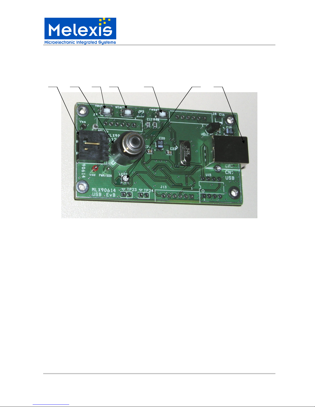
4.1 MLX90614 evaluation board overview
1 2 3 4 5 6 7
Fig.4.1
Top view of evaluation board is shown on Fig.4.1.The main elements include:
1. Extension connector (70553-0003 from www.molex.com) allowing additional
MLX90614 modules to be connected to SMBus.
Connector pin description:
pin1 - SCL/Vz (pin 1 is marked on the plastic body of the connector)
pin2 - PWM/SDA
pin3 - Vdd
pin4 - Vss
2. ZIF socket for MLX90614
3. Button “next”
4. Button “start”
5. Button “reset”
6. RGB status LED
7. USB "B" Receptacles
The EVB90614 board receives its power supply only from the USB cable (Bus-Powered
Device). External power supply source is not needed.
Page 5
USER MANUAL
MLX90614 Evaluation board
390129061401 Page 5 of 20 User Manual
Rev 001 Oct/2006
4.2 Connecting the EVB90614 evaluation board
To connect the evaluation board:
1. Unbox and unwrap the board, and set it on a non-conductive surface near the
host system.
2. Connect the USB cable (supplied in the kit) to an open USB port on the host
system or a USB hub connected to the host system, and to the USB connector on the
board. The LED will shine in BLUE.
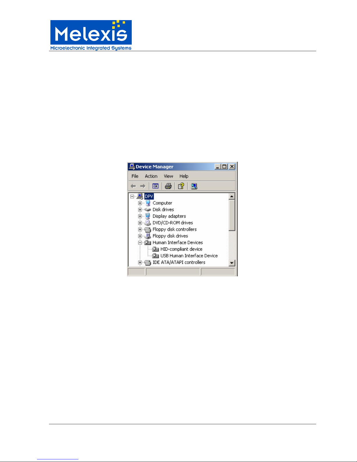
3. EVB90614 evaluation board is HID compliant device so a special USB device
driver is not needed (except when using Window 98 & 98SE).
4. Check the board connection. This can be done from Start/Settings/Control Panel/
System/Hardware/Device Manager (Fig.4.2).
Fig.4.2
5
Getting started with MLX90614 Configurator
5.1 MLX90614 Configurator overview
The MLX90614 Configurator is a Windows-based software application designed to
be used with the EVB90614 evaluation board for evaluating Melexis MLX90614 infrared
thermometers. Using this software, features and performance of MLX90614 infrared
thermometers can be evaluated. All basic configurations of MLX90614 are also supported
in user-friendly format. Configuration is written in EEPROM of each MLX90614 and will be
the POR default afterwards. This way the MLX90614 can be further used without EVB in
target applications.
5.2 Working with MLX90614 Configurator
Insert a MLX90614 thermometer in the ZIF socket (see Fig.4.1). Make sure that
module benchmark coincides with the mark on the PCB.
The software can be launched from Start/Programs/Melexis/ MLX90614 Configurator.
Page 6
USER MANUAL
MLX90614 Evaluation board
390129061401 Page 6 of 20 User Manual
Rev 001 Oct/2006
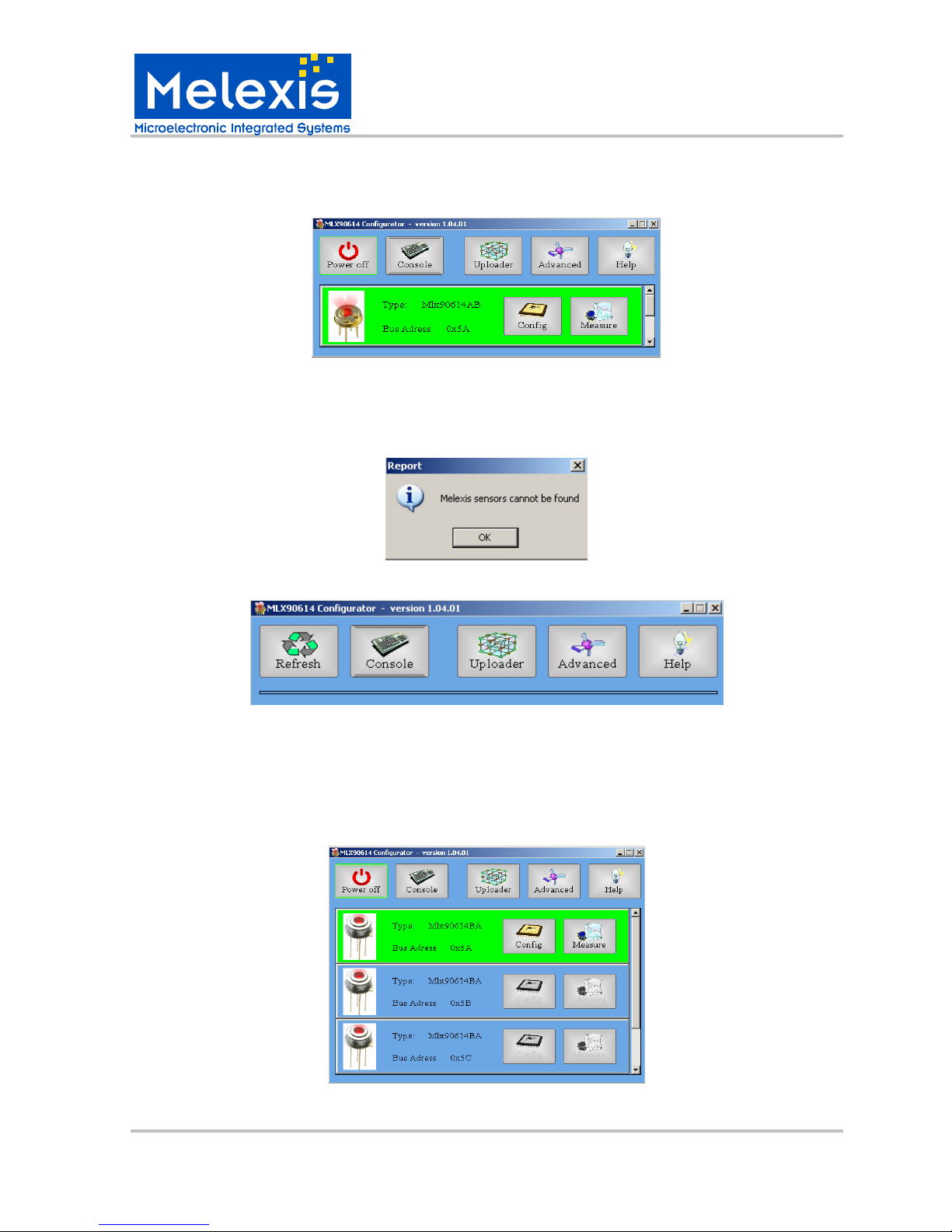
The Configurator automatically recognizes the module type, address and voltage supply
(Fig.5.1). The status LED is shinning GREEN.
Fig.5.1
If there is no thermometer module inserted on the EVB or the module is not a MLX90614,
the user will be notified (Fig.5.2). Click the button OK. The main panel looks as shown in
Fig.5.3.
Fig.5.2
Fig.5.3
Note that the buttons Power off and Refresh are alternating.
The MLX90614 Configurator gives the opportunity to connect a few MLX90614 modules in
a network (Fig.5.4). Note that if in a network both 3V (MLX90614Bxx) and 5V
(MLX90614Axx) modules are present, currently only the 3V modules will be available.
Fig.5.4
Page 7

USER MANUAL
MLX90614 Evaluation board
390129061401 Page 7 of 20 User Manual
Rev 001 Oct/2006
Note3: If in a SMBus network there is a module with address zero it will be not reported. A module with
SMBus address zero will be reported if it is the only one connected to board. Also modules with the same
SMBus addresses connected to the network will cause conflict on the bus when operation reading is done.
Note4: It is strongly recommended to save factory default EEPROM of every new MLX90614 before
doing anything else with it (See below how to do that).
Note5: schematics for PCBs to attach multiple modules using connector 1 can be found on page 20.
Main panel description
Turn off module power supply.
Opens “Console Utility” window for manual sending of commands.
See Appendix A for commands set.
Opens “Configuration uploader” window for quick replication of
MLX90614 infrared modules’ configuration.
Opens “Advanced” window from which user can upgrade EVB firmware,
change measuring unit of the temperature scale and relocate the log file.
Opens current EVB90614 User Manual. It is recommended to check
www.melexis.com for updates and related documents.
Opens “Configuration utility” window used for configuring MLX90614
infrared thermometers.
Opens “Measure utility” window for temperature measurements.
Dual zone module identification picture.
Single zone module identification picture.
(Re-)start system to refresh information about the modules.
Page 8

USER MANUAL
MLX90614 Evaluation board
390129061401 Page 8 of 20 User Manual
Rev 001 Oct/2006
5.3 Configuration of MLX90614 modules
From the main panel push the button Config. ”Configuration utility” window is
opened (Fig.5.5).
Fig.5.5 Fig.5.6
From this window the user can configure the MLX90614 module. A short description
of every setting field follows bellow. For a detailed description of the settings please refer to
the MLX90614 datasheet. These settings are stored in MLX90614 EEPROM and will be
the power-up default configuration.
To max, To min - defines the temperature ranges for object temperature in PWM mode.
Ta max, Ta min - defines temperature ranges for ambient temperature in PWM mode.
PWM/SMBus/Relay - chooses between SMBus, PWM and Thermo Relay mode.
PWM mode - defines single or extended PWM mode
PWM struct - selects what data will be transmitted via the PWM.
PWM period - defines the PWM period. A list of available settings as drop-down menu.
PWM period repetitions - defines how many times each PWM period will be repeated.
Any even number of repetitions from 0 to 62 is valid.
PWM pin configuration - chooses between NMOS “open drain” and “push pull” PWM
output.
Sensor zone - defines the number IR sensors. This number is factory programmed and is
recommended not to be altered.
SMBus address - set SMBus slave address. All values between 0 and 127 are valid. All
MLX90614 will accept communication with slave address 0. Therefore in SMBus network a
slave address 0 will be useless.
F.I.R filter- drop-down list of settling time available via embedded in MLX90614 digital
filter. Slower settling comes with less noise.
Module type and SMBus slave address identification fields.
Page 9

USER MANUAL
MLX90614 Evaluation board
390129061401 Page 9 of 20 User Manual
Rev 001 Oct/2006
I.I.R filter [%] – drop-down list of available values for impulse limit. 100% passes all
impulse, 50% cuts impulse magnitude in half via embedded in MLX90614 IIR filter. Note
that the settling time depends on both FIR and IIR filters settings.
Some options are available from the drop-down menu while other must be typed by the
user. For example to change the object temperature range double click on To min or To
max field and type the new range.
To change between PWM and SMBus mode double click on PWM/SMBus/Relay field and
select from the drop-down menu the desired option (Fig.5.7).
Fig.5.7
Note that when the Thermo relay option is selected the fields To max and To min change
in Hysteresis and Threshold respectively (Fig.5.6). Hysteresis adds to threshold on each
side. Trip points will be Threshold+Hysteresis for rising temperature and
Threshold+Hysteresis for decreasing temperature.
Tick to view the full EEPROM memory in hexadecimal view (Fig.5.8).
Note that only highlighted cells are accessible by the user (see MLX90614 datasheet for
more information). All other EEPROM cells contain factory calibration values and are
protected against erase and writes.
Fig.5.8
Note 6: Do not write SMBus address 0x00 in any module when you make a sensor network because reading
this module will cause all devices on the network to reply. This will result in confusion on the SMBus.
Page 10

USER MANUAL
MLX90614 Evaluation board
390129061401 Page 10 of 20 User Manual
Rev 001 Oct/2006
Click button Read to read the complete EEPROM memory. Starting the SW or clicking
“Refresh” after “Power Off” will automatically read the EEPROM, too.
Click button Write to write changed EEPROM cells. Factory calibration values will not be
altered. Writing EEPROM cell is automatically preceded by erasure.
Click button Save file to save EEPROM in a bin file. Refer to Fig.5.9.
Click button Load file to load a bin file. If the loaded bin file is to be written into MLX90614
EEPROM a “Write” must be clicked afterwards. Refer to Fig.5.10.
Fig.5.9
Fig.5.10
Page 11

USER MANUAL
MLX90614 Evaluation board
390129061401 Page 11 of 20 User Manual
Rev 001 Oct/2006
5.4 Manual sending commands
From the main panel push the button Console. ”Console utility” window is opened
(Fig.5.11).
Fig.5.11
Type a valid command in the Command field, push Execute (or button ‘Enter’ on the
keyboard). The result will be reflected in the Information field. The supported commands
are described in APPENDIX A. The console utility is provided for extended functionality. All
read/configure/write as well as measure/log data operations can be done without this utility.
Command field
Information field
Page 12

USER MANUAL
MLX90614 Evaluation board
390129061401 Page 12 of 20 User Manual
Rev 001 Oct/2006
5.5 Demonstration of SMBus and PWM temperature measuring
From the main panel push the button Measure. The ”Measure utility” window is
opened (Fig.5.12).
Fig.5.12
Note7: If the used module is single zone only two thermometers will be present on the screen (Fig.5.13).
Fig.5.13
Push the button Start to start temperature measurement. With the MLX90614 configured in
PWM mode the PWM output depends on the ranges written in EEPROM. These ranges
Page 13

USER MANUAL
MLX90614 Evaluation board
390129061401 Page 13 of 20 User Manual
Rev 001 Oct/2006
are automatically read and filled in the Min/Max boxes on this screen. An example is
shown on Fig.5.14.
If the module is configured in SMBus mode no information is displayed in the lower right
corner.
Fig.5.14
In the field “Measure period” the user can make the measuring faster or slower.
Max and Min fields permit user to change graphic scales.
When the measurement is started data will be acquired in a log.csv file. If the SMBus mode
is selected the following RAM registers will be logged in the log.csv file (See MLX90614
datasheet for more information):
Ambient sensor data - SMBus RAM address=0x03h
IR sensor 1 data - SMBus RAM address= 0x04h
IR sensor 2 data - SMBus RAM address= 0x05h
Linearized ambient temperature Ta - SMBus RAM address =0x06h
Linearized object temperature (IR1) T
OBJ1
- SMBus RAM address= 0x07h
Linearized object temperature (IR2) T
OBJ2 -
SMBus RAM address = 0x08h
If PWM mode is selected logged data will depend on the chosen PWM structure.
Every time a measurement is started the log file is continued, with the entire EEPROM
saved as new heading row.
Note8: In Regional and Language Options (available from Start/Settings/Control panel) list separator need
to be “,” and decimal symbol – “.” in order to get the CSV log file opened in an easy to use form in EXCEL.
Note9: Note that the CSV log file is the same for all measurements, there is not a separate file for every
module that is measured.
Page 14

USER MANUAL
MLX90614 Evaluation board
390129061401 Page 14 of 20 User Manual
Rev 001 Oct/2006
To change the temperature measuring unit (C, F or K) and to relocate the log.csv file:
1. Click the button Advanced from main panel
2. Click the button Option available in “Advanced” window.
3. From “Software settings” window choose the desired settings (Fig.5.15).
Fig.5.15
5.6 Quick customization of MLX90614 thermometers
Push the button Uploader on the main panel. The “Configuration uploader” window
is opened (Fig.5.16).
This window is very similar to “Configuration utility” window but here the user cannot
change the EEPROM.
Click the button “Select EEPROM” to open the window “Open EEPROM file” (See
Fig.5.10). Browse to select the desired EEPROM configuration file and click the button
“Open”. The chosen EEPROM configuration is loaded (Fig.5.17). Tick
to view the full EEPROM memory in hexadecimal view if desired.
Fig.5.16 Fig.5.17
Page 15

USER MANUAL
MLX90614 Evaluation board
390129061401 Page 15 of 20 User Manual
Rev 001 Oct/2006
The user has two choices to load an EEPROM configuration in a MLX90614 module:
Upload
Quick upload
When the Upload button is pushed the software automatically checks the module
power supply before writing the EEPROM memory of the module. This process takes some
time. This option is useful when the user wants to configure MLX90614 modules of
different versions. It is recommended to use this option as it provides additional safety (a
3V module would not be subjected to overvoltage stress unintentionally).
When long series of MLX90614 modules need to be configured with the same
configuration the Quick upload option might be preferred. In this case the user must initially
choose the module voltage supply manually in the field below the button Quick upload
(See Fig.5.15 or Fig.5.16) and push the button Quick upload. In this case the software
does not make module power supply verification so the time of module configuration is
reduced.
Note that in both cases the users cannot enter the SMBus device address. And
indeed this is not necessary because the software automatically uses address 0x00 which
is universal address for all MLX90614 devices. The users must realize also that when
using the “Configuration uploader” window only one MLX90614 device should be present
or all devices in the network are changed. If you work in a network and want to change the
configuration of a specific module in the network use ”Configuration utility” window ( see
5.3 Configuration of MLX90614 modules).
Page 16

USER MANUAL
MLX90614 Evaluation board
390129061401 Page 16 of 20 User Manual
Rev 001 Oct/2006
5.7 Updating EVB90614 firmware
For possible future upgrades of the EVB FW a bootloader is programmed into the
EVB MCU. This makes possible for the user to load updates into the EVB using the same
software.
This can be done by two ways:
Updating EVB90614 firmware – method 1
1. Start MLX90614 Configurator
2. Push the button Advanced from the main panel. “Advanced” window is opened
(Fig.5.18).
Fig.5.18
3. Push the button Upload HEX. A warning message appears (Fig.5.19).
Fig.5.19
4. Click Yes and in a new browse window to find the firmware file will appear, select the
correct file and click button Open (Fig.5.20).
Fig.5.20
Page 17

USER MANUAL
MLX90614 Evaluation board
390129061401 Page 17 of 20 User Manual
Rev 001 Oct/2006
Wait until a message box appears (Fig.5.21).
Fig.5.21
Close this window. The EVB90614 board is updated and ready for work.
If an incompatible file is loaded warning messages will appear.
Follow these messages to load a compatible file.
Updating EVB90614 firmware – method 2
1. Close MLX90614 Configurator
2. Press and hold the button start on the board
3. Press and release the button reset on the board
4. Release the button start
After these steps the board is manually entered in bootloader mode. The LED is turned off.
5. Start MLX90614 Configurator. The following message appears (Fig.5.22).
Fig.5.22
6. Click OK and follow step 4 in method 1
6 Troubleshooting
If the USB communication with EVB90614 fails or the MLX90614 Configurator
hangs, close the program, push the button reset on the board (the LED must shines BLUE)
and launch the program again.
Page 18

USER MANUAL
MLX90614 Evaluation board
390129061401 Page 18 of 20 User Manual
Rev 001 Oct/2006
7 Disclaimer
Devices sold by Melexis are covered by the warranty and patent indemnification
provisions appearing in its Term of Sale. Melexis makes no warranty, express, statutory,
implied, or by description regarding the information set forth herein or regarding the
freedom of the described devices from patent infringement. Melexis reserves the right to
change specifications and prices at any time and without notice. Therefore, prior to
designing this product into a system, it is necessary to check with Melexis for current
information. This product is intended for use in normal commercial applications.
Applications requiring extended temperature range, unusual environmental requirements,
or high reliability applications, such as military, medical life-support or life-sustaining
equipment are specifically not recommended without additional processing by Melexis for
each application.
The information furnished by Melexis is believed to be correct and accurate. However,
Melexis shall not be liable to recipient or any third party for any damages, including but not
limited to personal injury, property damage, loss of profits, loss of use, interrupt of business
or indirect, special incidental or consequential damages, of any kind, in connection with or
arising out of the furnishing, performance or use of the technical data herein. No obligation
or liability to recipient or any third party shall arise or flow out of Melexis’ rendering of
technical or other services.
© 2006 Melexis NV. All rights reserved.
For the latest version of this document, go to our website at
www.melexis.com
Or for additional information contact Melexis Direct:
Europe, Africa, Asia: America:
Phone: +32 1367 0495 Phone: +1 603 223 2362
E-mail: sales_europe@melexis.com E-mail: sales_usa@melexis.com
ISO/TS 16949 and ISO14001 Certified
Page 19

USER MANUAL
MLX90614 Evaluation board
390129061401 Page 19 of 20 User Manual
Rev 001 Oct/2006
APPENDIX A – EVB90614 commands set
1. Read MLX90614 RAM address
Syntax: rr address
Operands: 0(0x0) address 31(0x1F)
2. Read MLX90614 EEPROM address
Syntax: re address
Operands: 0(0x0) address 31(0x1F)
3. Write MLX90614 EEPROM address
Syntax: we address value
Operands: 0(0x0) address 31(0x1F)
0(0x0) value 65535(0xFFFF)
4. Restart MLX90614 (turn off-turn on module power supply)
Syntax: rt
Operands: no operands
5. Send Request (switch to SMBus mode)
Syntax: rq
Operands: no operands
6. Capture PWM
Syntax: cp
Operands: no operands
Page 20

USER MANUAL
MLX90614 Evaluation board
390129061401 Page 20 of 20 User Manual
Rev 001 Oct/2006
APPENDIX B – EVB90614 schematics
Note that the components marked “Optional” are not populated. They are assumed to give
the user the option to develop his own applications with the board.
SCL
U5LP298 0-AD J
1
2
3 4
5
In
GND
On/OFF
ADJ
Out
optional
optional
USB_D +
R260s
R6
1,5ks
P12 302SCT1
S1
43
21
5
C4
NFM21 PC105
Vdd
P12 302SCT2
S1
43
21
5
R22
1ks
U7
LM29 31
123
Out
GND
In
CN1
USB-B
1
2
3
4
5 6
5V
DD+
GND
. .
C15
1,0s
+
C19
22/10TBs
optional
optional
R19
1,8ks
TP5
PWM/SDA
1
R7
1ks
optional
R20
47*s
C6
10ns
R18
2,2ks
C1
22ps
R11
1ks
R2810ks
optional
optional
U4
PESD5V0L5UY
J3WM4902-ND
123
4
SCL/Vz
PWM/SDA
Vdd
Vss
R23
820s
M1
M3mm
TP3
Vss
1
optional
optional
R32
1ks
SCL
+
C21
22/10TBs
P12 294SCT1
S1
4 3
2 1
5
J2Optional
12345
6
Vsup
Vdd
RA3
RA2
RA1
RB4
R24
1ks
M4
M3mm
R418ks
R9
1ks
TP4
SCL/Vz
1
optional
optional
TP1
Tx
+
C18
22/10TBs
U2
ML X9 061 4
1
2
3
4
5
6
7
8
9
SCL
PWM
Vdd
Vss
.
.
.
.
.
C10
22ns
R15
33ks
4V8
optional
+
C3
22/10TBs
U3
(LT C1694IS5)s
4
213
5
SMB2
GND
Vcc
NC
SMB1
R8
1ks
C28
0,1s
C11
22ps
+
.
U8
SN74LVC2G14DBVR
R31
1ks
C5
1,0s
C7
0,1s
R25
4k7s
optional
optional
C12
22ps
+
C9
22/10TBs
USB_D -
R2710ks
TP2
Rx
+
C16
22/10TBs
R5
1,5ks
JP1
SMD
optional
Vdd
C17
0,22s
Y1
20MHz
U6
PIC18F4550
1
2
3
4
5
6
7
8
9
10
11
1213141516
32
31
30
29
28
27
26
25
24
23
2221201918
17
33
3435363738394041424344
RC7/Rx
RD4
RD5/P1B
RD6/P1C
RD7/P1D
Vss
Vdd
RB0/IN T0/SDA
RB1/INT1/SC L
RB2/INT2
RB3/CC P2'
ICCK"
ICDT "
RB4/KBI0
RB5/KBI1/PGM
RB6/KBI2/PGC
RC0/T1OSO
OSC2/CLKO/RA 6
OSC1/CLKI
Vss
Vdd
RE2/AN7
RE1/AN6
RE0/AN5
RA5/AN4/-SS/H LVDIN
RA4/T0CKI
RA3/AN3/Vref +
RA2/AN2/Vref -
RA1/AN1
RA0/AN0
-MCLR/ Vpp/RE3
RB7/KBI3/PGD
CRST"
ICPORTS "
RC1/T 1OSI/CCP2'
RC2/CC P1/P1A
Vusb
RD0
RD1
RD2
RD3
RC4/D-
RC5/D+
RC6/T x
R21
2ks
optional
R43
33ks
R29
1ks
PWM
R10
1ks
R218ks
M3
M3mm
optional
R17
330ks
+
C20
22/10TBs
R14
62ks
R16
12ks
C13
22ns
R12
33ks
C2
10ns
Q2
NDS332P
optional
CN4
UX40_MB_5P
12345
987
6
SCL/Vz
PWM/SDA
Vdd
Vss
Vss
...
.
CN6
miniUSB
1
2
3
4
7 658 9
5V
DD+
GND
. .5. .
TP6
Vdd
1
M2
M3mm
R13
1ks
Q1
NDS332P
optional
R1
33ks
U1325LC640
123
4
657
8
-CS
SO
-WP
Vss
SCK
SI
-Hold
Vdd
J4Optional
12345
6
Vss
RD0
RD1
RD2
RD3
RD4
R42
33ks
J1ICSP
12345
6
Vss
Vdd
Vpp
PGD
PGC
(Vss)
optional
PWM
Alternative
R33
0s
FB1
600Z
C14
1,0s
optional
R30
1ks
C8
22ns
B
R
G
.
LED1
LM1-TPP1-01
R3
0s
R41
0s
 Loading...