

Page 1
DVK90121
Development kit for the MLX90121 transceiver
User Manual
390129012102 Page 1 of 13 Development Kit
Rev 006 Apr-2009
Features and Benefits
Standard ISO communications
User interface software
RS232 serial communication
Dedicated instruction set
6 to 9Volts supply compliant
Ordering Information
Part No.
DVK90121
General Description
The development kit DVK90121 has been developed by Melexis to create specific applications using
international standards ISO/IEC and to evaluate the advantages and the high flexibility of the MLX90121
13.56MHz multi-norms RFID transceiver.
The DVK90121 consists of the evaluation board EVB90121 connected to the RFID universal development
board. The universal development board contains the firmware for the communication with the MLX90121
and the communication with a computer through the RS232 serial interface.
A user interface software UT121, developed by Melexis, allows the user controlling the communication by
initializing the MLX90121 device, sending specific commands and receiving the corresponding reply.
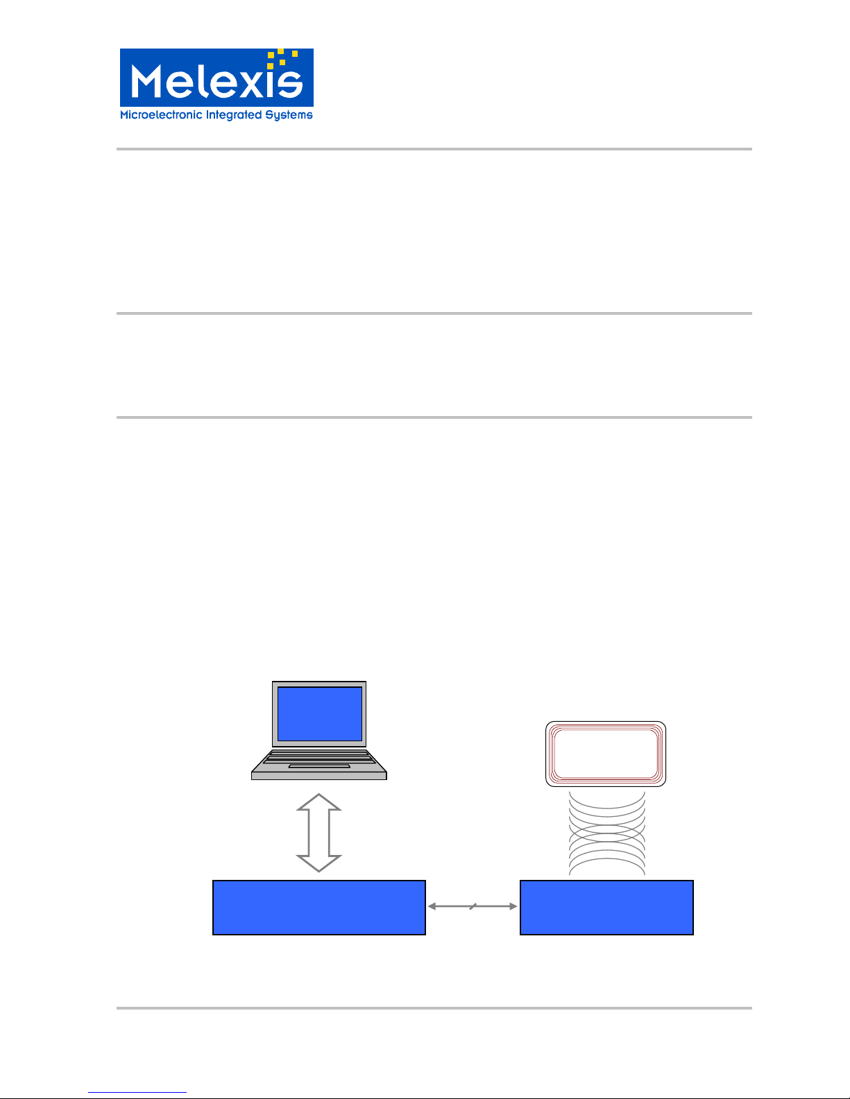
Figure 1: DVK90121 block schematic
UT121
User interface
Universal Development board
Pre-programmed firmware used as an interface
between the PC and the EVB90121
EVB90121
Evaluation board of the Mlx90121
13.56MHz RFID transceiver
RS232
Transponder
MLX90121
Digital interface
Page 2

DVK90121
Development kit for the MLX90121 transceiver
User Manual
390129012102 Page 2 of 13 Development Kit
Rev 006 Apr-2009
Table of Contents
1. UNPACKING THE SYSTEM ........................................................................................................................................................... 3
2. CONNECTING THE SYSTEM.............................................................................................................................................................. 3
3. INSTALLING THE UT121 USER INTERFACE SOFTWARE................................................................................................................ 4
4. WORKING WITH THE UT121 USER INTERFACE SOFTWARE ......................................................................................................... 4
4.1 T
HE FIRST RUN
........................................................................................................................................4
4.2 M
AIN WINDOW
.........................................................................................................................................5
4.3 C
OMMUNICATION STATUS
........................................................................................................................5
4.4 D
EVICE STATUS
.......................................................................................................................................6
4.5 M
AIN MENU
.............................................................................................................................................6
4.6 C
OMMAND TREE
......................................................................................................................................7
4.7 C
OMMAND LIST & REGISTER’S CONFIGURATION
........................................................................................8
4.8 C
OMMUNICATION SCREEN
........................................................................................................................9
5. SET OF COMMANDS........................................................................................................................................................................ 10
5.1 OP
CODES
............................................................................................................................................10
5.2 P
ARAMETERS
........................................................................................................................................10
5.3 K
EY WORDS
..........................................................................................................................................10
5.4..................................................................................................................................................................10
5.5 E
XAMPLES
............................................................................................................................................11
5.4.1 ISO14443 type B .........................................................................................................................11
5.4.2 ISO15693 single/dual sub-carrier................................................................................................11
6. DISCLAIMER..................................................................................................................................................................................... 13
Page 3
DVK90121
Development kit for the MLX90121 transceiver
User Manual
390129012102 Page 3 of 13 Development Kit
Rev 006 Apr-2009
1. Unpacking the system
The DVK90121 is delivered with all the components, documentations and software listed below.
Evaluation board EVB90121 with its specific antenna,
Universal development board,
RS232 and flat cables for PC and EVB90121 connections,
Disk set consisting of the UT121 software and associated documentations.
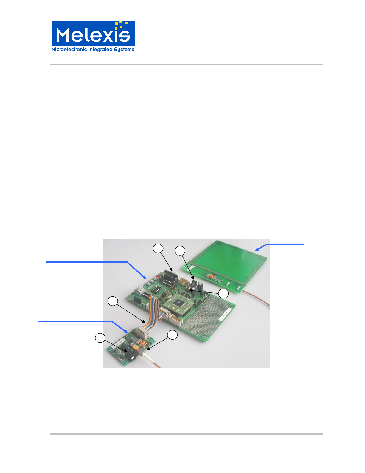
2. Connecting the system
When you start with the development kit DVK90121, please follow the procedure described below.
1) Connect the PCB antenna to the evaluation board EVB90121 using the SMA connector.
2) Connect the EVB90121 with its antenna to the universal evaluation board using the flat cable provided in
the box. Connect the flat cable in the PORTA connector of the universal development board (in the
middle of the three 10 pins connectors in line).
3) Connect the universal development board to the PC using the RS232 cable. The RS232 cable is fitted
into the DB9 connector of the universal development board and the other end is inserted into the COM
port of the PC (DB9 connector). The chosen COM port can be selected in the UT121 software.
4) Connect the Power Supply of the universal development board and EVB90121. Both Power Supplies are
required with a standard 2.1mm barrel connector and must be DC 6 to 9 Volts.
5) Switch on SW1 button on the universal development board.
Figure 2: Connection of the DVK90121
Important Note: The supply must be between 6 to 9 Volts DC. Higher voltage may damage permanently the
DVK90121 circuit.
3
1
2
4
Universal development board
Evaluation board EVB90121
PCB antenna
4
5
Page 4

DVK90121
Development kit for the MLX90121 transceiver
User Manual
390129012102 Page 4 of 13 Development Kit
Rev 006 Apr-2009
3. Installing the UT121 user interface software
To install the software, please insert the compact disc provided with the kit in your computer and simply copy
the UT121 folder on your computer.
The user interface software is now ready to use and can be started by double-clicking on the icon UT121.
Note: To remove the UT121 software, you only need to delete the folder that you created on your PC. The
software doesn’t modify the registry and doesn’t write anything to the system folders.
4. Working with the UT121 user interface software
4.1 The first run
When you execute the UT121 software for the first time, the following window appears. It contains some
explanation about the automatic update,. Please read carefully the text displayed, choose the appropriate
update check interval and press OK button.
Figure 3: First use message
The update check interval will be used to automatically check on the Melexis WEB-site if new updates are
available. The software will ask to the user if he allows the download and the automatic replacement of the
user interface software and firmware. If you choose ‘Never’ as the update interval you will need to update the
program by yourself using the “update” command in the “option” menu.
Page 5

DVK90121
Development kit for the MLX90121 transceiver
User Manual
390129012102 Page 5 of 13 Development Kit
Rev 006 Apr-2009
4.2 Main window
When the UT121 software is executed, the following main window will be displayed. It is structured in several
parts: main menu, device status, communication status, command tree, command list and communication
parts.
Figure 4: UT121 main window
The following chapters describe in detail all parts which compose the main window to familiarize the user with
all the possibilities of the UT121 user interface software.
4.3 Communication status
The UT121 user interface software can communicates the RS232 or USB serial interfaces. The
communication status part displays the status of the selected port. (Use of the DVK90121 is only possible
through RS232 port)
A double-click on the communication status opens the “select port window” which allows the user selecting
the appropriate port and Baud rate. Current data will be updated by pressing on the “update” button.
Figure 5: select port window
If the selected port exists and can be used by the program, it will be opened and “Active” state will be
reported. “Closed” state means that the selected port doesn’t exist on the computer or that an other software
already use it.
Page 6

DVK90121
Development kit for the MLX90121 transceiver
User Manual
390129012102 Page 6 of 13 Development Kit
Rev 006 Apr-2009
Notes:
(1) Communication setup are 57600 baud with RS232.
(2) When the program is closed, the current settings will be saved in the configuration file “ut121Config.cfg”.
Next time the program is executed these settings will be automatically uploaded.
4.4 Device status
The device status shows if a Melexis development kit is connected to the user UT121. Then the name of the
development kit is displayed as shown on the following picture.
If any development kit has been successfully detected, “No device” will be reported in the device status.
4.5 Main menu
The main menu contains several drop-down menus listed and described below. Care should be taken that
the view of the main menu can be modified after an update of the software.
File: All options to save and load a Command List. A Command list is a group which may
contain commands to be executed.
Options: Automatic update options
o Program settings: Option to save the firmware file (hexadecimal file) during an automatic updates procedure. Option to remember
the screen size when the program is closed.
o Auto update options: Option concerning the automatic check interval.
o Connection: Used to specify a proxy settings if necessary
o Update now: The software will find new updates available on the Melexis WEB-site.
Firmware: Used to load the firmware file (hexadecimal files .hex) and to program it into the
DVK90121 through the serial interface. The current firmware into the DVK90121 will
be replaced by the new one.
Documentation: Contains the up-to-date documentation of the DVK90121. Last files are downloaded
when an update is executed
Source: Contains the updated microcontroller source code of the DVK90121. Last version is
downloaded when an update is executed.
Help: To get Libraries and Firmware versions
Page 7

DVK90121
Development kit for the MLX90121 transceiver
User Manual
390129012102 Page 7 of 13 Development Kit
Rev 006 Apr-2009
4.6 Command tree
The command tree window contains a set of commands supported by the DVK90121 organized in groups,
sub-groups and commands. The complete structure is saved in the “ut121ComList.tv” and will be
automatically loaded by the UT121 software when started. The following picture shows an organization’s
example of the command tree window.
As an example, ‘ISO15693 Dual Subcarrier’ group contains several
commands according to Iso15693 standard. If a DVK90121 is
connected and recognized by the software, each command can be
executed separately by clicking on the ‘ ’ icon. The entire group can
also be executed by clicking on the ‘ ’ icon, in this case all
commands include into the corresponding group will be executed one
after the other. All groups may contain several sub-groups with
another set of commands. In the example, the ISO15693 group
contains two sub-groups for Single or Dual sub-carrier specific
commands.
The complete tree structure can be modified by the user and a right
click on the name of the group or sub-group opens a popup menu
with several options. Then the user can append a subgroup, delete
the entire group, append a new command into this group and move
the branch up and down in the list. It is also possible to save the
complete branch (group with its complete structure, sub-groups,
commands and register’s configuration) and to load this branch into
another group. The same menu can be opened with a right-click on
the command. Then the user can delete the command, change its position in the group and editing it.
All commands of the UT121 software are separated in two parts. The Comment part, which is a name chosen
by the user and the Command part, which is the real command send to the DVK90121. This command
cannot be completely defined by the user and should have a fixed definition part to be understood by the
firmware.
To create a new command, right-click on a group to open the popup menu and chose the ‘Append command’
line. Then enter the name (comment) of the command and press “Ok” button. The command will appear with
a red symbol ‘ ’ while the Command part has not been entered. Then, to fill in the Command part, right-click
on the command and chose the “Edit command” button.
Page 8

DVK90121
Development kit for the MLX90121 transceiver
User Manual
390129012102 Page 8 of 13 Development Kit
Rev 006 Apr-2009
4.7 Command list & Register’s configuration
The middle part of a main window represents the list of commands included in the group selected in the
command tree window. Both, Comment and Command parts are displayed.
The commands can be executed by pressing the grey rectangle on the left. Several commands can be
selected and executed altogether by checking the corresponding white square ‘ ’ and by pressing on the
‘ ’ button. If is checked all selected commands will be sent continuously
according to the repeat interval.
Note: If the specified interval is too small and the system cannot execute commands that fast, it will increase
this interval automatically.
To each group or sub-group selected corresponds a specific registers configuration of the MLX90121, and all
commands grouped will be executed with the same registers configuration. When a group or sub-group is
selected, the UT121 software automatically sends the current configuration to the DVK90121 to update the
registers of the MLX90121 transceiver. To access this registers configuration, press onto the ‘ ’ and a
window with all register’s name and hexadecimal values will be displayed. The current value is automatically
updated when this window is closed (press again on the ‘ ’ button).
Access to the registers
configuration of the MLX90121
Group selected
Each command in the command list
can be selected by checking the
square
Button used to send all selected
commands one after the other.
When “Repeat selected”
is
checked, the selected commands
will be sent continuously according
to the repeat interval.
Press onto this grey
rectangle to send the
command
Registers configuration of t
he
MLX90121 transceiver. Start
from address 0 (AnalogConfig
register) to address 11 (LTC
register)
Buttons used to save the
current configuration or
restore the previous one.
Page 9

DVK90121
Development kit for the MLX90121 transceiver
User Manual
390129012102 Page 9 of 13 Development Kit
Rev 006 Apr-2009
4.8 Communication screen
The right side of the main window shows the communication between the computer and the development kit.
Each time the user sends a command, it appears in the screen, followed by the reply of the DVK90121.
The user can specify the number of displayed lines in the “Lines to show” window. It was set up to make sure
the most recent command or reply are displayed without scrolling. Moreover, it is possible to erase the screen
by pushing on the “Clear” button.
Figure 6: Screen of communication
The content of the screen can be automatically written to a file. To do this, the file name must be specified
and the index “Save log to” must be selected.
File name can directly be specified by the user in the “Write to file” editor box or an existing file can be
opened by using “Open file” button.
The program continiously communicates with the reader to test its presence, but these internal commands
are filtered. It is possible to disable the filter with “Disable filter” option, and thus see all communications
between the computer and DVK90121 device.
Communication screen
where all data exchanged
with the development kit are
displayed.
Number of lines
to be displayed
Write to file index
Write to file editor box
Open file button
Erase screen
Disable filter index
Page 10

DVK90121
Development kit for the MLX90121 transceiver
User Manual
390129012102 Page 10 of 13 Development Kit
Rev 006 Apr-2009
5. Set of commands
The firmware controls the communication with the MLX90121 multi-protocol RFID reader. Therefore, it has to
be informed by the UT121 software of the protocol used and the command that needs to be executed. This
chapter describes in detail the set of instructions used for the communication to the DVK90121
(microcontroller firmware).
The different commands are based on Mnemonic assignment defined by several ASCII characters forming
the OP code and defining the protocol used. The OP code is followed by a variable number of Hexadecimal
parameters, which form the command according to the protocol used and specific key words as CRC, BCC.
Notes:
(1) The commands are always defined MSB first in the UT121 software. The firmware will take care of the
data direction according to the standards specification.
(2) Please note that the commands of the UT121 software are case insensitive. Then it is possible for the
user to type commands with capital or small letters.
5.1 OP codes
The OP codes are used to inform the firmware of the protocol used to be able to control the communication.
Iso14b OP code for ISO14443 type B
Iso15 OP code for ISO15693 single and dual sub-carrier
5.2 Parameters
The parameters form the request sends to the transponder according to the standard used. For more
information concerning these parameters, please refer to the ISO norms and the chapter 5.4 below.
5.3 Key words
Some key words are used to facilitate the implementation of the complete commands. For example, all parity
check bytes or words are automatically calculated by the firmware and send with the request.
crc The 16bits CRC (X16 + X12 + X5 + 1) is automatically calculated by the firmware and sends with the request.
slot_X Used to define the number of slots during an Inventory and Write requests of ISO15693. X must be between 1 and 16.
5.4
Page 11

DVK90121
Development kit for the MLX90121 transceiver
User Manual
390129012102 Page 11 of 13 Development Kit
Rev 006 Apr-2009
5.5 Examples
Some examples of commands are described in this chapter.
5.4.1 ISO14443 type B
The DVK90121 allows the communication until the level 3 of the ISO14443 protocol called “Initialization and
anticollision”.
o WUPB (Wake-up type B TAG)
Op code Parameters Key word
Iso14b 050008 crc
‘05’ : Anticol. Prefix byte APF
‘00’ : Application Family Id. AFI
‘00’ : PARAM (WUPB, Nbr of slots)
The 16bits CRC type B is automatically calculated by the firmware and
send with the request.
o Slot-MARKER (slots after REQB/WUPB command)
Op code Parameters Key word
Iso14b 15 crc
‘15’ : Anticol. prefix byte APn 2 slots The 16bits CRC type B is automatically calculated by the firmware and
send with the request.
o ATTRIB
Op code Parameters Key word
Iso14b 1D92036A9600000101 crc
‘1D’ : Attrib command
‘92036A96’ : Identifier PUPI send by the TAG after a
successful REQB/WUPB command
‘00’ : Param 1
‘00’ : Param 2
‘01’ : Param 3
‘01’ : Param 4
The 16bits CRC type B is automatically calculated by
the firmware and send with the request.
5.4.2 ISO15693 single/dual sub-carrier
The DVK90121 allows the communication until the level 3 of the ISO15693 protocol called “Anticolllision and
transmission protocol”.
o READ SINGLE BLOCK (RSB)
Op code Parameters Key word
Iso15 022000 crc
‘02’ : Flags of the request
‘20’ : Read single block command
‘00’ : Block number
The 16bits CRC type B is automatically calculated by the firmware and
send with the request.
Page 12

DVK90121
Development kit for the MLX90121 transceiver
User Manual
390129012102 Page 12 of 13 Development Kit
Rev 006 Apr-2009
O WRITE SINGLE BLOCK (WSB, CSB)
Op code Parameters Key words
Iso15 42210011223344 crc Slot 2
‘42’ : Flags of the request
‘21’ : Write single block command
‘00’ : Block number
‘11223344’ : Data to write
The 16bits CRC is
automatically
calculated by the
firmware and send
with the request.
Two slots send after
the request.
Note: Certain transponder doesn’t support the write command with the option bit set (Flags to 42/43) or
cleared (Flags to 02/03).
O INVENTORY
Op code Parameters Key words
Iso15 06010100 crc Slot 15
‘06’ : Flags of the request
‘01’ : Inventory command
‘01’ : mask length (in this case we
use only 1 bit)
‘00’ : mask value. In this example
mask value is xxxxxxx0
The 16bits CRC is automatically
calculated by the firmware and send
with the request.
Two slots send after the request.
o ANTICOLLISION SEQUENCE
Op code Parameters
Iso15 Inventory
For ASK Perform a complete Inventory sequence. All the UIDs of the transponders in the field will be displayed.
Iso15 Inventory
For FSK Perform a complete Inventory sequence. All the UIDs of the transponders in the field will be displayed.
Page 13

DVK90121
Development kit for the MLX90121 transceiver
User Manual
390129012102 Page 13 of 13 Development Kit
Rev 006 Apr-2009
6. Disclaimer
1) The information included in this documentation is subject to Melexis intellectual and other property rights.
Reproduction of information is permissible only if the information will not be altered and is accompanied
by all associated conditions, limitations and notices.
2) Any use of the documentation without the prior written consent of Melexis other than the one set forth in
clause 1 is an unfair and deceptive business practice. Melexis is not responsible or liable for such altered
documentation.
3) The information furnished by Melexis in this documentation is provided ’as is’. Except as expressly
warranted in any other applicable license agreement, Melexis disclaims all warranties either express,
implied, statutory or otherwise including but not limited to the merchantability, fitness for a particular
purpose, title and non-infringement with regard to the content of this documentation.
4) Notwithstanding the fact that Melexis endeavors to take care of the concept and content of this
documentation, it may include technical or factual inaccuracies or typographical errors. Melexis disclaims
any responsibility in connection herewith.
5) Melexis reserves the right to change the documentation, the specifications and prices at any time and
without notice. Therefore, prior to designing this product into a system, it is necessary to check with
Melexis for current information.
6) Melexis shall not be liable to recipient or any third party for any damages, including but not limited to
personal injury, property damage, loss of profits, loss of use, interrupt of business or indirect, special
incidental or consequential damages, of any kind, in connection with or arising out of the furnishing,
performance or use of the information in this documentation.
7) The product described in this documentation is intended for use in normal commercial applications.
Applications requiring operation beyond ranges specified in this documentation, unusual environmental
requirements, or high reliability applications, such as military, medical life-support or life-sustaining
equipment are specifically not recommended without additional processing by Melexis for each
application.
8) Any supply of products by Melexis will be governed by the Melexis Terms of Sale, published on
www.melexis.com.
© Melexis NV. All rights reserved.
For the latest version of this document, go to our website at:
www.melexis.com
Or for additional information contact Melexis Direct:
Europe, Asia: Americas: Asia:
Phone: +32 1367 0495 Phone: +1 603 223 2362 Phone: +32 1367 0495
E-mail: sales_europe@melexis.com E-mail: sales_usa@melexis.com E-mail: sales_asia@melexis.com
ISO/TS 16949 and ISO14001 Certified
 Loading...