

Page 1
A
C
D
B
QUICK START GUIDE: MICRON PUMP SERIES
Warning: Risk of electrical shock. Carelessness may produce injury or death.
Warning: Hot zone with high temperatures. Risk of burns. Use thermal
protective equipment.
Warning: System under pressure. Risk of burns or particle projection. Use
thermal protective equipment and googles.
Warning: Important information for the correct use of the system. May include
one or several of the previous hazards, and therefore must be kept in mind to
avoid damage and injury.
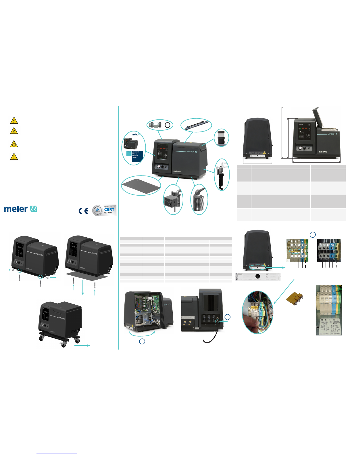
Components and accessories Dimensions/Free space
Mounting the equipment Electrical power connection
Electrical power connection
Warning: The melters/applicators are equipment with current technology and with certain
foreseeable risks. Therefore, only allow qualified personnel with sufficient training and experience
to use, install or repair this equipment.
In case of doubts in the moment of installation, refer to the corresponding instructions manual.
ITEM DESCRIPTION DIMENSIONS
A EQUIPMENT LENGTH 5L 588 mm
10L 671 mm
20L 671 mm
35L 742 mm
B EQUIPMENT WIDTH 5L 339 mm
10L 339 mm
20L 383 mm
35L 435 mm
C EQUIPMENT HEIGHT 5L 481 mm
10L 481 mm
20L 526 mm
35L 673 mm
D EQUIPMENT HEIGHT WITH LID OPEN 5L 628 mm
10L 760 mm
20L 875 mm
35L 1067 mm
R
S
T
N
T N PE F1 F2 F3 N PE
230V 1~ 50 Hz + N + PE
400V 3~ 50 Hz + N + PE
230V 1~ 50 Hz + N + PE
400V 3~ 50 Hz + N + PE
MICRON 20, 35
MODEL No. OUTPUT 1 FHASE 3 FHASES
230 VAC Δ 400 VAC Y
micron 5 2 20.87 A 13.73 A 10.00 A
4 31.30 A 18.45 A 10.87 A
6 41.74 A 27.49 A 16.09 A
micron 10 2 25.22 A 17.86 A 14.35 A
4 35.65 A 21.91 A 14.35 A
6 46.09 A 27.49 A 16.09 A
micron 20 2 27.39 A 19.96 A 16.52 A
4 37.83 A 23.89 A 16.52 A
6 48.26 A 28.24 A 16.52 A
micron 35 2 33.91 A 24.55 A 16.09 A
4 44.35 A 29.35 A 21.30 A
6 54.78 A 37.27 A 26.52 A
Meler Gluing Solutions, S.A
P.I. Los Agustinos, calle G, nave D-43
E - 31160 ORCOYEN Navarra (España)
Tel.: + 34 948 351 110
Fax: + 34 948 351 130
e-mail: [email protected]
www.meler.eu
GLUING SOLUTIONS
3
1
R
S
T
N
2
Ø6-12mm
M8
M8
MICRON 5, 10, 20
M8
M8
Fitting straight short
Warning light
VP system
Low level
detector
Automatic
feeder
Adaptation plate
Hose
Page 2
-
-
-
55
-
-
-
10
ºC
1 2 3 4 5 6 7 8
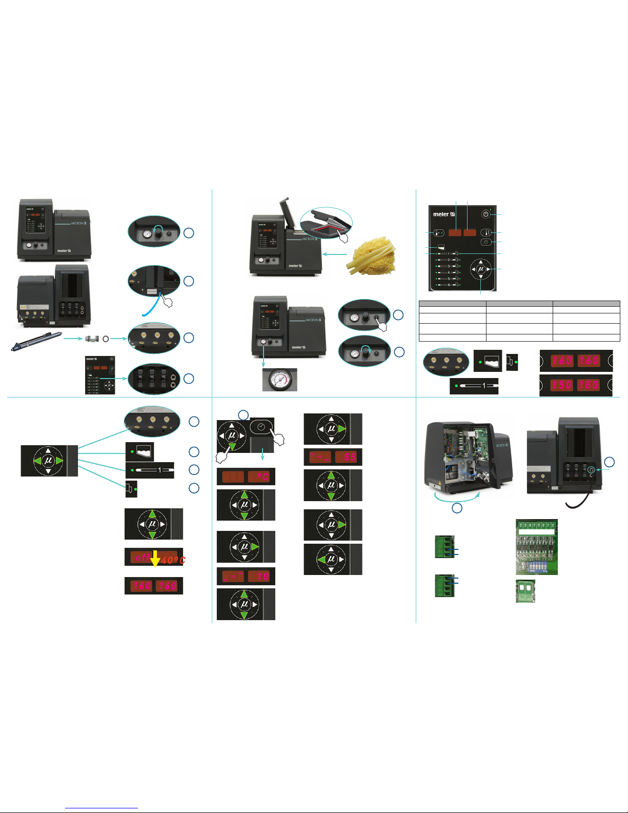
Pneumatic and hose connection Control board
Selecting the overheating value/ Standby Temperature adjustment External I/O connections (optional)
Maximun charge of adhesive
Starting up the melter equipment
P= 0 bar
Ø8mm
P pneumatic
Return to initial
parameter
CN 5 CN 1
CN 4 CN 5
Power card
Control card
Select the element
Modify temperature
Next display to record the value:
Next display to record the value:
Below of 40ºC, temperature display
and heating OFF
Tank’s set point Tª value by default
P hydraulic
Ratio 1:13,6
On/ Off
P
max
= 6 bar
9/16“
6 x
1 3 5
2 4 6
1 3 5
2 4 6
3
4
3 contact NO
4 contact NO
contacto NO
contacto NO
1 common and voltage out +
2 input for inhibitor output 1
3 input for inhibitor output 2
4 input for inhibitor output 3
5 input for inhibitor output 4
6 input for inhibitor output 5
7 input for inhibitor output 6
8 without connection
LED display Component heating Component status
constantly lit constant low temperature
blinking slowly
as need (according to PID
parameters)
temperature near set point
blinking rapidly programming or display change in set point values
off not heating temperature reached
1
1
2
2
3
4
8
1
2
10
9
3
10
7
6
4 5
1. Tank indicator LED
2. Hose indicator LED
3. Gun indicator LED
4. Temperature set point
5. Actual temperature
6. ON/OFF switch
7. Standby function
8. Temperature OK LED and active pump
9. Time scheduling
10. Left/right button - channel selection
11. Up/down button - temperature modification
Tª OK
STANDBY
LOW LEVEL
OUTPUT INHIBITOR
2
1
Ø4-8mm
For more information about the different functions of the control board, refer to the
corresponding instructions manual.
160160
150150
3
1
1
2
4
off
40ºC
160
160
OVERHEATING
10< Increase Tª < 25
STANDBY
25< Decrease Tª % < 55
1
2
1 contact NO
2 contact NO
Default values
 Loading...