


5-phase Stepping Motor Driver
GD-5610
Instructions Manual
(For designers' use)
MN03 2 5-1
Please ensure to read and understand this
Instructions Manual before using the product.
Please keep this Instructions Manual at hand
so that it is always available for reference.

GD-5610
Instructions Manual
Introduction
This Instructions Manual describes the safe and proper method of handling
"5-phase Stepping Motor Driver GD-5610" with emphasis on the specifications,
assuming that our readers are engaged in designing of control devices
incorporating stepping motors.
Please ensure to read and understand this Instructions Manual
before using the product.
Please keep this Instructions Manual at hand
so that it is always available for reference.
-2-

GD-5610
Instructions Manual
Descriptions in this manual on safety matters:
This product must be operated and used properly.
Otherwise, or when it is operated and used erroneously, unforeseen accidents
may occur, causing physical injuries or property damages.
Majority of these accidents can be avoided if you are well informed of
hazardous circumstances in advance.
Consequently, this instructions manual describes all the hazardous and
dangerous circumstances and situations which can be foreseen and anticipated
as well as necessary precautions.
All the above descriptions are being titled by the following symbol-marks and
signal-words, namely:
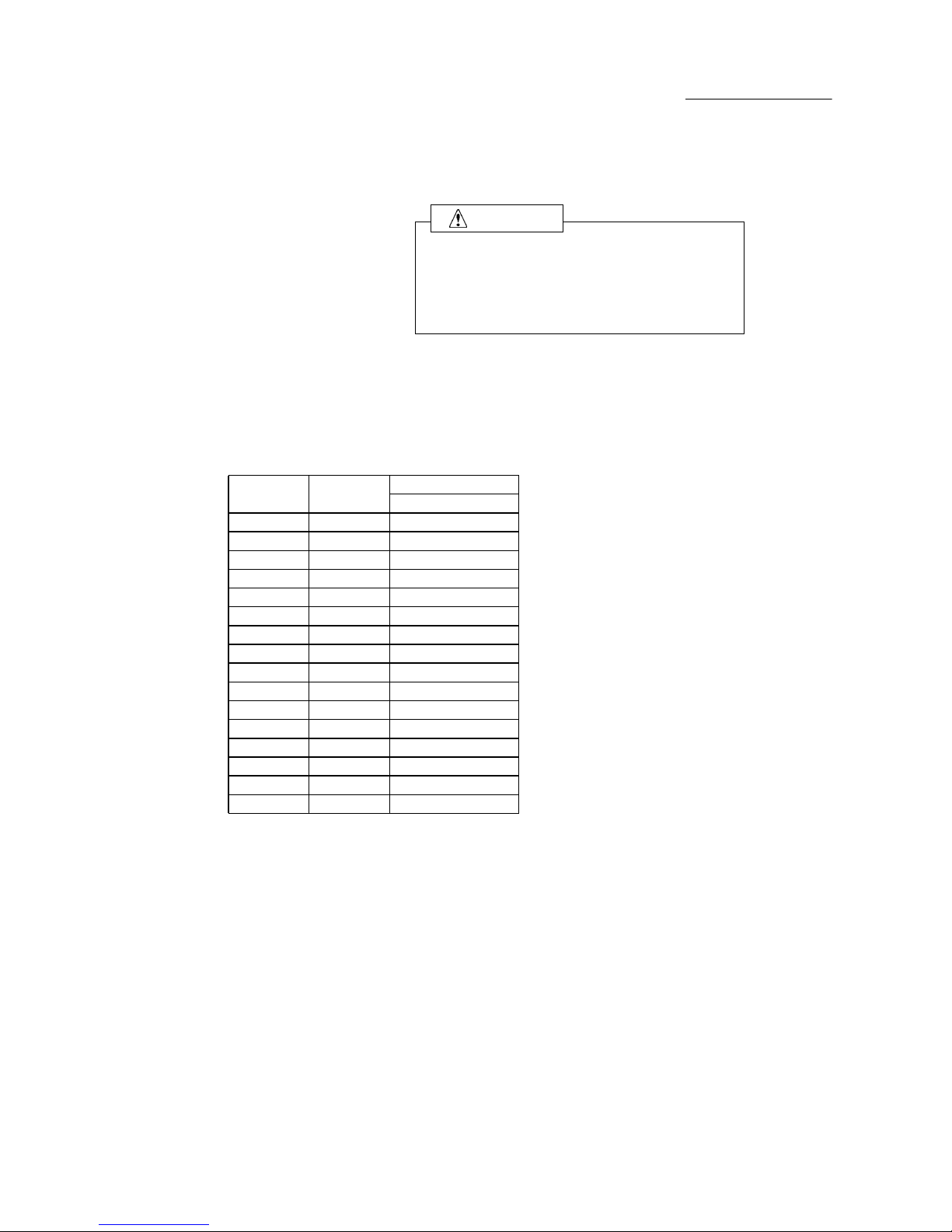
Represents warnings ignorance of which can cause accidents
involving fatal or serious physical injuries, or death.
Represents cautions ignorance of which can cause accidents
involving minor physical injuries or property damages.
WARNING
CAUTION CAUTION
-3-

GD-5610
Instructions Manual
Introduction
Descriptions in this manual on safety matters:
CONTENTS PAGE
1. Safety
1-1. Safety Precautions 6
1-2. Safety Information for Handling 7
Overview
2-1. Characteristics 11
2-2. Product Configuration 11
2-3. Appearance 11
3. Name and Function of Each Section
3-1. Signal I/O Connector(J1) 12
3-2. AC Input/Motor Output Terminal Block(J2, J3) 13
3-3. POWER LED 13
3-4. O.H.A LED 13
3-5.
Operating Section
14
4. Setting
4-1. Setting STEP ANGLE SELECT switch 15
4-2. Setting HOLD CURRENT SELECT switch 16
4-3. Setting DRIVE CURRENT SELECT switch 17
4-4.
Setting HOLD SWITCHING TIME SELECT switch
18
4-5. Setting ROTATE CHARACTERISTIC SELECT switch 18
4-6. Setting MOTOR SELECT switch 18
4-7. Setting PULSE INPUT TYPE SELECT switch 19
5.
Installation
5-1. Conditions for Installation 20
5-2. Mounting Method 21
6. Connection
6-1. Overview of Connection Configuration 22
6-2. Connecting Signal I/O Connector(J1) 23
6-3. Connecting AC Input/Motor Output Terminal Block(J2, J3) 24
6-4. Inputting Power 26
7. Confirmation of Setting and Connection
7-1. Check Points 27
2.
-4-

GD-5610
Instructions Manual
PAGE
8. Maintenance and Check-up
8-1. Maintenance and Check-up 28
8-2. Troubleshooting 29
9. Storing and Disposal
9-1. Storing 30
9-2. Disposal 30
Specifications
10-1. General Specifications 31
10-2. Conforming to Europe standards and UL standards 32
10-3. I/O Signal
(1) Example Circuit Connection 33
(2)
Drive pulse input
(CW,CCW) 34
(3) Motor excitation stop input (M.F) 35
(4) Phase signal output (P.O) 36
(5) Overheat alarm signal output and overheat alarm LED (O.H.A) 37
(6) Step angle switch input (C.S) 38
10-4. Dimensions 39
10-5.
Applicable Motors
40
10-6. Torque Characteristics 41
The main parts which revised by this manual
-5-

GD-5610
Instructions Manual
1.Safety
1-1.Safety Precautions
(1)
This product is not designed or manufactured for application for equipment
requiring high level of reliability such as equipment related to nuclear
energy, aeronautics-related equipment, automobiles, ships, medical appliances
directly handling the human body and equipment that might seriously affect
properties.
(2) Do not use or keep the product in explosive or corrosive environments,
in the presence of flammable gases, locations subjected to splashing water,
fine particles, soot, steam, or exposed to radiation or direct sunshine.
Doing so may cause electric shock, injury or fire.
(3)
This product is designed for use within machinery, so it should be installed
within an enclosure.
Be sure to ground the protective earth terminal of the driver.
(4) Do not transport, move, install the product, perform connections or inspections
when the power is on.
Doing so may cause electric shock, injury or fire.
(5) Only qualified personnel are allowed to transport, move, install the product,
perform connections or inspections.
Failure to do so may cause electric shock, injury or fire.
(6) Do not touch the driver during operation or immediately after stopping.
Doing so may cause burn on the skin due to overheating of the driver.
(7) Ensure to use this product according to the method specified
in the Instructions Manual and within the specifications.
(8) Depending on the operational conditions, the stepping motor may step out when
it is on holding-state or driving-state.
In particular, the load in transport may fall if the motor steps out on the
vertical drive (such as the Z-axis).
Start operation after test run for deliberate confirmation of operation.
(9)
Provide fail-safe measures so that the entire system may operate in a safe
mode even in cases of the external power supply failure, disconnection of the
signal line, or any failure on the driver.
WARNING
CAUTION
-6-

GD-5610
Instructions Manual
1-2.Safety Information for Handling
●Overall:
Do not touch the driver during operation.
Failure to do so may cause electric shock.
indicate terminals on which power voltage
is applied.
Do not touch such terminals while
inputting power and while POWER LED is on.
Doing so may cause electric shock.
Use only an insulated screwdriver to
adjust or set internal switches.
Failure to do so may cause electric shock.
Do not touch the driver during operation
or immediately after stopping.
Doing so may cause burn on the skin due to
overheating of the driver.
●When connecting the AC Input/Motor Output Terminal Block (J2, J3):
Turn the main power OFF.
Failure to do so may cause electric shock.
Securely ground the protective earth
Failure to do so may cause electric shock.
Do not force the power line or the motor
line to be bent or pulled or pinched.
Doing so may cause electric shock or fire.
WARNING
WARNING
WARNING
CAUTION
WARNING
WARNING
WARNING
-7-

GD-5610
Instructions Manual
Erroneous connection may result
in breakage of the motor or the driver.
Correctly connect the motor wiring.
●When setting up the MOTOR SELECT switch:
Erroneous setting may cause burn on the
skin due to overheating of the motor.
Ensure correct setting.
●When setting up the STEP ANGLE SELECT switch:
Erroneous setting may cause breakage of
the machine or injury due to unexpected
rotation of the motor.
Ensure correct setting.
●When setting up the HOLD CURRENT SELECT switch:
A high setting value may cause burn on the
skin due to overheating of the motor.
Do not select a high value beyond the
required.
●When setting up the DRIVE CURRENT SELECT switch:
Erroneous setting may cause burn on the
skin due to overheating of the motor.
Ensure correct setting.
●When setting up the PULSE INPUT TYPE SELECT switch:
Erroneous setting may cause breakage of
the machine or injury due to unexpected
rotation of the moter.
Ensure correct setting.
CAUTION
CAUTION
CAUTION
CAUTION
CAUTION
CAUTION
-8-

GD-5610
Instructions Manual
●When inputting the motor excitation stop (M.F) signal:
Deterioration of the holding power with
the motor may cause breakage of machine
or injury.
Check safety before inputting.
●When installing:
Overheating may cause fire.
Mount it on a noncombustible member.
Keep it away from combustibles.
●When inputting power:
Do not contact with a wet hand.
Doing so may cause electric shock.
indicate terminals on which power voltage
is applied.
Do not touch such terminals while
inputting power and while POWER LED is on.
Doing so may cause electric shock.
Unexpected behavior of the motor may cause
breakage of the machine or injury.
Maintain the state where emergency stop is
enabled at any time.
●When the overheat alarm (O.H.A) signal is output:
Overheating may cause fire.
Stop operation upon output of this signal.
WARNING
WARNING
WARNING
CAUTION
WARNING
CAUTION
-9-

GD-5610
Instructions Manual
●When the overheat alarm (O.H.A) LED comes on
Overheating may cause fire.
Stop operation when this LED comes on.
●When performing maintenance and checking:
Only qualified personnel are allowed to
perform maintenance and checking.
Failure to do so may cause electric shock.
Do not contact with a wet hand.
Doing so may cause electric shock.
indicate terminals on which power voltage
is applied.
Do not touch such terminals while
inputting power and while POWER LED is on.
Doing so may cause electric shock.
Do not replace fuse.
Do not disassemble, repair or modify.
Doing so may cause electric shock, injury
or fire.
WARNING
WARNING
WARNING
WARNING
WARNING
-10-

GD-5610
Instructions Manual
2.Overview
2-1.Characteristics
GD-5610 is a driver for a 5-phase stepping motor with single-phase 100-115V input.
Ten step angles can be selected from angles ranging from a 1/1 division to
a 1/800 division of the basic angle.
HOLD CURRENT and DRIVE CURRENT can be set up.
●
Applicable motors and setting for each motor are given in the table
"10-5. Applicable Motors".
2-2.Product Configuration
The product consists of the main frame and the accessories.
●
GD-5610 One unit
(Complete with terminal block covers)
●
Housing for J1 (51103-1200:Molex) One unit (accessory)
●
Contact for J1 (50351-8100:Molex) 14 contacts (accessories,2 for spares)
2-3.Appearance
0
F
E
D
C
B
A
9
8
7
6
5
4
3
2
1
MOTOR
!
GD-5610
J1
1
12
POWER
OHA
OP2
ON←
OP4
OP5
OP3
OP1
SPI
DRIVE
HOLD
STEP
J3
J2
3
4
5
2
1
1
23L
N
115V~
100V
DHT
RC
0
F
E
D
C
B
A
9
8
7
6
5
4
3
2
1
0
F
E
D
C
B
A
9
8
7
6
5
4
3
2
1
Model Name
Mounting Section
Model Name
Signal I/O Connector
O.H.A LED(RED)
POWER LED(GREEN)
Operating Section
AC Input
Terminal Block
Motor Output
Terminal Block
2
1
J3
5
4
3
RED/GRY
VIO/BLU
BLK/YLW
WHT/ORN
GRN/BRN
GRN
BLK
BLU
RED
ORN
Protective earth
Terminal Block
Mounting Section
GD-5610
100-115V~
5.9A
1φ50/60Hz
Melec Inc.
MADE IN JAPAN
R
-11-

GD-5610
Instructions Manual
3.Name and Function of Each Section
3-1.Signal I/O Connector(J1)
GD-5610
CW+
J1
●Directs the motor to operate CW.
●Shuts off output current to drive the motor.
●Outputs the signal when internal temperature
of the driver has reached approx. 65℃ or more.
1
Motor excitation stop signal input terminal
Step angle switch signal input terminal
Phase signal output terminal
Overheat alarm signal output terminal
CW drive pulse signal input terminal
●Switches the step angle by 1/20 division.
●Outputs the signal when the motor-excitation
state is the excitation home position.
CW-
CCW+
CCW-
M.F+
M.F-
C.S+
C.S-
2
3
4
5
6
7
8
9
10
11
12
P.O+
O.H.A+
CCW drive pulse signal input terminal
●Directs the motor to operate CCW.
P.O-
O.H.A-
-12-

GD-5610
Instructions Manual
3-2.AC Input/Motor Output Terminal Block(J2,J3)
Do not touch the driver during operation.
Failure to do so may cause electric shock.
GD-5610
3-3.POWER LED
POWER LED (GREEN) comes on upon inputting power.
3-4.O.H.A LED
O.H.A LED(RED)comes on when internal temperature
of the driver has reached approx. 65℃ or more.
Motor output terminal
J2
4
J3
3
2
1
5
GRN
BRN
WHT
ORN
BLK
YLW
RED
GRY
VIO
BLU
3
2
1
100115V~
●Outputs current to drive the motor.
AC input terminal
●Power input terminal.
The power supply is connected.
Protective earth terminal
●Protects against electric shock as connected
to the protective earth terminal of the equipment.
N
L
MOTOR
BLU
RED
ORN
GRN
BLK
WARNING
-13-

GD-5610
Instructions Manual
3-5.Operation Section
Do not touch the driver during operation.
Failure to do so may cause electric shock.
GD-5610
STEP ANGLE
SELECT switch
Selects a step angle.
No.1
Selects HOLD CURRENT.
No.6
No.D
HOLD CURRENT
SELECT switch
DRIVE CURRENT
SELECT switch
Selects DRIVE CURRENT.
OFF
ROTATE CHARACTERISTIC
SELECT switch
Selects a characteristic of motor rotation.
OFF
HOLD SWITCHING TIME
SELECT switch
DRIVE/HOLD CURRENT automatic switching time
is selected.
Factory Setting
PULSE INPUT TYPE CELECT
switch
Selects a pulse input type.
OFF
OP4
OP5
Name of Operation Section
Function
OFF
OFF
OFF
MOTOR SELECT
switch
Extend functions
switch
Please use it with OFF.
Selects the applicable motor.
OP1
OP2
OP3
DRIVE CURRENT SELECT switch (DRIVE I.SEL)
DRIVE
4
3
2
1
0
F
E
D
C
B
A
9
8
7
6
5
HOLD
STEP
HOLD CURRENT SELECT switch (HOLD I.SEL)
STEP ANGLE SELECT switch (STEP SEL)
POWER
OHA
POWER LED(GREEN)
OHA LED(RED)
ON
HOLD SWITCHING TIME SELECT switch (DHT SEL)
ROTATE CHARACTERISTIC SELECT switch (RC SEL)
Extend functions switch
OP4
OP3
OP2
OP1
OP5
SPI
DHT
RC
[1P - 2P]
[1s - 150ms]
[ON - OFF]
PULSE INPUT TYPE SELECT switch (SPI SEL)
4
3
2
1
0
F
E
D
C
B
A
9
8
7
6
5
4
3
2
1
0
F
E
D
C
B
A
9
8
7
6
5
MOTOR SELECT switch (OP1,OP2)
WARNING
-14-
GD-5610
Instructions Manual
4.Setting
4-1.Setting STEP ANGLE SELECT switch
Erroneous setting may cause breakage of
the machine or injury due to unexpected
rotation of motor.
Ensure correct setting.
The step angle is set up with the STEP SEL switch.
(1) Set the STEP SEL switch No. to the step angle required.
●
Relationship between the STEP SEL switch No. and the step angle.
(Factory Setting)
●
Driving with two types of step angles are provided by combining
the STEP SEL switch setting and the C.S signal.
0.0018
0.0009
0.036
0.018
0.0072
0.0036
6
7
Switch No.
1234089
1/
Divisions
1/1
1/2
1/4
1/10
1/20
1/4051/800
Step angle(°)
0.72°motor
0.72
0.36
1/100
1/200
1/400
0.18
0.072
1/16
0.045
ABCD----1/8
0.09
1/80
0.009
1/160
0.0045
E
F
CAUTION
-15-

GD-5610
Instructions Manual
4-2.Setting HOLD CURRENT SELECT switch
A high setting value may cause burn on the
skin due to overheating of the motor.
Do not select a high value beyond the
required.
HOLD CURRENT is set up with the HOLD I.SEL switch.
This sets the ratio of HOLD CURRENT to DRIVE CURRENT.
(1) Set the HOLD I.SEL switch No. to the ratio of HOLD CURRENT to
DRIVE CURRENT required.
●
Ratio of HOLD CURRENT
HOLD CURRENT
DRIVE CURRENT
(Factory Setting)
●
HOLD CURRENT changes relative to DRIVE CURRENT setting.
The ratio of HOLD CURRENT set the switch No. to [No.F]:100% represents
the same as the setting for DRIVE CURRENT.
●
The greater the ratio of HOLD CURRENT grows, the more heat the motor
generates when is on holding-state.
9
5055303540
45
52301
8
×100
Switch No.
Ratio of HOLD CURRENT (%)
101520A60B65
Ratio of HOLD CURRENT(%)
=
25
674
E90F
100C70D80
CAUTION
-16-

GD-5610
Instructions Manual
4-3.Setting DRIVE CURRENT SELECT switch
Erroneous setting may cause burn on the
skin due to overheating of the motor.
Ensure correct setting.
DRIVE CURRENT is set up with the DRIVE I.SEL switch.
(1) Set the DRIVE I.SEL switch No. to the setting specified in the table
"10-5. Applicable Motors".
●
Relationship between the DRIVE I.SEL switch and DRIVE CURRENT.
(Factory Setting)
Switch No.
F
2.0
1.8
1.7
1.6
2.1
3.0
1.5
1.4
2.9
2.3
2.4
2.5
2.6
A/phase
2.2
2.7
2.845670123CDE89A
B
CAUTION
-17-

GD-5610
Instructions Manual
4-4.Setting HOLD SWITCHING TIME SELECT switch
DRIVE/HOLD CURRENT automatic switching time is set up
with the DHT SEL switch.
(1) Set the DHT SEL switch.
4-5.Setting ROTATE CHARACTERISTIC SELECT switch
ROTATE CHARACTERISTIC is set up with the RC SEL switch.
(1) Set the RC SEL switch to the specified in the talbe
"10-5. Applicable Motors."
4-6.Setting MOTOR SELECT switch
Erroneous setting may cause burn on the
skin due to overheating of the motor.
Ensure correct setting.
The OP1 and OP2 switches is turned to the setting
corresponding to the motor in use.
(1) Set the OP1 and OP2 switches to the specified in the talbe
"10-5. Applicable Motors."
(Factory Setting)
Hold Switching
Time
DHT SEL1s150ms
ON
OFF
CAUTION
-18-

GD-5610
Instructions Manual
4-7.Setting PULSE INPUT TYPE SELECT switch
Erroneous setting may cause breakage of
the machine or injury due to unexpected
rotation of motor.
Ensure correct setting.
2-pulse input method / 1-pulse input method are
set up by the SPI SEL switch.
(1) Set the SPI SEL switch.
●
When the motor is operated with two pulse signal inputs of CW and CCW,
set the SPI SEL switch to [OFF].
●
When the motor is operated with the pulse signal and direction signal
input, set the SPI SEL switch to [ON].
● In the case that 1-pulse input method is selected, the CCW terminal becomes
direction signal input designating the direction of the motor rotation.
Drive pulse set to the CW terminal(CW+,CW-).
● The input timing is same with 2-pulse input method and 1-pulse input method .
As for input timing, refer to "10-3. (2)Drive pulse input(CW, CCW)"
(Factory Setting)
SPI SEL
Input type
1PULSE (1P)
2PULSE (2P)
ON
OFF
CCW terminal(CCW+,CCW-)
direction set
Photo-coupler OFF: CCW direction
Photo-coupler ON : CW direction
CAUTION
-19-

GD-5610
Instructions Manual
5.Installation
5-1.Conditions for Installation
Mount it on a noncombustible member.
Keep it away from combustibles.
Overheating may cause fire.
(1) Designed for incorporating into equipment used indoors, this product requires
to be installed in the following environment:
●
Area that is free of explosive, corrosive or inflammable gas
●
Indoors (Area not exposed to direct sunshine)
●
Area that ambient temperature and humidity are controlled within the range
set out in the specifications
●
Area protected from dust, salt or iron particles
●
Area not subject to direct vibration or shock
●
Area not subject to splashing water, oil or chemicals
(2) Install the driver at least 10mm away from other equipment.
However, please be installed to a distance of at least 15mm from the
heating element.
●
Please contact us if you are not installed to a distance of at least 15mm
from the heating element.
(3) Considering heat release, control the ambient temperature around the driver
within the specified value.
●
Take measures against accumulation of heat such as allowing generous space
ようにする。
around the driver or installing a fan so that heat release is taken care of.
●
Install the driver securely in contact with metal or other substance with
adequate heat conductivity.
(4) In the case that an overheat alarm signal is output, perform the cooling measure of
the mounting plate is enlarged or compulsion air cooling etc.
Use the driver on the condition that an overheat alarm signal is not output.
(5)
Do not allow standing or placing anything heavy on the product.
WARNING
10mm or more
10mm or more
15mm or more
Driver
10mm or more
Driver
10mm or more
heating
element
-20-

GD-5610
Instructions Manual
5-2.Mounting Method
The following items are required:
●
M-4 screw (8mm or more in length):
4
●
M-4 spring washer:
4
●
M-4 flat washer:
4
(1) Temporarily fix the product at the round hole.
(2) Fix the product at the three cutouts.
(3) Fasten the screw in the round hole.
●
Mounting example
Fixing with a screw
Fixing with a screw Fixing with a screw
M-4 screw
M-4 spring washer
M-4 flat washer
0
F
E
D
C
B
A
9
8
7
6
5
4
3
2
1
MOTOR
!
GD-5610
J1
1
12
POWER
OHA
OP2
ON←
OP4
OP5
OP3
OP1
SPI
DRIVE
HOLD
STEP
J3
J2
3
4
5
2
1
1
23L
N
115V~
100V
DHT
RC
0
F
E
D
C
B
A
9
8
7
6
5
4
3
2
1
0
F
E
D
C
B
A
9
8
7
6
5
4
3
2
1
Fixing with a screw
2
1
J3
5
4
3
RED/GRY
VIO/BLU
BLK/YLW
WHT/ORN
GRN/BRN
GRN
BLK
BLU
RED
ORN
-21-

GD-5610
Instructions Manual
6.Connection
6-1.Overview of Connection Configuration
GD-5610
●
Connect only one motor to one driver.
●
Use twisted pair wire for the CW/CCW input signal line.
●
Provide shielding for the signal line where considerable noise is generated.
●
Use the wire material of the characteristic that is difficult to burn.
●
Provide ferrite core for the motor line if it generates significant noise.
〔Example configuration〕
The metallic enclosure and shielded wires and ferrite core work to shield noise.
CWP
J1
CW+
1
R.GND
User
controller
CCWP
+COM
+COM
R.GND
2
3
4
5
6
7
8
9
10
11
12
C.S
O.H.A
P.O
M.F
CCWP
CWP
CWCCW+
CCWM.F+
M.F-
C.S+
J3
P.O+
O.H.A+
C.S-
J2
1
2
3
5
3
4
1
2
Protective earth
terminal for the
equipment (PE)
(O.75mm2 or more)
Motor
Single-phase 100-115V
N
L
Twisted
pair wire
Single-phase 100-115V
P.O-
O.H.A-
User
controller
Driver
Metal Enclosure
Metal Enclosure
Grounding
Shield
Metal Enclosure
Motor
Ferrite core
Grounding Grounding
-22-

GD-5610
Instructions Manual
6-2.Connecting Signal I/O Connector(J1)
The following items are required:
●
Housing for J1 (51103-1200:Molex): One unit (accessory)
●
Contact for J1 (50351-8100:Molex): 12 contacts (accessories)
●
Manually operated crimping tool
for AWG28-22(57295-5000:Molex): One unit
(1) Crimp the contact to the cable used for wiring.
(2) Insert the contact into the housing.
Make sure that the housing No. and the connector No. on the main frame are
matched before inserting the contacts.
(3) Connect the housing to the connector on the main frame.
●
The contacts for J1 are 12 pieces.
●
When inserting, keep pushing J1 housing into the connector until it is locked.
Also, check if the contacts are not displaced from the housing.
●
In wiring, isolate the J1 signal lines from equipment that may be
さい。
a source of noise, the power line and the motor line.
(Surface on which the contacts are inserted)
Housing for J1
GD-5610
●
Use a signal cable of AWG26(0.15mm2) or more in diameter.
12 11 10 9 8 7 6 5 4 3 2 1
CWP
J1
CW+
R.GND
User
controller
CCWP
+COM
+COM
R.GND
C.S
O.H.A
P.O
M.F
CCWP
CWP
CWCCW+
CCWM.F+
M.F-
C.S+
P.O+
O.H.A+
Step angle
switch input
〈Wiring〉
〈Crimping〉
〈Connection〉〈Insertion〉
Contact Housing
1
2
3
4
5
6
7
8
9
10
11
12
1
2
3
4
5
6
7
8
9
10
11
12
C.S-
Overheat alarm
signal output
Phase signal output
Motor excitation
stop input
Drive pulse input
Drive pulse input
P.O-
O.H.A-
-23-

GD-5610
Instructions Manual
6-3.Connecting AC Input/Motor Output Terminal Block(J2,J3)
Turn the main power OFF.
Failure to do so may cause electric shock.
Securely ground the protective earth
Failure to do so may cause electric shock.
Do not force the power line or the motor
line to be bent or pulled or pinched.
Doing so may cause electric shock or fire.
Erroneous connection may result
in breakage of the motor or the driver.
Correctly connect the motor wiring.
The following items are required:
●
Crimping terminal
8
(TMEV1.25-3: Nichifu or the equivalent)
●
Manually operated crimping tool for AWG22-16 One unit
(NH-11: Nichifu or the equivalent)
(1) Turn power of the equipment [OFF].
(2) Crimp the crimping terminals to the cable used for wiring.
(3) Remove the covers of terminal block, then connect.
(4) Fix the terminal block covers after completing connection.
GD-5610
J2
〈Wiring〉〈Connection〉
〈Crimping〉
Crimping terminal
1
2
3
N
L
NEUTRAL
LIVE
Single-phase 100-115V
Protective earth terminal
for the equipment (PE)
100-
115V~
Protective earth
terminal
〔Protective earth terminal ・ AC input terminal〕
WARNING
WARNING
WARNING
CAUTION
-24-

GD-5610
Instructions Manual
●
the protective earth terminal of the equipment (PE).
●
Use a protective earth cable and power cable of AWG18(0.75mm2) or more
in diameter.
GD-5610
GD-5610
●
Color indications for the motor crimping terminals (1~5) represent colors
of the leads of the motor.
●
Use a motor cable of AWG20(0.5mm2) or more diameter.
●
When use a motor cable more than 5m, contact our office.
〔Motor output terminal〕
J3
MOTOR
〈Wiring〉〈Connection〉
〈Crimping〉
Crimping terminal
Motor
Green/Brown
Leads of the motor
1
2
3
4
5
GRN
BRN
WHT
ORN
BLK
YLW
RED
GRY
VIO
BLU
BLU
RED
ORN
GRN
BLK
White/Orange
Black/Yellow
Red/Gray
Violet/Blue
J3
MOTOR
Motor
Red
Orange
Green
Black
Blue
1
2
3
4
5
GRN
BRN
WHT
ORN
BLK
YLW
RED
GRY
VIO
BLU
BLU
RED
ORN
GRN
BLK
〈Wiring〉〈Connection〉
〈Crimping〉
Crimping terminal
Leads of the motor
-25-

GD-5610
Instructions Manual
6-4.Inputting Power
Do not contact with a wet hand.
Doing so may cause electric shock.
indicate terminals on which power voltage
is applied.
Do not touch such terminals while
inputting power and while POWER LED is on.
Doing so may cause electric shock.
Unexpected behavior of the motor may cause
breakage of the machine or injury.
Maintain the state where emergency stop is
enabled at any time.
(1) Input power (single-phase 100-115V) into the cable connected to No.2
and No.3 terminals of J2.
WARNING
WARNING
CAUTION
-26-

GD-5610
Instructions Manual
7.Confirmation of Setting and Connection
7-1.Check Points
(1)
This product requires different switch setting and motor wiring depending on
the motor used.
Check if the switch setting and the motor wiring are correctly performed.
(2)
(3) Check if the terminal block covers are fixed on J2 and J3.
Setting of PULSE INPUT TYPE
SELECT switch
OFF/ON
Connection of J1
Remarks
Check
Check Points
Switch No.
Setting of STEP ANGLE
SELECT switch
Setting of HOLD SWITCHING TIME
SELECT switch
Setting of DRIVE CURRENT
SELECT switch
Connection of J3
AC input terminal (L,N)
Switch No.
Terminal block cover
Motor output terminal
Terminal block cover
OFF/ON
OFF/ON
Setting of MOTOR SELECT switch
Setting of Extend functions
switch
Setting of HOLD CURRENT
SELECT switch
Connection of J2
OFF/ON
Switch No.
Setting of ROTATE
CHARACTERISTIC SELECT switch
OFF/ON
-27-

GD-5610
Instructions Manual
8.Maintenance and Check-up
8-1.Maintenance and Check-up
Only qualified personnel are allowed to
perform maintenance and checking.
Failure to do so may cause electric shock.
Do not contact with a wet hand.
Doing so may cause electric shock.
indicate terminals on which power voltage
is applied.
Do not touch such terminals while
inputting power and while POWER LED is on.
Doing so may cause electric shock.
Do not replace fuse.
Do not disassemble, repair or modify.
Doing so may cause electric shock, injury
or fire.
(1)
As for a maintenance inspection the engineer of the specialty shall do it.
(2) We recommend that the following check-ups should be performed periodically:
●
Checking for any loosened screws on the terminal block and
contacts on the connectors.
●
Checking for any flaw and crack on the cabling.
(3) In case of failure, return the driver to us and have it repaired.
WARNING
WARNING
WARNING
WARNING
-28-

GD-5610
Instructions Manual
8-2.Troubleshooting
1.
POWER LED does not ・Connection of power supply. ・Wiring error with power supply.
come on. ・Value of power voltage. ・Power voltage failure.
・Driver failure.
2.
The motor is not excited. ・Connection of the motor to ・Wiring error with the motor
(It can be easily
the driver. and the driver.
rotated by hand.)
・ON/OFF status of the M.F
・The M.F signal is input.
signal. ・Driver failure.
3.
The motor does not rotate.
・The same check items as
The motor behaves those under item 2 above.
abnormally. ・Setting of the PULSE INPUT ・Wrong setting for the pulse
The motor steps out. TYPE SELECT switch. input type.
・Connection of the pulse signal. ・Wiring error with the pulse
signal line.
・Voltage and wave form of the ・Pulse signal of wrong
pulse signal. specifications.
・Setting of the DRIVE CURRENT ・DRIVE CURRENT is too low.
SELECT switch.
・Setting of the STEP ANGLE ・Wrong setting for the step
SELECT switch.
angle.
・ON/OFF status of the C.S
・The C.S signal is input.
signal. ・Driver failure.
・Motor failure.
4.
The motor steps out ・Starting pulse speed. ・Starting pulse signal speed is
during acceleration.
too high.
・Acceleration time. ・Acceleration time is too short.
5.
The motor generates ・Setting of the DRIVE CURRENT ・DRIVE CURRENT is higher than
excessive heat.
SELECT switch.
the setting for the applicable
motor.
・Setting of the HOLD CURRENT ・The setting for HOLD CURRENT
SELECT switch.
is too high.
・Setting of the MOTOR SELECT ・Wrong setting for the motor
switch. selection.
6.
Overheat alarm signal ・Ambient temperature around ・Ambient temperature is too high
is output. the driver. (50℃ or more).
Short-circuiting of the motor output terminal may cause the driver to fail.
●
Short-circuiting between the motor output terminal and the earth terminal (PE)
●
Short-circuiting between the motor output terminal and the power line
●
Short-circuiting between the motor output terminal and the motor output terminal
●
Wiring error or snapping of the motor output lines
When the failure phenomenon cannot be remedied, contact our office.
Trouble
Check Item
Assumed Cause
-29-

GD-5610
Instructions Manual
9.Storing and Disposal
9-1.Storing
(1) Keep the product in the following environment:
●
Area that is free of explosive, corrosive or inflammable gas
●
Indoors (Area not exposed to direct sunshine)
●
Area that ambient temperature and humidity are controlled within the range
set out in the specifications
●
Area protected from dust, salt or iron particles
●
Area not subject to direct vibration or shock
●
Area not subject to splashing water, oil or chemicals
(2)
Do not allow standing or placing anything heavy on the product.
9-2.Disposal
(1) Dispose of the product as industrial waste.
-30-

GD-5610
Instructions Manual
10.Specifications
10-1.General Specifications
Single-phase 100-115V(50/60Hz) *1
●Rated power at DRIVE: 〔DRIVE I.SEL ⇒ No.F set up〕*2
AC100V : 5.9A AC115V : 5.9A
●Rated power at HOLD: 〔DRIVE I.SEL ⇒ No.F, HOLD I.SEL ⇒ 40% set up〕
AC100V : 0.5A or less AC115V : 0.5A or less
●DRIVE CURRENT 1.4A/phase~3.0A/phase (16 levels)
●HOLD CURRENT 10%~100% of DRIVE CURRENT (16 levels)
●Drive pulse input
(CW, CCW)
Photo-coupler input
●Motor excitation stop input (M.F) Photo-coupler input
●Step angle switch input
(C.S) Photo-coupler input
●Phase signal output (P.O) O/C output
●Overheat alarm signal output
(O.H.A) O/C output
●DRIVE CURRENT selection
(DRIVE I.SEL)
●HOLD CURRENT selection (HOLD I.SEL)
●STEP ANGLE selection (STEP SEL)
●PULSE INPUT TYPE selection
(SPI SEL)
●HOLD SWITCHING TIME selection
(DHT SEL)
●ROTATE CHARACTERISTIC selection (RC SEL)
●MOTOR selection
(OP1,OP2)
Indoor (Exposure to direct sunshine is not allowed.)
Without any explosive, corrosive or inflammable gas, oil mist, or dust
(At ordinary temperature and humidity)
*1 Input voltage range is single-phase 100-115V±10%.
*2 Power demand varies with rotation speed, a load, etc.
*3 Including screws and terminal blocks.
Atmosphere
Supply Power
(No freezing allowed)
Input Signal
Output Signal
Operating Ambient
Temperature
(No condensation allowed)
0℃ ~ +50℃
80%RH or less
-10℃ ~ +55℃
80%RH or less
H149.5 × W170 × D59 (mm) *3
0.9 kg
500VDC: 100MΩ or more
1500VAC: for one minute
500VDC: 100MΩ or more
Withstanding
Vibration
No abnormality should be found after a vibration test
at 10~55Hz, 0.15mm P-P.
AC terminal - signal terminal
Insulated
Withstanding Voltage
Exterior Dimensions
Weight
Insulation Resistance
Motor output current
(No condensation allowed)
Operating Ambient
Humidity
Storing Temperature
Storing Humidity
1500VAC: for one minute
Function of Operating
Sections
Altitude
Up to 1000m above sea level
(No freezing allowed)
-31-

GD-5610
Instructions Manual
10-2.Conforming to Europe standards and UL standards
This product conducted the validation test of low voltage directive and EMC directive
with TÜV(TÜV Japan) for self-declaration of the CE making.
(1) Safety standards
EN 61800-5-1
UL508C
*1
●Low voltage directive
This product is designed for use as a built-in component.
・Install the product within an enclosure in order to avoid contact with the hand.
・Securely ground the protective earth terminals.
●Installation conditions
Protective class:
Ⅰ
Overvoltage category:
Ⅱ (EN 61800-5-1), Ⅲ (UL508C)
Pollution degree:
Class 2
Protective type: IP10
*1 Warning for UL standards
This product has no provision for motor over temperature protection.
Motor over temperature protection is required in the end use product.
(2) EMC standards
EN 61800-3
●EMC derective
This product conducted EMC measurement with the system configuration for EMC.
・EMC characteristic may vary depending on the configuration of the equipment that
contains the driver or stepping motor. Be sure to conduct EMC measurement with
the product assembled in your equipment.
The metallic enclosure and shielded wires and ferrite core work to shield noise.
Configuration
User
controller
(Protective
classⅡ)
GD-5610
Metal Enclosure
Metal Enclosure
AC input
Transformer with
reinforced insulation
Shield
Metal Enclosure
Motor
Grounding
Ferrite core
GroundingGrounding
-32-

GD-5610
Instructions Manual
10-3.I/O Signal
(1) Example Circuit Connection
GD-5610
●
Power supply for I/O circuit shall be reinforced or double insulation
against hazardous voltage such as 100Vac mains.
Proving SELV≦60Vdc power supply circuit is necessary.
Example connection
of the user controller
CW+
5
CWP
CW-
6
3
12
11
4
1
2
9
10
CWP
CCW+CCWP
CCW-CCWP
+24V
M.F++COM
M.F-M.F
C.S
C.S++COM
C.S-
R.GND
7
8
+Vo
R
P.O
P.O+
R.GND
R
O.H.A O.H.A+
-Vo
(J1)
GND
GND
26LS31
Y
Z
26LS31
Y
Z
160Ω
160Ω
1.3kΩ
1.3kΩ
Photo-coupler
+24V
Photo-coupler
Photo-coupler
Photo-coupler
Photo-coupler
Photo-coupler
Photo-coupler
Photo-coupler
P.O-
O.H.A-
-33-

GD-5610
Instructions Manual
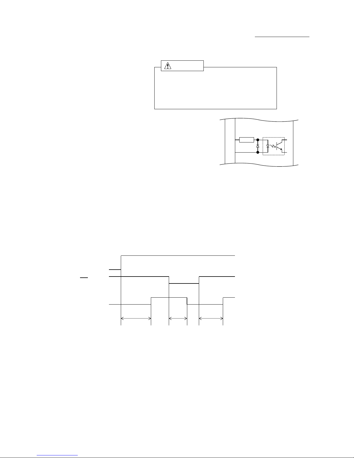
(2)
Drive pulse input(CW, CCW)
① Operating current range : 9mA~27mA
The photo-coupler turns on with GD-5610
inter-terminal voltage of 3.1 V~5.5 V.
(Photo-coupler diode VF≒ 1.6 V)
② Timing chart
[To the line driver 26LS31]
t1≧0.5μs, t2≧0.5μs, tf,tr≦1μs
t3≧1μs, t4>1μs
Maximum response frequency : 1MHz
(Duty 50%)
●
The shaded area ( ) indicates light emission from the photo-coupler,
and the motor is driven at the rising edge ( ).
"t4" greatly varies according to the inertial moment including that of the motor.
③ Automatic switching for DRIVE/HOLD
DRIVE
HOLD HOLD
t1
t1≒150ms (HOLD SWITCHING TIME SELECT switch : OFF)
t1≒1s (HOLD SWITCHING TIME SELECT switch : ON)
●
Inputting drive pulse causes the current output to the motor to change from
HOLD CURRENT to DRIVE CURRENT, which returns to HOLD CURRENT in "t1".
DRIVE CURRENT continues if pulse is input on driving-state.
④ Direction of rotation
CCW
CW(Clockwise)
CWP
CCWP
Motor
current
CW+ (CCW+)
26LS31
Y
Z
CW- (CCW-)
CWP
90%
10%
t1 t2
tf tr
t3 t4
CCWP
CW-
CCW+
CCW-
CW+
3
4
1
2
(J1)
Photo-coupler
160Ω
160Ω
Photo-coupler
-34-
GD-5610
Instructions Manual
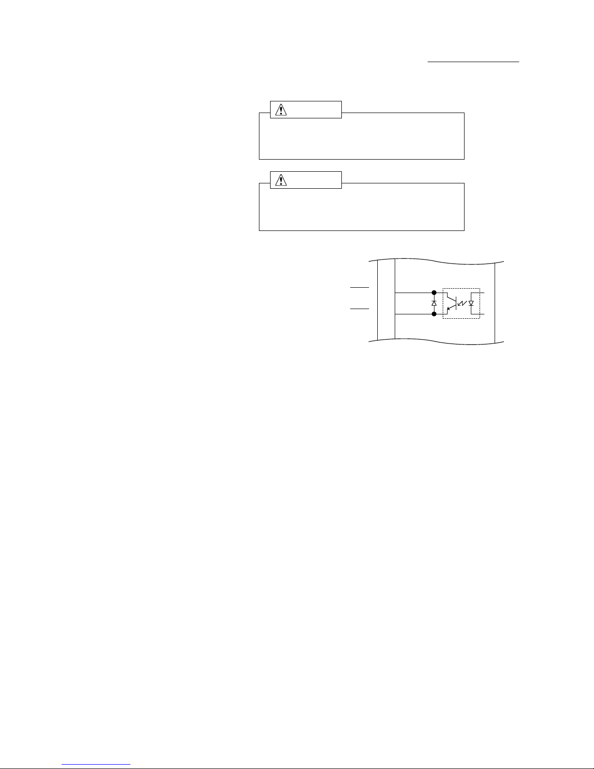
(3) Motor excitation stop input(M.F)
Deterioration of the holding power with
the motor may cause breakage of the machine
or injury.
Check safety before inputting.
① Operating current range : 2.6mA~19.5mA GD-5610
The photo-coupler turns on with
inter-terminal voltage of 4.5V~26.4V.
(Photo-coupler diode VF≒ 1.1 V)
●
Motor output current is shut off with the photo-coupler ON.
At this time, motor torque changes to detent torque.
●
When this signal is input, motor torque may be lost, resulting in failure to
retain the load transported.
In particular, this risk is high with the vertical drive (such as the Z-axis).
② Timing chart
Supply
power
M.F
t1 t2
t1≦1.5s (t1:Time required for the motor to be enabled.)
t2≦5ms (t2:Time required for the motor output current to be shut off.)
t3≦100ms (t3:Time required for the motor to be enabled.)
t3
Motor
excitation
OFFONOFFONON
ON
5
6
M.F+
M.F-
(J1)
Photo-coupler
1.3kΩ
CAUTION
-35-

GD-5610
Instructions Manual
(4) Phase signal output(P.O)
① Output current
a.
IC≦6mA, VCE<2V
b.
IC≦2mA, VCE(sat)<0.6V GD-5610
VCEO≦30V
●
In case of the excitation home position, the signal is output.
(photo-coupler ON)
●
In case of simultaneously using P.O signal and C.S signal,
input C.S signal while P.O signal is being output to switch the step angle.
Otherwise, P.O signal may not be output.
② Timing chart
●
P.O output timing (for 1/1 STEP)
CWP
CCWP
P.O
7.2°
(For a motor with the basic angle of 0.72°)
●
P.O output time
1/1 STEP: once in 10 pulses 1/8 STEP: once in 80 pulses
1/2 STEP: once in 20 pulses 1/16 STEP: once in 160 pulses
1/4 STEP: once in 40 pulses 1/80 STEP: once in 800 pulses
1/10 STEP: once in 100 pulses 1/160 STEP: once in 1600 pulses
1/20 STEP: once in 200 pulses
1/40 STEP: once in 400 pulses
1/100 STEP: once in 1000 pulses
1/200 STEP: once in 2000 pulses
1/400 STEP: once in 4000 pulses
1/800 STEP: once in 8000 pulses
5678123410901
2
7
8
P.O+
(J1)
Photo-coupler
P.O-
-36-
GD-5610
Instructions Manual
(5) Overheat alarm signal output(O.H.A)
Overheating may cause fire.
Stop operation upon output of this signal.
Overheating may cause fire.
Stop operation when this LED comes on.
① Output current
a.
IC≦6mA, VCE<2V
b.
IC≦2mA, VCE(sat)<0.6V GD-5610
VCEO≦30V
●
Use overheat alarm signal output(O.H.A)without fail.
●
In case of internal temperature of the driver reaches approx. 65℃ or more,
this signal is output (photo-coupler ON) and O.H.A LED comes on.
At this time the motor output current is not blocked.
●
When this signal is output, stop operation and check if there is any
abnormality occurring with the motor and the driver.
●
Perform the cooling measure of the mounting plate is enlarged or
compulsion air cooling, for example, if this signal is output
while no abnormality is detected.
●
Continuous operation is possible unless this signal is output.
9
10
O.H.A+
(J1)
Photo-coupler
O.H.A-
WARNING
WARNING
-37-

GD-5610
Instructions Manual
(6)
Step angle switch input(C.S)
① Operating current range : 2.6mA~19.5mA
The photo-coupler turns on with GD-5610
inter-terminal voltage of 4.5V~26.4V.
(Photo-coupler diode VF≒ 1.1 V)
●
Step angle division is switched to 1/20 divisions with the photo-coupler ON.
The setting for the STEP ANGLE SELECT switch is ignored.
●
No displacement occurs even if the step angle is switched by the C.S signal.
② Timing chart
Number of divisions 1/20divisions Number of divisions
of STEP SEL switch of STEP SEL switch
ON OFF
C.S
t1≧30ms
t2≧ 1ms
●
Switching the step angle by the C.S signal requires time t1 and t2 before
and after inputting drive pulse.
③ STEP ANGLE SELECT switch and C.S signal
〔When the C.S signal is input〕
1/20 (0.036°)
8
2
1/2
1/4
1/10
0.0009
1/400
1/800
0.0018
9
1/20
1/40
1/10056
0.36
1
0.18
0.0036
0.018
0.0072
0.036
0.072
7
1/200
CWP
CCWP
t1t2t1
0.72
1/
Divisions
Switch No.
t2
A--34
0
1/1
Step angle(°)
0.72°motor
B--
C
1/8
0.09
F
1/160
0.0045
D
1/16
0.045
E
1/80
0.009
11
12
C.S+
C.S-
(J1)
Photo-coupler
1.3kΩ
-38-

GD-5610
Instructions Manual
10-4.Dimensions
(Unit:mm)
149.5
135 (14.5)
142
14
14
170
(5) 160 (5)
(59)
7.62
0
F
E
D
C
B
A
9
8
7
6
5
4
3
2
1
MOTOR
!
GD-5610
J1
1
12
POWER
OHA
OP2
ON←
OP4
OP5
OP3
OP1
SPI
DRIVE
HOLD
STEP
J3
J2
3
4
5
2
1
1
23L
N
115V~
100V
DHT
RC
(3)
16.5 20 16.5
53
(59)
(3)
37
20
16
0
F
E
D
C
B
A
9
8
7
6
5
4
3
2
1
0
F
E
D
C
B
A
9
8
7
6
5
4
3
2
1
R2.254.5
2
1
J3
5
4
3
RED/GRY
VIO/BLU
BLK/YLW
WHT/ORN
GRN/BRN
GRN
BLK
BLU
RED
ORN
GD-5610
100-115V~
5.9A
1φ50/60Hz
Melec Inc.
MADE IN JAPAN
R
-39-

GD-5610
Instructions Manual
㸯㸮㸫㸳㸬$SSOLFDEOH0RWRUV
R1
ە
GD-5610 can drive a 5-phase stepping motors of 2.4 - 2.8A/phase.
PKP564FN24A(B)2
PKP566FN24A(B)2
PKP569FN24A(B)2
PKP564N28A(B)2
PKP566N28A(B)2
PKP568N28A(B)2
PK569H-A(B)
PK596H-A(B)
PK599H-A(B)
SF5601-9251
SF5602-9251
SF5603-9251
( ) : Both axes
ە
When use a non-applicable motor, contact our office.
Fig.12
0.72 2.8
D
OFF
OFF
OFF
Fig.10
Fig.11
ڧPP
0.72 2.8
D
ڧPP
2.8
2.8
D
Basic
Angle
r
Current
(A/phase)
0.72
0.72
OP1
switch
OP2
switch
0.72 2.4
Basic
Angle
r
Current
(A/phase)
D
ڧPP
ORIENTAL MOTOR CO., LTD.
DRIVE
I.SEL
switch
RC SEL
switch
9
Torque Data
Fig. No.
Fig.1
Fig.2
Fig.3
Fig.4
ON
OFF
OFF
OFF
OFF
OFF Fig.5
Fig.6
OP1
switch
OFF
OFF
OFF
OFF
ON
ON
OP2
switch
Torque Data
Fig. No.
ڧPP
ڧPP
Fig.7
Fig.8
Fig.9
DRIVE
I.SEL
switch
SANYO DENKI CO., LTD.
RC SEL
switch
-40-

GD-5610
Instructions Manual
10-6.Torque Characteristics
(1)
Representations in the torque characteristics table are made in terms of the
motor rotation speed (s-1) vs. torque (N・m).
Motor rotation speed (s-1) and drive pulse frequency (Hz) are converted as follows:
360°
Step angle
●
Maximum value of the rotation speed is 60s-1 at 0.72゜ motor.
(2) The Maximum Starting Pulse Rate is represented as "fs" by the value at zero
inertial load.
(3) Upon operation, provide adequate allowance for torque.
(4)
The stepping motor may attain high temperature, depending on the operational
conditions.
Use the stepping motor according to the Instructions Manual produced
by motormakers.
×=Drive pulse input frequency(Hz)
-1
)
-41-

GD-5610
Instructions Manual
R1
Fig.1
OP1,OP2 = ON,ON
AC100V
1.0
0.8
0.6
0.4
0.2
HOLD 40㸣 = 0.30N࣭m
2
4
6
8
10
TORQUE(N࣭m)
INPUT CURRENT(A)
0.02 0.1 1 10 100
(s )
-1
RC SEL = OFF
PULLOUT TORQUE
INPUT CURRENT
fs
PKP564FN24A(B)2
2.4A/PHASE
GD-5610
DRIVE I.SEL = No.9(2.4A/PHASE)
Fig.2
OP1,OP2 = ON,ON
AC100V
2.0
1.6
1.2
0.8
0.4
HOLD 40㸣 = 0.53N࣭m
2
4
6
8
10
TORQUE(N࣭m)
INPUT CURRENT(A)
0.02 0.1 1 10 100
(s
)
-1
RC SEL = OFF
PULLOUT TORQUE
INPUT CURRENT
fs
PKP566FN24A(B)2
2.4A/PHASE
GD-5610
DRIVE I.SEL = No.9(2.4A/PHASE)
Fig.3
OP1,OP2 = ON,ON
AC100V
2.5
2.0
1.5
1.0
0.5
HOLD 40㸣 = 0.94N࣭m
2
4
6
8
10
TORQUE(N࣭m)
INPUT CURRENT(A)
0.02 0.1 1 10 100
(s
)
-1
RC SEL = OFF
PULLOUT TORQUE
INPUT CURRENT
fs
PKP569FN24A(B)2
2.4A/PHASE
GD-5610
DRIVE I.SEL = No.9(2.4A/PHASE)
Fig.4
OP1,OP2 = OFF,OFF
AC100V
1.0
0.8
0.6
0.4
0.2
HOLD 40㸣 = 0.18N࣭m
2
4
6
8
10
TORQUE(N࣭m)
INPUT CURRENT(A)
0.02 0.1 1 10 100
(s
)
-1
RC SEL = OFF
PULLOUT TORQUE
INPUT CURRENT
fs
PKP564N28A(B)2
2.8A/PHASE
GD-5610
DRIVE I.SEL = No.D(2.8A/PHASE)
Fig.5
OP1,OP2 = OFF,OFF
AC100V
2.0
1.6
1.2
0.8
0.4
HOLD 40㸣 = 0.33N࣭m
2
4
6
8
10
TORQUE(N࣭m)
INPUT CURRENT(A)
0.02 0.1 1 10 100
(s )
-1
RC SEL = OFF
PULLOUT TORQUE
INPUT CURRENT
fs
PKP566N28A(B)2
2.8A/PHASE
GD-5610
DRIVE I.SEL = No.D(2.8A/PHASE)
Fig.6
OP1,OP2 = OFF,OFF
AC100V
2.5
2.0
1.5
1.0
0.5
HOLD 40㸣 = 0.61N࣭m
2
4
6
8
10
TORQUE(N࣭m)
INPUT CURRENT(A)
0.02 0.1 1 10 100
(s )
-1
RC SEL = OFF
PULLOUT TORQUE
INPUT CURRENT
fs
PKP568N28A(B)2
2.8A/PHASE
GD-5610
DRIVE I.SEL = No.D(2.8A/PHASE)
-42-

GD-5610
Instructions Manual
R1
Fig.7
OP1,OP2 = OFF,OFF
AC100V
2.5
2.0
1.5
1.0
0.5
HOLD 40㸣 = 0.81N࣭m
2
4
6
8
10
TORQUE(N࣭m)
INPUT CURRENT(A)
0.02 0.1 1 10 100
(s
)
-1
RC SEL = OFF
PULLOUT TORQUE
INPUT CURRENT
fs
PK569H-A(B)
2.8A/PHASE
GD-5610
DRIVE I.SEL = NO.D(2.8A/PHASE)
Fig.8
OP1,OP2 = OFF,OFF
AC100V
5.0
4.0
3.0
2.0
1.0
HOLD 40㸣 = 1.01N࣭m
2
4
6
8
10
TORQUE(N࣭m)
INPUT CURRENT(A)
0.02 0.1 1 10 100
(s
)
-1
RC SEL = ON
PULLOUT TORQUE
INPUT CURRENT
fs
PK596H-A(B)
2.8A/PHASE
GD-5610
DRIVE I.SEL = No.D(2.8A/PHASE)
Fig.9
OP1,OP2 = OFF,OFF
AC100V
5.0
4.0
3.0
2.0
1.0
HOLD 40㸣 = 1.97N࣭m
2
4
6
8
10
TORQUE(N࣭m)
INPUT CURRENT(A)
0.02 0.1 1 10 100
(s )
-1
RC SEL = ON
PULLOUT TORQUE
INPUT CURRENT
fs
PK599H-A(B)
2.8A/PHASE
GD-5610
DRIVE I.SEL = No.D(2.8A/PHASE)
Fig.10
OP1,OP2 = OFF,OFF
AC100V
1.0
0.8
0.6
0.4
0.2
HOLD 40㸣 = 0.25N࣭m
2
4
6
8
10
TORQUE(N࣭m)
INPUT CURRENT(A)
0.02 0.1 1 10 100
(s )
-1
RC SEL = OFF
PULLOUT TORQUE
INPUT CURRENT
fs
SF5601-9251
2.8A/PHASE
GD-5610
DRIVE I.SEL = No.D(2.8A/PHASE)
Fig.11
OP1,OP2 = OFF,OFF
AC100V
2.0
1.6
1.2
0.8
0.4
HOLD 40㸣 = 0.40N࣭m
2
4
6
8
10
TORQUE(N࣭m)
INPUT CURRENT(A)
0.02 0.1 1 10 100
(s
)
-1
RC SEL = OFF
PULLOUT TORQUE
INPUT CURRENT
fs
SF5602-9251
2.8A/PHASE
GD-5610
DRIVE I.SEL = NO.D(2.8A/PHASE)
Fig.12
OP1,OP2 = OFF,OFF
AC100V
2.5
2.0
1.5
1.0
0.5
HOLD 40㸣 = 0.74N࣭m
2
4
6
8
10
TORQUE(N࣭m)
INPUT CURRENT(A)
0.02 0.1 1 10 100
(s
)
-1
RC SEL = OFF
PULLOUT TORQUE
INPUT CURRENT
fs
SF5603-9251
2.8A/PHASE
GD-5610
DRIVE I.SEL = No.D(2.8A/PHASE)
-43-

GD-5610
Instructions Manual
The main parts which revised by this manual
࠙5ࠚ
Addition of the motors.
Parts Content
P40,P42,P43
-44-

Technical Service
TEL.(042)664-5382 FAX.(042)666-5664
E-mail s-support@melec-inc.com
Sales and Service
TEL.(042)664-5384 FAX.(042)666-2031
URL:http://www.melec-inc.com
Melec Inc. Control equipment marketing department
516-10,Higashiasakawa-cho,Hachioji-shi,Tokyo 193-0834,Japan
This Operating Manual is subject to change without prior notice
for the purpose of product improvement.
C1703
 Loading...