

Page 1
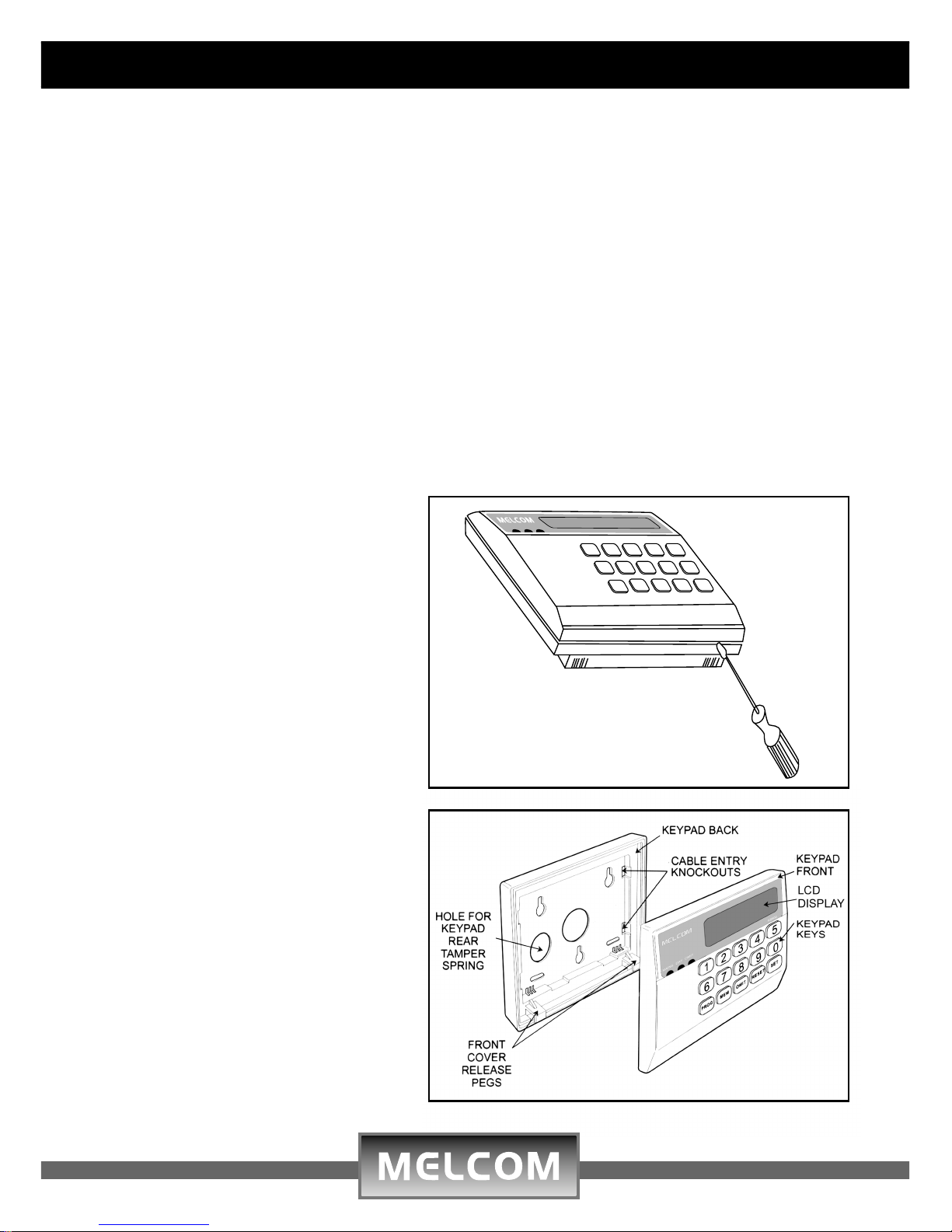
Mounting onto wall
Using the rear keypad plastic case
as a template, mark the positions
of the mounting holes. The
mounting surface must be solid, do
not mount onto a flammable or
uneven surface. Drill mounting
holes and fit wall plugs, before
drilling make sure you wear safety
goggles and check for hidden cable
and pipes.
K6600
43215
98760
PROG
MEN OMIT RESET SET
Opening the keypad
To remove the front cover, insert a
flat headed screwdriver to release
the pegs located at the bottom of
the keypad.
K6600 LCD Keypad Installation Instructions
Description
The K6600 LCD keypads can be connected to both the ST6100 & ST6600 control
panel. Up to a maximum of 6 Keypads can be connected to anyone control panel. The
keypad features, 32 segment LCD display, back light illumination, power, system status
and omit LED indication, onboard personal alarm (press: SET, OMIT, SET).
Installation instructions:
Handling the keypad
l Make sure your hands are clean
l Handle keypad carefully the LCD display is fragile
l Do not use unnecessary force when opening and closing the plastic case
l Peel off the protection film covering the LCD display
l Set the addressable configuration jumpers
l Install the keypad close to your entry/exit point of the building,
it should be positioned out of reach of children.
Page 2
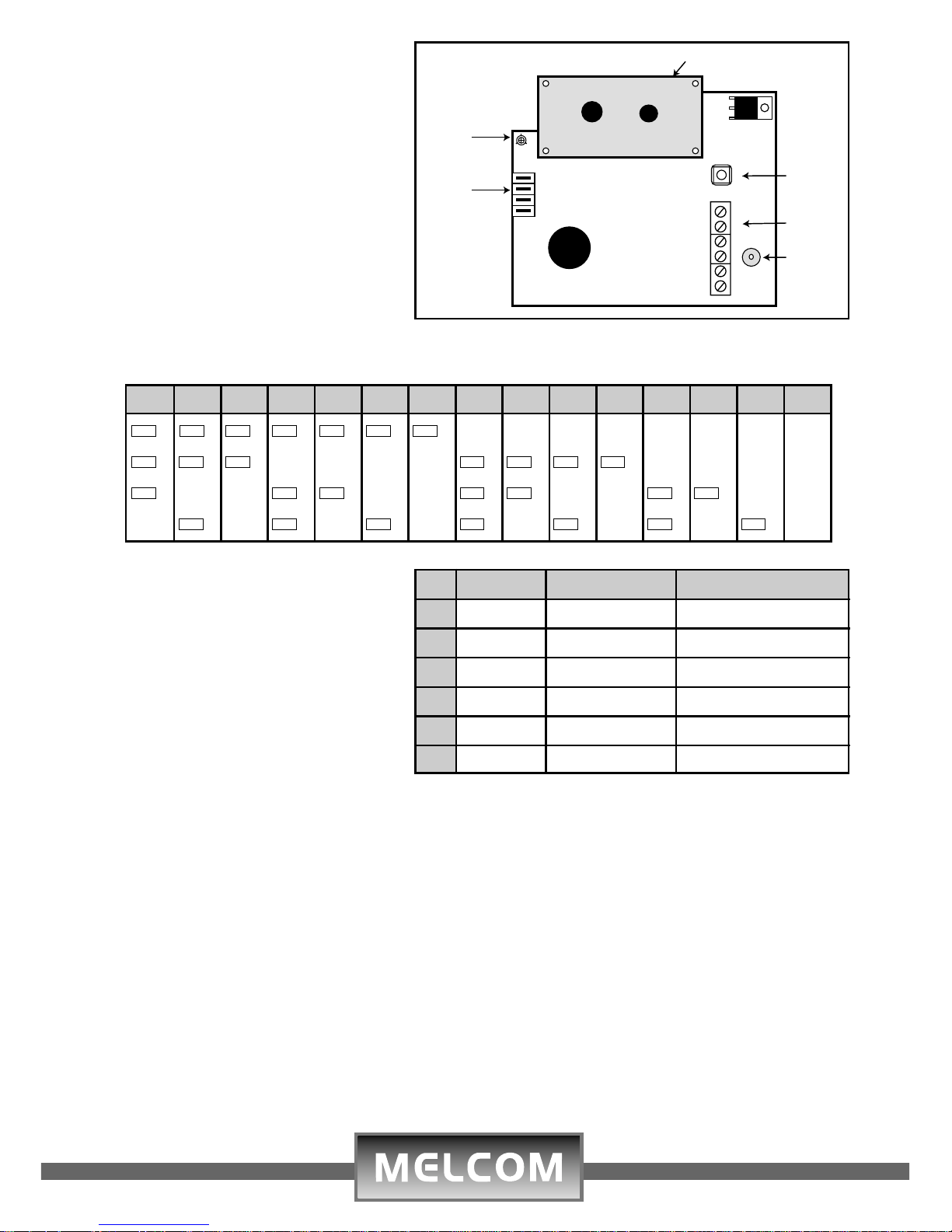
Address Table
Wiring Terminal Block
Thread 6 core cable through one
of the cable knockouts in the rear
plastic casing.
Wire according to the opposite
table.
Closing Keypad Cosing
To fit the front cover, align the
bottom pegs with their concentric
slots, and clip the top onto the
base, make sure all sides are
securely closed.
Operation
Refer to the ST6100/ST6600 installation and user manual
LCD
Tamper
Switch
Wiring
Terminal
Blocks
Buzzer
- + NETWORK M B
BLK RED YEL BLU GREWHT
1
2
3
4
5
6
8
4
2
1
LCD Contrast
Adjusting
Trimmer
Addressable
Pins
Contrast Adjustment
The LCD display screen contrast
can be adjusted by turning the
trimmer using a small screw
driver
Configuring Address Setting
Each keypad or accessory must
have a unique address when
connected to the control panel
bus. If invalid address set,
keypads will not work
Specifications
Operating Voltage: 12Vdc
Quiescent Current: LCD Backlight Off 16.7mA
Current: LCD Backlight Off 90mA
Current: in Alarm 70mA
Wiring: 6 core Multi-stranded cable
7x0.20m
2
Dimensions: 135mmx108mmx80mm
Housing Material: ABS Plastic
Weight: 0.30Kgs
123456789101112131415
O O 8 O O 8 O O 8 O O 8 O O 8 O O 8 O O
8
n
8
n
8
n
8
n
8
n
8
n
8
n
8
n
8
O O 4 O O 4 O O
4
n
4
n
4
n
4
n
4
O O 4 O O 4 O O 4 O O
4
n
4
n
4
n
4
n
4
O O
2
n
2
n
2
O O 2 O O
2
n
2
n
2
O O 2 O O
2
n
2
n
2
O O 2 O O
2
n
2
n
2
n
1
O O
1
n
1
O O
1
n
1
O O
1
n
1
O O
1
n
1
O O
1
n
1
O O
1
n
1
O O
1
n
1
No. Location Wire Colour Description
1 - BLK(Black) Negative
2 + RED(Red) 12 Volts Positive
3 Network YEL(Yellow) Data Out
4 Network BLU(Blue) Data in
5 M GRE(Green) Mains Indication
6 B WHT(White) Battery Indication
91-101-881
 Loading...