

Page 1
2004
SerSer
Ser
SerSer
vicevice
vice
vicevice
MITSUBISHI ELECTRIC
ManualManual
Manual
ManualManual
DIGITAL LIGHT PROCESSING™ PROJECTION TV
V26 CHASSIS
MODELS
V26 V26+ V26++
WD-52525 WD-52725 WD-52825
WD-62525 WD-62725 WD-62825
WD-52525
CAUTION:
Before servicing this chassis, it is important that the service person read the "SAFETY PRECAUTIONS" and
"PRODUCT SAFETY NOTICE" contained in this manual.
SPECIFICATIONS
• Power Input : AC 120V, 60Hz
• Power Usage : 275W
• Light Engine : DLP 0.85" 1280 x 720p
• Lamp : 120W VIP Type
• Channel Frequencies : Air - VHF 2 ~ 13 UHF 14 ~ 69
Analog Cable - 1 ~ 125
Digital Cable - 1 ~ 135
• Antenna Input : 2 RF 75Ω unbalanced
• Tuning : 1 NTSC/ATSC/QAM64&256
1 CableCARD™ Slot
1 NTSC for PIP
• Cabinet Dimensions : [WD-52xxx] 37.2" x 49.6" x 17.4"
[WD-62xxx] 43.7" x 58.3" x 19.9"
• Weight : [WD-52xxx] 132.4 lbs
[WD-62xxx] 165.5 lbs
• Speakers (10Wx2) : 5" Coaxial x 2
• Input Level : VIDEO IN JACK (RCA Type)
1.0Vp-p 75Ω unbalanced
AUDIO IN JACK (RCA Type)
-4.7dBm 43kΩ unbalanced
: S-VIDEO IN JACK
(Y/C separate type)
Y:1.0 Vp-p C:0.286Vp-p(BURST)
75Ω unbalanced, 480i
: COMP / Y, Pr, Pb (RCA Type )
Y: 1.0 Vp-p Pr, Pb: 700mVp-p, 480i,
480p, 720p, 1080i
: DTV / Y(G), Pr(R), Pb(B), H, V (RCA
Type) Y: 1.0 Vp-p Pr, Pb: 700mVp-p,
480i, H, V: 3.0Vp-p 75Ω, 480i,
480p, 720p, 1080i
: VGA / R,G,B,V,H (15 pin D) 640x480,
800x600, 1024x768, 720x1280,
60Hz
• Output Level : VIDEO OUT JACK (RCA Type)
1.0Vp-p 75Ω unbalanced
: AUDIO OUT JACK (RCA Type)
-4.7dBm 4.7kΩ unbalanced
• Digital : IEEE-1394 I/O Jacks
Interface : AC-3 Digital Audio Output (RCA
Type)
TM
: HDMI
: MonitorLink
: 4 Memory Card Reader Inputs
TM
Control/RS-232C
• Design specifications are subject to change without notice.
MITSUBISHI DIGITAL ELECTRONICS AMERICA, INC.
9351 Jeronimo Road, Irvine, CA 92618-1904
Copyright © 2004 Mitsubishi Digital Electronics America, Inc.
All Rights Reserved
Page 2

Page 3

MODEL: WD-52525 / WD-52725 / WD-52825 / WD-62525 / WD-62725 / WD-62825
CONTENTS
INTRODUCTION ................................................................................................................................5
PRODUCT SAFETY NOTICE ...........................................................................................................5
SAFETY PRECAUTIONS .................................................................................................................6
DISASSEMBLY PROCEDURES ......................................................................................................... 7
Cabinet Front Disassembly ............................................................................................................. 7
Cabinet Rear Disassembly .............................................................................................................. 9
ELECTRICAL CHASSIS REPLACEMENT ........................................................................................ 10
OPTICAL ENGINE REPLACEMENT ................................................................................................. 13
DATA COPY PROCEDURE ............................................................................................................... 16
DIAMONDSHIELD™ REPLACEMENT .............................................................................................. 17
SERVICING THE LENTICULAR SCREEN AND FRESNEL LENS ..................................................... 18
INITIAL SETUP ................................................................................................................................ 20
FRONT PANEL LED DIAGNOSTICS ................................................................................................ 22
SERVICE ADJUSTMENTS ............................................................................................................... 24
Equipment .................................................................................................................................... 24
Circuit Adjustment Mode ............................................................................................................... 24
Adjustment Items and Initial Data Settings ................................................................................... 26
Electrical Adjustments .................................................................................................................. 27
Mechanical Adjustments ............................................................................................................... 27
REPLACEMENT PARTS .................................................................................................................. 30
SCREEN ASSEMBLY PARTS .......................................................................................................... 33
CIRCUITRY BLOCK DIAGRAMS ..................................................................................................... 35
PCB INTERCONNECT DIAGRAM
Page 3
Page 4

MODEL: WD-52525 / WD-52725 / WD-52825 / WD-62525 / WD-62725 / WD-62825
Page 4
Page 5

MODEL: WD-52525 / WD-52725 / WD-52825 / WD-62525 / WD-62725 / WD-62825
INTRODUCTION
This service manual provides service instructions for PTV Models and Chassis:
V26 Chassis V26+ Chassis V26++ Chassis
WD-52525 WD-52725 WD-52825
WD-62525 WD-62725 WD-62825
This service manual includes:
1. Assembly and disassembly instructions for the front and rear cabinet components.
2. Servicing of the Lenticular Screen and Fresnel Lens.
3. Servicing down to major components, chassis, Optical Engine, Lamp Ballast, etc..
4. Electrical adjustments.
5. Optical Adjustments.
6. Chip parts replacement procedures.
7. Simplified circuit path diagrams.
8. Overall PCB interconnect block diagram.
The parts list section of this service manual includes:
1. Cabinet and screen parts.
2. Electrical parts.
Block diagrams of the above listed models are included in this service manual for better understanding of the circuitry.
PRODUCT SAFETY NOTICE
Many electrical and mechanical parts in television receivers have special safety related characteristics. These characteristics are often not evident from visual inspection nor can the protection afforded by them necessarily be obtained by
using replacement components rated for higher voltage, wattage, etc.
Replacement parts which have special safety characteristics are identified in this service manual.
Electrical components having such features are identified by shading on the schematic diagram and by bold type in
the parts list of this service manual. Therefore, the replacement for any safety part should be identical in value
and characteristics.
Digital Light Processing, Digital Micromirror Device and DLP are trademarks of Texas Instruments.
CableCARD is a trademark of Cable Television Laboratories, Inc.
HDMI, the HDMI logo and High-Definition Multimedia Interface are trademarks or registered trademarks of HDMI Licensing LLC.
Page 5
Page 6
MODEL: WD-52525 / WD-52725 / WD-52825 / WD-62525 / WD-62725 / WD-62825
SAFETY PRECAUTIONS
NOTICE: Observe all cautions and safety related notes located inside the receiver cabinet and on the
receiver chassis.
WARNING:
1. Operation of this receiver outside the cabinet or with the cover removed presents a shock hazard
from the receiver's power supplies. Work on the receiver should not be attempted by anyone who is
not thoroughly familiar with the precautions necessary when working on high voltage equipment.
2. When service is required, observe the original lead dress. Extra precaution should be taken to
assure correct lead dress in the high voltage area. Where a short-circuit has occurred, replace those
components that indicate evidence of overheating.
WARNING ... RISK OF EYE INJURY
Do not look into the light source, lens or mirror when operating the TV.
Leakage current check:
Before returning the receiver to the customer, it is recommended that leakage current be measured according to the
following methods.
1. Cold Check
With the alternating current (AC) plug removed from the AC source, place a jumper across the two AC plug
prongs. Connect one lead of an ohm meter to the AC plug and touch the other lead to each exposed metal part
(i.e. antennas, handle bracket, metal cabinet, screw heads, metal overlay, control shafts, etc.), particularly any
exposed metal part that has a return path to the chassis. The resistance of the exposed metal parts having a
return path to the chassis should be a minimum of 1Mega Ohm. Any resistance below this value indicates an
abnormal condition and requires corrective action.
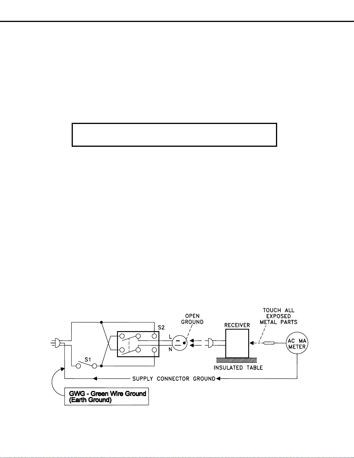
2. Hot Check ...Use the circuit shown below to perform the hot check test.
1. Keep switch S1 open and connect the receiver to the measuring circuit. Immediately after
connection, and with the switching devices of the receiver in their operating positions, measure the
leakage current for both positions of switch S2.
2. Close switch S1, energizing the receiver. Immediately after closing switch S1, and with the
switching devices of the receiver in their operating positions, measure the leakage current for both
positions of switch S2. Repeat the current measurements of items 1 and 2 after the receiver has
reached thermal stabilization. The leakage current must not exceed 0.5 milliampere (mA).
Page 6
Page 7
MODEL: WD-52525 / WD-52725 / WD-52825 / WD-62525 / WD-62725 / WD-62825
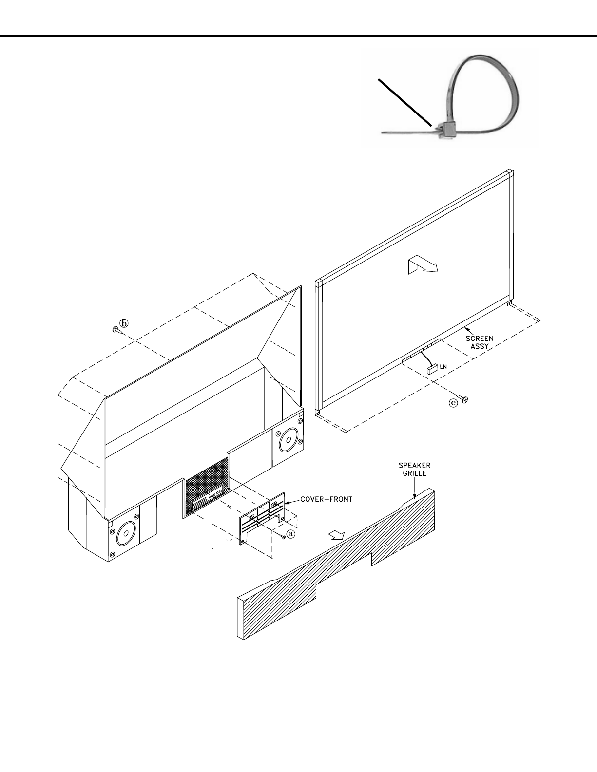
Reusable Wire Ties
Do not cut wire ties during disassembly, reusable
wire ties are used in these models. Lift the tab to release the wire tie. During reassembly, re-use wire ties to
ensure all wiring harnesses are properly bundled and
dressed.
CABINET DISASSEMBLY (FRONT VIEW)
WD-52525 / WD-62525 / WD-52725 / WD-62725
*Refer to the Parts List for Part Numbers
Lift Tab to Release
Wire Tie
Front Cabinet Disassembly
1. Remove the SPEAKER-GRILLE by pulling forward.
2. Remove screws (a) to remove the COVER-FRONT.
3. Remove screws (b) on the rear of the upper back cover (4 across the top and 3 on each side).
4. Remove the 4 screws (c) holding the bottom of the Screen Assembly.
5. Unplug connector LN from the Control Panel.
6. Lift the Screen Assembly up slightly then pull towards the front to remove the assembly.
Page 7
Page 8
MODEL: WD-52525 / WD-52725 / WD-52825 / WD-62525 / WD-62725 / WD-62825
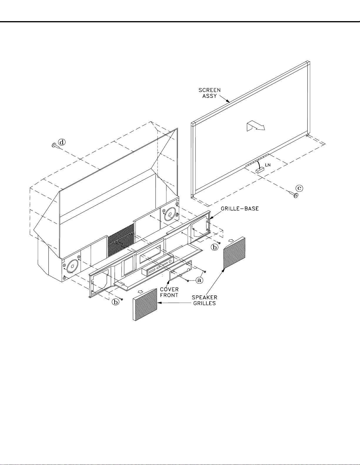
CABINET DISASSEMBLY (FRONT VIEW)
WD-52825 /WD-62825
*Refer to the Parts List for Part Numbers
Front Cabinet Disassembly
1. Remove the SPEAKER-GRILLES by pulling forward.
2. Remove screws (a) to remove the COVER-FRONT.
3. Remove screws (b) to remove the GRILLE-BASE.
4. Remove screws (d) on the rear of the upper back cover (3 on each side and 4 across the top).
5. Remove the 4 screws (c) holding the bottom of the Screen Assembly.
6. Unplug connector LN from the Control Panel.
7. Lift the Screen Assembly up slightly then pull towards the front to remove the assembly
8. To disconnect the Card Reader and the Front Inputs:
• Unplug the Card Reader USB connector from the PCB-DM.
• Unplug the Front 1394 cable from the HDD Module (Hard Drive).
• Unplug the CC connector from the Front Inputs.
Page 8
Page 9
MODEL: WD-52525 / WD-52725 / WD-52825 / WD-62525 / WD-62725 / WD-62825
(b)
(b)
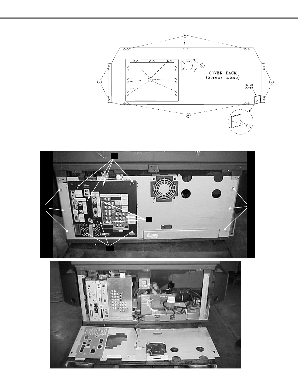
CABINET DISASSEMBLY (REAR VIEW)
FILTER-COVER Removal
Remove 2 screws (d) to remove the Filter Cover.
COVER-BACK Removal
1) Remove 9 screws (a)
2) Remove 5 screws (b)
3) Remove 2 screws (c)
4) Pull the COVER-BACK
from the cabinet.
Rear Plate Removal
1) Remove 6 screws (a)
2 Remove10 screws (b)
3) Pull the Rear Plate from the
cabinet.
NOTE: To operate set, the Filter Cover must be re-installed after the Cover-Back and Rear Plate have been removed and the
Exhaust Fan must be connected.
(a)
(a)
(b)
(b)
(b)
(a)
(a)
Page 9
Page 10
MODEL: WD-52525 / WD-52725 / WD-52825 / WD-62525 / WD-62725 / WD-62825
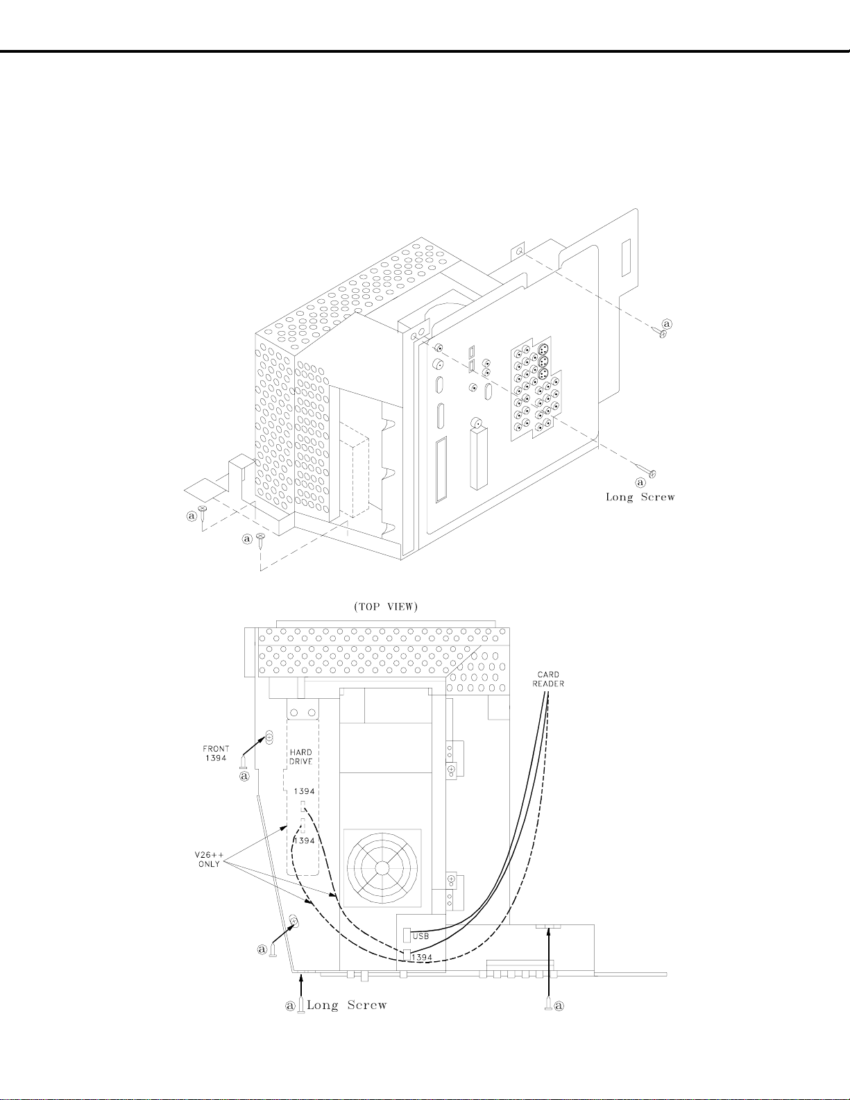
ELECTRICAL CHASSIS REPLACEMENT
1) Remove the 4 black screws (a) securing the chassis shown in the two diagrams below.
2) Unplug the USB and 1394 connectors from the Card Reader.
NOTE: In the V26++ chassis the Card Reader 1394 connector plug into the Hard Drive Module.
3) Disconnect all cables to the front of the cabinet, the Optical Engine and the Lamp Ballast (see next page).
4) Carefully slide the chassis from the cabinet.
5) IMPORTANT: After Electrical Chassis replacement, perform the Data Copy Procedure (page 16).
Page 10
Page 11

MODEL: WD-52525 / WD-52725 / WD-52825 / WD-62525 / WD-62725 / WD-62825
NOTE: To remove the chassis, the two connectors to the Lamp Ballast must be
disconnected at the Lamp Ballast.
Accessing & Disconnecting The Lamp Ballast
Removing the Right Support
Remove the 3 screws shown below.
3 Screws
Removing the Lamp Ballast Shield
(4 screws)
4 Screws
Unplug CN1 & CN2
Connectors
Unplug
Connectors
Page 11
Page 12
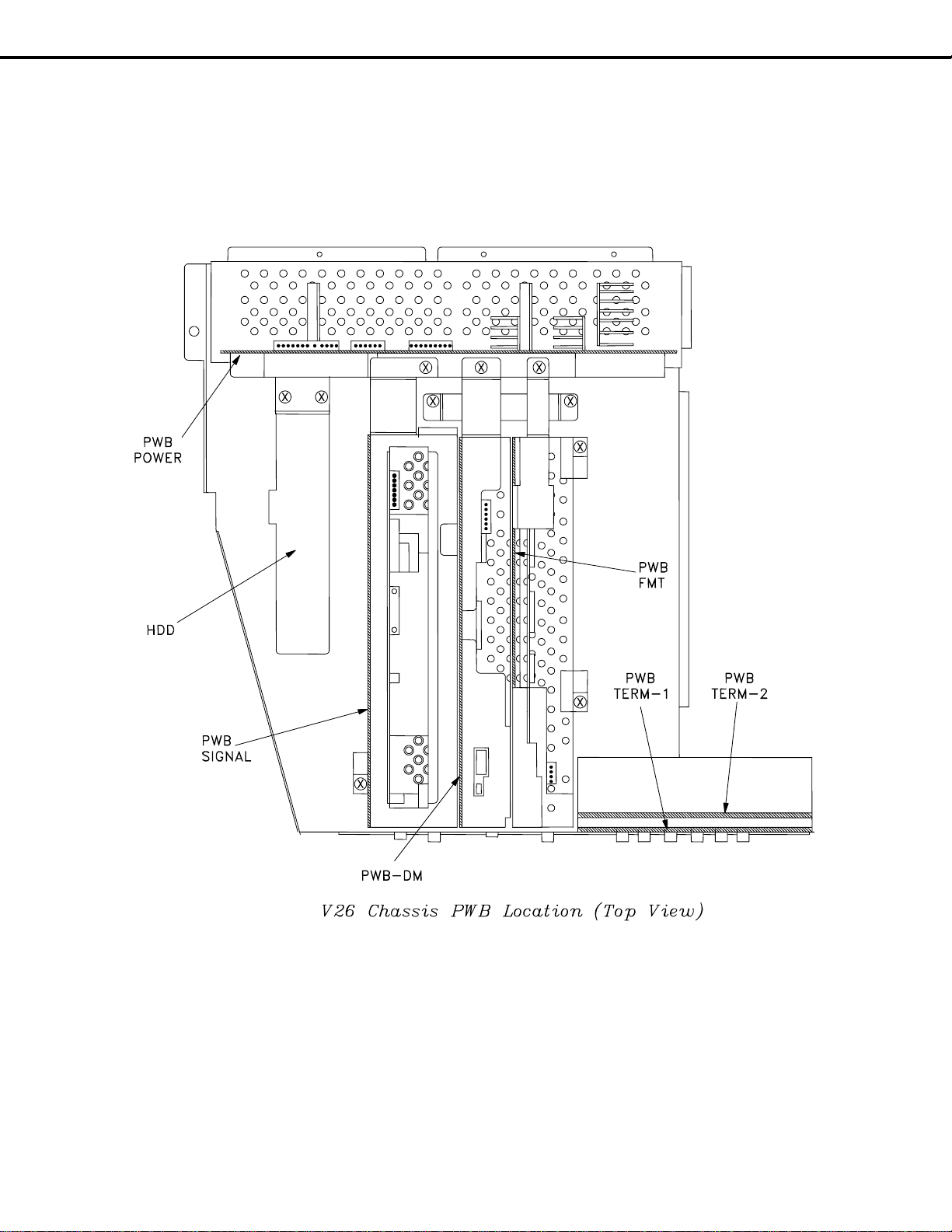
MODEL: WD-52525 / WD-52725 / WD-52825 / WD-62525 / WD-62725 / WD-62825
V26 Chassis PWB Locations
NOTE: The Hard Drive is only in the V26++ models.
Page 12
Page 13
MODEL: WD-52525 / WD-52725 / WD-52825 / WD-62525 / WD-62725 / WD-62825
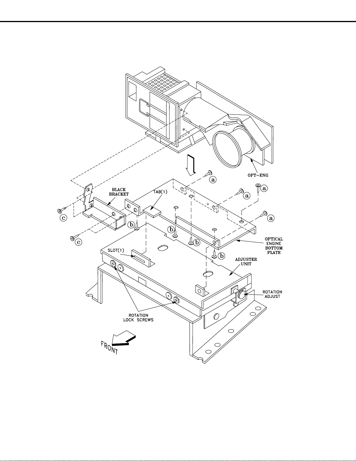
Optical Engine Mounting
Optical Engine Replacement
The Optical Engine is mounted on the Adjuster assembly as shown in the above diagram.
1) Four screws (a) secure the bottom plate and Optical Engine to the Adjuster assembly.
2) The bottom plate tab (1) slides into slot (1) on the Adjuster.
3) The Optical Engine is secured to the bottom plate by 4 screws (b).
4) The Black Bracket is secured to the bottom plate and the Lamp Box with 4 screws (c).
5) To replace the Optical Engine, the Optical Engine, bottom plate and black bracket need to be removed
together as an assembly. Refer to the following pages for exact replacement instructions.
Page 13
Page 14
MODEL: WD-52525 / WD-52725 / WD-52825 / WD-62525 / WD-62725 / WD-62825
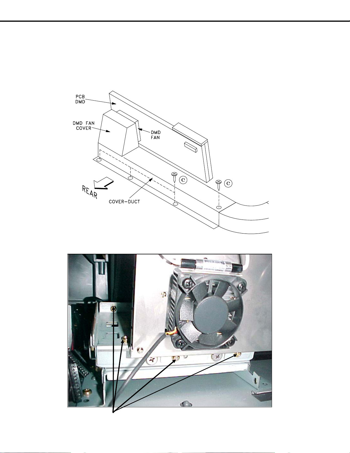
Removing the Optical Engine
1) Remove the Cabinet Back (refer to disassembly instructions).
2) Disconnect all connectors from the Optical Engine, Lamp Cartridge Housing and the PCB-DMD.
3) From the rear of the TV, remove the 4 screws (c), to remove the COVER-DUCT and DMD Fan cover.
4) From the rear of the TV, remove the 4 brass colored screws (a), shown below, securing the bottom plate to
the Adjuster assembly.
5) Slide the Optical Engine/Lamp Cartridge Housing towards the rear to remove from the TV.
(a)
O ptic al Engine ( Re a r Vie w / Aird uct & DMD Fa n Cover Re moved)
Page 14
Page 15

MODEL: WD-52525 / WD-52725 / WD-52825 / WD-62525 / WD-62725 / WD-62825
Remove the following parts from the Optical Engine
• DMD Heat Sensor
• The Optical Engine bottom plate and black bracket
DMD Heat Sensor Removal (Figure 1)
1) Remove screw (a) on the top of the DMD Fan.
2) Set the Heat Sensor aside to install on the replacement Optical Engine.
(a)
Figure 1: DMD Heat Sensor
Bottom Plate & Black Bracket Removal
1) Remove the 4 screws (B) from the Bottom Plate (Figure 2)
2) Remove the two screws (C), holding the Black Bracket to the Lamp Box. (Figure 3)
Heat Sensor
(B)
Bottom V iew
Figure 2: Bottom Plate
Page 15
Bottom Pla te
Page 16

MODEL: WD-52525 / WD-52725 / WD-52825 / WD-62525 / WD-62725 / WD-62825
Bla ck Bra cke t
(C)
Front View
Figure 3: Black Support Bracket
Installing the Optical Engine
1) Install the Bottom Plate, Black Support Bracket and the Heat Sensor, removed from the original Optical
Engine, on the replacement Engine
2) Reverse the removal procedure to install the replacement Optical Engine in the cabinet.
3) The following adjustments may have to be performed after the installation. (See Service Manual)
• Horizontal and Vertical Electrical Centering Adjustment.
• Optical Unit Rotation Adjustment
• Optical Unit Keystone Distortion Adjustments.
4) IMPORTANT: After Optical Engine replacement, perform the Data Copy Procedure described below.
Data Copy Procedure
This procedure must be performed after replacing either the Electrical Chassis or Optical Engine.
1) To display the data copy menu press <TV MENU> <2-4-5-7> <0>
2) Use the cursor keys to yellow highlight “Copy Light Engine EEPROM to DM”
3) Press <ENTer>
4) After the copy procedure has been completed, exit the menu by pressing <HOME>
Copy Light Engine EEPROM to DM
Restore backup
UPLOAD TERMINAL BOARD DATA
Page 16
Page 17

MODEL: WD-52525 / WD-52725 / WD-52825 / WD-62525 / WD-62725 / WD-62825
DIAMOND SHIELD REPLACEMENT
To Remove the Diamond Shield:
1. While wearing soft cotton gloves, loosen the
sides of the Diamond Shield by pressing a small
plastic card (the size of a standard credit card or a
clean, plastic, putty knife) into the middle of the
side slot. The Diamond Shield side will snap out
of the top middle and bottom clips. Loosen both
sides before proceeding to step 2.
2. After the sides are free, gently push down on the
top of the Diamond Shield. It will slide out of the
top channel.
3 Carefully pull the screen up to remove it from the
bottom channel. Store the Diamond Shield in a clean,
dust free area, where it will not be scratched.
To Install the Diamond Shield:
4. Slide the Diamond Shield into the bottom channel,
making sure it fits securely.
5. Press gently on the top of the Diamond Shield to
slightly bow the screen towards you. Insert the
top of the Diamond Shield into the top channel. It
should fit securely.
6. At each side, gently press the top, middle and
bottom of the Diamond Shield to snap it back into
place.
2
1
1
1
3
5
6
6
6
1
1
1
6
6
6
WARNING
Sharp edges! Always wear gloves to
handle, lift, install and remove the
Diamond Shield.
4
Page 17
Page 18

MODEL: WD-52525 / WD-52725 / WD-52825 / WD-62525 / WD-62725 / WD-62825
SERVICING THE LENTICULAR SCREEN AND FRESNEL LENS
CAUTION: Wear gloves when handling the Lenticular Screen and Fresnel Lens.
This prevents cuts and finger prints. Do not place Fresnel Lens in the sun.
This may cause fire and heat related injuries.
Lenticular Screen and Fresnel Lens Removal
1. Remove the screen assembly shown in the Cabinet Disassembly procedure.
2. Remove the four screws (a) to remove the bottom of the SCREEN-FRAME-BOTTOM .
3. Carefully slide the Lenticular Screen and Fresnel Lens combination from the Screen Frame assembly.
Note: When separating the Lenticular Screen from the Fresnel Lens, use caution
while prying the Screen and Lens apart. Use a slot type screw driver, and
remove the pressure sensitive double sided tape.
Page 18
Page 19

MODEL: WD-52525 / WD-52725 / WD-52825 / WD-62525 / WD-62725 / WD-62825
SERVICING THE LENTICULAR SCREEN AND FRESNEL LENS
Lenticular Screen and Fresnel Lens Installation
Note: Store the Lenticular Screen and Fresnel Lens in a cool dry place. High heat and humidity may
deform the Lenticular Screen and Fresnel Lens.
1. Apply double coated tape (Part #LENS-TAPE) along the top rear edge of the Lenticular Screen, as shown
below. Refer to the table below for the tape length.
2. Place the Fresnel Lens on top of the Lenticular Screen and apply pressure at the top edge
to bond them together.
3. Reverse the Screen Removal procedure to insert the screens in the Screen Frame Assembly.
*X INCHES - Refer to the Tape Length in the table below
MODEL SCREEN SIZE TAPE LENGTH
WD-52525 52 Inches 46.3 Inches
WD-52725 " "
WD-52825 " "
WD-62525 62 Inches 55.1 Inches
WD-62725 " "
WD-62825 " "
Page 19
Page 20

MODEL: WD-52525 / WD-52725 / WD-52825 / WD-62525 / WD-62725 / WD-62825
A
V
INITIAL SETUP
OPTION MENU
1. Press the “MENU” button on the remote hand unit.
2. Press the buttons “2”, “4”, “7” and “0” in order.
(The screen will change to the option menu.)
OPTION MENU <TV MENU> <2-4-7-0>
Initialize
Power Restore: Off
DTV Port: AUTO
Direct Key Mode: Off
NetCommand Software: N/
Digital Signal Strength:
26 XXX.XX
00000 00000 00000 00000 00000
Total TV
On Time
Current
Lamp
Time
Previous
Lamp
Time
Previous
Lamp
Time 2
Initial Main Menu D efaults
Setup Menu
Language English Programs Not Rated Enable
Combine Channel View -- Movie Rating PG
NetCommand Menu
Edit -- Start 12:00pm
Transport Menu On S top 12:00pm
Default Digital Record Device -Icon Order -- Lock by Time On
Antenna Menu
Antenna 1 Unlock Time 12:00pm
Memorize -- Front B utton Lock Off
Prefer Digital -Channel 3 A/V Memory Res et Ant-1
Memory A dded Settings
Name -SQV -- Bass 50%
Time Me nu
Clock Setting Manual Balanc e 50%
Time 12:00pm Surround Off
Date -- Listen to (Analog Only) Stereo
Time Zone -- Level Sound (Analog Only) On
Daylight Savings Time -- Language (Digital Only) English
Tim er --
Captions Menu
Analog Captions On if Mute Brightness 50%
Background Gray Sharpness 50%
Digital Caption On if Mute Color 50%
Appearance Default Tint 50%
Digital S ettings Color Temp High
Font Font 3 Video Noise Standard
Siz e Large Film Mode (Auto) On
Color White Define Edge On
Background Black Color Balanc e
Opacity Translucent Video M ute On
Background Opacity Translucent black Enhancem ent On
V-Chip Lock Menu
V-Chip Off
TV Rat i n g TV -P G
FV-Fantas y Violence Enable
D-Sexual Dialog Enable
L-Adult Language Enable
S-Sexual Situations Enable
Page 20
V-Violence Enable
V-Chip Time
Lock by Time
Lock Time 12:00pm
Audio/Video
Audio
Treble 50%
Video
Contrast 100%
TV Speakers On
TV Volume
PIP Source
PIP Position
POP Position
PIP/POP Format
Format
30%
Ant 1 003
Lower Right
Right Half
Double W indow
Stretch
Previous
Lamp
Time 3
Page 21

MODEL: WD-52525 / WD-52725 / WD-52825 / WD-62525 / WD-62725 / WD-62825
A/V RESET DEFAULT SETTINGS (By Input)
A/V Memory Ant 1/2
INPUTS
1/2/3
Component
1/2/DTV
1394 when
connected
HDMI Card 1~4
Contrast Max. Max. Max. Max. Max. Max.
Brightness Center Center Center Center Center Center
Sharpness Center Center Center Center Center Center
Color Center Center Center Center Center Center
Tint Center Center Center Center Center Center
Color Temp. High High High High High High
Video Noise Standard Standard Standard N/A Standard N/A
TV Film Mode (Auto) On On On N/A On N/A
TV DefinEdge VSM On On On On On On
Bass Center Center Center Center Center Center
Treble Center Center Center Center Center Center
Balance Center Center Center Center Center Center
Surround OFF OFF OFF OFF OFF OFF
Listen To Stereo N/A N/A N/A N/A N/A
Level Sound OFF OFF OFF OFF OFF OFF
A. A/V Memory
Each of the external inputs has its own Audio/Video Memory. A change in an A/V setting at a specific input is
stored in memory for that specific input.
B. A/V Reset
The AV Memory Reset in the user’s menu initializes the selected input’s A/V Memory.
Remote Control Operational Modes
There are two Remote Hand Unit Operational Modes, “Standard” and “NetCommand™”. The Remote is initially
in the “Standard” mode. The “NetCommand” mode is used when controlling Home Theater devices using
NetCommand. To change the Remote Operational Mode:
• Set the Remote to the TV Layer
• Point the Remote away from the TV.
• To change to “Netcommand” ... Hold the “Power” button and press “9-3-5” in sequence.
• To change to “Standard” ... Hold the “Power” button and press “0-0-0” in sequence.
Page 21
Page 22

MODEL: WD-52525 / WD-52725 / WD-52825 / WD-62525 / WD-62725 / WD-62825
FRONT LED INDICATOR DIAGNOSTICS
The front panel LEDs provide an indication of the sets operation, and the possible cause of a malfunction. There
are three front panel LEDs, “Power”, “Status” and “Lamp”. Which LED is lit, the color, and whether it is blinking or
steady indicate the current status, or a possible malfunction.
Normal LED Indications
POWER
LED
Off Off Off Stby Off
Green Off Off P-0N Power On
Off Off
Blinks
Green
Slow Blinks
Green
STATUS
LED
LAMP
LED
Blinks
Green
Power
Status
After Turn
Off
Condition
Lamp Fan On for 1 minute
Off Off Stby Booting after AC applied
Off Off Stby On Timer is set
Abnormal LED Indications
POWER
LED
Off Yellow Off
Off or On Off Yellow
Off Off
Off
Off Off Red Stby Lamp did not turn On
Off
Off
Off
Off Red Off "
STATUS
LED
Blinks
Yellow
*Blinks
Red
**Blinks
Red
***Blinks
Red
*Blinks = (1 long/1 short)
**Blinks = (1 long/2 short)
***Blinks = (1 long/3 short)
LAMP
LED
Blinks
Yellow
Off " Filter Cover Open
Off
Off "
Off " DMD or Lamp Fan Stopped
Power
Status
Low
Power
No
change
Low
Power
Low
Power
Condition
Excess Temperature
Usage time over 4000 Hrs.
Lamp Cover open
Chassis Fan Stopped
Ballast or Exhaust Fan
Stopped
Short or DVI Cable from FMT
to DMD disconnected
Page 22
Page 23

MODEL: WD-52525 / WD-52725 / WD-52825 / WD-62525 / WD-62725 / WD-62825
3. Error Code Operational Check
Note: The TV must be in “Shut Down” and not manually switched Off, to perform the Error Code Opera-
tional Check. When the TV is switched Off, the code automatically resets to “12” No Error.
Press the front panel “DEVICE” and “MENU” buttons at the same time, and hold for 5 seconds to
activate the Error Code Operational Check. The LED will then flash denoting a two digit Code.
Note: The front panel buttons must be used, NOT those on the Remote Control.
• The number of flashes indicates the value of the MSD (tens digit) of the Error Code.
• The flashing then pauses for approximately 1/2 second.
• The LED then flashes indicating the value of the LSD (ones digit) of the Error Code.
Example: If the Error Code is “32”, the LED will flash three times, pause, and then flash two times.
• The Error Code is repeated a total of 5 times.
4. Error Codes
The Error Code designations are listed below:
ERROR CODES
Press and Hold "DEVICE" and "MENU" FOR 5 SECONDS
Error Code Probable Cause
12 No error detected
22 Rec overy from momentary Reset
32 Lam p Cover open
33 A ir Filter Cover open
34 Lam p abnormality
35 Chas sis Fan failure
36 E xhaust (Bac k Cover) or Lamp Ballast Fan failure
37 E ngine (DMD or Lamp) Fan failure
38 E xcess Lamp Temperature
39 E xcess DMD Temperature
41 S hort Detec ted
44 DV I Cable (between Chassis and Engine) disconnected
Page 23
Page 24

MODEL: WD-52525 / WD-52725 / WD-52825 / WD-62525 / WD-62725 / WD-62825
SERVICE ADJUSTMENTS
There are only 5 Service Adjustments required:
Two Electrical Adjustments
• Horizontal Centering
• Vertical Centering
Three Mechanical Adjustments
• Picture Rotation
• Horizontal Keystone Distortion
• Vertical Keystone Distortion
Tools, Test equipment and Test signals
• Conventional Hand Tools.
• No additional Test Equipment is required.
• Test Signals are internally generated, no external signals are required.
Circuit Adjustment Mode
On these models, the Circuit Adjustment Mode is used only for:
• Test Signal activation
• Horizontal Centering
• Vertical Centering
1. Activating the Circuit Adjustment mode
1. Press the “TV MENU” button on the remote control.
(The Customer Menu will appear.)
2. Press the buttons “2”, “4”, “5” and “7” in that order.
(The screen will change to the adjustment mode.)
If unsucessful, repeat steps 1 and 2.
2. Test Signal Activation
When in the Circuit Adjustment mode, press “REWIND” once on the remote control to activate the test pattern.
This pattern is used for both electrical and mechanical adjustments.
Page 24
Page 25

MODEL: WD-52525 / WD-52725 / WD-52825 / WD-62525 / WD-62725 / WD-62825
3. Adjustment Function Selection
Use the “AUDIO” button to select a specific Adjustment Function.
AD9883A MMTX
Functions
SMTXlight engfmt
4. Adjusting Data
After selecting an adjustment item, use the UP and DOWN cursor buttons to change adjustment data.
• If the UP button is pressed, the adjustment data increases.
• If the DOWN button is pressed, the adjustment data decreases.
5. Saving data
Press “ENTER” to save the adjustment data in memory.
The display characters go red for about one second in this step.
Note: If the circuit adjustment mode is terminated without pressing
“ENTER”, changes in adjustment data are not saved.
6. Terminating the circuit adjustment mode
Press the “HOME button or the “MENU” button twice on the remote to terminate the adjustment mode.
Note: The adjustment mode can be also terminated by turning the
power off.
Resetting Data to Factory Values
1) Enter the Service Adjustment Mode ... Press “TV MENU” “2-4-5-7”
2) Press “0” when in the Service Mode ... Three choices appear at the top of the screen.
"TV MENU" "2-4-7-0" then "0"
Copy Light Engine EEPROM to DM
Restore backup
UPLOAD TERMINAL BOARD DATA
3) Use UP & DOWN keys to highlight the desired choice, then Press “ENTER”
• Copy Light Engine EEPROM to DM ... required after replacing the Light Engine or Electrical
Chassis.
• Restore Back Up ... resets Service Mode data back to factory values. Use this feature if service
adjustment data has been corrupted or improper adjustments have been performed.
• Up Load Terminal Board Data ... uploads White Balance data from PWB-SIGNAL.
(Do Not Select. This option is for depot level service only.)
Page 25
Page 26

MODEL: WD-52525 / WD-52725 / WD-52825 / WD-62525 / WD-62725 / WD-62825
A
g
g
SERVICE MODE - Adjustment Items and Initial Data Values
AD9883
Item # Abbrev. Description
12 ROFF Red Offset 0~127
14 BOFF Blue Offset 0~127
Main Matrix (MMTX)
Item # Abbre v. Description
1 TNTM Hue Control 0~63 31
4 COLM Color Gain Control 0~63 19
15 YDRM Y Drive Gain Control 0~31 5
19 VPDM V Signal Pedestal Control 0~15 2
20 UPDM U Signal Pedestal Control 0~15 2
Data
Ran
Data
Range
e
Initial
Data
Sub M a trix (S MTX)
Item # Abbre v. Description
1 TNTS Hue Control 0~63 31
4 COLS Color Gain Control 0~63 16
15 YDRS Y Drive Gain Control 0~31 5
19 VPDS V S ignal Pedestal Control 0~15 2
20 UPDS U Signal Pedes tal Control 0~ 15 2
Light Engine (light eng)
Item # Abbrev. Description
120 GGH Temp. H Green Gain
121 GRH Temp. H Red Gain
122 GBH Temp. H Blue Gain
123 GGM Temp. M Green Gain
124 GRM Temp. M Red Gain
125 GBM Temp. M Blue Gain
126 GGL Temp. L Green Gain
127 GRL Temp. L Red Gain
128 GBL Temp. L Blue Gain
Data
Range
Initial
Data
Format (fmt)
Item # Abbrev. Description
Data
Ran
e
1 HPOS Horizontal Position 0~255
2 VPOS Vertical Position *0~255
* Do Not
set VPOS Data to 0 or 255 and press Enter.
(Video will be muted and On Screen Menus will no
longer be visible.)
Page 26
Page 27

MODEL: WD-52525 / WD-52725 / WD-52825 / WD-62525 / WD-62725 / WD-62825
Electrical Adjustments
[PICTURE POSITION]
1. Horizontal/Vertical Position
Measuring
Instrument
Test Point
Ext. Trigger
Measuring
Range
Input Signal
Input
----
----
------
-------
None
ANT-DTV
Purpose:
Symptom:
To center picture on the screen.
Picture is off center.
NOTE: The TV should be placed on a flat level surface.
Improper installation can affect raster geometry.
1. Select the ANT-DTV Input, no signal.
2. Press “TV MENU-2-4-5-7” in sequence
3. Press “REWIND” to activate the Test Pattern shown above.
4. Press “AUDIO” to select “FMT” function.
5. Use the “VIDEO” button to select “1 HPOS”.
6. Use the “ADJUST” buttons to center the picture Horizontally.
7. Press “ENTER” to save the adjustment.
8. Use the “VIDEO” button to select “2 VPOS”.
9. Use the “ADJUST” buttons to center the picture Vertically.
10. Press “ENTER” to save the adjustment.
CAUTION: DO NOT set VPOS data to “0” or “255” and press ENTER.
Video will be muted and On Screen Menus will no longer be visible.
11. Press “HOME” or “TV MENU” twice to terminate the Adjustment Mode.
Mechanical Adjustments
Picture Rotation Adjustment
NOTE: The TV should be placed on a flat level surface.
Improper installation can affect raster geometry.
1. Refer to the Disassembly Preocedures on Pages 7, 8, and 9 to remove the Speaker Grille, Front Cover, Back Cover and
Inner Cover.
2. From the front of the TV, lift the sponge to access and slightly loosen the brass Rotation Locking Screws on the Adjuster
Assembly, Figure 4A. (Use a 10mm wrench.)
3. From the rear of the TV, access the black Rotation Adjustment screw (4mm allen wrench) and adjust so the test pattern
center lines are parallel to the sides, top and bottom of the screen frame, Figure 4B. (Use a mirror to view the picture
from the rear of the set.)
4. Tighten the two Locking Screws. Use Locktite to secure the Adjustment Screw. (If necessary, use the electrical
adjustments to center the picture)
Page 27
Page 28

MODEL: WD-52525 / WD-52725 / WD-52825 / WD-62525 / WD-62725 /WD-62825
Page 28
Page 29

MODEL: WD-52525 / WD-52725 / WD-52825 / WD-62525 / WD-62725 / WD-62825
A
A
Keystone Adjustment
NOTE: The TV should be placed on a flat level surface.
Improper installation can affect raster geometry.
Horizontal Keystone Distortion
Vertical Keystone Distortion
1. From the front of the TV, loosen the two Keystone Locking Screws in the small mirror assembly. (10mm box wrench)
2. From the front of the TV, adjust the Horizontal Keystone Adjustment for minimum distortion. (4mm allen wrench)
3. From the front of the TV, adjust the Vertical Keystone Adjustment for minimum distortion.
Note: There may be some inter-action between the Keystone and Rotation Adjustments.
4. Tighten the Keystone Lock Screws. and secure the adjustment screws with Locktite.
Horiz
Keystone
djust
Locking Screws
Vertical
Keystone
djust
Small Mirror Assembly (Front View)
Page 29
Page 30

MODEL: WD-52525 / WD-52725 / WD-52825 / WD-62525 / WD-62725 / WD-62825
REPLACEMENT PARTS
Critical Electrical Components are indicated by Bold Type in the Parts List.
QUICK REFERENCE FOR COMMON REPLACEMENT PARTS
Customer Replaceable Parts
Part Name Description WD-52525 WD-62525 WD-52725 WD-62725 WD-52825 WD-62825
Lamp Cartridge LAMP - CARTRIDGE 915P020010 915P020010 915P020010 915P020010 915P020010 915P020010
Dust Filter FILTER - DUST 620D144010 620D144010 620D144010 620D144010 620D144010 620D144010
Remote Control REMOTE 290P123010 290P123010 290P123020 290P123020 290P123020 290P123020
Service Parts
Part Name Description WD-52525 WD-62525 WD-52725 WD-62725 WD-52825 WD-62825
Optical Engine OPTICAL-ENGINE 939P977010 939P977020 939P977010 939P977020 939P977010 939P977020
Electrical Chassis (Complete) ASSY-CHASSIS 955B298001 955B298001 955B298002 955B298002 955B298003 955B298003
Lamp Ballast PCB UNIT-POWER-LAMP
Memory Card PCB MEMORY-CARD-READER-PWB 299P271010 299P271010 299P271010 299P271010 299P271010 299P271010
Preamp PCB ASSY-PWB-PREAMP 935D774001 935D774001 935D774001 935D774001 935D774001 935D774001
Front PCB ASSY-PWB-FRONT 935D775001 935D775001 935D775001 935D775001 935D779001 935D779001
Control PCB ASSY-PWB-CONTROL 935D776001 935D776001 935D776001 935D776001 935D776001 935D776001
Right Speaker PCB ASSY-PWB-SPEAKER-R 935D806001 935D806001 935D806001 935D806001 935D806001 935D806001
Left Speaker PCB ASSY-PWB-SPEAKER-L 935D807001 935D807001 935D807001 935D807001 935D807001 935D807001
Hard Disk Drive ASSY-HDD-UNIT ----939P989010939P989010
Lamp Ballast Fan FAN-BALLAST 299P278020 299P278020 299P278020 299P278020 299P278020 299P278020
Lamp Fan FAN-LAMP 299P282010 299P282010 299P282010 299P282010 299P282010 299P282010
DMD Fan FAN-DMD 299P283010 299P283010 299P283010 299P283010 299P283010 299P283010
Chassis Fan FAN-COOLING 299P103050 299P103050 299P103050 299P103050 299P103050 299P103050
Exhaust Fan FAN-COOLING
Lamp Cover Detect Switch SW -MICRO 436P021010 436P021010 436P021010 436P021010 436P021010 436P021010
Filter Cover Detect Switch SW-MICRO 436P021010 436P021010 436P021010 436P021010 436P021010 436P021010
DMD Thermal Sensor SENSOR – THERMAL 299P280010 299P280010 299P280010 299P280010 299P280010 299P280010
Bold Type = Safety Critical
939P978010 939P978010 939P978010 939P978010 939P978010 939P978010
299P103050 299P103050 299P103050 299P103050 299P103050 299P103050
Screen Parts
Part Name Description WD-52525 WD-62525 WD-52725 WD-62725 WD-52825 WD-62825
DiamondShield
Lenticular Screen LENS - LENTICULAR 491P178020 491P174020 491P178020 491P176020 491P178020 491P176020
Fresnel Lens
DIAMOND - SHIELD
LENS - FRESNEL 491P177020 491P173020 491P177020 491P175020 491P177020 491P175020
KIT-WD52525 DS KIT-WD62525 DS KIT-WD52725 DS KIT-WD62725 DS KIT-WD52825 DS KIT-WD62825 DS
Note: The DiamondShield includes the Shield, Logo, Side and Bottom Clips.
PAGE 30
Page 31

MODEL: WD-52525 / WD-52725 / WD-52825 / WD-62525 / WD-62725 / WD-62825
[#] Model Legend: [a] WD-52525, [b] WD-52725, [c] WD-52825, [d] WD-62525, [e] WD-62725, [f] WD-62825
Ref # Part # Part Name & Description [#]
Ref # Part # Part Name & Description [#]
MISCELLANEOUS
096Z465030 TAPE-LENS abcef
096Z465080 TAPE-LENS d
242D535060 CABLE - 1394 - 1000mm abde
242D535070 CABLE - 1394 - 1300mm cf
242D536030 CABLE MEMORY
242D540010 CABLE-IF - F-CONN 250mm
242D543010 CABLE - 1394 - 500mm L cf
246C501010 CABLE - DVI TO DVI
242D546020 IF-CABLE - PIN-PLUG 70mm
242D546030 IF-CABLE - PIN-PLUG 200mm
299P103050 FAN - MMF-04B12-DL-RB1 (Exhaust)
299P103050 FAN - MMF-04B12-DL-RB1 (Chassis)
299P278020 FAN - EFB0612LA-F00 (Ballast)
299P282010 FAN- 9A0912M4D08 (Lamp Fan)
299P283010 FAN - GM1205PFV2-1R (DMD Fan)
299P280010 SENSOR - THERMAL
305P703010 2RF-SWITCH
411D023010 CORE-FERRITE - R30 L34 bcef
411D044010 CORE-FERRITE - R19.5 L32 bcef
411D044020 CORE-FERRITE - R19.5 L32 abde
411D062010 CORE-FERRITE - R15 L18
411D063020 CORE-FERRITE - CAT3035
411P026010 CORE-FERRITE - ZCAT2017 bcef
411P026020 CORE-FERRITE - ZCAT2436 bcef
411P027010 CORE-FERRITE - ZCAT4625
411P028010 CORE-FERRITE - HF57S427X1
436P021010 SW-MICRO
480P077010 SPEAKER
526C008010 DOOR-LINK - STRAP cf
592A026010 MIRROR BASE
592A027010 MIRROR BRACKET
592A032010 PLATE-REAR
598C006010 HOLDER-GUIDE
598C007010 MIRROR HOLDER
598C008010 MIRROR-HOLDER-T
598C010010 MIRROR-HOLDER-BOTTOM
598C011010 HOLDER-PREAMP
598D417020 PLATE-RF SWITCH cf
620D144010 FILTER - DUST
622C208010 MIRROR - HOLDER - TOP abc
622C208020 MIRROR - HOLDER - TOP def
622C209010 MIRROR - HOLDER - BOTTOM abc
622C209020 MIRROR - HOLDER - BOTTOM def
622C220010 COVER - ENGINE
622C247010 COVER-SW
623D201010 CONDUCTIVE TAPE
632D143010 FLANGE - ADJUSTER
635B114010 MIRROR - STIFFENER - TOP abc
635B114020 MIRROR - STIFFENER - TOP def
635B115010 MIRROR - STIFFENER - SIDE abc
635B115020 MIRROR - STIFFENER - SIDE def
641B991010 MIRROR HOLDER-S
704B207010 BUTTON - RESET
641B993010 COVER - FRONT abde
752B142010 COVER - FILTER
752B143010 COVER - LAMP abde
752B149010 COVER - LAMP cf
752C297010 COVER - FRONT cf
760A013010 INLAY TERMINAL ad
760A013020 INLAY TERMINAL bcef
760A014010 DOOR - FRONT c
760A015010 DOOR - FRONT f
761A231010 SPEAKER - BOX - LEFT ab
761A231020 SPEAKER - BOX - RIGHT ab
761A231030 SPEAKER - BOX - RIGHT c
761A231040 SPEAKER - BOX - LEFT c
761A235010 SPEAKER - BAFFLE - LEFT abc
761A235020 SPEAKER - BAFFLE - RIGHT abc
761A236010 SPEAKER - BOX - RIGHT de
761A236020 SPEAKER - BOX - LEFT de
761A236030 SPEAKER - BOX - RIGHT f
761A236040 SPEAKER - BOX - LEFT f
761A237010 SPEAKER - BAFFLE - LEFT def
761A237020 SPEAKER - BAFFLE - RIGHT def
761B408010 MEMORY-CONT-BOTTOM abde
761B409010 MEMORY-CONT-TOP abde
761B410010 MEMORY-CONT-PANEL abde
761B413010 MEMORY-CONT-PANEL cf
761B414010 MEMORY-CONT-BOTTOM cf
761B415010 MEMORY-CONT-TOP cf
767D075010 MIRROR (BIG) abc
767D075020 MIRROR (BIG) def
767D076010 MIRROR (SMALL)
915P020010 LAMP - CARTRIDGE
939P977010 OPTICAL-ENGINE abc
939P977020 OPTICAL-ENGINE def
939P989010 ASSY-HDD-UNIT cf
939P978010 UNIT-POWER-LAMP
Z7K01 939P617010 UNIT-PREAMP - GP1U283Q
PRINTED CIRCUIT BOARDS
935D774001 ASSY-PWB-PREAMP
935D775001 ASSY-PWB-FRONT abde
935D776001 ASSY-PWB-CONTROL
935D779001 ASSY-PWB-FRONT2 cf
935D806001 ASSY-PWB-SPEAKER-R
935D807001 ASSY-PWB-SPEAKER-L
955B298001 ASSY-CHASSIS ad
955B298002 ASSY-CHASSIS be
955B298003 ASSY-CHASSIS cf
299P271010 MEMORY-CARD-READER-PWB
COSMETIC PARTS
706C032010 BADGE - BRAND c f
716C044010 BADGE - BRAND
761A233010 GRILLE - SPEAKER a
761A234010 GRILLE - SPEAKER b
761A239010 GRILLE - SPEAKER d
761A240010 GRILLE - SPEAKER e
761A247010 GRILLE - BASE c
761A248010 GRILLE - BASE f
761B411010 GRILLE - SPEAKER - RIGHT c
761B411020 GRILLE - SPEAKER - LEFT c
761B412010 GRILLE - SPEAKER - RIGHT f
761B412020 GRILLE - SPEAKER - LEFT f
775B141040 NAME-PLATE - WD-52525 a
775B141050 NAME-PLATE - WD-62725 d
PAGE 31
Page 32

MODEL: WD-52525 / WD-52725 / WD-52825 / WD-62525 / WD-62725 / WD-62825
[#] Model Legend: [a] WD-52525, [b] WD-52725, [c] WD-52825, [d] WD-62525, [e] WD-62725, [f] WD-62825
Ref # Part # Part Name & Description [#]
775B141060 NAME-PLATE - WD-52725 b
775B141070 NAME-PLATE - WD-62725 e
775B141080 NAME-PLATE - WD-52825 c
775B141090 NAME-PLATE - WD-62825 f
Ref # Part # Part Name & Description [#]
ACCESSORIES
242D525010 CABLE - AUDIO
242D527010 CABLE - IR
246C351050 CORD-AC - POWER
299P254020 IR-EMITTER, 4-HEAD - T-IR-02 W/FERRITE CO
290P123010 REMOTE-CONTROL - V25++/V26 ad
290P123020 REMOTE-CONTROL - V26+/++ bcef
I/QR WD52525 GUIDE - QR - V26 ad
I/QR WD52725 GUIDE - QR - V26+ be
I/QR WD52825 GUIDE - QR - V26++ cf
I/B WD52525 GUIDE - OWNER - V26 ad
I/B WD52725 GUIDE - OWNER - V26+ be
I/B WD52825 GUIDE - OWNER - V26++ cf
PAGE 32
Page 33

MODEL: WD-52525 / WD-52725 / WD-52825 / WD-62525 / WD-62725 / WD-62825
[#] Model Legend: [a] WD-52525, [b] WD-52725, [c] WD-52825, [d] WD-62525, [e] WD-62725, [f] WD-62825
Ref # Part # Part Name & Description [#]
Ref # Part # Part Name & Description [#]
SCREEN ASSEMBLY PARTS
WD-52525
(1) 491P178020 SCREEN - LENTICULAR abc
(2) 491P177020 LENS - FRESNEL abc
(3) 622C211010 CLIP DS - BOTTOM abc
(4) 622C137010 CLIP DS - SIDE abcdef
(5) 623D174030 SCREEN - HOLDER abc
(6) 701B499030 SCREEN - FRAME - TOP abc
(7) 701B500030 SCREEN - FRAME - SIDE ab
(8) 704B206010 SCREEN - TRIM - LEFT abc
(9) 704B206020 SCREEN - TRIM - RIGHT abc
(10) KIT-WD52525 DS DIAMOND - SHIELD a
(11) 761A232010 SCREEN - FRAME - BOTTOM ab
(12) 761A238010 SCREEN - COVER-FRAME - TOP ab
(13) 768C082010 SCREEN-CAP-CORNER - LEFT abcdef
(14) 768C082020 SCREEN-CAP-CORNER - RIGHT abcdef
Note: Item 10, DiamondShield, includes the Logo, Side and Bottom Clips (Items 3 & 4)
WD-52725
(1) 491P178020 SCREEN - LENTICULAR abc
(2) 491P177020 LENS - FRESNEL abc
(3) 622C211010 CLIP DS - BOTTOM abc
(4) 622C137010 CLIP DS - SIDE abcdef
(5) 623D174030 SCREEN - HOLDER abc
(6) 701B499030 SCREEN - FRAME - TOP abc
(7) 701B500030 SCREEN - FRAME - SIDE ab
(8) 704B206010 SCREEN - TRIM - LEFT abc
(9) 704B206020 SCREEN - TRIM - RIGHT abc
(10) KIT-WD52725 DS DIAMOND - SHIELD - AR
(11) 761A232010 SCREEN - FRAME - BOTTOM ab
(12) 761A238010 SCREEN - COVER-FRAME - TOP ab
(13) 768C082010 SCREEN-CAP-CORNER - LEFT abcdef
(14) 768C082020 SCREEN-CAP-CORNER - RIGHT abcdef
PAGE 33
Page 34

MODEL: WD-52525 / WD-52725 / WD-52825 / WD-62525 / WD-62725 / WD-62825
[#] Model Legend: [a] WD-52525, [b] WD-52725, [c] WD-52825, [d] WD-62525, [e] WD-62725, [f] WD-62825
Ref # Part # Part Name & Description [#]
Ref # Part # Part Name & Description [#]
WD-52825
(1) 491P178020 SCREEN - LENTICULAR abc
(2) 491P177020 LENS - FRESNEL abc
(3) 622C211010 CLIP DS - BOTTOM abc
(4) 622C137010 CLIP DS - SIDE abcdef
(5) 623D174030 SCREEN - HOLDER abc
(6) 701B499030 SCREEN - FRAME - TOP abc
(7) 701B500070 SCREEN - FRAME - SIDE c
(8) 704B206010 SCREEN - TRIM - LEFT abc
(9) 704B206020 SCREEN - TRIM - RIGHT abc
(10) KIT-WD52825 DS DIAMOND - SHIELD - AR c
(11) 761A232020 SCREEN - FRAME - BOTTOM c
(12) 761A238020 SCREEN-COVER-FRAME - TOP c
(13) 768C082010 SCREEN-CAP-CORNER - LEFT abcdef
(14) 768C082020 SCREEN-CAP-CORNER - RIGHT abcdef
WD-62525
(1) 491P174020 SCREEN - LENTICULAR def
(2) 491P173020 LENS - FRESNEL def
(3) 622C211020 CLIP DS - BOTTOM def
(4) 622C137010 CLIP DS - SIDE abcdef
(5) 623D174040 SCREEN - HOLDER def
(6) 701B499060 SCREEN - FRAME - TOP d
(7) 701B499060 SCREEN - FRAME - SIDE d
(8) 704B208010 SCREEN - TRIM - LEFT def
(9) 704B208020 SCREEN - TRIM - RIGHT def
(10) KIT-WD62525 DS DIAMOND - SHIELD d
(11) 761A242010 SCREEN - FRAME - BOTTOM de
(12) 761A244010 SCREEN-COVER-FRAME - TOP de
(13) 768C082010 SCREEN-CAP-CORNER - LEFT abcdef
(14) 768C082020 SCREEN-CAP-CORNER - RIGHT abcdef
WD-62725
(1) 491P176020 SCREEN - LENTICULAR def
(2) 491P175020 LENS - FRESNEL def
(3) 622C211020 CLIP DS - BOTTOM def
(4) 622C137010 CLIP DS - SIDE abcdef
(5) 623D174040 SCREEN - HOLDER def
(6) 701B499040 SCREEN - FRAME - TOP def
(7) 701B500040 SCREEN - FRAME - SIDE de
(8) 704B208010 SCREEN - TRIM - LEFT def
(9) 704B208020 SCREEN - TRIM - RIGHT def
(10) KIT-WD62725 DS DIAMOND - SHIELD - AR e
(11) 761A242010 SCREEN - FRAME - BOTTOM de
(12) 761A244010 SCREEN-COVER-FRAME - TOP de
(13) 768C082010 SCREEN-CAP-CORNER - LEFT abcdef
(14) 768C082020 SCREEN-CAP-CORNER - RIGHT abcdef
WD-62825
(1) 491P176020 SCREEN - LENTICULAR def
(2) 491P175020 LENS - FRESNEL def
(3) 622C211020 CLIP DS - BOTTOM def
(4) 622C137010 CLIP DS - SIDE abcdef
(5) 623D174040 SCREEN - HOLDER def
(6) 701B499040 SCREEN - FRAME - TOP def
(7) 701B500080 SCREEN - FRAME - SIDE f
(8) 704B208010 SCREEN - TRIM - LEFT def
(9) 704B208020 SCREEN - TRIM - RIGHT def
(10) KIT-WD62825 DS DIAMOND - SHIELD - AR f
(11) 761A242020 SCREEN - FRAME - BOTTOM f
(12) 761A244020 SCREEN-COVER-FRAME - TOP f
(13) 768C082010 SCREEN-CAP-CORNER - LEFT abcdef
(14) 768C082020 SCREEN-CAP-CORNER - RIGHT abcdef
Note: Item 10, DiamondShield, includes the Logo, Side and Bottom DS Clips (Items 3 & 4)
PAGE 34
Page 35

MODEL: WD-52525 / WD-52725 / WD-52825 / WD-62525 / WD-62725 / WD-62825
STANDBY POWER SUPPLIES
SWITCHED
POWER
SUPPLIES
Page 35
Page 36

MODEL: WD-52525 / WD-52725 / WD-52825 / WD-62525 / WD-62725 / WD-62825
TUNING CIRCUITRY SIGNAL PATH
Page 36
Page 37

MODEL: WD-52525 / WD-52725 / WD-52825 / WD-62525 / WD-62725 / WD-62825
A/V VIDEO SELECT
Page 37
Page 38

MODEL: WD-52525 / WD-52725 / WD-52825 / WD-62525 / WD-62725 / WD-62825
Y,Cb,Cr,
FORMATTER &
DM SIGNAL PATH
Page 38
Page 39

MODEL: WD-52525 / WD-52725 / WD-52825 / WD-62525 / WD-62725 / WD-62825
A/V SOUND SELECT
Page 39
Page 40

MODEL: WD-52525 / WD-52725 / WD-52825 / WD-62525 / WD-62725 / WD-62825
PWB-SIGNAL SOUND SELECT
SOUND OUTPUT CIRCUIT
Page 40
Page 41

MODEL: WD-52525 / WD-52725 / WD-52825 / WD-62525 / WD-62725 / WD-62825
SERIAL CONTROL LINES
Page 41
Page 42

MODEL: WD-52525 / WD-52725 / WD-52825 / WD-62525 / WD-62725 / WD-62825
RESET
CIRCUITRY
COMMAND
INPUT CIRCUITRY
Page 42
Page 43

MODEL: WD-52525 / WD-52725 / WD-52825 / WD-62525 / WD-62725 / WD-62825
STATUS
MONITORING
CIRCUITRY
Page 43
Page 44

 Loading...