

Page 1
Mitsubishi Electric Air Conditioning Network System
Integrated centralized control software TG-2000A(Ver. 2)
Operation Manual (Site adjustment)
1. Safety Precautions................................1
2. System Requirements............................2
3. System Configuration.............................5
4. Flow of Site Adjustment..........................6
5. Installation .........................................9
6. Part Names and Functions..................... 13
7. Initial Startup and Shutdown................... 20
8. System Setting Procedure..................... 22
8.1 System Setting Screen................... 22
8.2 System Setting Procedure............... 22
8.3 User Set-up................................ 23
8.4 Site Name Set-up .........................25
8.5 G-50A Connection Set-up............... 27
8.6 System Configuration Set-up............ 28
8.7 Monitoring screen Set-up................ 34
8.8 Watt Hour Meter Set-up.................. 40
8.9 Energy monitoring Set-up ................42
8.10 Time Set-up............................... 50
8.11 Password Change........................ 52
9. Charge Data Correction and Remedy ........ 53
9.1 Result of Air - conditioning
Charge Calculation....................... 53
9.2 Maintenance of Charge Data............ 55
9.3 Operation Amount Data Monitoring..... 60
9.4 Charge Parameter Output............... 61
9.5 Charging Remedy ........................ 62
10. Error code list.................................... 74
11. Setting Check List ............................. 78
Appendix 1 Installing Windows XP
Professional ........................ 91
Appendix 2: Auto Log-in Confirmation Method. 93
Appendix 3: Correction to Charge Calcution
in the Event of G- 50A
Replacement due to Fault.......... 94
Please read this manual before using the unit.
Please keep this manual for future use. WT03901X01
Contents
2002-Sep. (Ver. 2. 00)
Page 2

Contents
1. Safety Precautions..............................................1
2. System Requirements ..........................................2
2.1 Requirements (system recommendations)............2
2.2 Compatible units..........................................2
2.3 Restrictions................................................3
2.4 Other devices .............................................4
3. System Configuration ...........................................5
3.1 System Configuration Example.........................5
3.2 Hardware Connection Diagram.........................5
4. Flow of Site Adjustment........................................6
4.1 Flow of Site Adjustment ..................................6
4.2 Tools for Site Adjustment................................6
4.3 Step 1: Test operation from central controller
G-50A ............................................7
4.4 Step 2: Initial setting of integrated centralized
control software TG-2000A.....................7
4.5 Step 3: Test operation from integrated centralized
control software TG-2000A.....................8
5. Installation.......................................................9
5.1 Pre-installation Steps ....................................9
5.2 TG-2000A Setup.........................................9
5.2.1 Setup...............................................9
5.2.2 Running TG-2000A Setup (New setup) ......10
5.3 TG-2000A Uninstall.................................... 12
6. Part Names and Functions................................... 13
6.1 Window E lements...................................... 13
6.2 Basic Mouse Operation................................ 14
6.3 Accessing Functions and Moving between
Windows................................................. 14
7. Initial Startup and Shutdown .................................20
7.1 Before startup........................................... 20
7.2 Startup................................................... 20
7.3 Shutdown ................................................21
8. System Setting Procedure ................................... 22
8.1 System Setting Screen................................ 22
8.2 System Setting Procedure............................. 22
8.3 User Set-up ............................................. 23
8.3.1 General Operation.............................. 23
8.3.2 Connection Setting............................. 24
8.3.3 Reliability Function............................. 24
8.3.4 Energy Monitoring Related.................... 25
8.4 Site Name Set-up...................................... 25
8.5 G-50A Connection Set-up............................. 27
8.5.1 Setting Procedure and Restrictions........... 27
8.5.2 Number of G-50A (Step1)..................... 27
8.5.3 G-50A IP Address Set-up (Step 2) ............27
8.6 System Configuration Set-up ..........................28
8.6.1 Setting Procedure and Restrictions........... 28
8.6.2 G-50A Data Collecting (Step 1)............... 29
8.6.3. Unit Composition Set-up (Step 2)............. 29
8.6.4. Set-up of Refrigerant System (Step3) .... 31
8.6.5 Set-up of Group (Step4)....................... 32
8.6.6 Interlocked setting(Step 5)..................... 33
8.7 Monitoring Screen Set-up............................. 34
8.7.1 Configuration Procedure and Restrictions ... 34
8.7.2 Set-up of Model Name (Step1)................ 34
8.7.3 Set- up of the Number of Floors,
and Floor Name (Step2) ....................... 35
8.7.4 Creation of a Plane View (Step 3) ............. 36
8.7.5 Set-up of Floor Name and G-50A(Step 4)... 36
8.7.6 Set-up of IIon arrange and Name (Step 5)... 37
8..7.7 Set-up of Block (Step 6 ).....................................38
8.8 Watt Hour Meter Set-up ................................40
8.8.1 Setting Procedures and Restrictions ......... 40
8.8.2 Watt Hour Meter Setting (Step 1) ............ 40
8.8.3 Set- up for the Name and the Maximium
Integrated Value of WHM (Step 2)............ 41
8.9 Energy Monitoring Set-up............................. 42
8.9.1 Setting Procedures and Restrictions ......... 42
8.9.2 Division Mode (Step 1)......................... 43
8.9.3 Relation between Outdoor Units and
Watt Hour Meter (Step 2) .................... 43
8.9.4 Electrical Specification of Outdoor Units
(Step 3) ........................................ 44
8.9.5 Relation between Indoor Units and
Watt Hour Meter (Step 4) .................... 45
8.9.6 Electrical Specification of Indoor Units
(Step 5) ........................................ 46
8.9.7 Charge Block (Step 6).......................... 46
8.9.8 Currency Unit Set (Step 7)..................... 48
8.9.9 Charge Set (Step 8) ........................... 48
8.9.10 Standard Charge Set........................... 49
8.10 Time Set-up............................................. 50
8.11 Password Change...................................... 52
9. Charge Data Correction and Remedy...................... 53
9.1 Result of Air-conditioning Charge Calculation....... 53
9.2 Maintenance of Charge Data ..........................55
9.2.1 Preparing for Charging Data Maintenance... 55
9.2.2 Maintenance Methods and Restrictions...... 55
9.2.3 Unit Data Maintenance......................... 56
9.2.4 Watt Hour Meter Data Maintenance.......... 59
9.2.5 Verfy Test Operation of Watt Hour Meter.... 60
9.3 Operation Amount Data Monitoring .................. 60
9.4 Charge Parameter Output............................. 61
9.5 Charging Remedy...................................... 62
9.5.1 Preparing to Perform Charging Remedy..... 63
9.5.2 Remedial Apportioning Setting Screen....... 64
9.5.3 Remedy when personal computer HDD
fails (no backup) ............................... 66
9.5.4 Remedy when personal computer HDD
fails (backup).................................... 67
9.5.5 Apportioning method when computer
crashes........................................... 69
9.5.6 Remedy when watt hour meter fails
(monitoring impossible) ....................... 70
9.5.7 Remedy for system information setting error72
10. Error Code List................................................ 74
11. Setting Check List ........................................... 78
11.1 Setting Check List ..................................... 78
11.2 Test Run Check ....................................... 79
11.3 Charging Test Run Check ............................ 82
11.3.1 Charging (No WHM connection)
Test Run Check.................................82
11.3.2 Proportionally Diveded Power Charge
(RS-485 WHM connection) Test Run Check86
Appendix 1: Installing Windows XP Professional ........... 91
Appendix 2: Auto Log-in Confirmation Method............... 93
Appendix 3: Correction to Charge Calcution in the Event
of G-50AReplacement due to Fault............. 94
Page 3

In this manual, Microsoft® Windows® 2000 Professional is called Windows 2000 and Microsoft® Windows®
XP Professional is called Windows XP. In this manual, Microsoft® Excel 2000/XP is called Excel.
Trademarks
MS, Microsoft, Microsoft logo, and Windows are registered trademarks and trade names of Microsoft
Corporation.
Each company may use as registered trademarks and trade names the product names used in this
manual.
– Term description –
• “Man-machine”: Indicates a personal computer with integrated centralzed control software TG-2000A.
(M an-machine interface abbreviation)
• “G-50A ” : Indicates a central controller G-50A.
On the screen of integrated centralized control software TG-2000A, G-50A is displayed
as "G-50."
- About screen -
• This instruction manual may use the development version screen in some case.
Page 4
1. Safety Precautions
contract between the customer and Mitsubishi Electric Corporation. By using this
or
if notified by the distributor of the possibility of a certain type of damage.
Please observe the safety precautions detailed in the installation manuals and operation
The customer must not do any wiring or
Have the dealer or a specialist do any wiring or
work. Do not do it yourself. Doing the
result in improper installation
Do not relocate the unit yourself.
Relocating the unit yourself may result in
ic
To relocate the unit, consult the
Do not make any improvements or repairs
electric shock or fire. For repairs, consult
the company from which the unit was purchased.
Read the installation manuals and operat-
for the computer, peripherals
Improper operation could result in fire or damage
to the computer or peripherals.
Stop operation immediately if an error
appears on the computer and the
Immediately contact the company from
which the unit was purchased.
Read the installation manual and operation
Improper operation could result in fire or damage
WARNING
Do not use the product for any other
This product is for use with the Mitsubishi
Building Air Conditioning Control
function.
Keep children away from the unit.
let children near the unit
Do not use with other applications.
Use the PC that uses this product with this
Using it with other applications
CAUTION
• Please read the Safety Precautions section very carefully before using the unit.
• The safety cautions pro vided here are very important for your safety. Please observe them at all times.
• The degree of danger involved with incorrect operation of the unit are indicated in this manual using
the following symbols.
WARNING Incorrect operation could result in death or severe injury.
CAUTION Incorrect operation could result in injury or damage to property.
• After reading this information, please keep this manual together with the operation manual (Management)
in a location where the operator can see it. Also, when changing operators give both of these manuals to
the new operator.
Note :
manuals of the other machines such as computers, peripherals, and air conditioners.
electrical work.
electrical
work yourself may
which may cause electric
for any reason.
Making improper improvements or repairs may
cause
message
unit stops or is not operating properly.
Failing to do so may result in fire or damage to
the unit.
purpose.
Electric
System. Do not use it with any other air conditioning control system or for any other application. Doing s o may cause the unit to mal-
product only.
may cause faulty operation.
Warning to all users (User Agreement)
This document is a
application, you agree to the following conditions and are considered a user.
• Mitsubishi Electric and associated suppliers are not responsible for any collateral, secondary,
special damages, even
Mitsubishi Electric is not responsible for any rights claimed by a third party.
incorrect installation which may cause electr
shock or fire.
company from which the unit was purchased.
ion manuals
and other machines.
manual for the air conditioner controller.
to the air conditioner controller.
Inspections and maintenance can be
dangerous. Do not
during these times.
1
Page 5
(A separate watt hour meter is
Billing is done with
ating/
(A separate watt hour meter is
Billing is done with
(A separate watt hour meter is
Billing is done with
(A separate watt hour meter is
Billing is done with
2. System Requirements
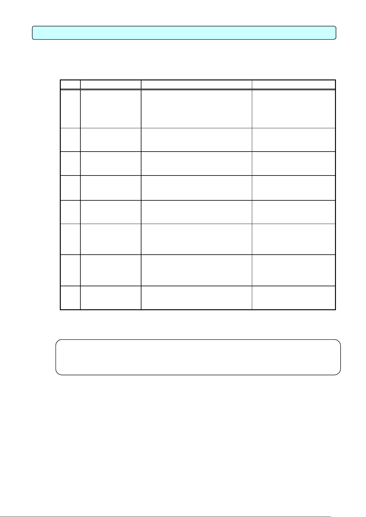
2.1 Requirements (system recommendations)
We recommend the following software and hardware when using this application (TG-2000A).
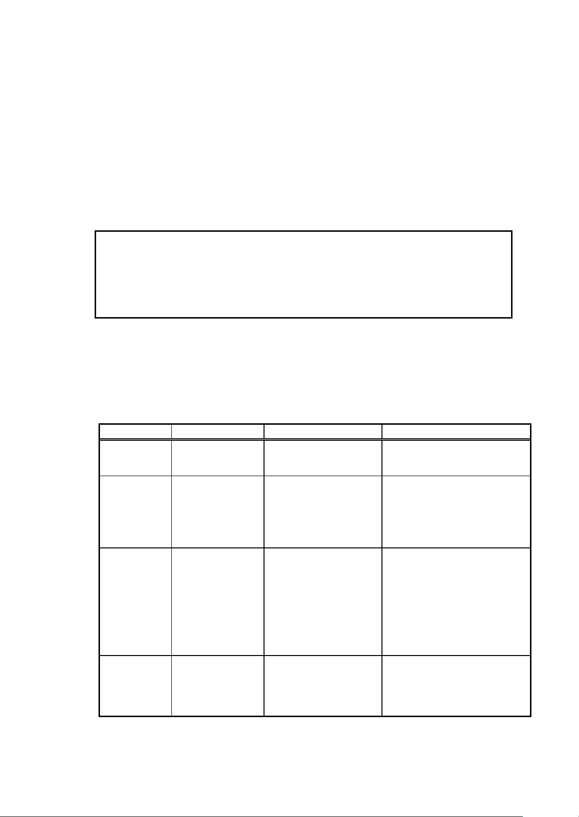
Item Requirement Recommended
PC PC/AT interchangeable machine Operation check completed, using IBM,
COMPAQ, and DELL
CPU Pentium III 350 MHz or faster :
within 1000 indoor units
Pentium III 1GHz or faster :
1001 indoor units or over
Memory 128 MB or more 256 MB or more
HDD 6 GB or more (2GB or more of C drive free
space necessary)
Storage device FDD, CD-ROM drive Devices other than those shown at the left may
Resolution 1024 × 768 or higher, 65536 colors or more
Serial port 1 port or more Required when using RS-485 communication WHM
LAN Internal LAN (10/100 Mbps) *1
OS Windows XP Professional
Windows 2000 Professional
Service Pack 2 and above
Other Computer must be dedicated for this use
(TG-2000A).
Pentium 4 1.8GHz or faster
4 GB or more of C drive free space necessary
also be installed.
English version only
* Personal computer must support each OS.
*1 Purchase the option, or use the equipment recommended for the personal computer when
purchasing the personal computer.
2.2 Compatible Units
The TG -2000A has two main functions: air conditioner controller and cost accounting. However, not all
functions are available with all air conditioners.
Table: Compatible units and function list
(¡: supported, : Certain restrictions apply, ×: Not supported)
Function
Model
Y series ¡ ¡ *1
Super Y series ¡ ¡ *1
R2 series ¡ ¡ *1
WR2 series ¡ ¡ *1
WY series ¡ ¡ *1
Multi S series ¡ ¡ *1
Free plan Indoor unit
Free plan LOSSNAY
LOSSNAY with he
humidifying
“A” control type ¡
“K” control type ¡
*1 : Can be calculated for each charging block.
May not be available with some older models.
Control/
Maintenance
¡ ¡ *1
¡ ×
¡ ×
(Adapter required)
(Converter required)
Charging (Billing)
without WHM
×
×
Charging (Billing) with WHM
required.
watt-hour units)
required.
watt-hour units)
required.
watt-hour units)
required.
watt-hour units)
2
Page 6
2.3 Restrictions
The following restrictions apply to the TG -2000A application.
(1) System configuration limits
Number of units Notes
G-50A Max. 40 units G-50A Ver. 2.10 or higher
Indoor unit Max. 50 units/G -50A Max. 2000 units (including all IC, KIC, AIC, LC, and FU)
[Symbol]IC: Indoor unit, LC: LOSSNAY, FU: OA processing unit, A IC: “A” controller,
KIC: “K” controller
(2) Group setting restrictions
Item Restrictions Note
Remote controls 2 per group * Other remote controls besides M-NET
Number of indoor units
connected to a group
Number of SC and RC
connected to a group
Groups per floor Max. 50 groups per floor Up to 50A groups can be displayed on
*1 The ME remote controller and MA remote controller cannot be used together for the same group.
*2 Set the same function unit for the group.
[Symbol]SC: System controller, RC: Remote controller
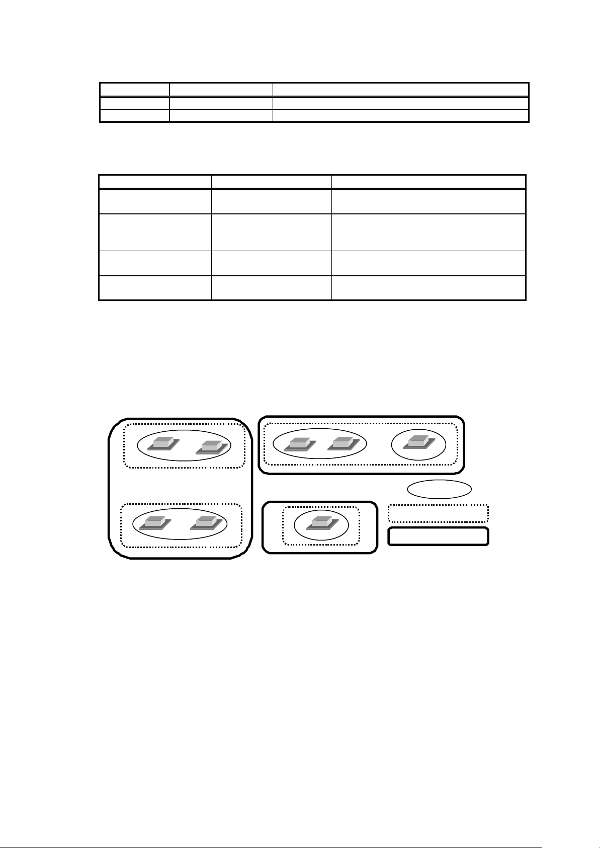
(3) Block setting
• The block comes in two types, operation block and charge block.
• The operation block is an aggregate of groups, and it is possible to set a different model group
for the same operation block.
• The charge block consists of an aggregate of operation blocks.
(4) Notes on using K control models
When using a K transmission converter (model name: PAC -SC25KA, PAC-SC25KAA(-E)) to manage K
control models, take note of the following. See the documentation provided with the K transmission
converter for more detail.
• The address of the K transmission converter will be the smallest address of the K control model +
200.
• Set the K control model addresses so that they are larger than the M transmission model
addresses.
• When setting a group containing K control models, make the group number the same as the
smallest unit address in the group.
(5) Notes on using A control mode
• Use the A/M NET Adapter (model name: PAC-SF48MA(-E)). Set the group to “Group with only
A control”.
(6) Countermeasure when an error occurs
• Note that each control or function may not operate properly when rebooting (*1) or when a fault
occurs in the centralized Controller G-50A. Since each error is displayed when it occurs, it is
recommended to solve the faults quickly.
*1 Indicates that the system is restarting.
1 to 16 * IC, AIC, KIC, or LC cannot be used
4 per group * The number of G-50A is not included
type will not work
within the same group. It is not pos-
sible for group settings to span G-50A
one floor of the whole building window.
Group
Block for operation
Block for charging
3
Page 7
(7) Notes on charge system
485 output of
Necessary when measuring the
F or
att hour meter 2,
Installation is recommended to
billing (Charge data) and other
use
• If there is a group that is not set in the charge block, the electric power amount for that group will
not be included in the air-conditioning charge. If there are groups which require charging to be
divided, set those groups as operation blocks or charge blocks to accomplish this.
• The air conditioning charge can be calculated by block units or by power meter units. Note that
even when OA processing unit, LOSSNAY, A control unit or K control unit are included in the
block setting, they are not included in the air conditioning charge of the block unit.
• The function for Charge calculation (Without WHM connection) is only applicable to the indoor
unit. It does not apply to OA processing unit, LOSSNAY, A control unit, and K control unit, etc.
• Some older M-NET control indoor units are not compatible with the charge function.
• When the system is changed or the air conditioner is extended, which may require address
changes, the charge calculation may be affected in some cases.
Executing such changes or extensions are recommended after gaining approval from the
building owner(s).
(8) Charging (Billing) restrictions
The air conditioning cost calculation method use by this integrated software TG -2000A is the
Mitsubishi proprietary general electric power apportioning method. Thus, it is not calculated
using watt hour meters installed at the power supply to each unit. Additionally, it cannot be
employed in applications demanding calculations based on watt hour meters installed at each
unit. Thus when using this unit, we recommend a separate contract be established between the
building owner and the tenant that specifies “air conditioning fees will be collected based on
proport ional usage (including special considerations for downtime).”
(9) Function description
• The function/specifications may partially change and improvements may be made without any
notice.
2.4 Other Devices
Other devices specified or recommended for use with the TG-2000A are listed below.
Name Manufacturer Model Notes
Printer (None specified) (None specified) Supports a page printer only
Watt hour meter 1 Northern Design
RS -232C/
RS -485
converter
UPS
(Uninteruptable
power supply)
1 POWER RAIL 323 +
(Electronics) Ltd.
2 Elcomponent
Limited
3 CIRCUTOR
4 elcontrol energy
(None specified) (None specified)
(None specified) (None specified)
OPTION Module
2 AEM31D/485
3 CVM-BC-ITF-RS485-
C2
4 ED39din 485
(Must run under the OS used
(Windows 2000/XP Professional).)
Only supports RS the specified model and
manufacturer
electric power.
Ex) B&B Electronics Model
485DRJ
Black Box Model IC520A IC108A
* Regarding w
the converter from the manufacturer may also emit light.
prevent destruction or loss of
data. (Any type suitable for
with personal computers)
4
Page 8
3. System Configuration
controller
G-50A
G-50A
Integrated software
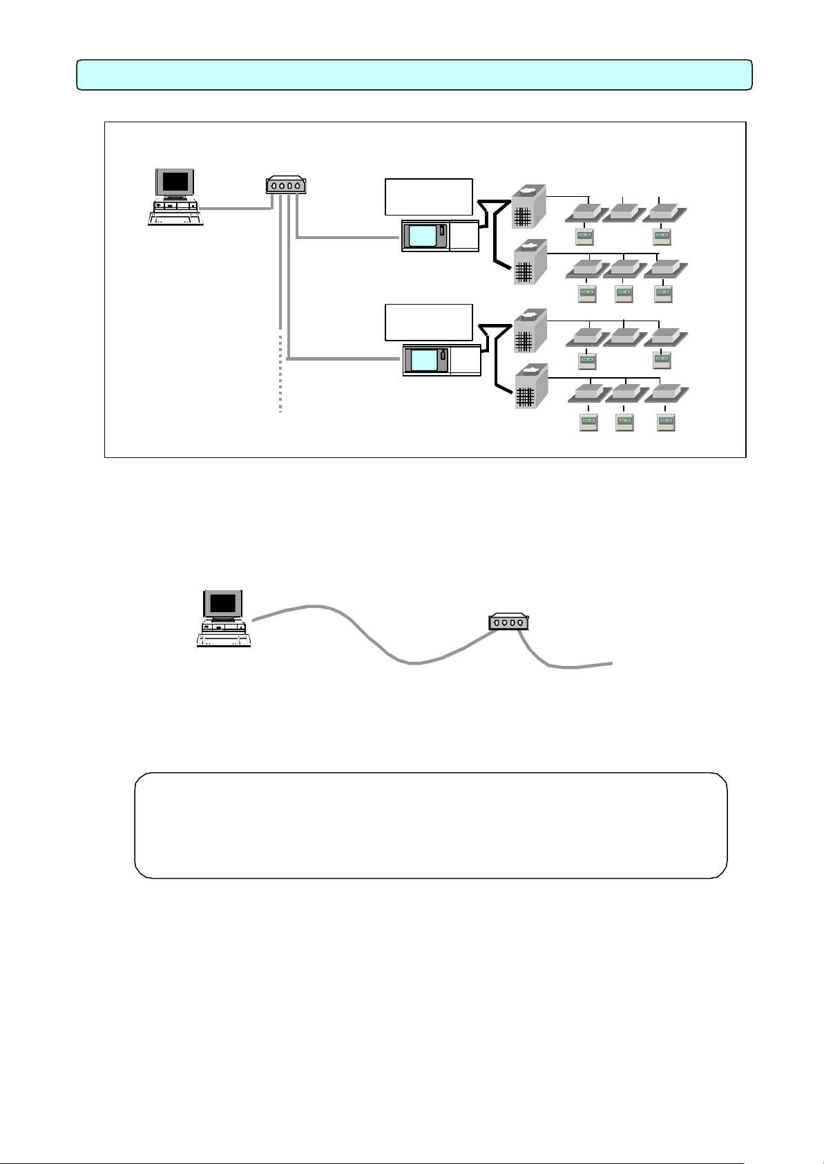
3.1 System Configuration Example
[Image drawing]
HUB
LAN
Integrated software
TG-2000
3.2 Hardware Connection Diagram
(1) LAN connection
Connect the LAN cable to the personal computer. For the location of the LAN connector for the
personal computer, refer to the Instruction Manual of the personal computer.
LAN
TG-2000
Note:
• Be sure to use the hub.
• Execute the LAN cascade connection as shown below.
For 10BASE-T, the cascade connection is executable up to a maximum of 4 sta ges.
For 100BASE-T, the cascade connection is executable up to a maximum of 2 stages.
Power
supply unit
Power
supply u
10BASE-T
straight cable
Outdoor unit
Indoor unit
Remote
HUB
To G-50A
5
Page 9
ners and controllers
PC connections and settings
-
machine system can correctly operate air conditioner units of all
4. Flow of Site Adjustment
For the test operation method of the air
50A,
that only the air conditioner test
operation has been completed before
Power
G- 50A
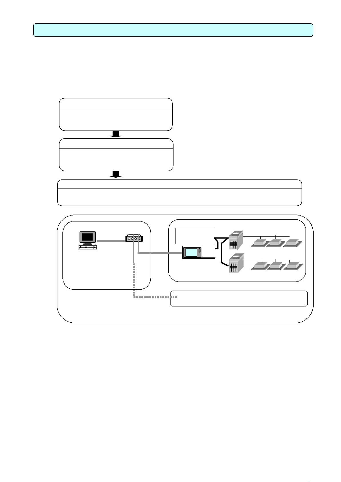
4.1 Flow of Site Adjustment
When the task of site adjustment is subdivided into smaller tasks as shown in the figure below, the
tasks can be broadly grouped into three steps. The benefit of following these three steps when
carrying out the tasks of site adjustment is that if troubles do arise, it will be clear which step caused
the problem. This makes it easier to solve problems and this results in a more efficient execution of
site adjustment tasks.
Carry out site adjustment, by following the step by step instructions shown below.
Check that the air conditio
are correctly configured and that the air conditioner works.
Step 2
Connect and set up the software and hard
ware on the PC with TG -2000A installed.
Check that it is ready for operation.
Check that the TG -2000A manthe managed systems by issuing TG -2000A commands.
Step 1 G-50A test run
Integrated centralized
control software
TG-2000A
Step 2
S tep 3
4.2 Tools for Site Adjustment
You will need the following equipment and reference material in order to easily carry out site adjustment.
<Measurement instruments>
• Tester : to check the wiring and the voltage
<Reference material>
• All necessary drawings of the air conditioning control system
• TG-2000A Instruction Manual (Site Adjustment (this manual), Management)
• Operation Manual for each air conditioner unit and controller
<Ot her material>
• Floppy disk : used when copying data
• CD-R : used to store generated data and copy it to the site PC.
• Initial setting tool: Personal computer in which this tool is installed
• LAN cable : PAC-YG00FA LAN cable
• Screwdriver kit
• Other usual maintenance tools
*
conditioner and centralized controller Grefer to the relevant installation manuals.
l Check
starting Step 1.
* See Chapter 4 in this booklet for details.
Step 3 TG-2000A system test run
HUB
supply unit
LAN
S tep 1
Step 1
6
Page 10
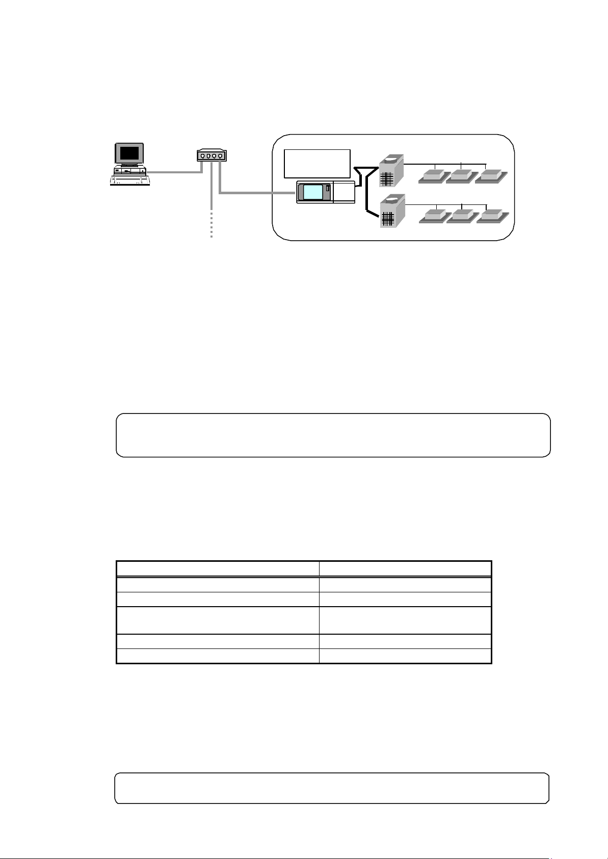
4.3 Step 1: Test operation from centralized controller G-50A
Perform only the test operation of the air-conditioning system of the central controller G-50A.
(1) Preliminary check
Check that the test operation of the air conditioner has been completed.
Check that the central controller G-50A is set to Group and Interlock.
(The initial setting is executable using the initial setting tool or the G-50A.)
Integrated centralized
control software
TG-2000A
(2) Test operation from central controller G-50A
After supplying power to the central controller G-50A and all air conditioners, perform the test
operation from the central controller G-50A, and check the operation state of each unit.
* For the test operation method, refer to the installation manual for the air conditioner or the
central controller G-50A.
HUB
Power
supply unit
G-50A
S tep 1
4.4 Step 2: Initial setting of integrated centralized control software TG-2000A
(1) Set -up of integrated centralized control software TG -2000A
Make preparations to allow the personal computer to be operative in order to install the integrated
centralized control software TG-2000A. After performing the set-up preparations, set up the
integrated centralized control software TG -2000A.
(2) Check the G-50A IP address and personal computer (which uses the integrated centralized control
Note:
• For the set -up procedure, refer to Chapter 5.
• For safety, check the installation state/connection before turning the power ON.
software)
Check the G-50A IP address. Check the IP address used for the integrated centralized control
software at the same time. Normally, set the sub-net to "255.255.255.0".
For a LAN dedicated to the G-50A system, it is recommended to set the IP address
within the following range.
Models IP address range
G-50A main unit [192.168.1.1] to [192.168.1.40]
Personal computer for browser [192.168.1.101]to [192.168.1.149]
Personal computer
for integrated centralzed control software
PLC [192.168.1.151]to [192.168.1.200]
Personal computer of initial setting tool [192.168.1.201]
* To connect to the existing LAN, set the IP address and sub-net mask set by the LAN manager.
(3) LAN connection confirmation
Check that the LAN cable is connected to the G-50A, personal computer (using integrated
software), and hub, and that power is supplied to the hub.
(4) Initial setting of integrated centralized control software
Start the integrated centralized control software TG -2000A to execute the initial setting.
Note:
• For the initial setting method of the integrated software, refer to Chapters 6 to 8.
[192.168.1.150]
7
Page 11

4.5 Step 3: Test operation from integrated centralized control software TG-2000A
2000A to
execute the test operation/confirmation. (The test operation function is not included in the
Perform the test operation from the integrated centralized control software TG-2000A to check the
operation state and monitor display of the air conditioner.
For the operation procedure, refer to the Instruction Manual (Management).
Note:
• For confirmation in the test operation, use the checklist shown in Chapter 11.
• Perform the normal operation from the integrated centralized control software TGstart/stop function.)
8
Page 12
If not the correct version,
Check that there is at least 128 MB of
Check that there is at least 2GB of free
the C drive. (OS already set
Install the printer driver and check that
For details, refer to the
In the Windows Control Panel, select
Time” and set the date, time
For details, refer to the
At the “display” in the Windows Control
the screen size to 1024 × 768
color to 65536 colors
For details, refer to the
cedure, see Appendix 2
t the network settings have
performed (even if the adapter is
For details, refer to the
5. Installation
2000A will not be started automatically after starting (rebooting) the personal computer
2000A is set
5.1 Pre-installation Steps
Preparing for installation
Before installing the TG -2000A application, do the following checks and preparatory steps.
Steps
1 Check the OS Check the OS Service Pack version.
2 Check the memory
3 Check the HDD free
4 Printer settings
5 Set the date and time
6 Screen size and color
7 Automatic login
8 Network settings Check tha
*1 Check when using the printer.
*2 Auto log-in sets the automatic start-up without entering the log-in name or password at the OS
start -up.
Note:
• The TG when the TG -2000A is set to Auto reboot, unless the Auto log-in is set. When the TGto Auto re-boot, be sure to set the Auto log-in.
5.2 TG-2000A Setup
5.2.1 Setup
The following shows the TG-2000A setup disk (CD-ROM) folder configuration and files. However, it
only describes the files to be run.
CD-ROM drive \Setup\Step1\MSDEInst.bat
\ Step2\DbSetup.bat
\ Step3\SetupTG.exe
[Reference] CD-ROM directory structure
readme.txt : Directory structure and setup precautions of this CD-ROM
\ Setup : Set -up folder
\Tool : Air-conditioning charge calculation support tool (chargecalc.xls)
\ Manual : Operation Manual
Action Details How to
space
settings
settings
*
• Windows XP Professional
• Windows 2000 Professional: SP2
and above
RAM (256MB or more is
recommended.)
space on
up)
printing is possible.
“Date and
and region
Panel, set
or larger and the
(High Color (16-bit)) or more.
Check that the Auto log-in is set. *2 * For the setting check pro-
been
not connected).
9
refer to the attached
documentation, “Installing
• Windows 2000/XP” and
upgrade the OS.
* If necessary, add more
RAM.
* Refer to the Windows
instruction manual for
more details.
*
attached instruction
manual.
*
Windows users manual.
*
Windows users manual.
Auto Log-in Check Proce dure.
*
Windows users manual.
Page 13
5.2.2 Running TG-2000A Setup (New setup)
Restart the personal computer after completing the
up. Otherwise, Step 2 which follows may
The TG -2000A setup is performed in three stages:
Step 1) MSDE setup
Step 2) Database setup
Step 3) TG-2000A setup
Note:
• Perform the 3 setup steps sequentially. Otherwise, the TG-2000A will not operate properly.
• Be sure to log -in to Windows, using the Auto log-in name and password before executing the set-up.
(It is necessary to execute the log-in with a log-in name having administrator rights.)
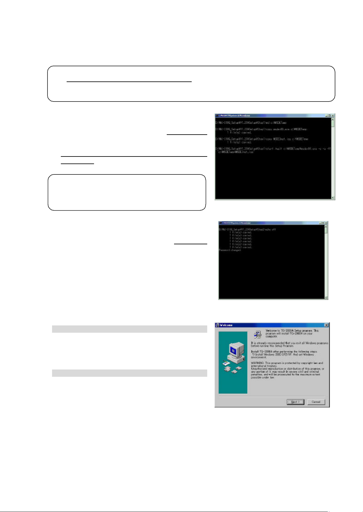
Step 1) MSDE setup
Run the “MSDEInst.bat” file in the “\Setup\Step1” folder.
A DOS window will ope n and the close 2 or 3 minutes
later when the process has finished.
When the installation is completed, restart the
computer.
Note:
•
MSDE setnot be able to be set up properly.
Step 2) Database setup
Run the “DbSetup.bat” file in the “\Setup\Step2” folder.
A DOS window will open and the close 10 se cond s
later when the process has finished.
Step 3) TG-2000A setup
Run the setup program for TG-2000A. Perform the
setup in accordance with the instructions on the
screen.
(1) Starting the setup program
1) Starting SetupTG.exe
Use Windows Start -Run to execute Run SetupTG.exe
in the “\Setup\Step3” folder in the root directory of the
Setup CD.
The setup start confirmation window appears. Read
and check the cautions which appear on the screen.
2) Check the displayed items and click the [Next] button.
If there is no problem with the cautions, click the [Next]
button to continue on to the next screen.
* Click the [Cancel] button to stop the setup.
10
Page 14

(2) Read the license agreement
Be sure to restart the personal computer after
1) Read the license agreement and click the [Next] button.
The license agreement screens will be displayed one at
a time. Carefully read all of the agreement and check
that you agree with each item before selecting “It
agrees” and clicking [Next] to continue.
* If you cannot agree with the license agreement,
click the [Cancel] button and stop the installation of
TG-2000A.
(3) Check the installation folder
1) Check the location where the program is to be installed
and click the [Next] button.
Check the location where the program is to be installed.
If the location needs to be changed, set the new
location by clicking the [Browse] button.
After checking the installation location, click the [Next]
button.
* Click the [Cancel] button to stop the installation.
(4) Installation start confirmation
1) Confirm that you want to start the installation and
select the [ Next] button.
If the [ Next] button is clicked the installation will start.
* Click the [Cancel] button to stop the installation.
(5) TG-2000A setup completion
1) Select [ Finish] button
Click [Finish] button on installation screen.
After the installation is completed, restart the computer.
When the installation is completed, the program is
registered in the start menu and automatically run from
the nex t time the computer is started.
Store the CD is a safe place.
Note:
•
installing TG -2000A.
11
Page 15
5.3 TG-2000A Uninstall
This section describes how to uninstall an installed “MSDE” and “TG -2000A” program.
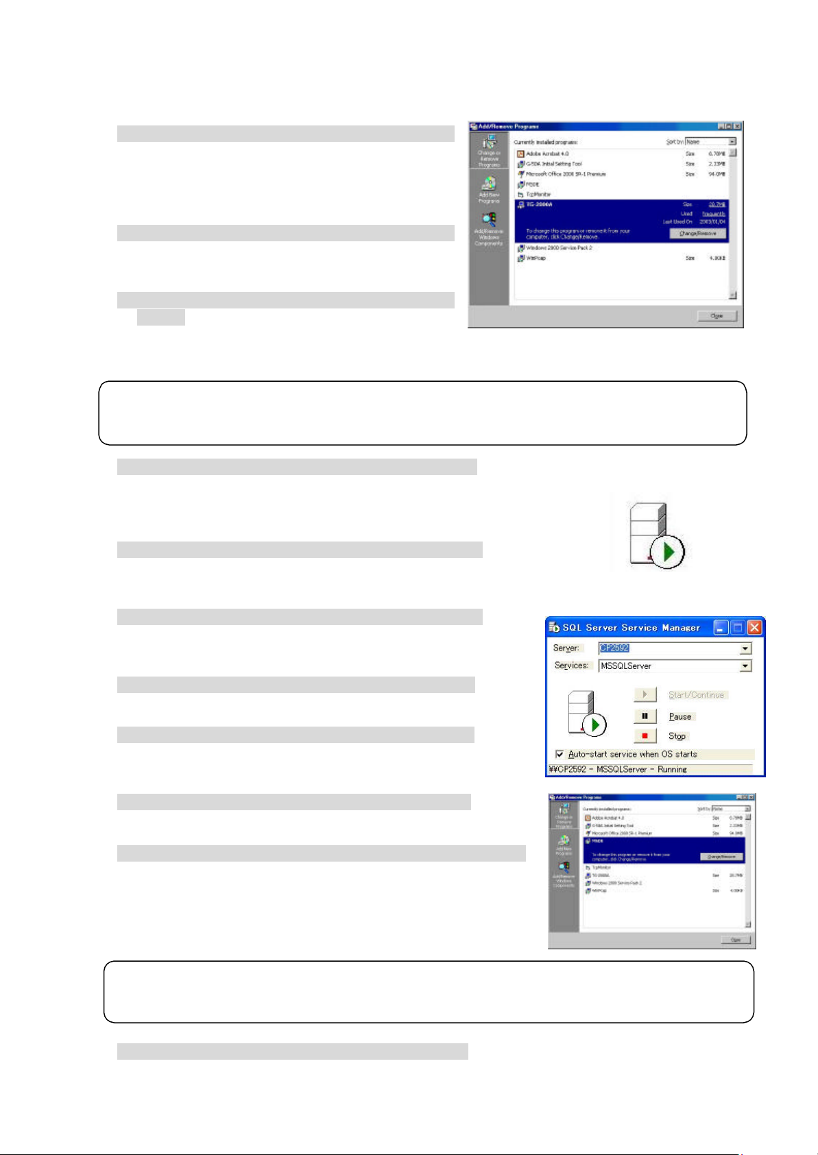
(1) TG-2000A uninstall
1) Check to see if TG -2000A has ended
Check to see if the TG-2000A program has ended. If
it has not ended, end it.
* For a description of the ending method, see
Chapter 7.
2) Start “Add/Remove Programs”.
Start by clicking Control Panel’s Add/Remove Programs.
3) Select “TG-2000A”, and click [Change/Remove]
button.
Select “Integrated centralized control software
TG-2000A” from the displayed programs, and click the [Change/Remove] button. Uninstallation of
the TG -2000A program begins.
Note:
• We recommend that you do not delete all the shared files.
• This uninstall cannot delete some folders and files. (Ex: C: \TG-2000)
4) “Add/Remove Programs” ending
When program uninstallation ends, Add/Remove Programs ends.
(2) MSDE uninstall
1) Start the SQL Server Service Manager
Start the “SQL Server Service Manager” by right-clicking the MSDE
icon on the taskbar.
2) Stop all service
To stop all service, make your selection at the Service field and
click the [Stop] button.
3) End the SQL Server Service Manager
The “SQL Server Service Manager” window closes.
4) Close the MSDE icon
Right-click the MSDE icon on the taskbar and select [Exit]. The
MSDE icon is removed from the taskbar.
5) Start “Add/Remove Programs”.
Start by clicking on the Control Panel’s Add/Remove Programs.
6) Choose “MSDE”, and click the [Change/Remove] button.
Select “MSDE“ from the displayed programs, and click the
[ Change/Remove] button.
Uninstallation of the MSDE program begins.
Note:
• This uninstall cannot delete some folders and files. (Ex: C: \Mssql7)
• When MSDE is used, uninstall is unnecessary.
7) “Add/Remove Programs” ending
When program uninstallation ends, “Add/Remove Programs” ends.
MSDE icon
12
Page 16
6. Part Names and Functions
functions that may be
-
-
Maintenance group:
Shows the title of the
for the
function, site name, and
Exits the Initial window
Shows time, warnings,
Equipment state
Displays the system
equipment as error or
Display the title of
Message bar:
Display comments
next,
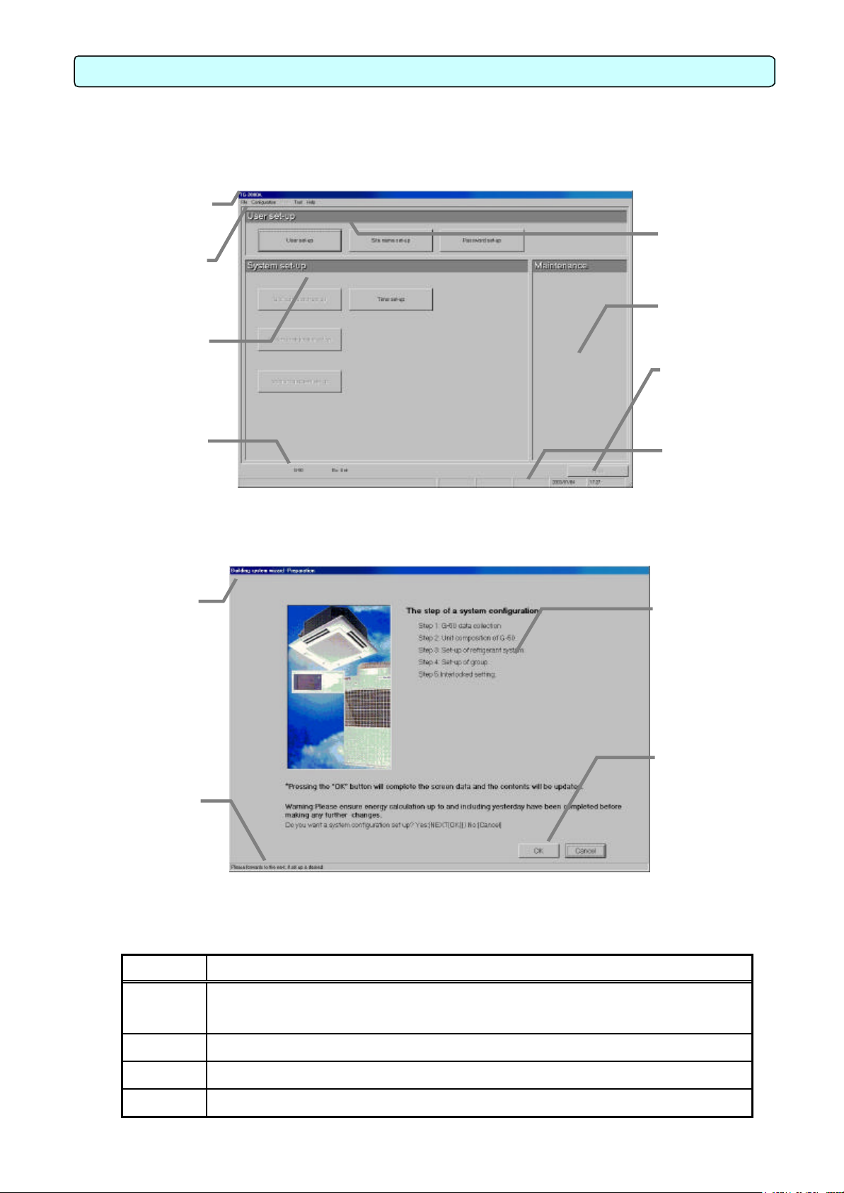
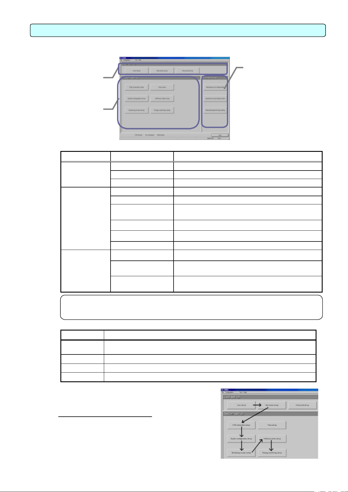
6.1 Window Elements
The window displayed when the power is turned on and no system settings have been made is called
the Initial window. The Initial window has the following parts.
(The Initial window can be accessed from the menu bar with a password. For details, see section 6.3.)
Title bar:
window
Menu bar:
Shows a list of
selected
System setting
group:
Sets the group infor
mation, monitor dis play, charge calcula
tion system, etc.
display:
normal.
Click the buttons to display the window associated with that feature. An example is shown below.
Title bar:
the window.
User setting group:
Sets valid/invalid
password.
Function to correct the
charge calculation, etc.
Exit button:
and moves to the Management window
Message bar:
and other comments
Initial window
Function display operation setting
section:
Used to display/set the setting contents.
about function display and operation
Displays the operation contents of the [Next], [Back], [Cancel], and [OK] buttons on each setting screen.
Buttons Operation contents
[OK]
Advances to the setting screen with the confirmation contents on the preparation
screen determined not to have any problems.
Validates the contents set on this display screen to advance to the next setting screen.
[Next] Advances to the next setting screen.
[Back] Invalidates the contents set on this display screen to return to the last screen.
[Cancel] Invalidates the contents set on this display screen to shift to the initial screen.
System Configuration Options Control Window
13
Next, Back, Cancel,
and OK buttons:
Choose to end, return,
or cancel the setting of function display and operation
settings
Page 17
6.2 Basic Mouse Operation
First, use of the mouse as a pointing device will be explained. If a device other than a mouse is being
used, consult with the manual for that device.
The following is a list of terms used in describing mouse operations.
Click : This refers to pressing and releasing the button one time.
To use this function, click the button
Double Click: This refers to pressing and releasing the button twice in quick succession.
Drag : This refers to moving the mouse pointer on top of an object on the screen, pressing
and holding down the button to select the object, then, while holding the button down,
moving the mouse pointer, and the object, to a different location.
Keyboard : Primarily used when entering password, characters, or numerics.
6.3 Accessing Functions and M oving between Windows
The functions of the TG -2000A can be divided into two general categories.
1) Functions that monitor air conditioner operation status and control functions……Initial window
2) Operation and system initialization and charge data maintenance functions (functions used to
accomplish functions in 1) above)……Control window(Management screen)
This section deals mostly with functions in category 2).
(1) Shift from the initial window to the control window
The following shows the procedure to shift from the initial window to the control window. Shift the
screen to the control window after completing the initial setting shown in Chapter 8.
[Procedure]
1) Select [Finish] button.
Click the [Finish] button located on the lower right on
the initial screen. With the above step, the
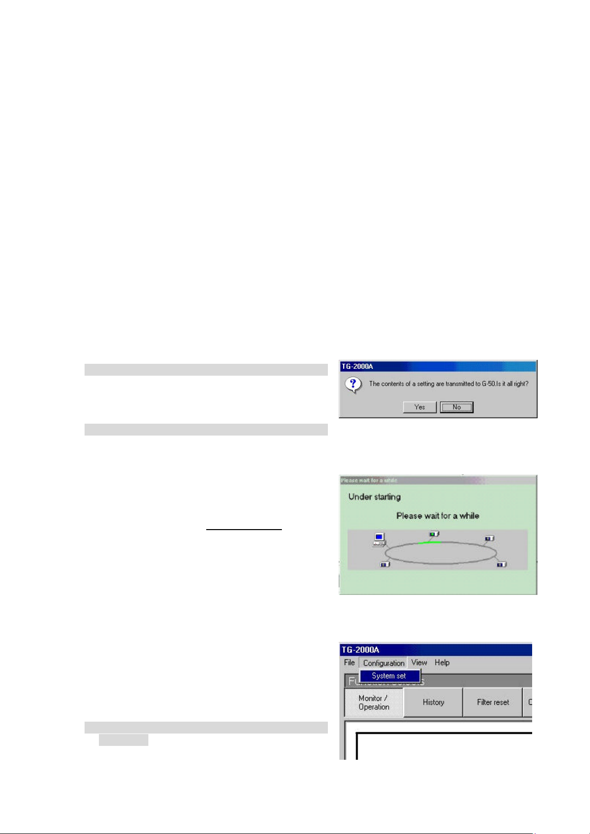
confirmation screen (asking whether or not to trans mit the setting contents to the G-50A) is displayed.
2) Select [OK] button.
Click the [OK] button to transmit the initial setting
contents to the G-50A.
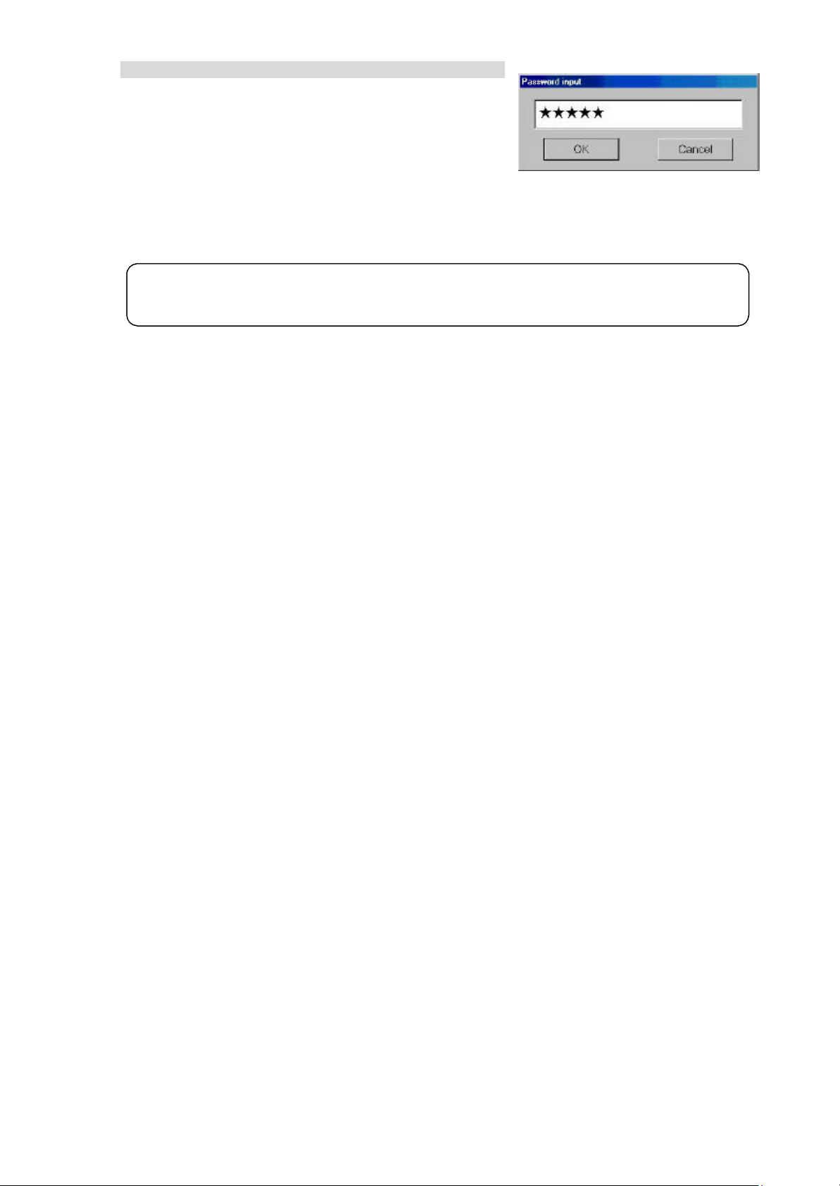
The start-up display screen is displayed after the
screen has been shifted to the control window. The
system information set or changed is transmitted to
each G-50A to enter upon the start -up processing.
It takes approximately 10 to 20 minutes to start-up.
* Note that the setting contents will not be trans-
mitted to the G-50A when the [Cancel] button is
clicked. If it is used when only the maintenance
group function is operated, it is possible to shorten
the time required until the control window
resumes.
(2) Shift from the control window to the initial
window
The control window shifts to the initial window when
the initial setting contents are changed or when the
charge calculation maintenance is performed.
[Procedure]
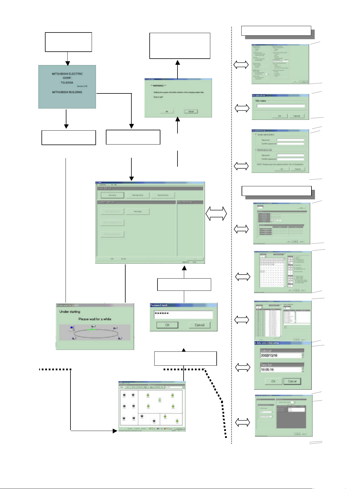
1) Select [Configuration] and then [System set] in the
menu bar.
Click the [Configuration] in the menu bar on the
control window to select the [System set]. The
password confirmation screen is displayed.
Display screen of Shift to setting screen
Screen of confirmation for
transmitting set contents
Start-up display screen
14
Page 18
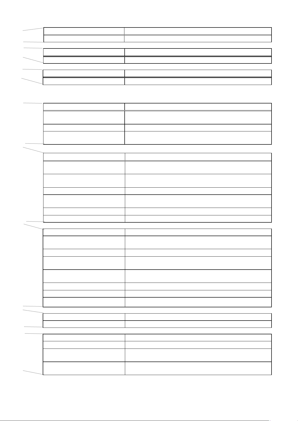
2) Enter the password
Manage the password to prevent unauthorized personnel from accessing the system. The
Enter the word “*****” in the password verification box, then
click the [OK] button. Doing so returns you to the initial
window.
There are two kinds of passwords.
Initialization password: All the items in the initial
window can be used. The
initial password is “SYSTEM”.
Maintenance password: The initial window maintenance group and personal password can be
changed. The initial password is “Maintenance”.
Maintenance Tip
•
password can be changed.
Password input screen
15
Page 19
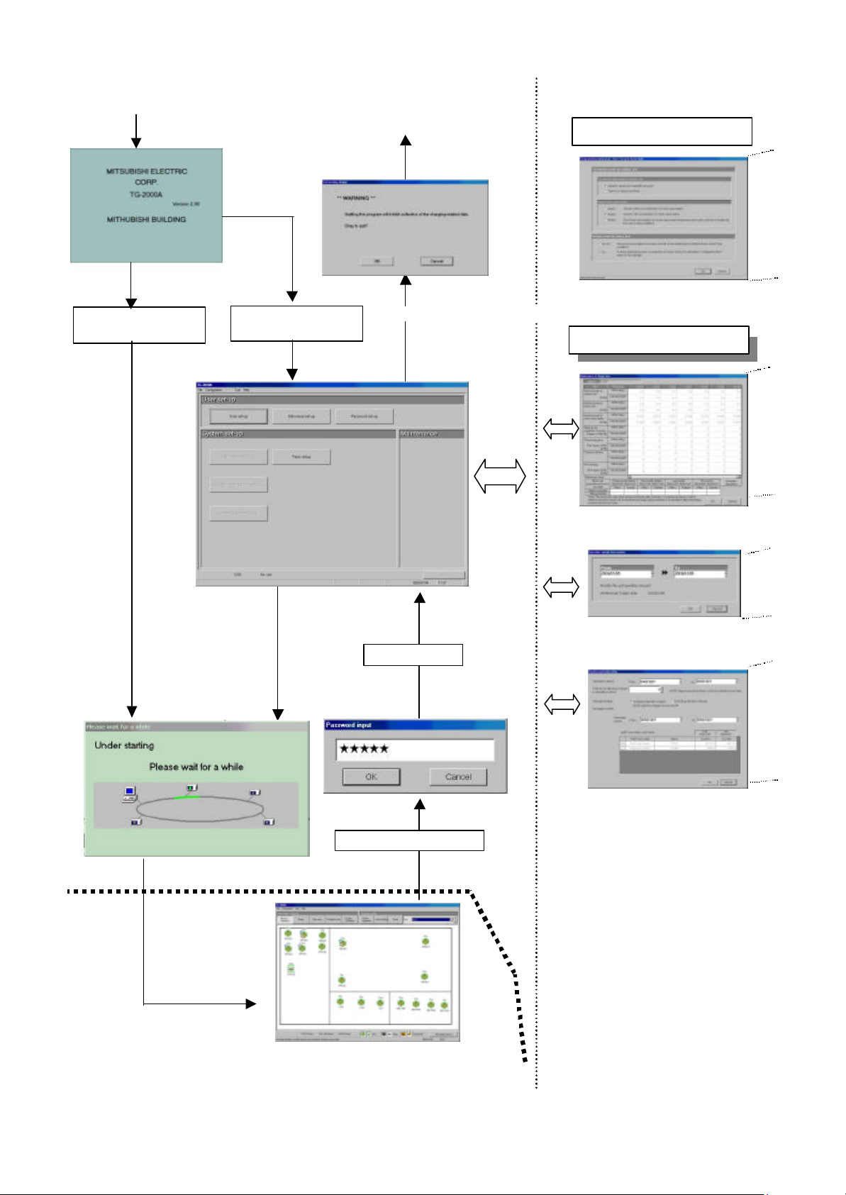
<TG -2000A screen order 1>
turn
]
]
Power On + Start
TG-2000A
System data
No system data
[User setup group]
Exit TG -2000A, shut
down the OS, and
the power off
Select [ File]-[End
button
[System setup group]
Select [ Exit
button
* Range described in this manual
Control window(Management screen)
(see separate management manual)
Password input
Return to Initial window
16
Page 20
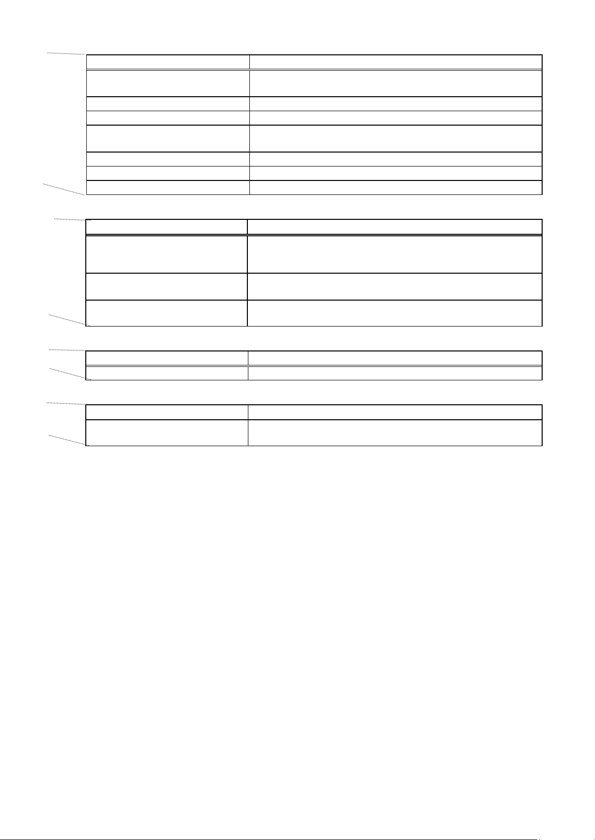
Wizard name Primary settings contained in the activated window
User Set -up Set TG -2000A functions
Wizard name Primary settings contained in the activated window
Site Name Set -up Set the product name (site name)
Wizard name Primary settings contained in the activated window
Password change Changes the password to the two types of Initial window
Wizard name Primary settings contained in the activated window
Preparation for the G-50A
connection setting
Number of G-50A units setting Sets the number of G-50A units.
G-50A IP address setting Sets the IP address for each G-50A.
Wizard name Primary settings contained in the activated window
Preparation for System
configurations setup
Collecting G-50A data Collects the setting information for the G-50A during the initial
Unit configurations setup Sets the unit configurations in G-50A.
System structure of refrigerant
system
Function of each group Set indoor unit and ventilation groups.
Ventilation unit grouping Set ventilators and indoor unit groupings .
Wizard name Primary settings contained in the activated window
Preparation for Monitoring screen
set -up
Set -up of model name Sets the model name of unit
Set -up of the number of floors, and
floor name
Creation of a plane view Create a floor plane to be used in the floor window of the Management
Set -up of floor name and G-50A Set floor and G-50A assignment
Set -up of icon arrange and name Layout icons on the floor plane, and set names
S et-up of block
Wizard name Primary settings contained in the activated window
Time set -up Sets the current time.
Wizard name Primary settings contained in the activated window
Preparation for WHM set -up Check the WHM setting order and notes display .
Watt hour meter setting Sets the watt hour meter connection port and watt hour meter
Set -up for the name and the
maximum count value of WHM
Checks the step/caution display for the G-50A connection
setting.
It is possible to display the optional functions of the G-50A.
Verifies the order of system configuration settings and displays
warnings
setting.
Set refrigerant connections .
Verifies the order of monitoring screen settings and displays
warnings
Sets the number of floors and floor name.
screen(control window)
Set groups in blocks
address.
Sets the WHM name, installation location, and maximum
integrated value.
17
Page 21
<TG -2000A screen order 2>
No system data
System data
Exit TG -2000A, shut down the OS, and turn the power off
Select [File] - [End] button
Select [Exit] button
* Range described in this manual
[Maintenance setup group]
Control windows(Management screen)
(see separate management manual)
Power On + Start TG -2000A
Password input
Return to Initial window
[System setup group]
18
Page 22
Wizard name Primary settings contained in the activated window
Preparation for Energy monitoring
set -up
Model name Sets the unit model No.
Number of floors, and floor name Set floor number and names.
Floor plane drawing Create a floor plane to be used in the floor window of the
Relation between floor and G-50A Sets the number of G-50A terminals.
Group icon placing and naming Layout icons on the floor plane, and set names.
Operation block setting Set groups in blocks.
Wizard name Primary settings contained in the activated window
Maintenance of charge data
(Present value monitor)
Maintenance of charge data
(Meter maintenance)
Maintenance of charge data (Unit) Data for the last 62 days from indoor units and outdoor units can
Wizard name Primary settings contained in the activated window
Operation amount data monitoring Operation data stored in G-50A can be monitored and saved.
Wizard name Primary settings contained in the activated window
Remedial apportioning setting Remedial apportioning can be tentatively performed when
Verifies the order of billing settings and displays warnings .
Management window.
Dat a for the last 62 days from the watt hour meter, indoor units,
and outdoor units can be viewed and edited.
(Also, current values for watt hour meters can be monitored.)
Watt hour meter data from the last 62 days can be viewed and
edited.
be viewed and edited.
charging trouble occurs.
19
Page 23
7. Initial Startup and Shutdown
For safety reasons, make a thorough check of
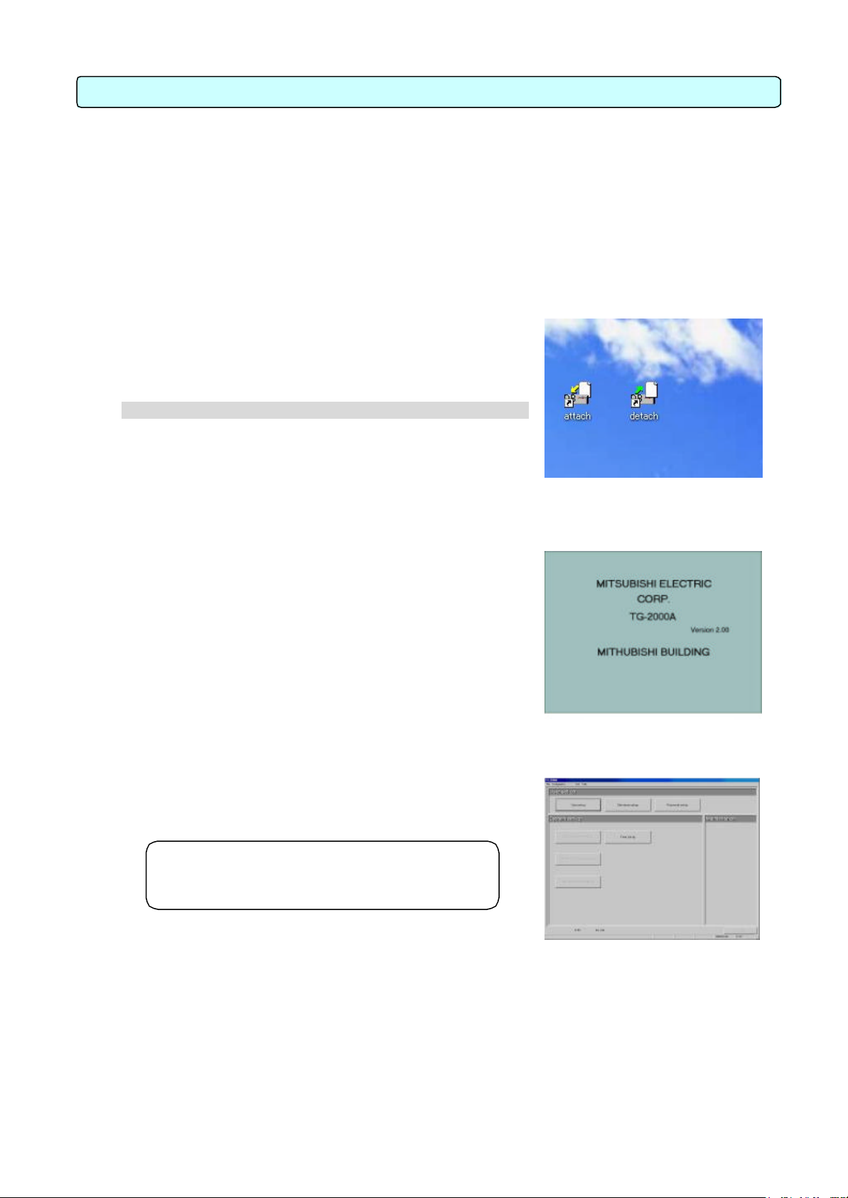
Desktop screen
7.1 Before Startup
Please confirm the following items before starting the TG-2000A application.
(1) A test run of the air conditioning system has been completed.
(2) Check that the personal computer, hub, G-50A, power supply unit, and air conditioner power are
turned on.
(3) All PC hardware and cables have been connected and the proper software installed.
(4) “Date and time” setting are correct.
7.2 Startup
Start the integrated centralized control software TG-2000A
application.
Follow these steps to startup the TG -2000A application.
[Procedure]
1) Restart Windows
When Windows OS restarts, the user automatically logs on
and the TG-2000A program starts. When the startup process
begins, the setup screen is displayed.
* When Windows OS restarts, the integrated software
TG-2000A application starts automatically.
After the startup screen is displayed, the behavior of the
application depends on the existence of System Settings
data.
Case 1: Without System Settings data: (the first startup)
The initial screen is displayed. Start with Chapter 8
“Changing System Settings”
Case 2: With system setting data
After the system has been set up once, turning on the
power brings up the Management window, and the startup
process begins immediately.
The startup process takes some time (approx. 10 to 20 minutes).
To change the initial settings, go to the initial window.
See the procedure in chapter 6.3 “Accessing functions
and moving between windows”.
Maintenance Tip
•
all equipment and connections.
Startup screen
Initial window
20
Page 24
2000A application before
turning off the PC. Failing to do so could result in
2000A application is
When the charge
the operation
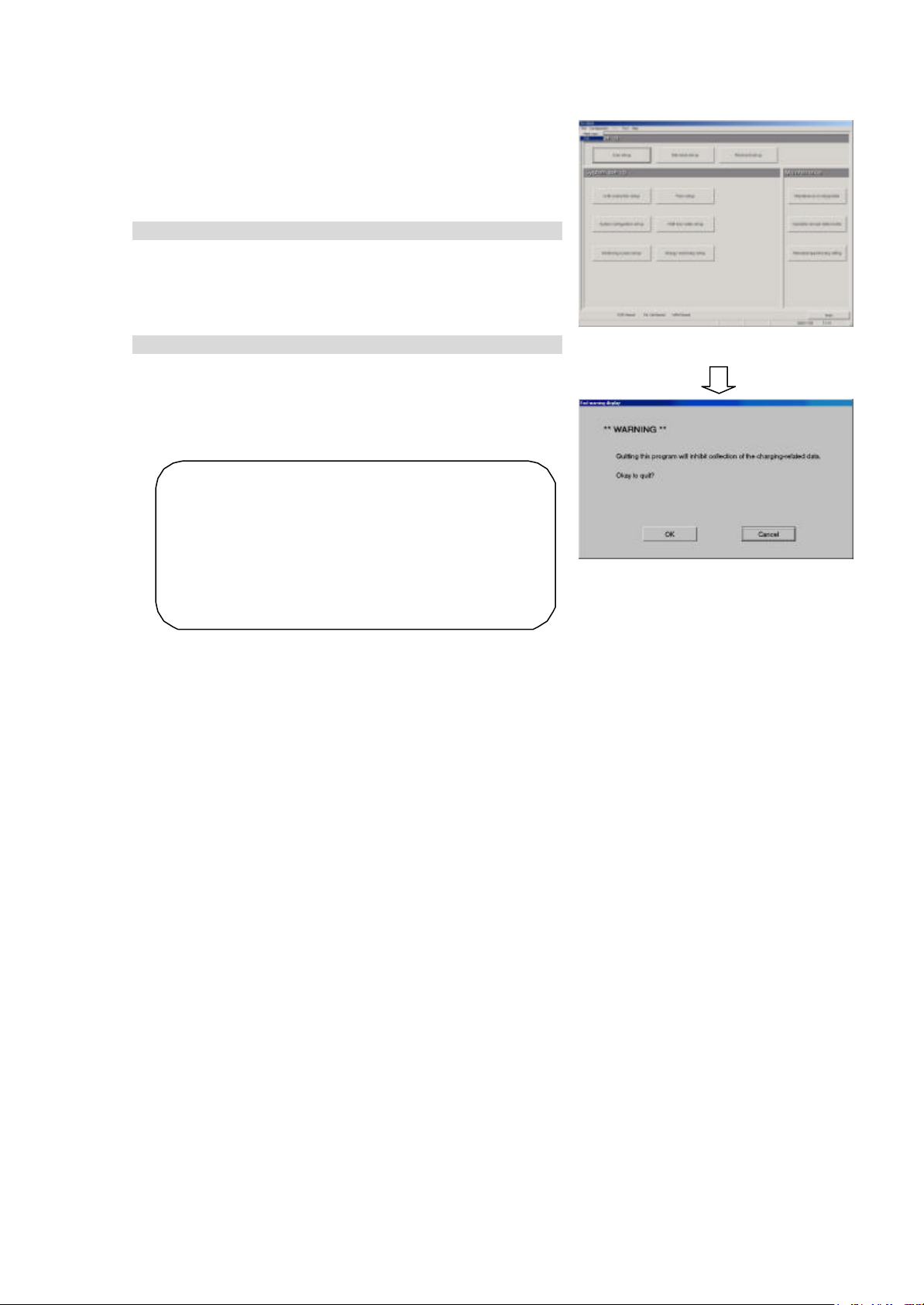
7.3 Shutdown
TG-2000A Shutdown
Follow these steps to shutdown TG -2000A.
[Procedure]
1) Select the E nd option in the File menu in the Menu Bar
Always end the application before turning off the power.
Shutdown is done from the initial window.
Select the File menu in the Menu Bar and select the End
option.
* To switch to the Initial window, refer to chapter 6.3.
2) Select [ OK] button.
The shutdown confirmation dialog box appears asking to
confirm this action.
After verifying the content of the dialog box, click the [OK]
button to exit the application.
* Click the [Cancel] button to return to the Initial window.
Maintenance Tip
• Always exit the TG damage.
• Note that when the TG exited, the functions used stop.
calculation function is used, set
mode to 24-hour continuous operation.
Shutting down the OS
Shut down the OS (Windows 2000/XP) after verifying that the TG -2000A application has been exited.
Turn off the PC after shutting down the OS.
* Please see the OS or PC owner’s manual for procedures on shutting down the OS and turning
off the PC.
End the application
Shutdown verification
21
Page 25
8. System Setting Procedure
8.1 System Setting Screen
The following is an explanation of the items found in the System Settings window.
User Set-up
group
System Set-up
group
Initial window
Function group Function Operation details
User set- up Allow or disallow certain functions
[User Set- up group]
[System Set-up group]
Site name set- up Set the building name
Password set- up The password can be changed
G- 50A connection set-up Sets the number of G-50A units connected and the IP address.
System configuration set-up Sets the system configuration, group, interlocking unit, etc.
Monitoring screen set-up Executes the model name setting, plane drawing creation, group icon
arrangement, etc.
Watt hour meter set- up Set the watt hour meter serial port and watt hour meter address
Maintenance group
Energy monitoring set-up Set the system billing function
Time set- up Set the current time
Maintenance of charge data Proportional billing information can be revised.
[Maintenance group]
Note:
• See Chapter 9 for the maintenance group items.
• The set items that are displayed depend on the functions of the TG -2000A purchased.
Operation amount data
monitor
Remedial apportioning
setting
Operation amount data stored in G-50A can be monitored and saved.
Remedial apportioning can be tentatively performed when charging
trouble occurs.
Displays the operation contents of the select buttons on each setting screen.
Buttons Operation contents
[OK]
[Next] Advances to the next setting screen.
[Back] Invalidates the contents set on this display screen to return to the last screen.
[Cancel] Invalidates the contents set on this display screen to shift to the initial screen.
Validates the contents set on this display screen to advance to the next setting screen.
(Advances to the next setting screen if it is the preparation screen.)
8.2 System Setting Procedure
The following is an explanation of the System Settings
performed at the Initial window.
When no System Settings exist
User set -up Site name set -up G-50A connection set -up
System configuration set -upMonitoring screen set-up
Watt hour meter set-up Energy monitoring set-up
(Password set-up Time set -up)
22
Page 26
* Even if the G-50A is not actually connected, it is possible to set it in advance as long as
If the settings are done out of order, some items will not be available and others will have to be
Check the time for each
When filter sign automatic display is deactivated, the filter status is not reflected automatically even
ter status is
, it only possible
information such as system configuration, etc. is available.
Note:
•
set again.
• Time set -up and Site name set-up are only performed when necessary.
G-50A with “Time set -up”, and set the time when necessary.
When System Settings exist
Make any changes to the settings.
Note:
• Changing certain settings affects the status of other settings.
• User set -up in particular affect other settings and functions.
• Changing the settings on the left affects the settings on the right.
System configuration set -up > Monitoring screen set -up, Energy monitoring set-up
Monitoring screen set -up > Energy monitoring set -up
Watt hour meter set -up > Energy monitoring set-up
8.3 User Set-up
Use these settings to allow or disallow TG-2000A general
operations, printer, charge (billing), and external I/O functions.
Activating TG-2000A Functions
[Procedure]
1) Click the User set -up button
From the Initial window, click the User set-up button in the
User set -up group. The User set -up window appears.
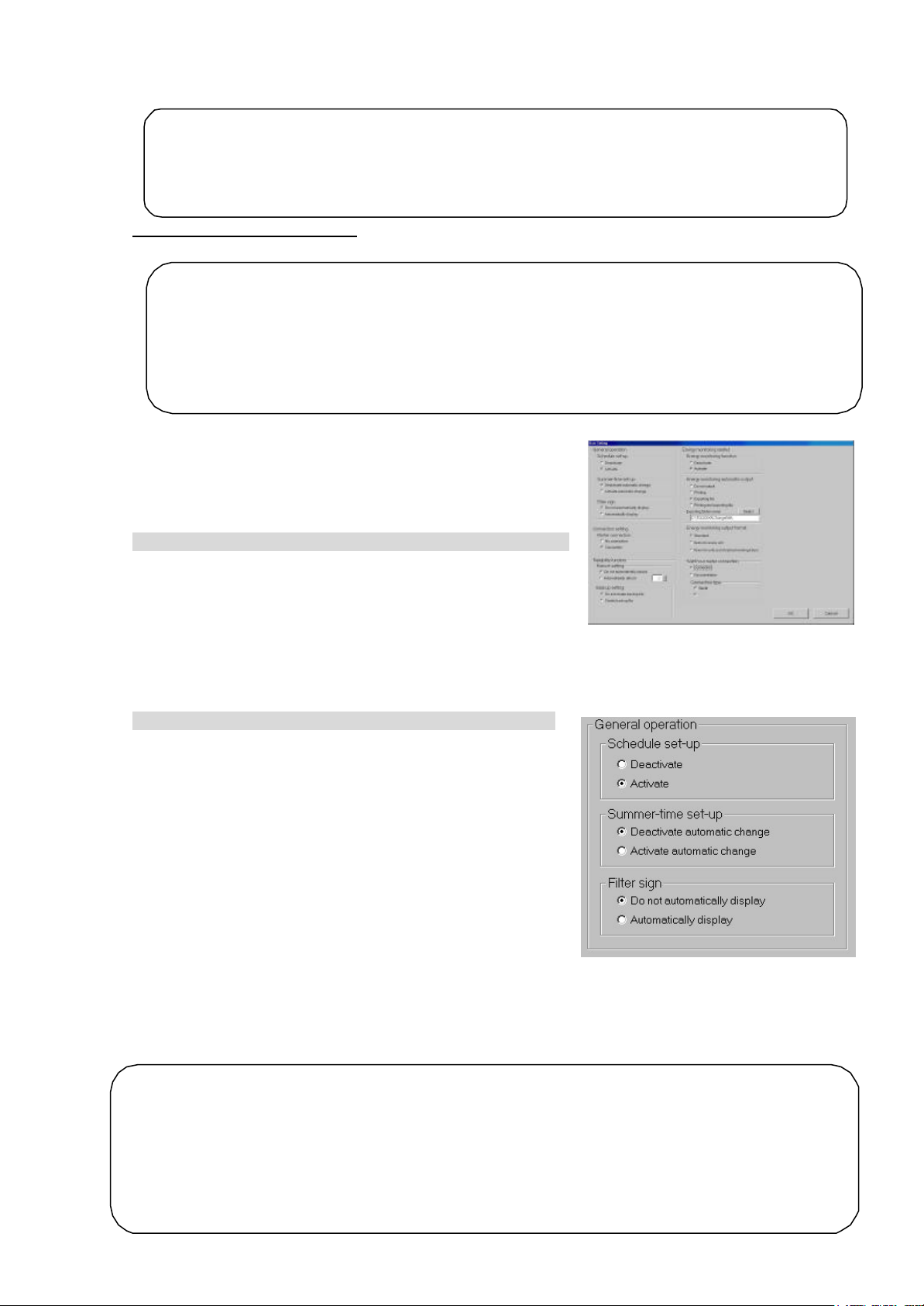
8.3.1 General Operation
Set the schedule and summer time and turn on and off the
filter sign automatic display function.
Setting general operation options
[Procedure]
1) Click the option button.
Set the Schedule Set-up, Summer Time Set-up and Filter
sign automatic display setting. To do this, click the option
button of the setting.
User set -up window
Schedule Set-up
Off (Deactivate) : Turns the scheduling function off.
On (Activate) : Turns the scheduling function on.
(Default)
Summer Time Set-up
Off (Deactivate) : Do not automatically adjust the
G-50A for summer time.
On (Activate) : Automatically adjust the G-50A for
summer time. (Automatic updates
take place at 04: 15 AM) (Default)
Filter sign
Off (Deactivate) : Do not automaticaly display.
On (Activate) : Automaticaly display . (Default)
Note:
•
when the filter sign window is selected. When the View filter button is clicked, the fil
reflected.
• To use the Schedule S et-up, it is necessary to register the license number of the annual/weekly
schedule separately with the G-50A. When the license is not registered with the G-50A
to use the week ly schedule function of the G-50A. In this case, the schedule setting made from the
integrated centralized control software TG -2000A is invalidated, resulting in operation failure.
23
General operation set-up
Page 27
8.3.2 Connection Setting
2000A application and Windows 2000/XP OS on a regular basis
continuously without restarting, system errors may
The automatic restart function serves to insure that the system restart is done on a regular basis.
automatic restart, the system must be restarted manually. Since
it is recommended to periodically restart the
31st
The system configuration, history, and charge data databases are backed up. The trend and
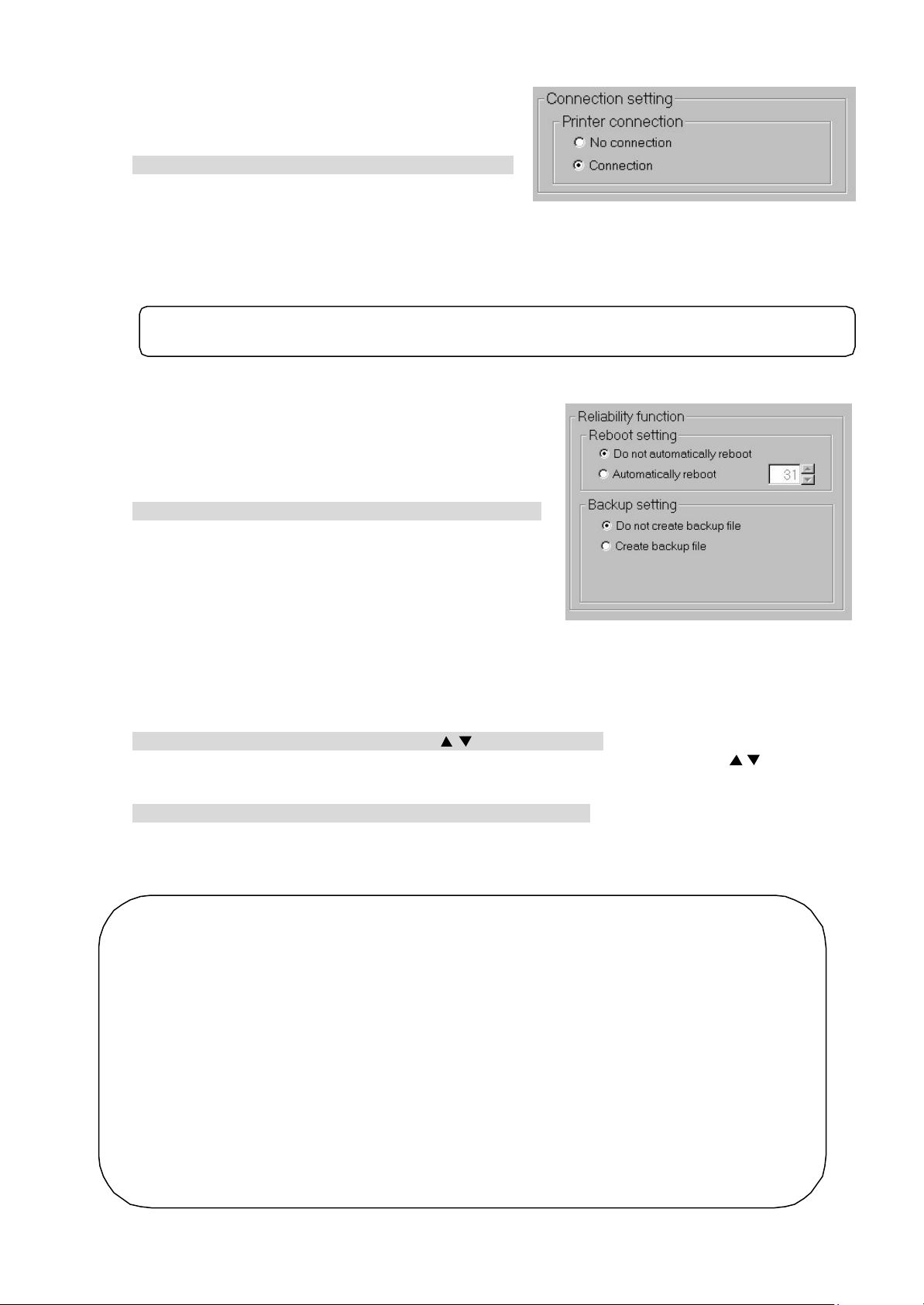
Connection settings
Turn on and off the printer.
Setting connector options
[Procedure]
1) Click the option buttons
Use the option button to select the printer an d WHM
connection.
Available printer options are ON or OFF.
Printer connection
Off (No connection): Turns the printing function off. (Default)
On (Connection) : Turns the printing function on.
Note:
• Data cannot be printed if this option is OFF.
8.3.3 Reliability Function
Turn on and off the automatic reboot function as backup
and the database backup function.
Setting automatic reboot and database backup function
[Procedure]
1) Click the option button
Use the option button to select the Automatic Reboot
function and Database Backup function.
Automatic reboot setting
Off (Deactivate) : Does not automatically reboot.
(Default)
On (Activate) : Automatically reboots.
Backup setting
Off (Deactivate) : Do not back up the database. (Default)
On (Activate) : Back up the database.
2) Select the reboot interval using the “/ ” buttons .
When automatic reboot was set to On, select the automatic reboot day using the “/” buttons.
The setting range is the 7th thru 31st day after booting. The initial value is the 31st day.
3) Set the output folder.
When database backup was set to On, set the database folder to be backed up using the Browse
button. The initial value is “C: \TG2000\databackup”.
* Set the folder to be backed up to an HDD drive different from the C: drive.
Maintenance Tip
• Manually restart the TG-
(once a week). (Perform the restarting operation during the period from 08:00 to 21:45.)
Note:
• When Windows 2000/XP OS is used
accumulate. Thus it is necessary to restart both TG -2000A and the OS.
•
If there is an error during the
there is a possibility of the error not being detected,
system manually.
• When automatic reboot is set to [ON], Windows reboots automatically at 06:35 on the 7th to
day after booting. (The number of days depends on the set value.)
•
display characters databases are not backed up.
Reliability Function Settings
24
Page 28
8.3.4 Energy Monitoring Related
auto
In
of
. If the license is not registered with
, the charge calculation function will not operate properly. It is necessary to register
the " Charge calculation function" license with all G-50A units controlled by the TG-2000A.
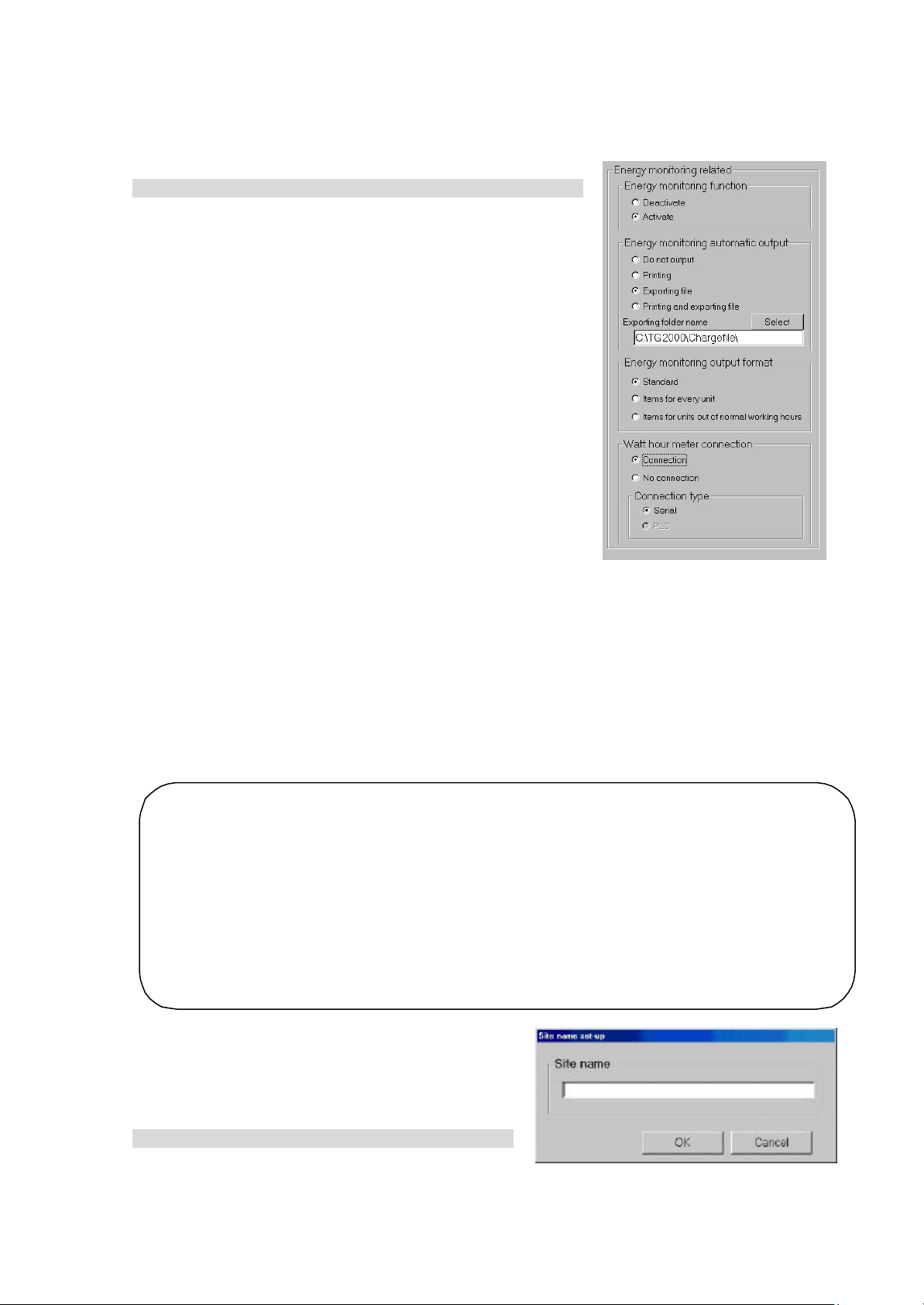
Follow these steps to energy monitoring functions On or Off , automatically print air conditioning
charges, and set printing options.
Energy monitoring functions On or Off
[Procedure]
1) Click the option button
Use the option button to select Energy Monitoring function,
Automatic Air Conditioning Charges Print, or Air Conditioning
Charge Output Processing function setup.
Energy monitoring function
Off (Deactivate) : Deactivates Energy monitoring related
(Default)
On (Activate) : Activates Energy monitoring related
Energy monitoring automatic output
Off (Deactivate) : Do not automatically print air conditioning
charges. (Default)
Printing : Print Energy monitoring auto- matic
printing information auto- matically.
Exporting file : Automatically output air conditioning
charge result as a file.
Printing and : Automatically print and automatically
output air conditioning charges as
exporting file a file.
* For file output, set the output destination. The initial output
destination is “C: \TG2000\Chargefile”.
Energy monitoring output format
Standard : Output by standard item. (Default)
Unit details : Output detailed air conditioning charges for each unit also.
Regular/Off details : Output detailed air conditioning charges for regular hours and off hours also.
W att hour meter connection
Non-connection : Charge calculation function without WHM connected (default)
Connection : Charge calculation function with WHM connected
It is possible to select Serial connection.
* Note that it is not possible for this version to select the PLC connection.
Note:
• When the printer is not connected, it is unable to set the printing for the "Energy monitoring
output".
• When this TG -2000A is not provided with the "Charge function", this screen is not displayed.
order to use the charge function, please contact a Mitsubishi official sales office or supplier.
• The charge function can be set only for either WHM or No WHM.
• The filename is “(Month) (Year) *.csv”. (*: B=Block units, W=WHM units)
• When using the " Charge calculation function", it is necessary to register the license number
the " Charge calculation function" separately with the G-50A
the G-50A
8.4 Site Name Set-up
Set the site name which this integrated centralized
control software TG - 2000A is installed.
Set the site name.
[Procedure]
1) Click the [Site name set -up] button.
Click the [Site name set-up] button in the User
Set -up Group in the Initial window.
Site Name Set -up
25
Page 29

2) Enter the site name.
up
Enter the name of the site on the site name set -up screen from keyboard.
3) Click the [ OK] button.
When finished entering the site name, click the [OK] button.
* Click the [Cancel] button, the site name is left unchanged.
Note:
• Site names may contain a maximum of 20 characters. The site name is reflected upon the start screen and version confirmation screen display.
26
Page 30
8.5 G-50 Connection Set-up
Number of G-50A set-up
Set the integrated centralized control software TG-2000A, number of G-50A units connected, and the
IP address. It is possible for this setting to monitor and display the option functions state of the G-50A.
8.5.1 Setting Procedure and Restrictions
Confirm the precautions and procedure before setting the G-50A connection.
Perform the check before setting the G-50A connection.
[Procedure]
1) Select the [G-50 connection set -up] button.
Click the [G-50 connection set -up] button located in
the system setting group on the initial window.
2) Select the [ON] button after confirming the display
contents.
Check the contents of the alarm displayed. When
there are not any problems found, click the [OK]
button to advance to the setting.
* When the [Cancel] button is clicked, this setting is
terminated to return to the initial screen.
Set the G-50A connection in accordance with the
following procedure.
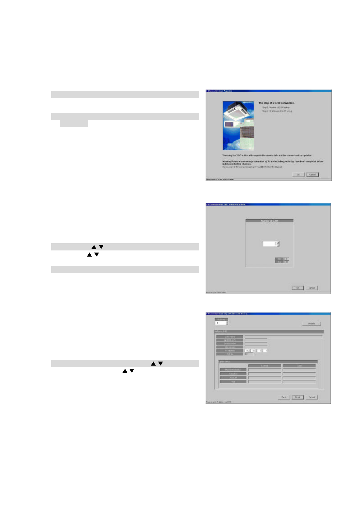
Step 1: Number of G-50 set -up
Step 2: IP address of G-50 set -up
8.5.2 Number of G-50A set-up (Step 1)
Set the number of G-50 connected to the system.
Set-up the number of G-50A
[Procedure]
1) Click the “/ “ buttons.
Use the “
Number of connectable G-50A units: 1 to 40 units
2) Click [ OK] button.
When finished making settings , click the [OK] button.
* When the [Cancel] button is clicked, this setting is
terminated to return to the initial window.
/
“ buttons to set the number of G-50A.
8.5.3 IP address of G-50A set-up (Step 2)
Set the data of the G-50A IP address connected to
the data of the integrated centralized control
software.
Register the G-50A IP address.
[Procedure]
1) Select the G-50 No. with the “/ “ buttons.
In this case, use the “/ “ buttons to select the
G-50A No. for which the IP address information is
registered.
G-50 connection Set -up
27
IP address of G-50A set-up
Page 31

2) Set the IP address.
main unit or initial setting tool.
, and to confirm whether the license
Required when the monitor operation is executed, using this
is
Preparation screen
Input the IP address for the number of G-50A units to be connected.
Set the IP address for the number of G-50A units connected.
3) After completing the setting, press the [OK] button.
After fully completing the IP address set -up for the G-50A units, set the [OK] button, by which the
G-50A connection setting is completed.
* When the [Cancel] button is clicked, this setting is terminated to return to the initial screen.
Note:
• It is necessary to set the IP address for the G-50A using the G-50A
Monitor the optional functions being used.
[Procedure]
1) Select the G-50 No.
Select the G-50A No. desired to monitor the optional function used with the “/ “ buttons.
2) Select the [Update] button.
When the [Update] button located on the IP address screen of the G-50A is clicked, the result is
displayed.
Note:
• It is possible to monitor the optional function of the G-50A
desired to be used for the integrated software TG -2000A is registered (exists).
Web monitor :
(Monitor/Operation)
Annual/weekly schedule: Required when the schedule setting is used.
(Schedule)
Charge : Required when the Charge calculation (charging function)
(Charge calculation)
Sending error mail : Required when the error mail addressing is used.
(Mail) (It is prepared for service maintenance.)
TG-2000A and the Web.
used. (It is also required when the operation time is used.)
8.6 System Configuration Set-up
Set the information of the air-conditioning system to be monitored using this integrated software
TG-2000A. It is possible for this setting to monitor the system information possessed by the G-50A.
8.6.1 Setting Procedure and Restrictions
Confirm the precautions and procedure before setting the system configuration.
Perform the confirmation before setting the
system configuration.
[Procedure]
1) Select the [System configuration set-up] button.
Click the [System configuration set-up] button
located in the system setting group on the initial
window.
2) Select the [OK] button after confirming the
display contents.
Check the contents of the alarm displayed.
When there are not any problems found, click
the [OK] button to advance to the setting.
* When the [Cancel] button is clicked, this setting
is terminated to return to the initial screen.
Execute the S ystem configuration set -up in accordance with the following procedure.
Step 1: G-50 data collection
Step 2: Unit composition of G-50
Step 3: Set -up of refrigerant system
Step 4: Set -up of group
Step 5: Interlocked set ting
28
Page 32

8.6.2 G-50A data collection (Step 1)
data collecting function may cause the system information possessed
execute the initial
e
It is possible to collect the system information (group information, interlocking ventilation unit
setting information, etc.) set for the G-50A with the integrated centralzed control software
TG-2000A during the initial setting.
Caution:
• Note that using the G-50A
in the TG -2000A to be completely cleared. When the information is collected,
setting again as it is written over the G-50A information.
• It can only collect the information when all the G-50A units are connected.
• It is recommended to execute this function after the test operation of the air conditioner and th
G-50A have been completed normally.
Collect the information from the G-50A during the
initial setting.
[Procedure]
1) Select the [Collecting of information from G-50]
button.
To collect the system information from the G-50A
during the initial setting, click the [Collecting of
information from G-50] button.
After completing the information collecting, the operation advances automatically to the next step. Wait a
moment, as it takes time for information collecting.
* When the [Cancel] button is clicked, this setting is
terminated to return to the initial screen.
Skip the collecting information from the G-50A.
[Procedure]
1) Select the [Next] button.
If it is not necessary to collect the informat ion, click the [Next] button.
8.6.3 Unit composition set-up (Step 2)
It is possible to confirm and change the configuration of the unit in each G-50A .
G-50A Data collection screen
G-50A Selection:
Select the G-50 No.
Unit configuration table:
Displays the system
configuration unit of
the G-50 concerned.
Unit configuration address setting
Confirm the unit configuration.
[Procedure]
1) Select the G-50 No. with the “/“ buttons.
In this case, use the “/ “ buttons to select the G-50A No. desired to confirm the unit
configuration.
2) Select the [OK] button after checking the unit configuration of each G-50A .
If it is not necessary to change the unit configuration of each G-50 A when it is checked, click the [OK] button.
*When the [Cancel] button is clicked, this setting is terminated to return to the initial window .
Selected unit icon:
Displays the icons (symbols)
such as the indoor unit, outdoor
unit, remote controller, system
remote controller, etc. and their
names.
29
Page 33

Change the unit configuration.
m controller actually connected. When the
icon is changed, it is possible to display the unit in which the error occurred with the type easily
the
[Procedure]
1) Select the G-50 No. with the “
In this case, use the “/ “ buttons to select the G-50A No. desired to change the unit
configuration.
2) Delete/add the unit icon.
Unit icon deletion: Click the unit icon to be deleted.
Unit icon addition:Click the unit icon to be added from the selected unit icon column to set it to
the selected state.
(The symbol of the selected unit is displayed by the pointer.)
When the address column to be added is clicked, the unit icon is displayed.
Table: Icon symbol and unit name
Icon Name Address range
IC Indoor unit
LC LOSSNAY
FU OA processing unit
KIC “K” Control Units
AIC “A” Control Units
OC Outdoor unit
BC BC controller (master)
BS BC controller (slave)
OS Subsidiary outdoor unit
RC ME remote controller (compact remote controller) /
LOSSNAY remote controller
SC System controller (Including GR, SR, and AN)
GR Group remote controller
SR System remote controller
A N On/Off controller
KA K -transmission converter (201 to 250)
TR Central controller (MJ-103) (201 to 250)
G-50 Central controller G-50 (0, 201 to 250)
?? Unconfirmed unit (1 to 250)
3) Select the [OK] button.
After fully completing the unit icon change, click the [OK] button.
Note:
• When the system information is collected from the G-50A, all the SR, GR, and AN display "SC".
It is possible to change the icon to that of the syste
discriminated.
• Delete the "??" icon displayed, and set the original icon. Note that it is unable to advance to
next step if the "??" icon exists.
/
“ buttons.
1 to 50
51 to 100
101 to 200
201 to 250
30
Page 34

8.6.4 Set-up of refrigerant system (Step 3)
It cannot change the actual refrigerant system even if the addition or deletion is executed on the
refrigerant system information is used for the charge calculation function. When the charge
calculation function is used, be sure to execute the setting and confirmation. This refrigerant
up state. In
Refrigerant
(IC, FU) for
It is possible to confirm and change the information of the refrigerant system within each G-50A.
G-50A Selection:
Select the G-50 No.
system information:
Displays the refrigerant system information for the multibuilding.
Confirm the refrigerant system information.
[Procedure]
1) Click the “/” button to select the G-50 No.
Click the “
2) Select the [OK] button after confirming the refrigerant system information.
If it is not necessary to change or correct the refrigerant system information for each G-50A when it
is checked, click the [OK] button.
* When the [Cancel] button is clicked, this setting is terminated to return to the initial window.
Change the refrigerant system information.
[Procedure]
1) Select the G-50 No. with the “/” buttons.
In this case, use the “/” buttons to select the G-50A No. desired to change the refrigerant
system information.
2) Delete/add the unit icon.
Unit icon deletion: Click the unit icon to be deleted.
Unit icon addition: Click the unit icon to be added, from the unconnected indoor unit icon and
3) Select the [OK] button.
After fully completing the refrigerant system information changes, click the [OK] button.
Note:
•
refrigerant system setting change screen.
• This
system information is used for error occurrence display.
• It cannot collect all the refrigerant system information depending on the G-50A startthis case, execute the addition or change on this refrigerant system setting screen.
The information possessed by the integrated software is compared with the G-50A refrigerant
information when the integrated cenralized control software TG-2000A starts to display the
coincidence or error message of caution in the event of nonreception when this refrigerant system
setting change screen is selected.
/
” button to select the G-50A No. for which the unit Model name is to be set.
unconnected sub-unit columns to set it to the selected state.
(The symbol of the selected unit is displayed by the pointer.)
When the OC column to be added is clicked, the unit icon is displayed.
31
Unconnected indoor
unit:
Displays the indoor unit and OA
processing unit
which the refrigerant system
connection is not displayed.
Unconnected outdoor
sub-unit:
Displays the OS and BC for
which the refrigerant system
connection is not displayed.
Page 35

8.6.5 Set-up of group (Step 4)
When the group setting change screen is changed, it is possible to reflect the changed contents
NET type), K control unit, A control unit, and LOSSNAY for the
number of groups and the number of indoor units connectable to the GR, SR, and AN
Group
Unconnected remote
Group No.:
It is possible to confirm and change the group information of the indoor unit and ventilation unit
within each G-50A .
G-50A selection:
Select the G-50 No.
Displays the group
No.
information:
Displays the group
configuration of the
indoor unit or ventilation unit.
Confirm the group information.
[Procedure]
1) Click the “/” button to select G-50 No.
S elect the G-50A No. to be assigned using the “/” buttons.
2) Select the [OK] button after confirming the group information.
If it is not necessary to change or correct the information of each G-50A when it is checked, click
the [OK] button.
* When the [Cancel] button is clicked, this setting is terminated to return to the initial window.
Change the group information.
[Procedure]
1) Click the “/” button to select G-50 No.
S elect the G-50A No. to be assigned using the “/” buttons.
2) Delete/add the unit icon.
Unit icon deletion: Click the unit icon to be deleted.
Unit icon addition: Click the unit icon to be added, from the Unconnected indoor unit and
Unconnected remote controller columns to set it to the selected state.
(The symbol of the selected unit is displayed by the pointer.)
When the group column to be added is clicked, the unit icon is displayed.
3) Select the [OK] button.
After fully completing the group information changes, click the [OK] button.
Note:
•
on the G-50A system.
• It cannot set the indoor unit (Msame group.
• Since the
is limited, set the group corresponding with such limitations.
This group setting screen displays the number of groups and number of indoor units which allow
the GR, SR, AN, and SC to be newly organized.
Unconnected indoor unit:
Displays the indoor unit, LOSSNAY
(IC, KIC, AIC, LC) not set for the
group.
controller:
Displays the SC, GR, SR, AN,
and RC which can be set for
the group.
Table: Number of management groups and number of indoor units
Symbol Equipment name
Number of management groups
and number of indoor units
GR Group remote controller 8 groups, 16 indoor units
SR System remote controller 50 groups, 50 indoor units
AN ON/OFF remote controller 16 groups, 50 indoor units
SC System controller 50 groups, 50 indoor units
32
Page 36

This group setting screen displays the number of management groups and number of indoor units
Interlocking destination
Note:
•
for the system controller (GR, SR, AN, SC) limited when the group is newly organized.
• It is possible to use the group organization as it is, which is collected from the G-50A.
On/off controller (AN), etc., for instance
Change the group No.
[Procedure]
1) Select the cell of the group No. displayed.
Click the cell desired to change the group No., and the
group No. change screen is displayed.
2) Change the group No.
Use the keyboard to input the group No. to change.
3) Select the [OK] button.
Click the [OK] button after changing the group No.
If there is a duplicated group No., an error message is
displayed.
8.6.6 Interlocked setting (Step 5)
It is possible to confirm and change the information of ventilation unit interlocked with indoor unit
in each G-50A .
G-50A selection:
Select the G-50 No.
Interlocking
ventilation unit:
Displays the ventilation unit (LC, FU) to
interlock.
Confirm the ventilation unit interlocking set-up information.
[Procedure]
1) Select the No. of G-50 with “/” button.
In this case, select the No. of G-50A to confirm the ventilation unit interlocking set -up information
with the “/” button.
2) Select the [OK] button after confirming the ventilation unit interlocking information.
If it is not necessary to change or correct the information of each G-50A when it is checked, click
the [OK] button.
* When the [Cancel] button is clicked, this setting is terminated to return to the initial window.
Change the ventilation unit interlocking set-up information.
[Procedure]
1) Select the No. of G-50 with “/” button.
In this case, select the No. of G-50A to change the ventilation unit interlocking setting with the
“
/
” button.
2) Delete/add the unit icon.
Unit icon deletion:Click the unit icon to be deleted.
Unit icon addition: Click the unit icon to be added, from the Interlocking destination un-set unit
columns to set it to the selected state.
(The symbol of the selected unit is displayed by the pointer.)
When the interlocking ventilation unit display line to be added is clicked, the
unit icon is displayed.
33
un-set unit:
Displays the indoor unit (IC, AIC)
to which interlocking is not set.
Page 37

3) Select [OK] button.
setting screen, it is
] button is clicked, the screen to confirm whether the ventilation unit interlocking
data. When the model name is changed, the
control is carried out
maintenance.
Click the [OK] button after fully completing the ventilation unit interlocking setting.
Note:
• When the ventilation unit interlocking setting is changed on the interlocked
possible to reflect the changed contents on the G-50A system.
• It is possible to set up to 16 indoor units to one interlocking ventilation unit.
• When the [OK
setting is completed, is displayed.
8.7 Monitoring Screen Set-up
Set the information such as the floor name, plan view, operation block, or other items to be monitored/
displayed on the management screen of the integrated centralized control software TG-2000A.
8.7.1 Configuration Procedure and Restrictions
Check these points before setting the system configuration.
[Procedure]
1) Click the [Monitoring screen set -up] button.
Click the [Monitoring screen set-up] button in the
User Settings Group in the Initial window.
2) Click the [OK] button after checking the display
contents.
Check the information displayed and click the [OK]
button.
* When the [Cancel] button is clicked, this setting is
terminated to return to the initial screen.
The monitor display set -ups are done in the following
order.
Step1 : Set -up of model name
Step 2 : Set -up of the number of floors, and floor
name
Step 3 : Creation of a plane view
Step 4 : Set -up of floor name and G-50
Step 5 : Set -up of icon arrange and name
Step 6 : Set -up of block
8.7.2 Set-up of model name (Step 1)
Set the model name of the air conditioner unit
(outdoor unit, indoor unit, sub unit, LOSSNAY etc.)
connected to this system.
Note:
• The Charge function use this set Model name
data is updated and
using that data.
• The Model name can be checked during
Setup the unit configuration model name
[Procedure]
1) Click the “/” button to select G-50 No.
Select the G-50A No. to be assigned using the
“
/
” buttons.
2) Select the unit to be set .
Click the units for which the same Model Name is
to be set. The selected cells are displayed in cyan
and become the objective of Model Name setup. Each time clicked, the unit is alternately selected
and removed. Multiple units can also be selected.
Monitoring screen set -up preparation screen
G-50A setting button
Set-up of model name screen
Set button
34
Model name candidate
Page 38

3) Select the Kind, Type, and Model Name.
are possible.)
When the charge function was used and the Model Name was changed, check the charge
loor
Select the Model Name of the unit you want to set from Kind, Type, Class, and Model Name. (Kind:
IC, LC, FU, OC, BC, OS) The Model Name appears at Model Name candidate.
4) Click the [Set ] button.
When the [Set] button is clicked, the Model Name is reflected as a selected unit Model Name
candidate.
Note:
• The Model Name can be manually entered at Model Name candidate.
• The KIC type is not a database. Enter it manually.
• A remote controller or system controller Model Name cannot be set.
•
setting set contents. The capacity value of each unit is changed.
Removing a Model Name
[Procedure]
1) Select the unit to be removed.
Click the unit whose Model Name you wish to
remove. The cell is displayed
in cyan, and becomes the Model Name setting
objective. Multiple units can be selected.
2) Click the [ Delete] button.
Click the [Delete] button. The Model Name of the
selected unit is deleted.
Frequency setting
[Procedure]
1) Select the frequency.
When the power line frequency is 50Hz, deselect
Use 60Hz. (default)
Select Use 60 Hz only when using 60Hz power.
Ending unit Model Name setup
[Procedure]
1) Select the [OK] button.
After fully completing the type name setting of the G-50A unit, click the [OK] butto n on the setting screen.
*When the [Cancel] button is clicked, this setting is terminated to return to the initial window .
8.7.3 Set-up of the number of floors, and floor name (Step 2)
Follow these steps to set the number of floors being managed (floor c ount) and floor names.
Set the number of floors and floor names.
[Procedure]
1) Click the “/” button to select the number of
floors
Clicking “
/
” button selects the number of floors.
2) Click in the Floor name cell. Enter a name for each
floor.
Click the floor name cell to be set. The cell is now
ready to receive text.
Now enter the name of the floor. Do this for each
floor.
3) Click [ OK] button.
When finished with these settings, click the [OK]
button.
* When the [Cancel] button is clicked, this setting
is terminated to return to the initial screen.
Note:
• The minimum number of floors is 1, the maximum is 55.
• Floor names can be a maximum of 16 characters. (Duplicate settings
Floor number
Set -up of the number of floors, and f
Delete button
Frequency check box
Floor name
name screen
35
Page 39

8.7.4 Creation of a plane view (Step 3)
When Paint Brush Mode is activated, the file
t
be changed. If changed, the floor plane may
Follow these steps to create a floor plane for each floor. This floor plane is used in air conditioning
operation and supervision for each floor. If not displaying a floor plane, it is not necessary to create
one.
Create a floor plane for each floor
[Procedure]
1) Click the Base [ Change] button.
In the Floor Plan Settings window, click the
[Change] button to edit the flow chart. The paint
brush appears.
Maintenance Tip
•
name and graphic size is set and should no
not display correctly.
2) Create a floor plane flow chart .
Create a floor plane flow chart with the paint brush.
* For details, see the Windows 2000/XP users
guide.
3) Exit Paint Brush Mode.
Click the file menu and select the Exit Paint Brush
option. Select “Yes” on “the save confir- mation
screen”.
4) Select a floor using the “/” button
Use the “/” button to select the floor to be
modified.
5) Click the Base [ Copy] button.
To apply the created flow chart to the selected
floor, click the Base [Copy] button. It is not
necessary to click the Base Copy button when
creating a new floor plane.
6) Click the [ Change] button
To create or edit a floor plane for the selected floor,
click the [Change] button. The paint brush starts
up, and the floor plane can be edited.
7) Create a floor plane.
Use the paint brush to edit the floor plane of the selected floor.
8) Exit the paint brush.
Click the paint brush File menu and select the Exit Paint Brush option.
9) Click [ OK] button.
After a floor plane has been created, click the [OK] button
*When the [Cancel] button is clicked, this setting is terminated to return to the initial screen.
8.7.5 Set-up of floor name and G-50 (Step 4)
Follow these steps to set the G-50A for each floor.
Set floor and G-50A assignments
[Procedure]
1) Select the G-50A.
In the Floor and G/W Options window, click the
check box of the G-50A to be assigned to each floor.
: Unassigned
: Assigned
Assign a G-50 to every floor. (Up to 5 of G-50A can
be set to each floor.)
2) Click the [ OK] button.
When finished with these settings, click the [OK] button.
* When the [Cancel] button is clicked, this setting is
terminated to return to the initial window.
Floor plane
Set-up of floor name and G-50A screen
Base plane
Floor selection
Creation of a plane view screen
Paint Brush window (initial state)
Check box
36
Page 40

floor, caution is displayed. If so,
. Note that the setting can
For the unassigned group, the operation block cannot be set for the following item. Note that the charge
block cannot be executed. The
charge block cannot be set unless the operation block is set. (It is possible to execute the normal operation
upper part of the screen makes is possible to release the group
When the [Display OFF] button located in the upper part of the screen is clicked, the group list window is not
ON/OFF
8.7.6 Set-up of icon arrange and name (Step 5)
Follow these steps to arrange group icons on each floor
plane, and enter the group name (LCD name, short
name, full name).
Set the group icons on each floor and set their names.
[Procedure]
1) Select the floor using the “/” button.
In the Group Icon Layout window, use the “/” button
to select a floor.
2) Select a group.
With the floor showing, click the IC group or LC group to
be assigned.
3) Select the location.
Move the mouse pointer to the loc ation where the group is
to be assigned, then click that location. When you click this
location, the group name entry screen will appear.
4) Enter the group name.
Enter the LCD, short and full name for the group.
5) Repeat steps 1) to 4).
Layout the groups for each floor and enter their names.
6) Click the [ OK] button after finishing with group layout.
When finished with group layout and naming, click the
[ OK] button.
* When the [Cancel] button is clicked, this setting is terminated to return to the initial window.
Note:
• The following limitations apply to group names. * LCD name is a name displayed by G-50A main part.
LCD name: Up to 10 characters / Short name: Up to 8 characters / Full name: Up to 2 0 characters
The short names are displayed on the group icons.
Depending on the characters used, the entire 8 characters may not be displayed.
• When the [OK] button is clicked without all group icons arranged for the
execute the group placing and nam ing again.
• It is possible to use the group name as it is, which is collected from the G-50A
only be executed once.
*
calculation is not executed because the setting for the charge (calculation)
for entire buildings even if the group is not assigned.)
Deleting, updating and renaming groups and their layout
Follow these steps to delete a group icon, change a group name, or move a group icon.
[Procedure]
1) Click the icon.
Click on the previously set group icon. The Delete/Change Name/Move
window appears.
2) Click the “Delete”, “Change Name”, or “Move” button.
To delete the group icon, click the Delete button, and the icon is deleted
from the floor and returned to the group selection cell.
Icon layout deletion: When the [Delete] button is clicked, the group icon is deleted from the
floor display and returned to the group list.
Group name change: Click the [Name change] button, which displays the group name change
screen. Change the group name on the screen to the desired name.
Icon movement : Click the [Move] button. Since the icon concerned is set for the selected
state, move the mouse pointer to the desired position, and click it. This
moves the icon to the desired position.
Note:
• Clicking the [Release] button located in the
icon selected.
•
displayed. When the [Display ON] button is clicked, it is displayed.
37
Floor Selection
Button
Group List
Group Icon Layout window
Display
Page 41

If all group icons are not assigned to a block, a warning message appears. Correct this error to
When using the charge function, groups not assigned to blocks will not show up in the charge
50A browser block setting, but is a setting of independent
block.
If a named block has no groups assigned to it, a message appears asking if it is okay to delete the
8.7.7 Set-up of block (Step 6)
It is possible to set the block for each group as an
operation block. This operation block can be also
used for the charge calculation.
Set the block groups.
[Procedure]
1) Select a floor using the “/” button
From the Block Settings window, use the “/”
button to select the floor.
2) Click the group icon.
Select the Group icon to be added to a block by
clicking on it. More than one group may be
selected at one time. Click on a selected group to
deselect it.
(The selected icon is displayed with red frame.)
3) Click [ Block Set ] button.
With the Group icon selected, click on the [Block
Set] button. A Block Settings and Naming window
appears.
4) Select either New or Exist.
In the Block Settings and Naming window, use the
option buttons to select either a new block name
setting or an existing block.
5) Enter a block name or select a block name.
To enter a new block name, just enter the name. To
work with an existing block, select the block name.
6) Click [ OK] button.
Click the [OK] button after setting the block name.
The label “Block**” appears in the group icon.
(**: Block No.)
7) Repeat steps 1) to 6).
Set the blocks for the groups on each floor.
8) Click [ OK] button.
When finished setting blocks, click the [OK] button.
* When the [Cancel] button is clicked, this setting
is terminated to return to the initial window .
Note:
• Block names may contain a maximum of 20 characters.
• Up to 2000 blocks can be set.
•
proceed.
•
information. Be sure to assign all groups to a block.
• This block is not concerned with G-
Deleting block settings
Follow these steps to delete block settings for a group.
[Procedure]
1) Click the group icon.
Select the group icon whose block settings you wish to delete by clicking on its icon.
2) Click [ Release] button.
Select the [Release] button and the block settings for the selected group are erased. The “Block**”
label in the group icon disappears.
Note:
•
block itself. To delete the block itself, click the [OK] button; to keep the block, click the [Cancel] button.
Name Change button
Block Set button
Release button
Set-up of block screen
Group icon select/non-select state
Block Settings and Naming window
38
Page 42

Changing the block name
Follow these steps to change the name of the selected
block.
[Procedure]
1) Click [ Name change] button.
Click the [ Name change] button in the Operation block
setting window.
2) Select the block name.
Select the name of the block to change. The selected
block appears in the selected block cell.
3) Enter a new name.
Enter the new block name. Subsequently, enter the
other new block names ( 2) to 3) ).
4) Click [ OK] button after entering the block name.
After entering the block name, click the [OK] button. The block name is updated.
OK : Accept the new block name.
Cancel : Delete any changes and restore the earlier block name.
Block name change screen
39
Page 43

8.8 Watt Hour Meter Set-Up
When changing the contents of settings related to the energy monitoring functions, be sure to compile
print it out or have the result in
hand before making changes to the settings. If charge information is not processed, the charge
Conditioning
Set the connection to the watt hour meter.
WHM setup sets the serial ports which connect to watt hour meters and the number of watt hour meters,
address, WHM name, and maximum integrated value. It can be set for With WHM connection only.
Maintenance Tip (Caution)
(date specification) the charge information up to the previous day and
information will not be apportioned correctly.
The monthly bill consists of a) + b) + standard charge
a) Charge information from the start of the current charge period to the day prior to any changes
b) Charge information from the day after any changes to the end of the current charge period
There may be a discrepancy in the charge information just before or after a change to these settings.
* For details on setting charge periods, refer to Managemet manual section “9.3 Air-
Charge Output”
8.8.1 Setting Procedures and Restrictions
Before setting or changing WHM, check the precautions.
Check before WHM setup.
[Procedure]
1) Click [ Watt hour meter set -up] button.
From the Initial window, click on the [Watt hour meter
s et-up] button in the System Settings group.
2) Click [OK] button after checking the display contents.
If there is no problem when the contents of the alarm
displayed are checked, click the [OK] button.
* If the [Cancel] button is clicked, the settings are
interrupted and the screen returns to the initial
window.
The Watt hour meter set -up are done in the following order.
Step 1 Watt hour meter setting
Watt hour meter set -up preparation window
Step 2 Set-up for the name and the maximum integrated value of WHM
8.8.2 Watt Hour Meter Setting (Step 1)
Set the connection to the watt hour meter.
1) Select the port to assign to the watt hour meter.
Click the watt hour meter option button, and set the
serial port to be used.
2) Select the watt hour meter name.
Select a name to be assigned to the watt hour meter.
3) Set the number and address of the watt hour meters.
Set the number of watt hour meters to be used and
their address.
4) Set the serial No.
Input the serial No. for Model AEM31D/485 only.
Watt hour meter setting window
Example) When S/N 70-87948, set 87948.
5) Select [OK] button.
When finished making changes, click the [OK] button.
* If the [Cancel] button is clicked, the settings are
interrupted and the screen returns to the initial
window.
When address setting and communication confirmation
Warning window
failed, a warning message is displayed. Check the set contents.
Note:
• The maximum number of watt hour meters is 30.
• If the address selected is already being used, a warning will appear. Choose a different address.
40
Page 44

8.8.3 Set-up for the Name and the Maximum Integrated Value of WHM (Step 2)
Always set the WHM maximum integrated value. If the correct maximum integrated value is not
Set the WHM maximum
Set the WHM name, location, and maximum integrated value
1) Enter the WHM name and location.
Enter the connected WHM name and location.
2) Set the maximum integrated value.
Use the “ /
” button or numeric input to set the
WHM maximum integrated value.
3) Click [ Finish] button.
At the end of setting, click the [ Finish] button.
* If the [Cancel] button is clicked, the settings are
interrupted and the screen returns to the initial
window.
Name and maximum integrated value settings
Note:
• A name and location up to 16 characters long can be entered.
•
set, the energy monitoring functions will not operate normally.
• When the WHM maximum integrated value is 0, a warning is displayed.
integrated value.
[Reference]
Shows the communication parameters that must be set at the watt hour meter used.
Power Rail 323 9600 bps Fixed Fixed
AEM31D/485 Fixed Fixed Fi xed
CVM-BC-ITF-RS485-C2 9600 bps None 1bit
ED 39din-485 9600 bps None 1bit BCD used as communications protocol.
Model Baud rate Parity Stop bit Notes
Items other than the above do not have to be set because they are fixed for each watt hour meter.
41
Page 45

8.9 Energy Monitoring Set-up
When making changes to the settings, be sure to compile charge information up to the previous
day and print it out or have the results in hand before making changes to the settings. If charge
rmation is not processed, the charge information will not be apportioned correctly.
Charge information from the start of the current charge period to the day prior to any changes
There may be a discrepancy in the charge information just before or after a change to these
-
For Without watt hour meter connection proportionally divided power charge (manual input of the
2000A, the following
Follow these steps to set the information for the charge system connected to this integrated centralize
control software (TG-2000A). If these settings are not correct, the charge function will not operate
correctly.
Maintenance Tip (Caution)
•
info
The monthly bill consists of a) + b) + standard charge
a)
b) Charge information from the day after any changes to the end of the current charge period
settings.
* For details on setting charge periods, refer to Management manual section “9.3 Air
Conditioning Charge Output”
8.9.1 Setting Procedures and Restrictions
Follow these steps to set the charge information used in calculating the air -conditioning fees in this
integrated centralized control software (TG -2000A).
Set Charge System options.
[Procedure]
1) Click [ Energy monitoring set-up] button.
From the Initial window, click the [Energy monitoring
set-up] button in the System Settings group. The
Energy monitoring set-up preparation screen appears.
2) Click [OK] button after checking the display contents.
If there is no problem when the contents of the alarm
displayed are checked, click the [OK] button to
proceed to the settings.
* If the [Cancel] button is clicked, the settings are
interrupted and the screen returns to the initial
window.
Energy monitoring set-up preparation screen
The Energy monitoring set -up are done in the following order.
Step 1 Division mode
Step 2 Relation between outdoor units and watt hour meters
Step 3 Electrical specification of outdoor units
Step 4 Relation between indoor units and watt hour meters
Step 5 Electrical specification of indoor units
Step 6 Charging blocks
Step 7 Currency unit set
Step 8 Charge set
Step 9 Standard charge set
Note:
• The [OK] and [Finish] buttons accept the changes to the settings.
• The [ Cancel] button cancels any changes made and exits the Energy monitoring set-up.
• The [Back] button cancels any changes made and returns to the previous window.
• Steps which do not have to be set are not displayed depending on the selected charge method.
• Numeric and character input items can be copied and pasted by right clicking the mouse.
•
electric amount) contained in this integrated centralized control software TGsteps are not displayed, but are skipped.
Step 2 Relation between outdoor units and watt hour meters
Step 3 Electrical specification of outdoor units
Step 4 Relation between indoor units and watt hour meters
Step 7 Currency unit set
Step 9 Standard charge set
42
Page 46

8.9.2 Division mode (Step 1)
ly divided power charge function (Without WHM connection) can only be selected
The capacity save is given by integrating the operation volume with the working capacity divided
For the proportionally divided power charge (manual input of the electric amount), the calculation is
Follow these steps to set the reference data and Division
Mode for outdoor and indoor units in the charge system.
Select the Division Mode or proportional division reference data.
[Procedure]
1) Select the Division Mode.
Click the option button of the desired Division Mode.
2) Select [ OK] button.
When done making selections, click the [OK] button.
* If the [Cancel] button is clicked, the settings are
interrupted and the screen returns to the initial
window.
Division Mode Set-up window
Proportional division reference data
The proportional division data for the outdoor unit is divided into two: Operating Power and Standby
Power (for the crankcase heater). The Operating Power for the outdoor unit is divided proportionally
in accordance with the reference operation data of the indoor unit.
Reference data 1: Capacity save(electric amount used) ... (Default setting)
Reference data 2: Thermo-ON time (usage time)
Division mode for outdoor unit
Select the Standby Power mode from the following list.
Mode 1: Do not include the crank case heater value in the apportioned data.
Mode 2: Division the crank case heater value as a separate item. (Default)
Mode 3: Calculate the crank case heater value as a shared expense, do not division.
Division mode for indoor unit
Select the division mode for indoor unit electric amount used (primarily FAN).
Do not : Do not division the power consumption of indoor units.
Do : Use the formula (cumulative indoor unit usage × FAN capacity) when dividing. (default)
Note:
• The proportional
as the “Proportional division reference data”.
•
into 3.
• Please select the Division Mode appropriate for the system.
•
made in accordance with the operation volume (reference data) of the indoor unit.
8.9.3 Relation between outdoor units and watt hour meters (Step 2)
Follow these steps to set the connection between the
outdoor unit and the watt hour meter. Perform these
Select WHM
steps for all outdoor units connected to a watt hour meter.
Set the Outdoor Unit and watt hour Meter Relationship.
[Procedure]
1) Click on the “ /
Clicking the “ /
” button to select the watt hour meter
” button, select the target meter.
Select only meters that are connected to the outdoor
unit.
2) Select the G-50 number using the “ /
” button
Select the G-50A number for the outdoor unit
connected to the watt hour meter.
Select G-50A
Outdoor Unit and Watt Hour Meter
Relationship Settings window
43
Page 47

3) Select the OC icon, and click on the selected outdoor unit.
warning is displayed. Correct the setting to
Without WHM connection proportionally divided electric
Select the icon of the outdoor unit connected to the watt hour meter by clicking on the icon. Then,
click in the cell of the selected outdoor unit. The outdoor unit is now connected to the watt hour meter.
4) Repeat steps 1) t o 3).
Repeat this procedure on each of the outdoor units connected to a watt hour meter. Also, set the
options for every watt hour meter that has an outdoor unit connected to it.
5) Select [OK] button.
When done with these settings, click the [OK] button.
* If the [Cancel] button is clicked, the settings are interrupted and the screen returns to the initial
window.
Delete Watt Hour Meter Relationships.
Follow these steps to delete the relationship between an outdoor unit and a watt hour meter.
[Procedure]
1) Click on the icon to be deleted.
Click on the icon of the outdoor unit to be deleted.
The relationship between that unit and the watt hour meter is deleted.
Note:
• If a unit has not been assigned to a watt hour meter, a
proceed.
• This setting window is not displayed for
charge (manual input of the electric amount).
Select G-50A
8.9.4 Electrical specification of outdoor units (Step 3)
Follow these steps to set the crank case heater capacity
of an outdoor unit connected to a watt hour meter. Do
these steps for all connected outdoor units.
Set the outdoor unit crank case heater capacity.
[Procedure]
1) Select the G-50 number using the “ /
Using the “ /
” button, select the G-50A number
” button.
assigned to the outdoor unit whose crank case heat er
capacity is to be set.
2) Set the crank case heater capacity.
Click on the crank case heater capacity cell of each
outdoor unit, and set the capacity (W). Since the
crank case heater capacity is different for each crank
case type, please see the data book or catalog for
Outdoor Unit Settings window
Model Numbers
details.
* For outdoor units with a unit Model Name set in
the database, the crank case heater capacity is
displayed automatically.
3) Repeat steps 1) and 2).
Repeat these steps for every unit.
4) Select [OK] button.
When finished setting the crank case heater
capacity, click the [ OK] button.
* If the [Cancel] button is clicked, the settings are
interrupted and the screen returns to the initial
PUY-(P)200/250YMF -C
PUHY-(P)200/250YMF-C
PHRY-(P)200/250YMF-C
PUHY-P400/500YMF -B 101W
PUHY-(P)600/650/700/750
YSMF -B
PURY-(P)200/250YMF -B
PQRY-P200/250YMF -B
PUMY-P125YMA 0W
window.
Crank Case
Heater Capacity
62W
157W
45W
44
Page 48

Outdoor units connected to a watt hour meter are light blue. When a set outdoor unit Model
Name applies to a database, its crank case heater capacity is displayed automatically. Check
The crank case heater capacity depends on the model. Refer to the data book, catalog, and
A warning message appears if even one outdoor unit connected to a watt hour meter does not
In the case of the Super Y series, use the total crank case heater capacity for that model
Without WHM connection proportionally divided electric
charge (manual input of the electric amount).
A warning message appears if an indoor unit is not connected to a watt hour meter. Make sure
Without WHM connection proportionally divided electric
Note:
•
the displayed value and correct it, as required.
•
other information.
•
have its crank case heater capacity set (0W). Make sure each capacity is set to proceed.
• Failing to set the crank case heater capacity may effect the charge information.
•
number.
• When Division Mode 1 is selected, this window does not appear.
• This setting window is not displayed for
8.9.5 Relation between indoor units and watt hour meters (Step 4)
Follow these steps to set the connection between the indoor unit and the watt hour meter.
Set the Indoor Unit and Watt Hour Meter Relationship.
[Procedure]
1) Click on the “ /
Clicking the “ /
” button to select the wat t hour meter.
” button, select the target meter.
Select G-50A
Select WHM
Select only meters that are connected to an indoor unit.
2) Select the G-50 number using the “ /
” button.
Select the G-50A number for the indoor unit connected
to the watt hour meter.
3) Select the IC icon, and click on the selected indoor unit.
Select the icon of the indoor unit connected to the watt
hour meter by clicking on the icon. Then, click in the cell
of the selected indoor unit. The indoor unit is now
connected to the watt hour meter.
4) Repeat steps 1) to 3).
Repeat this procedure on each of the indoor units
connected to a watt hour meter. Also, set the options
for every watt hour meter that has an indoor unit
Indoor Unit and Watt Hour Meter
Relationship Settings window
connected to it.
5) Select [OK] button.
When done with these settings, click the [OK] button.
* If the [Cancel] button is clicked, the settings are interrupted and the screen returns to the initial
window.
Note:
• It is not necessary to set watt hour meter relationships for KIC, AIC and LC.
• IC and AIC/ KIC/LC cannot be connected to the same watt hour meter simultaneously.
•
each unit is connected to proceed.
• When the Indoor Unit Division Mode is set to “Do not”, this window does not appear.
• This setting window is not displayed for
charge (manual input of the electric amount).
Deleting Watt Hour Meter Relationships
Follow these steps to delete the relationship between an indoor unit and a watt hour meter.
[Procedure]
1) Click on the icon to be deleted.
Click on the icon of the indoor unit to be deleted.
The relationship between that unit and the watt hour meter is deleted.
45
Page 49

8.9.6 Electrical specification of indoor units (Step 5)
Each capacity column for all the indoor units is indicated in light blue as an item required for
and LC.)
8.7.2 Model
Check the
The indoor unit capacity and FAN capacity differ depending on the machine model. Please see
A warning message appears if even one indoor unit does not have its capacity set. Make sure
Note that the proportional division may fail to be calculated correctly unless the capacity of all
Without WHM connection proportionally divided electric charge (manual input of the electric
Indoor unit capacity
Select G-50
Charge Block Setting window
Operation block
Charge block
Object block
Set the parameter for all indoor units connected to the
G-50A.
Set indoor unit operating capacity and FAN capacity.
[Procedure]
1) Select the G-50 number using the “ /
Using the “ /
” button, select the G -50A number for
” button.
the indoor unit whose capacity is to be set.
2) Set the Capacity and FAN capacity.
Click the Capacity and FAN capacity cells and enter
the indoor unit operating capacity and FAN capacity.
Set the indoor unit capacity to the air conditioner’s
“cooling capacity”.
* Since the value of each capacity is displayed
automatically for the indoor units for which the
Indoor Unit Settings window
model name set in section “8.7.2 Model Name”
exists in the database, check such value.
3) Click [OK] button after setting all indoor units.
After completing the capacity setting for all indoor units, click the [OK] button.
* If the [Cancel] button is clicked, the settings are interrupted and the screen returns to the initial
window.
Note:
•
setting. Enter the operating capacity and FAN capacity.
(It is not necessary to set operating capacity and FAN capacity for KIC, AIC
When the model name of the indoor unit for which the model name is set in section “
Name” corresponds to the internal data, the capacity is displayed automatically.
displayed value and correct it, as required.
•
the data book or catalog for details.
•
each capacity is set to proceed.
•
indoor units (intended for proportionally divided power charge) is set properly.
• When the Indoor Unit Division Mode is set to “Do not”, set the operation capacity.
• For
amount), set the indoor unit operation capacity.
8.9.7 Charge Blocks (Step 6)
Follow these steps to set charging blocks using the
Charge block name
Charge block set-up
control blocks.
Air-conditioning charges are calculated for each charging
block.
Set the charge blocks.
[Procedure]
1) Select the charging block setting method.
Select either “The same as that of the block for
operation” option or “Create separately” option.
When the setting method is the same as that of the
operation block, check that " The same as that of the
block for operation " is selected, and proceed to step
6).
“The same as that of the block for operation”:
The charging block is the same as the operation
block.
“Create separately”:
Set the charging blocks separately.
set column
46
Page 50

conditioning charge is made for each charging block. It applies only to the
block, a warning will appear.
blocks less than into
Delete Block button
Delete the charge block.
Release a block from charge blocks.
Add charge blocks.
Setting method of “Create separately”
When the "Create separately" is selected, the same contents as those of the operation block are
displayed as charging block contents.
2) Select the charging block.
Select the charging block to be selected from the charging block column. The cell of the charging
block selected changes to blue.
3) Input the charge block name.
Input the charging block name in each column of the charge block.
4) Select the operation block.
Click the operation block to be set for the charging block from the column of the operation block
(operation block No., name) to set it to selected status.
* Note that it is not displayed unless there is a operation block that is not set. Set the operation
block to be selected to not -set status by executing the "Delete charging block".
5) M ove it to the object block column.
Click the selected block at the block column (intended for charge), by which the operation block is
registered in the charging block.
6) Click [OK] button after completing all the settings.
After completing the settings of all charging blocks, click the [OK] button.
* If the [Cancel] button is clicked, the settings are interrupted and the screen returns to the initial
window.
Note:
• Block names may be a maximum of 20 characters
• It is possible to set up to 2,000 charge blocks. The charge block consists of the operation block.
• The settlement of the airair conditioner to which the proportional division is executable.
• If there is a operation block with incomplete settings in the charge
Perform settings on all blocks to proceed.
• For without WHM connection, it recommends making the number of charge
100.
Delete the charging block, and reset the set operation
block to not -set.
[Procedure]
1) Click the charging block.
Click the block whose setting you want to delete. The
block is selected. (Blue display)
2) Click [ Delete Block] button.
When the [Delete Block] button is clicked, the block
settings are deleted and the block returns to the
“Block No.: Name” column.
Reset the setting of a specified operation block from the
charge block.
[Procedure]
1) Select the target charge block.
Add & Delete setting window
Add Block button
Click the charge blocks to which the target block you
want to select and release belongs. The selected
charge block is displayed in blue.
2) Select the target block.
Click the block you want to release in the “Block Target” column from which the target block is
selected. That block is moved to the “Block No. : Name” column.
Follow these steps to add a charge block.
[Procedure]
1) Select [ Add Block] button.
To add a charging block, click the [Add Block] button. A charge block is added as the lowest
nonexistent block No.
* For setting the charge block name, etc., refer to "Set the charge blocks".
47
Page 51

8.9.8 Currency unit set (Step 7)
If a required item is left blank (including 0 value), a warning message appears. Correct this item to
can be set once a
It is possible even for proportionally divided power charges (manual input of electric amount) (*) to
conditioning charge using the charge unit cost
Follow these steps to set the currency. Currencies that do not appea r in the display can be entered
manually.
Selecting a Currency from the Display
[ Procedure]
1) Click the Currency option button.
Click the option button of the currency to be used.
Manually Setting the Currency
[Procedure]
1) Click “Etc.” option button.
To display a currency that does not exist in the
currency display, click the “Etc.” option button.
2) Enter the currency unit.
Enter the currency unit and the number of decimal
places to use.
Currency Unit window
* The number of decimal: 0~4
Exit the Currency Settings.
[Procedure]
1) Click [OK] button.
To exit the Currency Settings, click the [OK] button.
* If the [Cancel] button is clicked, the settings are interrupted and the screen returns to the initial
window.
8.9.9 Charge set (Step 8)
Follow these steps to set the rate schedule for electric power fees. Select within/outside, weekend,
and seasonal rates for this rate system.
Set the electric power rate schedule.
[Procedure]
1) Select the rate schedule to be used.
Click the option button of the rate schedule to be
used.
2) Select the unit rate and applicable time period or
day of the week .
Set the unit rate, applicable time, month/day, or
day of the week for the rate schedule. Inputting
from the keyboard is also possible.
3) Click [OK] button.
When finished setting the rate schedule, click
the [OK] button.
* If the [Cancel] button is clicked, the settings
are interrupted and the screen returns to the initial window.
Note:
•
proceed.
• Charge setting can also be performed at the Management window.
• Within a time (daytime) spanning one day cannot be set. Within a time (daytime)
day.
•
make the settlement for the “Charge ratio” of the aircalculated on this screen. Be sure to execute the charge setting.
* Without watt hour meter connection proportionally divided power charge function
Rate Settings window
48
Page 52

8.9.10Standard charge set (Step 9)
Without watt hour meter connection proportionally divided
Follow these steps to set the standard (fixed) monthly
charge by block or by watt hour meter. The standard
(fixed) monthly charge for watt hour meters can only be
set on those units billed by the watt hour meter.
Set the standard charge.
[Procedure]
1) Set the standard (fixed) monthly charge.
Enter the standard (fixed) monthly charge by block
or watt hour meter. The standard (fixed) charge for
watt hour meters can only be set on those units
billed by the watt hour meter.
2) Click [Finish] button.
When finished with these settings, click the [Finish] button.
* If the [Cancel] button is clicked, the settings are interrupted and the screen returns to the initial
window.
Note:
• This setting window is not displayed for
power charge.
• Standard charge setting can also be performed at the Management window.
Standard charge setting window
49
Page 53

8.10 Time Set-up
main unit collects the operation data of the air conditioner from the indoor unit
conditioning charge on the basis of the data
main
2000A operates, it becomes unable
to
.)
Because of the reasons shown above, it is not basically necessary for this system to adjust the time
manually, except for the initial setting. Therefore, when the charging function is used, do not adjust the
time unnecessarily.
The alarm message shown in the following
illustration is displayed when the [Date/time
.
The time set -up function comes in two types, date/time set-ups and time monitor set-ups.
Function Contents
Date/time set -up Sets the date/time of all G-50A units connected to the PC (personal computer)
as soon as the PC date/time is set.
Time monitor Confirms the difference in time between the time reference machine (G-50
No.1) of this system and all G-50A units except for No. 1 and the PC.
* PC means a personal computer on which the integrated software TG-2000A operates.
<Precautions for using this function>
For this system, the G-50A
to which the G-50A is connected in order to calculate the airusing the set capacity and charge unit cost. When there is a difference in time between the G-50A
unit and PC on which the integrated centralized control software TG to correctly execute the calculation.
Consequently, the time adjustment is executed everyday between the integrated software and G-50A
correct the difference in time between each unit. (The time adjustment is based on the No.01 G-50A
Set the date/time.
[Procedure]
1) Select [Time set -up] button.
Click the [Time set-up] button located in the system
setting group on the initial window.
2) Select the [Date/time set -up] button.
Click the [Date/time set -up] button on the time set -up
select screen.
3) Select the part you want to change.
Click “Year”, “Month”, “Day”, “Hour”, “Minute”, or
“Second” you want to change.
4) Select the “/” button.
Use the “/” buttons to change the numbers of the
part to be changed.
5) Click [ OK] button after finishing all settings.
When done with these settings, click the [OK] button.
* When the [Cancel] button is clicked, this setting is
terminated to return to the initial screen.
Note:
•
set -up] button is clicked.
OK : Displays the date/time set -up screen.
Cancel : Returns to the system set -up screen
without displaying the date/time set -up
Time Change Not Allowed dialog box
50
Time set -up select window
Time set -up window
Page 54

is used,
conditioning
2000A program is
the Windows system time. Changing the Windows clock will not change
ise,the
Note:
• Don’t change time in the following cases. However, this only applies when the charge function is on.
Because charge collection processing is performed.
When the current time is between 04:00 and 07: 00.
• We recommend that the time be checked and corrected once a month.
Execute the correction of time within time of 08:00 to 21:45.When the RS -485 WH M
however, do not correct the time near the charge zone change time.
• The date display order depends on the OS setting.
• When the date is exceeded after the start of operation and the time is reset, aircharge calculation may not be performed correctly.
Maintenance Tip
• Set these time and date settings from the TG-2000A application. When the TGrunning, do not change
the TG -2000A clock.
• Don't change the date(and the time over the day), When charge function is used.Otherw
charge calculation may not be executed properly.
Monitor the time.
Monitor the year/month/day of the PC and connected G-50A .
[Procedure]
1) Select [Time set -up] button.
Click the [Time set-up] button located in the system
setting group on the initial window.
2) Select [Time monitor].
Click the [Time monitor] button on the time set -up select
screen.
3) Select the [Monitor] button.
In this case, click the [Monitor] button on the time monitor
screen. When the button is clicked, the differ- ence
between the date/time of all G-50A units connected to
the PC (personal computer) on which the integrated
centralized control software TG -2000A operates and the
reference machine is displayed.
* There is a difference of several seconds depending
on the monitor timing.
4) Select [OK] button.
When the time confirmation is completed, click the [OK] button, and the initial screen returns.
Time monitor window
Display of PC date/time
Display of G-50A
date/time
New time monitor window
51
Monitor button
Difference from
reference machine
(G-50A No.1)
Page 55

8.11 Password Set-up
When the Initial window is opened by initialization password, the Initialization and Maintenance
sword can
New password set -up window
The initialization password and maintenance password can be changed.
Change the password.
[Procedure]
1) Click [Password set -up] button.
Click the [Password change] button at the Initial
window user setup group. The New password
set -up window appears.
2) Select the target to be changed.
Click and select the target to be changed.
(Password type)
• Initialization password (System administrator password)
• Maintenance password (Maintenance user
password)
3) Enter the password at New password.
Set the password at New password.
4) Enter the password for verification.
When a new password was set at Step 2), set
the same password for verification.
5) Click [ OK] button after finishing the setting.
Check the display contents and click the [OK] button.
* When the [Cancel] button is clicked, this setting is terminated to return to the initial screen.
Maintenance tip
• Always memorize the new password. If you forget the password, you cannot open the Initial window.
Note:
•
passwords can be changed at the Password change window.
• When the Initial window is opened by maintenance password, only the Maintenance pas
be changed at the New password set -up screen.
52
Page 56

53
conditioning energy
50A communication
Forwarded to next day and apportioned
System information
conditioning energy
(with backup)
Charging data is abnormal and cannot
Forwarded to next day and apportioned
munication
Forwarded to next day and apportioned
(Collected for several days and apportioned)
Irregular processing performed and
System information
accounts day, the forwarded portion is
month’s portion and next month’s portion,
aintenance”
9. Charge Data Correction and Remedy
9.1 Result of Air-conditioning Charge Calculation
Air-conditioning charge calculation by the proportionally divided power charge function is based on the
indoor unit operation amount data. When data cannot be collected and calculation is unmatched for
some reason, irregular processing is performed. “Maintenance of charge data” and “Remedial
apportioning setting” may be necessary depending on the contents of this irregular processing.
The table below shows assumed cases.
Table: Assumed cases and recovery method (For Without WHM connection proportionally divided
power charge (manual input of the electric amount))
Assumed case
PC failure
(HDD failure)
PC failure Red characters (abnormal)
G-
error
G- 50Amain unit failure Black characters (normal) Apportioned, but data is not correct
setting error
*1: For repair, the operation amount for the repair period is monitored to output the CSV file upon the
output of the charge parameter. The proportional division parameter is found by calculating it from
the values of the difference and the capacity. The parameter is input through the charge data
maintenance, by which the charge data can be repaired.
*2: When a forwarding that extends past the settlement -of-accounts day occurs, it is recommended to
correct it in the “Charge data maintenance” screen. It is unnecessary to perform this procedure when
there is an agreement that allows the charge to be collected, even if the forwarded settlement occurs.
Note:
• If there are two or more assumed cases, make overall judgment.
• When forwarding of apportionment spans the settlement-ofadded to the next month. When you want to separate this
divide the proportion division parameter forwarded and collected by “Charge data m
screen by the number of days in next month and this month.
• The charge data status is irregularly processed according to the case which occurred.
Table: Assumed cases and recovery method (For With WHM connection proportionally divided
power charge (direct fetching of the electric amount to the PC))
Assumed case
PC failure (HDD failure)
PC failure
Watt hour meter failure
(Monitoring impossible)
Watt hour meter failure
(Monitoring possible)
G- 50A com
error
G-50A main unit failure Black characters (normal) Apportioned, but data is not correct
Calculation unmatch Black/red characters
setting error
Air-
monitoring screen
(Display impossible) Charging data destroyed Operation amount data monitor
Red characters (abnormal)
Black characters (normal) Apportioned based on set information Charging data maintenance
Air-
monitoring screen
(Display impo
ssible)
Red characters (abnormal)
Red characters (abnormal)
Red characters (abnormal)
Red characters (abnormal)
(Normal/abnormal)
Black characters (normal) Apportioned based on set information Charging data maintenance
Charging data status Correction method
+ Charging parameter output
+ Charging data maintenance
*1
to recovery day
(Collected for several days and
apportioned)
(Interval: Error day ~ recovery data)
Charging data status Correction method
Charging data destroyed Remedial apportioning
be apportioned
(Interval: Last backup day ~ recovery day)
to recovery day
(Data may not be correct)
to recovery day
(Interval: Error day ~ recovery data)
apportioned or forwarded to next day
No repair is required.
*2
Charging data maintenance
Remedial apportioning
Charging data maintenance
(Unnecessary)
*1
Charging data maintenance
(Unnecessary)
*1
Page 57

54
*1: When a forwarding that extends past the settlement-of-accounts day occurs, it is recommended to
data
you want to correct in indoor units for each day.
After all changes are complete, recalculate and
apportioned electric
as those
shown below occur, and you want to
correct or change the proportional division
Generation of forwarded and collected
conditioning charge for the interval to be
conditioning charge is
conditioning
ed by the
Watt hour meter failure (monitoring
If there are two or more assumed cases, make overall judgment. The recovery order is shown
For system information setting error, there may be cases when remedial apportioning is impossible
correct it in the “Maintenance of charge data” screen. It is unnecessary to perform this procedure when
there is an agreement that allows the charge to be collected, even if the forwarded settlement occurs.
Note:
•
below for reference.
Maintenance of charge data > Remedial apportioning setting > Unnecessary
• When forwarding of apportionment spans the settlement-of-accounts day, the forwarded portion is
added to the next day. When you want to separate this month’s portion and next month’s portion,
divide the proportion division parameter forwarded and collected by “Charge data maintenance”
screen by the number of days in next month and this month.
• The charge data status is irregularly processed according to the case which occurred.
•
depending on the type of error setting.
The following describes the outline repair method.
Overview Remarks
Maintenance of
charge data
(See section 9.2)
*1
Remedial
apportioning
(See section 9.5)
Change the proportional division parameter
calculate proportionally the
power and air-conditioning charge.
The air-conditioning charge is calculated from the
total of airapportioned. Then, the aircalculated and the normal interval aircharge.
*1: For With WHM connection, this function makes it possible to monitor the current integrated value
of the watt-hour meter.
Use when such phenomena
parameter or apportioned electric power.
•
apportioning value
• G-50A failure
• Computer crash
etc.
Use un-apportioning generat
following as the object.
• HDD failure
•
impossible)
• Computer crash
etc.
Page 58

55
9.2 Maintenance of Charge Data
The items that can be changed in this screen are
The parameters of indoor units and outdoor
Charge Data can be stored for up to 62 days
Data
conditioning charge after recalculation at the end of charging
value is always
Charge Data Maintenance screen
Charge Data Maintenance screen
It is possible to change or correct the proportional division parameter, which is the proportionally divided
value data of the unit, or the apportioned electric power and electric power amount of WHM every day.
9.2.1 Preparing for Charging Data Maintenance
Prepare and perform the following for charging data maintenance:
(1) Maintenance object and date check
Check the object indoor unit and date whose proportional division parameter or apportioned electric
power, etc. you want to correct due to a failure.
Check by referring to the failure recovery data and charging data display color (normal, abnormal,
maintenance), system configuration, etc.
(2) Reference data preparation
Prepare the normal apportioning data and indoor unit FAN operation amount, capacity save ratio,
and other data.
* The FAN operation amount, capacity save ratio, and indoor unit operation performance, FAN
capacity, subsidiary heater capacity can be displayed on “Maintenance of charge data ” screen.
(3) Correction charge data study
Study the maintenance object indoor unit, interval (date) and charging data correction value from (1)
and (2) above.
At the end of the preparations above, perform charging data maintenance.
Note:
• For the charging data result (normal, abnormal, maintenance), refer to section “9.2.3 Unit
M aintenance”.
• The contents will appear in the airdata maintenance.
• The “subsidiary heater time” value is not used. The “subsidiary heater capacity”
dealt with as 0, because there is no indoor unit with a subsidiary heater.
9.2.2 Maintenance Methods and Restrictions
Follow these steps to display the Charge Data Maintenance screen.
Display the Maintenance screen.
[Procedure]
1) Click [ Maintenance of charge data] button.
From the Initial window, click the [Maintenance of
charge data] button in the Maintenance group. The
Charge Data Maintenance screen appears.
Note:
•
the proportional division parameters of indoor
units.
units can be performed the maintenance
separately.
•
excluding the present day.
Unit Data Maintenance
Watt hour Meter Data Maintenance
Test Operation Monitor of Watt Hour Meter
(Without WHM connection)
See sec. 9.2.3
See sec. 9.2.4
See sec. 9.2.5
(With WHM connection)
Page 59

56
[Without WHM connection]
Charge data maintenance screen
Select button
Charge data maintenance screen
Charge block select
Proportional division parameter for the outdoor unit:
The proportional division parameter calculated with the power used by the indoor unit concerned, as
that used by the outdoor unit (cryogenic) using the proportionally divided reference data, indoor unit
capacity, and other data selected.
Proportional division parameter for indoor unit:
The proportional division parameter calculated with the power used by the indoor unit concerned, as
that used by the indoor unit itself (power and subsidiary heating) using the fan operation time, fan
capacity, and other parts of the indoor unit, etc.
[With WHM connection]
Apportioned electric power for outdoor unit:
The electric power proportionally divided from the electric power used by WHM with the power used
by the indoor unit concerned, as that used by the outdoor unit (cryogenic) using the proportionally
divided reference data, indoor unit capacity, and other data.
Apportioned electric power for indoor unit:
The electric power proportionally divided from the electric power used by WHM with the power used
by the indoor unit concerned, as that used by the indoor unit itself (power and subsidiary heating)
using the fan operation time, fan capacity, and other parts of the indoor unit, etc.
9.2.3 Unit Data Maintenance
The proportional division data for every indoor unit may be changed. This screen displays the capacity
save ratio, thermo-ON time, the FAN operating time or subsidiary heater operation time for regular hours
and off hours.
Maintaining Apportioned Unit Data
[Procedure]
1) Select the selection method.
Click the [Select from G-50] or [Select from charging
block] check box in the upper left part of the charge
data maintenance screen.
2-1)Select the selection method from G-50A.
Select the [Select from G-50] button in accordance
with the procedure shown in 1), and click the
mark in the [G-50 No.] selection box to select the
G-50A No. to be displayed. When it is selected, the
indoor unit connected to the G-50A is displayed in
the unit selection column.
2-2) Select the selection method from the charging block.
Select the [Select from charge block] button in
accordance with the procedure shown in 1), and click
the
mark in the [Select of charge block] selection
box to select the charge block to be displayed. When
it is selected, the group set to the charge block is
displayed in the unit selection column.
Click the group, which sets the indoor unit to be
displayed. When it is selected, the indoor unit set to
the group is displayed in the unit selection column.
2-3) Select the selection met hod from WHM.
Select the [Select from WHM] button in accordance
with the procedure shown in 1), and click the
mark in the WHM box. When it is selected, the unit
set to WHM is displayed in the unit selection column.
If the outdoor unit is clicked when the outdoor unit is
displayed, the indoor unit composing of the outdoor
unit is displayed in the unit selection column.
(select from G-50A)
(select from charge block)
G-50A No. select box
Group select
Page 60

57
3) Click the indoor unit icon.
The value calculated using the [Corrective calculation] button is a temporarily calculated
conditioning charge
The apportioned electric power and proportional division parameters are displayed or input
up to one digit after the decimal point. The display value is rounded at the 2nd digit after
Charge data maintenance screen
Indoor unit icon
Select the icon of the unit to be displayed or changed.
The “indoor unit data maintenance” screen appears.
4) Select the proportional division parameter.
Select the cell of the proportional division parameter
to be changed (regular hours, off hours).
The cursor appears in that cell.
5) Make changes to the data.
Enter the changes to the apportioned data (for each
time slot).
(display of indoor unit icon)
<Correction method>
Click the cell of the proportional division parameter to be changed.
When the cell is clicked to be selected, the “/” button is displayed in the cell. Click the “/” button to
correct the data. (The numeric value can also be directly input with the keyboard.)
When the [Corrective calculation] button located in the lower part of the screen is clicked after correcting
the data for all dates or at the halfway point of correcting the data, the results of the air-conditioning block
charge, calculated in accordance with the corrected data, is displayed together with the pre-correction
total proportional division parameter. It can be used as a guideline for data correction.
<Caution>
•
value. To reflect it in the air-conditioning charge, recalculate on the airscreen after correcting the data for all indoor units.
•
the decimal point.
[Without WHM connection]
Proportional division parameter
[Unit Data Display Colors]
Black : Normal
Red : Abnormal
Blue : Maintenance
Green : Un-apportioned data
Gray : No data
[Time zone]
Within (day) : Regular hours
Outside (night) : Off hours
Recalculation button
Indoor Unit Data Maintenance screen
Page 61

58
data of the unit (proportional division parameter value and apportioned electric
n abnormality on the previous day. (For
displayed in red is changed to maintenance (blue) and
It is, however, necessary to
apportioned data
electric power
[With WHM connection]
Apportioned electric power
Recalculation button
Indoor Unit Data Maintenance screen
6) Repeat steps 1) to 5), and change all the indoor units.
Repeat these steps to make changes to the apportioned data value to be changed.
7) Click [OK] button.
When done with these settings, click the [OK] button.
* If the [Cancel] button is clicked, the settings are interrupted and the screen returns to the initial
window.
Not e:
• If the apportioned
power) is corrected, the value is reflected in air-conditioning charge when it is recalculated.
The data for that day may not be correct if there was a
example, when the previous day was abnormal, it may be forwarded to the next day.)
• The proportional division parameter
recalculated and appears in the air-conditioning charge results. (
perform maintenance for all abnormal color (red), no data color (gray), and uncolor (green) located within the air-conditioning charge settlement period.)
• When the outdoor unit apportioning mode is 2, the crank case heater apportioned
also changes.
<Maintenance example>
Example of “Maintenance of charge data” during G-50A failure (proportionally divided electric power
charge (Without WHM connection))
1) Correct the proportional division parameter (during failure) to “0”, by which the value is changed to
blue.
* Including appointed day of repair
2) Select and correct the failure period correction method from the following plans.
Plan (1): Use of average value for one week before failure
Calculate the proportional division parameter (given by multiplying the number of
days of the failure period using the average value for one week before failure as the
proportional division parameter for a day, and input it as a proportional division
parameter for the repair date.
Plan (2): Use of normal period only
Use the proportional division parameter only for the normal period, but not the
proportional division parameter for the number of all indoor units used during the
failure period. Correct the proportional division parameter for all indoor units during
the failure period to “0”.
Page 62
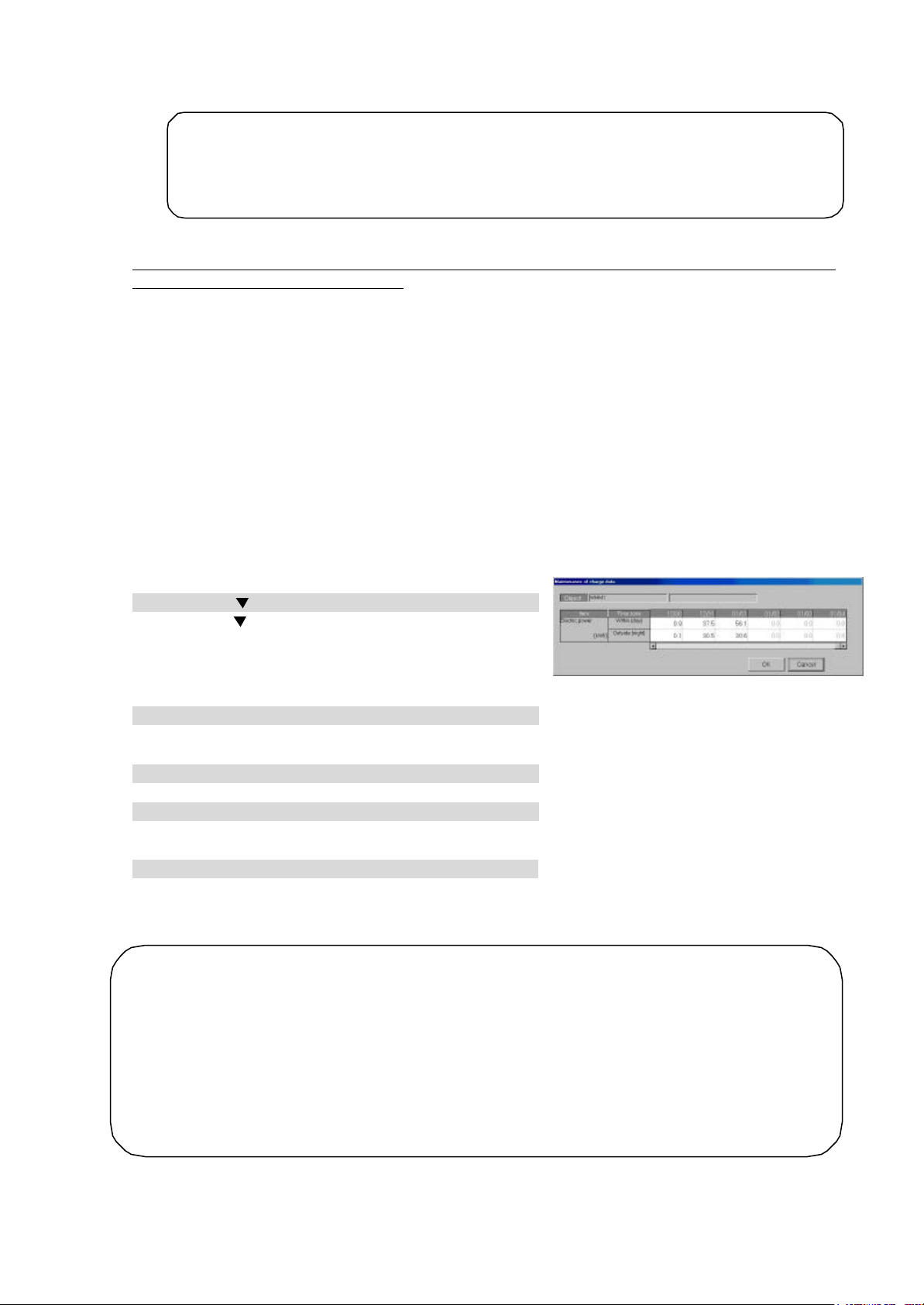
59
3) When the integration has already been made, select Recalculation to settle the charge for the
50A
50A is replaced, it is necessary to
conditioning charge after recalculation.
However, only watt hour units’ watt hour meters are the object. The corrected watt hour meter data
The proportional division electric power displayed in red is changed to maintenance (blue) and
conditioning charge results. (However, all the electric power
accounts term must be maintained.)
Data Display Colors]
Outside (night) : Off hours
month concerned.
<Maintenance example>
Note:
• It is necessary to perform the charge data maintenance on the date appointed for Grepair, after the next day, when the G-50A is replaced.
• Since the data cannot be fully corrected when the Gperform a special correction during failure.
Example of “Maintenance of charge data” during G-50A failure (proportionally divided electric power
charge (With RS -485 WHM connection))
1) Correct the apportioned electric power (during failure) to “0”, by which the value is changed to blue.
* Including appointed day of repair
2) Select and correct the failure period correction method from the following plans:
Plan : Use of average value for one week before failure
Calculate the power used during the failure period proportionally by percentage
using the average value for one week before the failure as the apportioned electric
power for a day, and input it as apportioned electric power for the repair date.
3) When the integration has already been made, select Recalculation to settle the charge for the
month concerned.
9.2.4 Watt Hour Meter Data Maintenance
This data may be changed. Follow these steps to display watt hour meter data broken down by regular
hours and off hours.
Maintaining watt hour Meter Data
[Procedure]
1) Click the “
When the “
charging data maintenance screen is clicked, all the watt
hour meters are displayed. Selecting the watt hour meter
you want to display and clicking the [Meter Maintenance]
button displays the watt hour meter maintenance screen.
2) Select the watt hour meter data.
Select the cell of the data to be changed (regular hours,
off hours). The cursor appears in that cell.
3) Make changes to the data.
Enter the changes to the data (for each time slot).
4) Repeat steps 1) to 3).
Repeat these steps to make changes to the part to be
changed.
5) Click [OK] button.
When done with these settings, click the [OK] button.
* If the [Cancel] button is clicked, the settings are interrupted and the screen returns to the initial
window.
Note:
• Corrected watt hour meter data will appear in the airdoes not appear at indoor units or watt hour meters connected to indoor units.
• The data for that day may not be correct if there was an abnormality on the previous day.
For example, when the previous day was abnormal, it may be forwarded to the next day.
•
recalculated and appears in the airdisplayed in red in the air-conditioning charge settlement-of-
• This function cannot be used for Without WHM connection proportionally divided electric charge.
” button and select a watt hour meter.
” button in the watt hour meter field in the
Watt Hour Meter Maintenance screen
[Watt Hour Meter
Black: Normal
Red : Abnormal
Blue : Maintenance
Gray : No data
[Time zone]
Within (day) : Regular hours
Page 63

60
Even if the operation amount data is monitored, it may not be executable in some cases due to the
50A and PC forward
mount data is monitored by the system (2000 units) for one month, it takes
Charge Data Maintenance screen
This screen can be used to verify the connection to
ue may have a time
WHM
.
of the
9.2.5 Verify Test Operation of Watt Hour Meter
Follow these steps to display the watt hour meter monitor.
Watt hour Meter Monitor Function
[Procedure]
1) Select the watt hour meter.
From the Charge Data Maintenance screen, select the
meter to monitor using the “” button.
2) Click [ Present Value Monitor] button.
Click the [Present Value Monitor] button. The Watt Hour
Meter Current Integrated Value screen appears for the
selected meter.
3) Click [OK] button.
When finished viewing these values, click the [OK]
button.
When the [Monitor] button is clicked, the watt hour meter
integrated value is monitored again.
Note:
•
the watt hour meters.
• The test operation integrated val
lag of 10 seconds to 2 minutes.
• This function cannot be used for Without
connection proportionally divided electric charge
• WHM test operation can be performed at the
Management screen also. Refer to section 8.5
Management manual.
Watt Hour Meter Current Integrated Value screen
WHM No. select box
9.3 Operation Amount Data Monitoring
When the operation amount data is monitored, it is possible to read the operation amount data for the
indoor unit provided for each G-50A.
<Description of function>
The system monitors the operation amount for the indoor unit from all the G-50A units to calculate the
proportionally divided power charge at 4:05 and after every day. (Operation amount of indoor unit:
capacity save ratio, FAN operation time, thermo-ON time, subsidiary heater operation time)
The proportional division is not calculated properly when the system is unable to monitor because the
power of the PC that the integrated centralized control software (TG -2000A) operates on is turned off,
the PC is defective, or the LAN circuit or hub with the G-50A is defective. (The calculation result is
correct, however, as the forwarded calculation is executed after the repair on the next day or at a later
time, but the calculation result is displayed in red as an error (red).)
Because of the reasons shown above, the Operation amount data monitor function is used to monitor the
operation amount data as a guideline (cannot be monitored) with the date designated using the charge
data maintenance described in 9.2 or the charging remedy described in 9.5 when the maintenance of the
proportional division parameter value or the apportioned electric power is performed.
<Supplement> The G-50A retains the data for the last 62 day s.
<Caution>
following reasons:
• When the data has not accumulated due to a power shutdown for over 24 hours of the G-50A
• When the data has not accumulated due to setting the time/date of the Gby over 24 hours
• When the G-50A is replaced due to G-50A failure
When the operation a
approximately one hour.
Page 64

61
Monitoring operation amount data
2000A is output unchanged. Contact us separately for the data
ON time, and subsidiary
, it is
The monitor of the operation amount data is intended for all indoor units for the object day, in
e written over the PC database on which the integrated centralized control
Since the monitor of the operation amount data requires time, wait for a moment until the
Even if the operation amount data monitor is executed, it cannot use the results for the
Maintenance of
screen even if the
operation amount data is gathered using this function, but upon the output of the charge
Operation amount data monitor
[Procedure]
1) Click [Operation amount data monitor] icon.
Click the [Operation amount data monitor] icon of the
maintenance group in the initial window. The operation
amount data monitoring screen appears.
2) Set the interval to be monitored.
Use click and the “/” buttons to set the interval the
running data held by the G-50A is to be monitored.
* Numbers can be manually input from the keyboard.
3) Click [OK] button.
When setting of the operation amount data monitoring interval is complete, click the [OK] button. The
operation amount data monitor confirmation screen
appears.
* If the [Cancel] button is clicked, the settings are
interrupted and the screen returns to the initial
window.
4) Click [OK] button.
Confirm the monitoring interval at the operation amount
data monitor confirmation screen. After confirmation,
click the [OK] button. If it is determined automatically
that the monitor-prohibit time is applicable.
When it is out of the prohibited time range, the
operation amount data monitor is started and the
message "Please wait a moment" is displayed on the
screen.
After the monitoring is terminated, the screen returns to the initial window.
Note:
•
which the contents ar
software (TG -2000A) operates. Monitor only the necessary date.
•
monitor is terminated.
• Monitor the data for the last day after 7:00.
•
recalculation of proportionally divided power charges. In this case, use the “
charge data” shown in 9.2 or the “Charging remedy ” shown in 9.5.
• Note that the data is not reflected in the “Maintenance of charge data”
parameter data.
Operation amount data monitoring screen
confirmation screen
9.4 Charge Parameter Output
This function is used to output the operation amount data (integrated capacity save ratio of indoor unit,
integrated FAN operation time, integrated thermo-ON time, (integrated subsidiary heater operation time))
and charge parameters to the file.
Note:
• The value stored in PC of TGgeneration method and other information.
* The values of the capacity save ratio, FAN operation time, thermo-
heater operation time are integrated values. When the value exceeds “999999”
returned to “000000”.
• The file output is executed for each G-50A.
Page 65

62
Output the operation amount data, which is the charge parameters, to the file.
button is
integrated value is left
[ Procedure]
1) Select [charge parameter output] menu.
Select the [charge parameter output] located in the
[Tool] menu in the initial window where the charge
G-50A select button
Output term setting
Output file name setting
parameter output screen is displayed.
* Note that this screen cannot be selected in the
Management screen.
2) Select the G-50.
When the “” button for selecting the G-50A is
clicked, the G-50A connected is displayed. Select
the G-50A to be output.
3) Set the interval.
Use the “/” buttons to set the year, month, and
day of the objective interval. An interval from the
previous day to 122 previous days can be set.
* The setting is executable regardless of whether the
data for the date concerned exists or not.
4) Set the file output destination.
Charge parameter output (set -up) screen
Set the file output destination folder. An existing folder
can be selected by clicking the [Refer] button.
Note:
• When a nonexistent folder is described as the file output destination and the [Save]
clicked, the file is saved by creating a new folder.
5) Set the save filename and click the Output button.
After setting the output destination and fi le name, click the [Output] button. The file is saved. After
finishing, this screen closes.
* Click the [Cancel] button to return to the Initial window.
<Output file data format>
The data format is CSV format. Data is output in ascending order.
A sample that uses MS-EXCEL to fetch an output file is shown here.
Note:
• When within a time
(daytime)/outside (night)
is not set, each
integrated value is
assumed to be (daytime)
and the (night) value
does not increase.
• When the integrated
value does not exist,
“-99” is set or the
Output file Excel fetch screen (sample)
blank.
9.5 Charging Remedy
Performing charging remedy
When charge apportioning was not performed (electric power not apportioned) due to watt hour meter
failure or data was destroyed by HDD failure, the air-conditioning charge can be easily computed by
using this remedial function.
Page 66

63
9.5.1 Preparing to perform charging remedy
conditioning charge. It cannot recover to
conditioning charge including the
ê
<Remedial a
pportioning interval>
accounts term
Settlement-of
accounts day
Settlement-of
Remedial apportioning simply apportions the entire
un-apportioned part and calculated the air- conditioning
charge using the normal apportioning data. For remedial
apportioning,
Failure generation
Failure recovery
ó
• Settlement -of-accounts term
• Apportioning interval
• Total billing air-conditioning charge
• Failure day watt hour meter integrated value
Normal Normal
Normal
apportioning +
Remedial
apportioning
+ apportioning
• Operation data monitoring
must be prepared or performed.
To perform the charging remedy, the items for each assumed case are shown below. V shows that the
remedy is required.
Item
Settlement-ofaccounts term
Remedial
apportioning
interval
Total billing
amount
Preparation
Wa tt hour meter
integrated value
for failure day
Operation amount
data monitoring
att hour
meter failure
(Monitoring
impos sible)
V V V V V Essential
V V V V V Essential
V V V V V *1
(V)
*2
V V V See sec.
HDD failure
(no backup)
Assumed case
HDD failure
(backup)
V
Computer
crash
System
information
setting error
*1 When there is one tariff, preparations are unnecessary.
*2 When replacing a watt hour meter, study the watt hour meter integrated value for the day the failure was
Remedial
apportioning
Implementation
thought to have occurred.
V V V V V See sec.
Note:
• This remedial apportioning simply calculates the airnormal apportioning.
• When the s ettlement -of-accounts term is one month, the airstandard charge can be calculated.
• When the operation amount data must be monitored, do it before remedial apportioning.
• This function cannot be used for Without WHM connection proportionally divided electric charge.
Settlement-ofaccounts end day
Normal
Remarks
9.3
9.5 .2
Page 67

64
9.5.2 Remedial apportioning setting screen
ccounts
Standard
apportioning
integrated
Multiple systems
.
Multiple systems
.
Multiple systems
.
Watt hour meter
e (Monitoring
Multiple systems
.
System information
Multiple systems
.
Assumed case
(no backup)
(backup)
failur
impossible)
setting error
V shows that the item must be set.
*1 When the settlement-of-accounts term is 1 month, the standard charge can be set.
*2 The power integrated Value may haVe to be set depending on the failure cause or the contents of the setting
(1) Check the items necessary for remedial apportioning.
When charging is not apportioned, the charging data is destroyed, etc., the air-conditioning charge can
be calculated by a simple method.
The items which must be set depend on the assumed case and the charging configuration. The table
below shows which setting items are required and are not required.
Charging
configuration
1 system V V *1 V V HDD failure
1 system V V *1 V HDD failure
1 system V V *1 V Computer crash
1 system V V *1 V V *2
1 system V V *1 V V *2
Settlementof-a
term
V V V *1 V V
V V V *1 V
V V V *1 V
V V V *1 V V *2
V V V *1 V V *2
Total air-
conditioning
charge
charge
Remedial
interVal
Power
Remark
Value
See sec
9.5.3
See sec
9.5.4
See sec
9.5.5
See sec
9.5.6
See sec
9.5.7
MoreoVer, when remedial apportioning including the standard charge is not performed, it cannot be reflected
in the air-conditioning charge result.
error.
(2) Set the remedial apportioning setting items.
(3)
[Procedure]
1) Click [Remedial apportioning setting] button.
Click the [Remedial apportioning] button in the initial
window. The remedial apportioning setting screen
appears.
2) Set the apportioning interval (Calculation).
Use click and the “/” buttons to set the interval to be
calculated by this remedial apportioning. An interval from
the previous day to the past 122 days can be set.
3) Set the total air-conditioning charge.
Set the settlement -of-accounts term total air-conditioning
charge. When the standard charge is included, the total
air-conditioning charge also includes the standard charge
for 1 month.
Remedial apportioning setting screen
*Numbers can be manually input.
4) Select the standard charge setting.
When the settlement-of-accounts term is 1 month, whether or not the standard charge is to be
included can be selected. Select [Include] or [Not include] with the option button.
5) Set the remedial apportioning interval.
Use click and the “
6) Set the power integrated value.
/
” buttons to set the remedial interval dates.
Displays the power integrated value at 00:00 hours of the remedial apportioning start day. (The
integrated value at 24:00 hours of the previous day.) Select the
field of the watt hour meter you want
to change with the mouse and set or change the power integrated value. The integrated value field of
the selected watt hour meter changes to a blue cell. When the integrated value data changes, the new
data is displayed in blue.
Page 68

65
conditioning charge does not have to be
e initial value is
accounts day, it recommends that this month
ing setting screen is clicked, the settings are
checked for errors. If there is an error in the set
edial apportioning calculation can be
cancelled by clicking the [Cancel] button in the
Remedial apportioning confirmation screen
Note:
• The initial integrated value is the interval for the previous month.
• When there is one electric power charge unit, the total airset and it is not displayed.
• [Include] standard charge can be selected only when the settlement-of-accounts term is 1 month.
• Set the power integrated value only when necessary. The power integrated valu
the value stored in the database. When there is no data, a blank is displayed.
• When the recovery day exceeds the settlement-ofand next month perform charging remedy.
• See the execution examples for each assumed case starting from section 9.5.3.
(3) Calculate remedial apportioning.
[ Procedure]
1) Click [OK] button.
When the necessary settings at the remedial appor- tioning
setting screen are complete, click the [OK] button. The
remedial apportioning confirmation screen appears.
2) Click [Yes] or [No] button.
Confirm remedial apportioning at the confirmation display
screen, and click the [Yes] button. The [Calculating] screen
appears.
Note:
• When the [OK] button in the remedial apportion-
contents, an alarm screen appears.
• Rem
Calculating screen.
• Remedial calculation takes several minutes.
Calculating screen
When there is an error in the remedial apportioning setting, a setting error warning message like that
shown below is displayed.
Alarm display 1
Alarm display 2
(4) Remedial apportioning calculated result display
At the end of remedial apportioning calculation, the remedial apportioning result screen appears.
Apportioning conditions
display
Remedial air-conditioning
charge display
Remedial apportioning result screen
Output button
Count save button
Back button
End button
Page 69

66
[Description of displays and buttons]
ted value, the data for the preceding month’s
accounts day because
Portion for month before last (normal)
Operation amount data monitoring screen
Day before recovery day
(1) A pportioning conditions display
Displays the counted and remedially apportioned conditions.
(2) Remedial air-conditioning charge
Displays the remedied air -conditioning charge calculated result in block and watt hour meter units.
Block units display is the remedial apportioning interval reference value.
(3) Output button
The remedial apportioning air-conditioning charge result can be output to a printer or file.
(4) Calculation save button
When the remedial apportioning air-conditioning charge result is the same as the calculated result
(including the standard charge), it can be written over the air-conditioning charge result in month units.
(5) Back button
Returns to the remedial apportioning conditions setting screen.
(6) End button
Ends the remedial apportioning screen.
9.5.3 Remedy when personal computer HDD fails (no backup)
The following describes the remedy when the personal computer HDD failed and the charging data was lost.
1) HDD recovery
Recover the personal computer HDD by replacement, etc. and install the necessary OS.
2) TG-2000A installation
Install TG -2000A MSDE, database and this program.
* Refer to the setup method and install.
3) System configuration and charging system restoration
Recover the system information by resetting the
air-conditioning system configuration, charging system,
etc.
4) Run the operation amount backup monitor.
Monitor backup of the operation amount before the recovery
day. Set the interval from the preceding month’s count end
day to the day before the recovery day.
Start day Failure Recovery Now End day
ê ó ˜
Monitor interval
Count (1 month)
Note:
• Operation amount data backup monitoring for the failure day is also possible.
• Since the operation amount data is the integra
count end day must also be monitored.
5) Wait until the day after the settlement -of-accounts day .
Continue normal operation up to the day after the settlement -of-accounts day.
Note:
• The system operates normally up to the day after the settlement-ofremedial apportioning is performed for one month.
6) Start remedial apportioning.
Start remedial apportioning by clicking the [Remedial apportioning] button in the initial window. This is
described with the time series example below.
Remedial interval
ê ó ˜
Portion for last month (remedial)
Failure Recovery Now
Preceding month’s count end day.
Current value
Page 70

67
accounts day. However,
. Remedial
apportioning can begin two days after the recovery day. (Only when the day after the recovery
accounts term is one
month and includes a standard charge, set the
charge including this
When there is one power charge (no time
conditioning charge does
recovered from an HDD failure and normal
Note:
• Perform remedial proportioning from the day after the settle-ofexcept when it is different from the normal settlement -of-accounts term
day was normally charged.)
7) Settlement -of-accounts term setting
Set the settlement-of-accounts term (start day and
end day) at the remedial apportioning setting screen.
The initial value is the settlement -of-accounts term of
the previous month.
8) Total air-conditioning charge setting
Set the total air-conditioning charge for the settlement-
of-accounts term.
Note:
• When the settlement-oftotal air-conditioning
standard charge.
•
setting), the total airnot have to be set. This item appears in gray.
9) Include/Not include standard charge setting
When the settlement -of-accounts term is one month, [Include] or [Not include] standard charge can
be selected. Set whether or not the standard charge is to be included.
10) Remedial interval setting
Set the remedial apportioning interval. The remedial start day is the settlement -of-accounts start day
and the remedial end day is the settlement -of-accounts end day.
Note:
• “Recovery day” is the day the system was
operation was restarted.
11) Watt hour meter integrated value setting
Set the watt hour meter integrated value of each watt
hour meter from the air-conditioning charge result (watt
hour meter) for the month before last. The watt hour
meter calculated result for the month before last is the
watt hour meter integrated value for the last day. Use
that value.
The watt hour meter integrated value for all the watt hour meters must be corrected and input. When
the integrated value data changes, the display turns blue. The initial value before correction and input
is a blank display.
When setting of the remedial apportioning screen is complete, perform section 9.5.2 “(3)
Calculate remedial apportioning”.
Remedial apportioning setting window
Watt hour meter air-conditioning charge result
9.5.4 Remedy when personal computer HDD fails (backup)
The following describes the remedy when the computer HDD fails and the charge data is backed up.
1) HDD recovery
Recover from personal computer HDD failure by replacing the HDD, etc. and install the necessary OS.
2) TG-2000A installation
Install TG-2000A MSDE, database, and this program. Refer to the setup method and install.
3) System configuration and charging system restoration
Install the database backing up the air conditioning system configuration, charging system, charging
data, etc.
Note:
• For the specific procedure, consult your distributor or sales company.
Page 71

68
4) Operation amount backup monitoring
up day must
also be monitored.
accounts day because
However, except
accounts term. Remedial apportioning can
begin two days after the recovery day. (Only when the day after the recovery day was normally
accounts term is
one month and includes a standard charge,
When there is one power charge, the total
conditioning charge does not have to be
Now
Portion for month before last (normal)
End day
Operation amount data monitoring screen
Day before recovery day
Preceding month’s count end day.
Monitor backup of the operation amount from the backup
day to the recovery day. Set the start day as the backup
day and the end day as the day before recovery day.
Start day Backup Failure Recovery Now
¢ ê ó ˜
Monitor interval
Count (1 month)
Note:
• Operation amount data backup monitoring for the failure day is also possible.
• Since the operation amount data is the integrated value, the data for the back-
5) Wait until the day after the settlement-of-accounts day .
Continue normal operation up to the day after the settlement -of-accounts day.
Note:
• The system operates normally up to the day after the settlement-ofremedial apportioning is performed for one month.
6) Start remedial apportioning.
Start remedial apportioning by clicking the [Remedial apportioning] button in the initial window. This is
described with the time series example below.
Remedial interval
Backup Failure Recovery
¢ ê ó ˜
Portion for last month (remedial)
Note
• Perform remedial proportioning from the day after the settle-of-accounts day.
when it is different from the normal settlement -of-
charged.)
7) Settlement -of-accounts term setting
Set the settlement-of-accounts term (start day and
end day) at the remedial apportioning setting screen.
The initial value is the settlement-of-accounts term of
the previous month.
8) Total air-conditioning charge setting
Set the total air-conditioning charge for the settlement-
of-accounts term.
Note:
• When the settlement -ofset the total air-conditioning charge
including this standard charge.
•
airset. This item appears in gray.
Remedial apportioning setting window
9) Include/Not include standard charge setting
When the settlement-of-accounts term is one month, [Include] or [Not include] standard charge can
be selected. Set whether or not the standard charge is to be included.
10) Remedial interval setting
Set the remedial apportioning interval. The remedial start day is the backup day and the remedial end
day is the recovery day.
Current value
Page 72

69
“Recovery day” is the day the system was recovered from a HDD failure and is the day
rtioned normally for the day before the remedial apportioning start
day, change the remedial apportioning start day to the day after the day normally charged
lue field, there is no data in
accounts day. However, except
accounts term. Remedial apportioning can
(Only when the day after the recovery day was normally
erated by a computer crash can be
Note:
•
normal operation was restarted.
• When charge is not appo
before the backup day.
11) Watt hour meter integrated value setting
The value at 24:00 hours of the day before backup is displayed at the watt hour meter integrated
value of each watt hour meter. The watt hour meter integrated value does not have to be corrected.
Note:
• When a value is not displayed in the watt hour meter integrated va
the database. Since a setting error is possible, check the remedial apportioning start day.
• Normal charge apportioning is necessary for the day before backup.
When setting of the remedial apportioning screen is complete, perform Section 9.5.2 “(3)
Calculate remedial apportioning”.
9.5.5 Apportioning method when computer crashes
The following describes the apportioning method when the computer crashes and the charging data is
abnormal and apportioning (un-apportioned) cannot be performed.
Note:
• Whether or not un-apportioning of charging data was gen
checked at the “Charging data maintenance” screen.
• When the charging data is not apportioned, this remedial apportioning is unnecessary.
This is described with the time serial example below.
Start day Crash Recovery End day Now
¢ ó ˜
Monitor interval
Remedial interval
Count (1 month)
1) Computer down time chec k
Check the time the computer was shut down at the “Charging data maintenance” screen. When
nothing exists in the charging data, the numbers are displayed in gray.
2) Operation amount backup monitoring
Monitor backup of the operation amount from the day the computer crashed to the day it was recovered.
Set the start day as the computer crash day and the end day as the day before recovery day.
Note:
• Operation amount backup monitoring can be performed for the recovery day also.
3) Start remedial apportioning.
Start remedial apportioning by clicking the ] Remedial apportioning] button in the initial window.
Note:
• Begin remedial apportioning from the day after the settlement -ofwhen it is different from the normal settlement -ofbegin two days after the recovery day.
charged.)
4) Settlement -of-accounts term setting
Set the settlement -of-accounts term (start day and end
day) at the remedial apportioning setting screen. The
initial value is the settlement-of-accounts term of the
previous month.
5) Total air-conditioning charge setting
Set the settlement-of-accounts term total air- conditioning
charge.
Remedial apportioning setting window
Page 73

70
accounts term is one month and includes a standard charge, set the
conditioning charge does not have to be set. This
When the charge for the day before the apportioning start day is not apportioned normally,
the day after the first day charged normally before the
value field, there is no data in
accounts day because remedial
accounts day. However,
accounts term. Remedial
apportioning can begin two days after the recovery day. (Only when the day after the recovery
Portion for last month (remedial)
Remedial apportioning
Note:
• When the settlement -oftotal air-conditioning charge including that standard charge.
• When there is one power charge, the total airitem cannot be set.
6) Include/Not include standard charge setting
When the settlement -of-accounts term is one month, [Include] or [Not include] standard charge can
be selected. Set whether or not the standard charge is to be included.
7) Remedial interval setting
Set the apportioning interval. The apportioning start day is the computer crash day and the
apportioning end day is the recovery day.
Note:
•
change the apportioning start day to
computer crashed.
8) Watt hour meter integrated value setting
The value at 24:00 hours of the day before the computer crashed is displayed in the watt hour meter
integrated value of each watt hour meter. The watt hour meter integrated value does not have to be
corrected.
Note:
• When a value is not displayed in the watt hour meter integrated
the database. Since there may be a setting error, check the remedial start day.
• The charge for the day before the computer crashed must be apportioned normally.
When setting of the remedial apportioning screen is complete, perform Section 9.5.2 “(3)
Calculate remedial apportioning”.
9.5.6 Remedy when watt hour meter fails (monitoring impossible)
The following describes the remedy when a watt hour meter fails and the charging data is abnormal and
is not apportioned.
1) Recovery from watt hour meter failure
Locate and remove the cause of the watt hour meter failure. The cause of the failure may be an open
transmission line, CT failure, or failure of the watt hour meter itself.
2) Wait until the day after the settlement -of-accounts day .
After recovery, continue normal operation until the day after the settle-of-accounts day.
Note:
• Operate normally up to the day after the settlement -ofapportioning is performed for one month.
3) Start remedial apportioning.
Start remedial apportioning by clicking the “Remedial apportioning” icon in the initial window. This is
described by the time series example below.
Failure Recovery Now
ê ó ˜
Portion for month before last (normal)
Note:
• Perform remedial proportioning from the day after the settle-ofexcept when it is different from the normal settlement -of-
day was normally charged.)
Page 74

71
4) Settlement -of-accounts term setting
accounts term is one
standard charge, set the
conditioning charge including this
When there is one power charge, the total
charge does not have to be set.
This item appears in gray.
day” is the day watt hour meter monitoring was recovered and is the day that
When the day before the remedial start day was not charge apportioned normally, change the
Set the settlement -of-accounts term (start day and end
day) at the remedial apportioning setting screen. The
initial value is the settlement-of-accounts term of the
previous month.
5) Total air-conditioning charge setting
Set the total air -conditioning charge for the settlementof-accounts term.
Note:
• When the settlement -ofmonth and includes a
total airstandard charge.
•
air-conditioning
Remedial apportioning setting window
6) Include/Not include standard charge setting
When the settlement -of-accounts term is one month, [Include] or [Not include] standard charge can
be selected. Set whether or not the standard charge is to be included.
7) Remedial interval setting
Set the remedial apportioning interval. The remedial start day is the failure generation day and the
remedial end day is the recovery day.
Note:
• “Recovery
normal operation was started.
•
remedial start day to the day after the day normally charged before the failure day.
8) Watt hour met er integrated value setting
The value at 24:00 of the day before the failure day (value for 00:00 of the failure day) is displayed at
the watt hour meter integrated value of each watt hour meter.
Failure cause: watt hour meter transmission line open (When watt hour meter counts normally.)
The watt hour meter integrated value does not have to be corrected.
Failure cause: watt hour meter failure or CT failure (When watt hour meter does not count normally)
Only the watt hour meter integrated value of the fail ed watt hour meter must be corrected. Refer to
the watt hour meter integrated value for the week before the failure and study the electric power
consumption for the remedial interval.
Examples 1 and 2 study the power consumption for the three days from the failure day (00:00) to
the day after recovery (00:00) and calculate the power integrated value for 00:00 of the failure day
(24:00 of the day before the failure day), with the integrated value for the day after recovery as the
standard.
The power integrat ed value is corrected to the calculated value for 00:00 of the failure day.
Ex. 1) Remedial interval power consumption study (Remedial interval = 3 days)
(00:00 value) Units: kWh
Integrated
value
Consumption 100 110 90 120 160 20 100 300
* The average day’s power consumption and remedial interval power consumption are assumed to be 100kWh and
300kWh , respectively.
The power integrated value is set at “950-300=650” kWh.
7 days
before
200 300 410
6 days
before
5 days
before
4 days
before
50
0
3 days
before
620 780 800 900 … 950
2 days
before
1 day
before
Failure
day
…
Day after
recovery
Page 75

72
Ex. 2) Remedial interval power consumption study (Remedial interva l = 3 days)
It may not be possible to remedy a setting error even by remedial apportioning depending on the
accounts day because
accounts day. However,
accounts term. Remedial
after the recovery
accounts up to the day
y integrated value by
The indoor unit operation amount can also be referenced in watt hour meter integrated value
he average value can also be studied from the monthly units watt hour
conditioning charge result. It is recommended that the calculation method suited to the
egative value, set the value calculated
Portion for last month (remedial)
Remedial interval
Integrated
value
Consumption 100 110 90 120 160 20 100 300
* The average day’s power consumption and remedial interval power consumption are assu med to be 100kWh and
300kWh , respectively.
The power count value is set at “5-300+9999+1=9705” kWh.
(Watt hour meter maximum integrated value: 9999 Minimum integrated value: 1)
7 days
before
200 300 410 500 620 780 800 900 … 5
6 days
before
5 days
before
4 days
before
3 da ys
before
2 days
before
1 day
before
Note:
• The watt hour meter integrated value for each date can be displayed b
changing the remedial apportioning start day.
• The day before the failure day must be charge apportioned normally.
•
calculation and study. T
meter airsystem conditions be used.
• When the calculated watt hour meter integrated value is a n
integrated value + watt hour meter maximum integrated value + minimum integrated value.
When setting of the remedial apportioning screen is complete, perform Section 9.5.2 “(3)
Calculate remedial apportioning”.
9.5.7 Remedy for system information setting error
The following describes the remedy when a system information (system configuration, charging system,
etc.) setting error was found.
Note:
•
type of system setting error.
• This remedial apportioning cannot be used for system configuration and other changes.
1) System setting error recovery
Find and correct the system setting error. Setting errors include group setting, block setti ng, watt hour
meter and unit correspondence setting, etc.
Maintenance tip
• Before system setting error recovery, perform interval settlement-ofbefore the setting error and output the result.
2) Continue operation until the day after the settlement -of-accounts day .
Continue normal operation up to the day after the settlement -of-accounts day.
Note:
• Normal operation is continued up to the day after the settlement-ofremedial apportioning is performed for one month.
3) Start remedial apportioning.
Start remedial apportioning by clicking the [Remedial apportioning] button in the initial window. This is
described by the time series example below.
Setting error recovery Now
ó ˜
Note:
• Begin remedial apportioning from the day after the settlement -ofexcept when it is different from the normal settlement -ofapportioning can begin two days after the recovery day. (Only when the day
day was normally charged.)
(00:00 value) Units: kWh
Failure
day
…
Day after
recovery
Page 76

73
4) Settlement -of-accounts term setting
accounts term is one
month and includes a standard charge, set the
conditioning charge including that
power charge, the total
conditioning charge does not have to be
“Recovery day” is the day the system recovered from a system setting error and normal
alue for each date can be displayed by changing the
value
tion and study. It is recommended that the calculation method suited to the system
value is a negative value, set the value
calculated integrated value + watt hour meter maximum integrat ed value + minimum
Set the settlement -of-accounts term (start day and end
day) at the remedial apportioning setting screen. The
initial value is the settlement -of-accounts term of the last
month.
5) Total air-conditioning charge setting
Set the total air -conditioning charge for the settlementof-accounts term.
Note:
• When the settlement-oftotal air-
standard charge.
• When there is one
airset. This item appears in gray.
6) Include/Not include standard charge setting
When the settlement -of-accounts term is one month, [Include] or [Not include] standard charge can
be selected. Set whether or not the standard charge is to be included.
7) Remedial interval setting
Set the remedial apportioning interval. The remedial start day is the settlement -of-accounts day and
the remedial end day is the system setting error recovery day.
Note:
•
operation started.
8) Watt hour meter integrated value setting
The value at 24:00 hours of the day before the count start day is displayed in the watt hour meter
integrated value of each watt hour meter.
Setting error: When watt hour meter and unit wiring connection match
The watt hour meter integrated value does not have to be corrected.
Failure cause: When watt hour meter and unit wiring connection is wrong
Refer to the indoor unit operation amount and calculate and study the remedial interval power
consumption for each watt hour meter. Only the watt hour meters where the watt hour meter and
unit wiring connection is wrong have to be studied.
Note:
When setting of the remedial apportioning screen is complete, perform Section 9.5.2 “(3)
Calculate remedial apportioning”.
• The watt hour meter integrated v
remedial apportioning start day.
• The day before the failure day must be charge apportioned normally.
• The indoor unit operation amount can also be referenced in watt hour meter integrated
calcula
conditions be used.
• When the calculated watt hour meter integrated
Remedial apportioning setting window
Page 77

10. Error Code List
(1) Air-conditioning unit error codes
The following is a list of the error codes and their meaning.
0110 “Equipment abnormality 1 ”
0120 “Equipment abnormality 2 ”
0403 “Serial transmission trouble”
0900 “Test run”
1000 “Ref.cycle abnormality”
10*0 “Ref.cycle abnormality in line *”
11** “Ref.cycle temperature abnormality - Common operand: **”
12** “Ref.cycle temperature abnormality allowance - Common operand: **”
13** “Ref.cycle pressure abnormality - Common operand: **”
14** “Ref.cycle pressure abnormality allowance - Common operand: **”
1500 “Ref.cycle not operate due to overcharge”
1501 “Ref.cycle not operate due to undercharge” (/compressor shell temperature abnormality )
1502 “Ref.cycle not operate due to liquid back”
1503 “Ref.cycle not operate due to coil frost”
1504 “Ref.cycle not operate due to overheat protection”
1505 “Ref.cycle not operate due to compressor vacuum operation protection/refrigerant low
temperature abnormality”
1506 “Ref.cycle not operate due to refrigerant pump abnormality”
1559 “Oil balance circuit abnormality”
1600 “Ref.cycle - Preliminary overcharge refrigerant trouble”
1601 “Ref.cycle - Preliminary lacked refrigerant trouble”
1605 “Ref.cycle - Preliminary suction operation protection”
1607 “Ref.cycle - Preliminary C S circuit closed detection abnormality”
1608 “Ref.cycle - Preliminary control valve abnormality”
1659 “Ref.cycle - Preliminary oil balance circuit abnormality”
2000 “Water system abnormality” (Pump interlock abnormality)
20*0 “Water system abnormality in line *”
21** “Water system temperature abnormality - Common operand: **”
22** “Water system temperature abnormality allowance - Common operand : **”
23** “Water system pressure abnormality - Common operand: **”
24** “Water system pressure abnormality allowance - Common operand: **”
2500 “Water system not operate due to water leak”
2501 “Water system not operate due to water supply suspension”
2502 “Water system not operate due to drain pump abnormality”
2503 “Water system not operate due to drain sensor abnormality /float switch function”
2504 “Water system not operate due to liquid level abnormality”
2505 “Water system not operate due to cool water valve abnormality”
2506 “Water system not operate due to warm water valve abnormality”
2600 “Water system operation restricted due to water leak”
2601 “Water system operation restricted due to water supply suspension/humidifier water supply
suspension”
2602 “Water system operation restricted due to drain pump abnormality”
2603 “Water system operation restricted due to drain sensor abnormality”
2604 “Water system operation restricted due to liquid level abnormality”
3152 “Air system - C ontrol box temperature abnormality”
3252 “Air system - Preliminary control box temperature abnormality”
3600 “Air system operation restricted due to filter clogging”
3601 “Air system operation restricted due to filter maintenance”
3602 “Air system operation restricted due to damper position detecting abnormality”
37** “Air system operation humidity abnormality allowance - Common operand: **”
4000 “Electric system abnormality”
40*0 “Electric system abnormality in line *”
4100 “Electric system not operate due to overcurrent shut-off”
4101 “Electric system not operate due to overcurrent protection”
4102 “Electric system not operate due to open phase”
4103 “Electric system not operate due to reversed phase/open phase”
74
Page 78

4104 “Electric system not operate due to electric leak”
4105 “Electric system not operate due to short circuit”
4106 “Electric system not operate due to self power supply OFF/power failure”
4107 “Electric system not operate due to overlord”
4108 “Electric system not operate due to overlord protection/OCR51C”
4109 “Electric system not operate due to OCR51F”
4110 “Electric system not operate due to high voltage part”
4111 “Electric system not o perate due to bus current”
4112 “Electric system not operate due to coil overheat 49°C”
4113 “Electric system not operate due to heater overheat”
4114 “Electric system not operate due to fan controller abnormality”
4115 “Electric system not operate due to power supply synchronism abnormality”
4116 “Electric system not operate due to motor abnormality/speed abnormality”
4121 “Electric system not operate due to trouble in equipment to which a measure against higher
harmonics is taken”
4158 “Electric system - Preliminary overcurrent protection/OCR51C”
4171 “Electric system - Preliminary trouble in equipment to which a measure against higher
harmonics is taken”
4200 “Inverter abnormality”
420* “Inverter abnormality - Inverter No.: *”
4210 “Inverter overcurrent s hut-off”
421* “Inverter overcurrent shut-off - Inverter No.: *”
4220 “Inverter bus voltage insufficiency”
422* “Inverter bus voltage insufficiency - Inverter No.: *”
4230 “Inverter radiating thermostat abnormality”
423* “Inverter radiating thermostat abnormality - Inverter No.: *”
4240 “Inverter overcurrent (overload) protection”
424* “Inverter overcurrent protection - Inverter No.: *”
4250 “Inverter IPM/bus voltage abnormality”
425* “Inverter IPM abnormality *”
4260 “Inverter cooling fan trouble”
426* “Inverter cooling fan trouble - Inverter No.: *”
4300 “Inverter abnormality allowance”
430* “Inverter abnormality allowance - Inverter No.: *”
4310 “Inverter overcurrent shut-off allowance”
431* “Inverter overcurrent shut-off allowance - Inverter No.: *”
4320 “Inverter bus voltage insufficiency allowance”
432* “Inverter bus voltage insufficiency - Inverter No.: *”
4330 “Inverter radiating thermostat abnormality allowance”
433* “Inverter radiating thermostat abnormality allowance - Inverter No.: *”
4340 “Inverte r overcurrent protection abnormality”
434* “Inverter overcurrent protection abnormality - Inverter No.: *”
4350 “Inverter IPM abnormality allowance”
435* “Inverter IPM abnormality allowance *”
4360 “Inverter preliminary cooling fan trouble”
436* “Inverter preliminary cooling fan trouble - Inverter No.: *”
5000 “Sensor trouble”
50*0 “Sensor trouble in system *”
51** “Temperature sensor trouble - Sensor No.: **”
52** “Pressure sensor trouble - Sensor No.: **”
53** “Current sensor trouble - Sensor No.: **”
54** “Humidity sensor trouble - Sensor No.: **”
55** “Gas sensor trouble - Sensor No.: **”
56** “Air speed sensor trouble - Sensor No.: **”
57** “Limit switch trouble - Switch N o.: **”
58** “Sensor trouble - Sensor No.: **”
59** “Other sensors trouble - Sensor No.: **”
6000 “System abnormality”
6101 “System not operate due to abnormality - With response frame”
6102 “No answer back”
6500 “Communication error”
6600 “Communication error - Address duplicate”
6601 “Communication error - Polarity unsettled”
75
Page 79

6602 “Communication error - Transmission processor hardware error”
6603 “Communication error - Transmission line busy”
6604 “Communication error - No ACK (06H) (communication circuit error)”
6605 “Communication error - No response frame”
6606 “Communication error - Transmission processor communication error”
6607 “Communication error - No ACK return”
6608 “Communication error - No return of response frame”
6609 “Communication error”
6610 “Communication error”
6700 “Communication error - K-transmission abnormality”
6701 “Communication error - K-transmission error”
6702 “Communication error - K-address duplicate”
6750 “Communication error - K abnormality code PO”
6751 “K abnormality - Room temperature thermistor abnormality”
6752 “K abnormality - Indoor coil thermistor abnormality, Condensation temperature sensor
abnormality”
6753 “K abnormality - Transmit/receive error”
6754 “K abnormality - Drain sensor abnormality, Float switch function”
6755 “K abnormality - Drain pump abnormality”
6756 “K abnormality - Coil frost/overheat protection”
6757 “K abnormality - System error”
6758 “K abnormality - Outdoor unit trouble, Indoor/outdoor communication error”
6761 “K abnormality - Room temperature thermistor abnormality”
6762 “K abnormality - Indoor coil thermistor abnormality, Condensation temperature sensor
abnormality”
6763 “K abnormality - Transmit/receive error”
6764 “K abnormality - Drain sensor abnormality”
6765 “K abnormality - Drain pump abnormality”
6766 “K abnormality - Coil frost/overheat protection”
6767 “K abnormality - Outdoor unit trouble - Indoor/outdoor communication error”
6771 “K abnormality - High pressure abnormality, Low pressure abnormality”
6772 “K abnormality - Inner thermostat function, Discharge temperature abnormality, Shell
thermostat function, Overcurrent protection”
6773 “K abnormality - Radiator plate thermostat function”
6774 “K abnormality - Outdoor thermistor abnormality”
6775 “K abnormality - Pressure sensor abnormality, Indoor/outdoor communication error”
6776 “K abnormality - Overcurrent shut-off”
6777 “K abnormality - System error”
6778 “K abnormality - Normal”
6779 “K abnormality - Refrigerant overcharge, Abnormal voltage, Abnormal CT sensor”
6800 “Communication error - Other communication errors”
6801 “Communication error - V-control communication error”
6810 “Communication error - UR communication error”
6811 “Communication error - UR communication synchronism not recover”
6812 “Communication error - UR communication hardware error”
6813 “Communication error - UR communication status bit d etection error”
6820 “Other communication errors”
6821 “Other communication errors - Transmission line busy”
6822 “Other communication errors - No communication ACK”
6823 “Other communication errors - No response command”
6824 “Other communication errors - Receive data error”
6830 “Communication error - MA communication refrigerant address double setting error”
6831 “Communication error – No MA communication reception error”
6832 “Communication error – MA communication synchronism not recover”
6833 “Communication error - MA communication transmission/reception hardware trouble”
6834 “Communication error - MA communication start bit detection error”
7000 “System abnormality”
7100 “System abnormality - Total capacity error”
7101 “System abnormality - Capacity code error”
7102 “System abnormality - Connecting unit number excess”
7103 “System abnormality - Piping length setting error”
7104 “System abnormality - Floor height setting error”
7105 “System abnormality - Address setting over 254”
76
Page 80

7106 “System abnormality - Attribute setting error”
systems
error
conditioner unit
7107 “System abnormality - Distributor setting error”
7108 “System abnormality - Ref. system setting error”
7109 “System abnormality - Connection setting error”
7110 “System abnormality - Ref. system connection/connection data unsettled”
7111 “System abnormality - I/O connection equipment not connected/remote controller sensor
abnormality”
7112 “System abnormality - I/O type setting error”
7113 “System abnormality - Equipment unsettled”
7130 “System abnormality - Different unit model error”
7200 “System abnormality - Numeric values unsettled”
7201 “System abnormality - Numeric values unsettled”
Note:
• The error codes list all the codes. Error codes that are not displayed with some TG-2000A
are also listed.
(2) System error codes
The following is a list of the error codes and their meaning.
G-50A error
0003 “Communication error”
WHM error
0003 “Communication error”
Note:
• Displays the man-machine (integrated centralized control software TG-2000A), and G-50A
codes by a number up to 4 digits long. The meaning is different from that of the airerror codes.
77
Page 81

11.Setting Check List
function, it is necessary
11.1 Setting Check List
Follow a setting item check list according to each function you want to use.
Detail of function
Case 1 Manage groups by address
Case 2 Manage groups and blocks by name (shown by floor plan)
Case 3 Case 2 + Manage scheduling
Case 4 Case 3 + Manage air conditioner charging
Check the following items for the above cases.
Setting item Case 1 Case 2 Case 3 Case 4
User settings V V V V
Site name settings V V V V
Set number of G-50A V V V V G-50A
connection
setting
System
configuration settings
Monitoring
setting
Time settings V V V V
Password change V V V V
Option
Set G-50A IP address V V V V
Configure unit V V V V
Set cooling system V V V V
Set the Indoor unit groups V V V V
Set indoor units and ventilation
functions
Setup of unit model name V V V V
Set t he number of floors and floor
name
Create floor planes V V V V
Set the floors and G-50A units V V V V
Position and name group icons V V V V
Set blocks V V V V
Setting schedule (Year/Week) V V
Setting charge system V
WHM setting *1 V
Check initial settings of charge
system setting
V V V V
V V V V
V
*1: In charge collection without WHM connection, a setup is unnecessary.
Note:
• To use the optional annual/weekly schedule and charge (calculation)
• Change the password as required.
to register the license No. to the G-50A .
78
Page 82

11.2 Test Run Check
check, complete the test run checks of the systems under the
Test run check sheet
To make the check sheets easy to read, allocate 1 check sheet page for each installation floor unit or
central controller G-50A unit.
Note:
• Before carrying out a test run
control of the central controller G-50A .
• See Chapter 3 for details on site adjustment.
Once the initial settings have been carried out as prescribed by the section on field adjustment in this
manual, follow the order of testing prescribed by the test run check sheet and check the following
items: (1) to (4).
(1) Check operation start -up.
• Once the necessary information has been entered in the initial screen, advance to the control
screen.
• Check that the screen which indicates operation start -up is in progress appears.
• The time depends on the number of air conditioners that ar e connected. The operation start-up
should take between 10 to 20 minutes to complete.
• Check the display of each floor to make sure there is no error mark.
• If an error occurs, check the error history on the history screen.
(2) Man-machine on-off (on-off from the integrated centralized control software TG -2000A)
• Operate an air conditioner unit from the man-machine.
• Confirm the displays of the local remote controller, central controller G-50A, system controller
and man-machine indicate the air conditioner is operating.
• Carry out air conditioner operation in order of group, block, floor and entire building.
• If operation from the man-machine operated the wrong air conditioner, check the following
settings.
àPosition and name of group icon setting (S ee section 8.7.6)
àIndoor unit and ventilation group setting (See section 8. 6.5)
àBlock setting (See section 8. 7.7)
(3) Local remote controller on-off
* This step is only required when a local remote controller is connected.
• Operate the air conditioner unit from the local remote controller.
• Confirm the central controller G-50A and man-machine indicates that the air conditioner unit is
operating.
• On the man-machine display, check the floor screen, block screen and entire building screen
are correct.
(4) Central controller G-50A on-off
• Operate the air conditioner unit from the central controller G-50A .
• Confirm the local remote controller and man-machine indicates that the air conditioner unit is
operating.
• On the man-machine display, check the fl oor screen, block screen and entire building screen
are correct.
79
Page 83

A
50A
50A
Test run check s heet
Name of managed equipment Test operation procedure and check results
Floor G-50
IP
address
Unit
address
Unit
model
Group
address
Group
name
Block
name
Start-up
check
error
display
M /M on-off group units M /M on-off block units
LRC
display
G-
display
AC
status
LRC
display
Gdisplay
M/M: Man-machine G-50A: Central controller LRC: Local remote controller AC: Air conditioner unit
AC
status
80
Page 84

50A
50A
Date Tester
Test operation procedure and check results
M /M on-off Floor units M /M on-off Entire
G-
display
display
AC
status
display
LRC
building
G-50A
display
status
Local remote controller on-off Central controller G-50A on/off
AC
M -M display M -M display LRC
Floor Block Entire
G-
display
Floor Block Entire
building
LRC
display
building
81
Page 85

11.3 Charging Test Run Check
irst day before 4:00. If the air conditioner has been stopped
during the period from 0:00 to 4:00, it is possible to conduct the checking in two days.)
), fix the problem and
11:00
13:00
Test run period of air
12:00
14:00
Note:
• The charging test run check takes at least 3 days.
(Check the contents for the f
• Leave enough time for the transfer when carrying out the charging test operation.
• Carry out this check when system is modified while the system is up and running.
Flow of charging test run
Test item Comment
Day 1 (1) Check the charge setting details on the
man-machine
Day 2 (2) Check the meter values of the watt hour meter
(No. 1)
(3) Let the air conditioners run
* After checking the setting, allow
TG-2000A to operate as it was.
* Items (2) and (4) are performed
for charge calculation with WHM
connected.
(4) Check the meter values of the watt hour meter
(No. 2)
Day 3 (5) Check the results of charging division
(6) Check the settlement results
* When the check result is OK,
item (8) is performed.
(7) Decision check
(8) Change to actual operation setting
Man-machine: Personal computer for integrated centralized control software TG-2000A
11.3.1 Charging (No WHM connection) Test Run Check
Charging test run check sheet (Charging (No WHM connection))
Perform the charging test run check after the test run check is complete.
Follow the order of testing prescribed by the charging test run check sheet and check the following
items: (1) to (6).
Note:
• When the results do not conform to the decision standards outlined in (5
restart the check from (1).
(1) Check the charge setting details on the man-machine.
Write the charge setting details down on the charging test run check sheet.
Check the details of the data to ensure charging is operating correctly.
• Division mode selection (S ee section 8.9.2)
à Set the mode used
• Charge setting (See section 8.9. 9)
à Set the time using the with within/outside setting to perform the charging test run check.
(Same unit cost for the With daytime/nighttime setting, Without weekend charge setting,
and Without seasonal charge setting)
For the unit cost, set both within and outside to 10.
Execute the setting so that the test run time for the air conditioner is carried over both within
and outside.
Example)
conditioner
Outside Within Outside
• Settlement day setting (See 9.3 in Management).
à For charging test run check purposes, set it to the next day
• Charge block setting (See section 8.9.7)
à Set the charge block to be manipulated
* To set the charging block, (operation block) must be set. (See section 8.7.7)
Check the following details for each indoor unit.
• Addresses of the outdoor units in the same refrigerant system (See section 8. 6.4)
• Performance of indoor units (See section 8. 9.6)
82
Page 86

• Fan capacity (See section 8. 9.6)
Be sure to operate all air conditioners for over 2 hours on the next day when the integrated
they do not run for that length of
After the charging test run check, check the result of the print out of the settlement day
next settlement day or
uring charging test run, set the items shown below to the test run value. Set them to the
To make the check sheets easy to read, allocate 1 check sheet page for each installation floor unit or
G-50A unit.
Note:
• Always ensure the details of each setting are correct.
(Incorrect setting details will affect air conditioner charging.)
(2) Let the air conditioners run
Operate all the air conditioners from the man-machine (TG -2000A).
Check that all air conditioners are running and write it down on the charging test run check sheet.
Note:
•
centralized control software TG -2000A starts up. (When
time, the results will not pass the decision standards outlined in (5) Decision standards.)
• Record the air conditioner operation time.
(3) Check the results of charging division
Check the charge calculation parameter (within, outside) of all indoor units for the last day on the
charge calculation data maintenance screen, and enter it in the charge calculation operation check
sheet.
Note:
• Perform this on the day after the air conditioner running operation (charging test run).
Check after 7:15 on the next day.
(4) Check the settlement results
For charging test run, check the settlement results on the next day of air conditioner running
operation (the third day). The settlement results of the air -conditioning charge is printed or output to
the file. (Check after 05:10 on the next day. )
(5) Decision checks
Check that there is not any "0" values in the charge calculation parameter of the block.
Compare the time with the air conditioner running operation time (changed by minute), using the
charge data maintenance function to check that the value of the fan operation time (parameter
used) is less than the value of running operation time.
It is determined to be OK when the following conditions are all satisfied.
Condition (1): The value of the charge calculation parameter is not "0".
Condition (2): The fan operation time (parameter used) of the indoor unit is less than the
operation time (by minute) of the air conditioner.
When the decision check is NG, check the following contents to restore the necessary conditions.
• Charge calculation block setting (block setting)
• Indoor unit setting (capacity, fan capacity)
After restoring the necessary conditions, perform the charging test run again.
Maintenance Tip:
•
calculation for day 1.
• If the system is modified, always check the calculation results of the
one day after the change and 10 days after the change.
(6) Change to actual operation setting
After the charging test run check is completed, restore the regular field settings.
Note:
• D
value to be used.
83
Page 87

Charging test run check sheet
50A IP
Aux. heater
[Checking order
]
Item Division mode
selection
Charge setting Settlement
date setting
Indoor unit setting
contents
-
Check
Name of managed equipment
Floor G-
address
Unit
address
Group
address
Charge block
name
Indoor unit
performance
Fan
capacity
Comment
capacity *1
*1: This item is not used.
84
Page 88

Division mode
Seasonal
day
Comme
- - Air conditioner
Hour-operation
Check results
Operation
check
Total
[ Setting details check after test operation]
Item
Check
operation check
Outdoor unit charge
calculation parameters
Indoor unit charge
calculation parameters
Within Outside Check Within Outside Check
Charge setting
setting
Charge
calculation
reference
data
-
Within/
Outside
Weekend
Standard Weekend Seasonal
Charge division
Decision
results check
MEMO
Charge unit used
(top: within / bottom: outside)
Seasonal
standard
weekend
check
Settlement
check
Settlem
ent
setting
nt
85
Page 89

), fix the problem and
11:00
13:00
Test run period of air
12:00
14:00
11.3.2 Proportionally Divided Power Charge (RS-485 WHM connection) Test Run Check
Charging test run check sheet (proportionally divided power charge (RS-485 WHM connection))
Perform the charging test run check after the test run check is complete.
Follow the order of testing prescribed by the charging test run check sheet and check the following
items: (1) to (8).
Note:
• When the results do not conform to the judgment standards outlined in (7
restart the check from (1).
(1) Check the charge setting details on the man-machine console.
Write the charge setting details down on the charging test run check sheet.
Check the details of the data to ensure charging is operating correctly.
• Division mode selection (See section 8.9.2)
Set the mode used.
• Charge setting (See section 8.9.9)
Set the time using the with within/outside setting to perform the charging test run check.
(Same unit cost for the With daytime/nighttime setting, Without weekend charge setting,
and Without seasonal charge setting)
For the unit cost, set both within and outside to 10.
Execute the setting so that the test run time for the air conditioner is carried over both within
and outside.
Example)
• Standard charge setting (See section 8.9.10)
à For charging test run check purposes, set “10,000”.
• Settlement day setting (See Management manual section 9.3).
à For charging test run check purposes, set it to the next day
• Charge block setting (See section 8.9.7)
à Set the charge block to be manipulated
* To set the charge block, (operat ion) block must be set. (See section 8.7.7)
Check the following details for each indoor unit.
• Addresses of the outdoor units in the same refrigeran system (See section 8.6.4)
• Which indoor units correspond to each watt hour meter (See section 8.9.5)
• Performance of indoor units (See section 8.9.6)
• Fan capacity (See section 8.9.6)
* The number of items to be confirmed depends on the charge apportioning method (mode).
Check the following details for each outdoor unit.
• Which outdoor units correspond to each watt hour meter. (See section 8.9.3)
• Capacity of crank case heater (See section 8.9.4)
(If using the Super Y series, include the crank case heater capacity of the subsidiary outdoor unit
(OS).)
* The number of items to be confirmed depends on the charge apportioning method (mode).
Check the following details for watt hour meter.
• Address (See section 8.8.2)
• Maximum integrated value (See section 8.8.3)
* For Without WHM connection, the set contents do not have to be checked.
Note:
• Always ensure the details of each setting are correct.
(Incorrect setting details will affect air-conditioning charging.)
conditioner
Outside Within Outside
86
Page 90

(2) Check the meter values of the watt hour meter (No. 1)
standards
machine console were
Check that the measured meter value is larger than the value measured at step (2) above.
t least 2 hours.
(It is recommended that test run be performed with the local remote controller and centralized
Check the name and the meter value of all the watt hour meters connected to RS -485 and write
them down on the charging test run check sheet.
(The integrated value of the watt hour meter can be monitored by using the function “Management
of charge data”. For details, see section 9.2.5)
Note:
• Perform this on the day after the charging setting details on the man-
checked.
(3) Let the air conditioner run
Operate all the air conditioners from the man-machine console (TG -2000A).
Check that all air conditioners are running and write it down on the charging test run check sheet.
Note:
• You must run all air conditioner units for longer than 2 hours.
(When they do not run for that length of time, the results will not pass the judgment
outlined in (6) Judgment standards.)
(4) Check the meter values of the watt hour meter (No. 2)
After the air conditioners running operation is complete, check the name and the meter value of all the
watt hour meters connected to RS -485 and write them down on the charging test run check sheet.
Note:
•
If the values are the same, operate the air conditioner again for a
controller.)
(5) Check the results of charging division
Check the following on the charge data maintenance screen and write them down on the charging
test run check sheet.
Note:
• Perform this on the day after the air conditioner running operation (charging test run).
(6) Check the settlement results
Perform this two days after the charging test run. You should either print the settlement results or
export them to a file.
(The settlement is carried out later than 05:10 on the day after the settlement day.)
(7) Judgment standards
With WHM connection: Check a ~ d.
a. Check that the electric amount of the watt hour meter (within-outside) is not “0”.
If the electric amount (within-outside) is not “0” then that is deemed OK.
If the electric amount is “0”, check the following details and rectify the problem.
• Check if the meter value of the watt hour meter check increased by more than 1kWh from
No. 1 to No. 2.
If the value did not increase, redo the watt hour meter check and also redo the running
operation of the air conditioners.
• Check the transmission cable connection between the RS-232C of the PC and the watt
hour meter.
b. Check that the division result (within-outside) is not “0”.
If the electric amount (within-outside) is not “0”, then that is deemed OK.
If the electric amount is “0”, check the following details and rectify the problem.
• Indoor unit performance
• Indoor unit fan capacity
• FAN operation time and the capacity saving amount on the charge data maintenace screen.
87
Page 91

g test run check, check the result of the print out of the settlement day
the system is modified, always check the calculation results of the next settlement day or
, set the items shown below to the test run value. Set them to the
c. Check to see if the total of the division results of all the indoor units matches the total of the watt
hour meter.
Because division errors occur, a difference less than (the number of blocks × 0.1) kWh is
deemed OK.
If the difference exceeds (the number of blocks × 0.1) kWh then check the following settings and
rectify the problem.
• Charge block setting (block setting)
• Outdoor unit to watt hour meter relationship
• Indoor unit to watt hour meter relationship
d. Check that the standard charge portion is included in the block settlement amount of the
settlement results.
Block settlement amount = (total of block indoor units division electric amount totals) × charge
unit + standard charge
Because settlement errors occur, a difference less than number of blocks × minimum exchange
unit is deemed OK.
When the difference exceeds (number of blocks × minimum exchange unit) then check the
following settings and rectify the problem.
• Charge block setting (block setting)
• Standard charge setting
Note:
• Only judgment standard d can be recalculated and rechecked.
Maintenance Tip:
• After the chargin
calculation for day 1.
• If
one day after the change and 10 days after the change.
To make the check sheets easy to read, allocate 1 check sheet page for each installation floor unit or
G-50A unit.
(8) Change to actual operation setting
After the charging test run check is completed, restore the regular field settings.
Note:
• During charging test run
value to be used.
Charge setting, standard charge setting, settlement date setting
88
Page 92

Charging test run check sheet
IP
Block
Indoor unit
Watt hour
Meter value
Meter value
[Checking order ]
Item
Check
Floor
Division mode
selection
G-50A
address
address
Unit
Charge setting Standard charge
Name of managed equipment
Group
address
name
Indoor unit
performance
Fan
capacity
Setting details of
WHM No.
indoor unit
Outdoor unit
WHM No.
Setting details of
outdoor unit
Outdoor
unit address
Crank case
heater capacity
Check results of watt hour meter
Model
meter No.
WHM1
WHM2
WHM3
WHM4
WHM5
WHM6
name
Maximum integrated value
No. 1
No. 2
Electric amount
during hours
Electric amount
out of hours
89
Page 93

Within /
Week
Seasonal
Standard
charge
Check
Watt hour meter
setting details
Meter value
check No. 1
Operation
check
Meter value check
No. 2
Charge division
results check
Judgment
check
Check results
Operat-
ion
check
Division electric amount
Within Outside Check
MEMO
Total
[ Setting details check after test operation]
Settlement
check
Division mode setting Charge setting
Item
Indoor
unit
Outdoor
unit
Outside
end
Charge unit used (top: within / bottom: outside)
Standard Weekend
90
Seasonal
standard
Seasonal
weekend
Settle-
ment
date
setting
setting
Page 94

If Windows XP Professional is installed on a PC already in use, important data may be
Appendix 1: Installing Windows XP Professional
This chapter assumes that Windows XP Professional is to be installed on a PC on which Windows XP
Professional is not installed. Therefore, you can skip this chapter when Windows XP Professional is
already installed on the PC.
Note:
• The installation method may vary depending on the PC.
1. Preparing for Setup
What you need
• Microsoft Windows XP Professional CD-ROM
Note:
•
destroyed. Therefore, keep the backup beforehand.
2. Setup Procedure
1) Insert Windows XP Professional CD-ROM into CD-ROM drive and turn on the computer.
When the CD-ROM is started, the messages such as "Press any key boot from CD" may be
displayed depending on the type of personal computer used. If so, start the CD-ROM in accordance
with the message.
2) After the files are copied, a screen entitled “Welcome to setup” appears.
Select the option “To setup Windows XP now” and press Enter.
3) The Windows XP license agreement will then appear. Use Page Down to read it all. To accept the
license conditions and continue, press the “F8” key.
4) If Setup finds Windows XP already on the hard disk, the following options appear.
“To repair the selected Windows XP installation, press R.”
“To continue installing a fresh copy of Windows XP without repairing, press ESC” In this case,
select “Fresh copy” and press the ESC key.
5) Select the type of keyboard. If a Japanese keyboard is used, press the [Single-byte/double-byte]
key.
6) With the above step, the keyboard confirmation is displayed. Press the [Y] key.
7) You will be asked to select which partition to install Windows XP on. Select the partition and press
Enter.
8) When the following message was displayed,
“To continue Setup using this partition, press C.”
“To select a different partition, press ESC.”
Press “C” to continue Setup. (When ESC was pressed, Setup returns to Step 7).)
9) You will be asked which file system (FAT, NTFS) you want to use. Select the file system that you
want (the item is inverted when selected) and press Enter.
The following describes when NTFS is selected. Select “Format the partition using the NTFS file
system”.
10) A message to indicate the drive is ready to be formatted appears.
“To format the drive, press F.”
“To select a different partition for Windows XP, press ESC.”
Press the “F” key to start formatting the drive. (When ESC was pressed, Setup returns to Step 7).)
91
Page 95

11) Formatting will start. When formatting is complete, copying of files from CD-ROM to hard disk
begins. When all the files have been copied, the computer automatically restarts. Immediately
before restarting, remove the floppy disk from drive A and the CD-ROM from the CD-ROM drive.
After the computer restarts, Setup will continue.
12) The Windows XP Setup Wizard starts. First, device installation is automatically performed.
13) The “Regional Settings” screen appears. Click “Next>”.
14) The “Personalize Your Software” screen appears. Enter your Name and Organization and click
“Next>”.
15) The “Your Product Key” screen appears. Enter your Product Key and click “Next>”.
16) The computer name/administrator password screen is displayed.
Input the computer name for the Computer name.
Input the optional password for the Administrator password. (Display: ***)
Input the same password as the above password for the Password check/input. (Display: ***)
Click [Next] after entering the above items.
17) The “Date and Time Settings” screen appears. When the date and time are incorrect, enter the
correct values. Then click “Next>”.
18) The “Networking Settings” screen appears.
(When there is no network adapter, the “Networking Settings” screen is skipped and Setup
advances to Step 23).) “Typical Setting” or “Custom Setting” can be selected. Select “Custom
Setting” and click “Next>”.
19) The “Networking Components” screen appears. Set the necessary components, then click “Next>”.
20) The “Workgroup or Computer Domain” screen appears. Enter your Workgroup name or Domain
name and click “Next>”.
21) Installation of components starts. (If the Windows XP Professional CD -ROM is not in the CD-ROM
drive, a message will be displayed. Insert the CD-ROM and click “OK”.)
Then, the “Performing Final Tasks” screen appears and Setup automatically advances to the Setup
Wizard finish screen. At the Setup Wizard finish screen, remove the CD-ROM, then click “Finish”.
The computer automatically restarts.
22) The “Welcome to Microsoft Windows ” screen appears. Click “Next>”.
23) The “Welcome to the Network Identification Wizard” screen appears. Click “Next>”.
24) The “Users of This Computer” screen appears. Click “Next>”.
25) The "Designate the user who uses this computer" screen is displayed.
Input TG -2000A for the user name used, and click [Next].
* It is possible to set the user name optionally, but it is recommended to use the TG-2000A.
26) The "Setup finish" screen appears. Click “OK”.
The installation of Windows XP Professional is complete.
Note:
This chapter summarized the installation procedure.
For details, refer to the attached Windows XP Professional Manual.
92
Page 96

Appendix 2: Auto Log-in Confirmation Method
This chapter describes the procedure for confirming that the Auto log-in setting is validated.
Note that the confirmation method may differ between Windows XP and Windows 2000.
1. Windows XP
1) Select [User account] on [Control Panel].
2) Select [Change user's log-on/log-off method].
3) Check that both check boxes for “Use welcome”
screen and “Use user's simplified changeover” are
checked.
If these boxes are not checked, click the check
boxes to check them.
Click the [Application of option] button to return to
the user account screen.
4) Exit the user account screen.
Note:
This chapter briefly describes the setting procedure.
For details, refer to the attached Windows XP Professional Manual.
2. Windows 2000
1) Select the [User and password] of [Control Panel].
2) Confirm that the check box "It is necessary to input the
user name and password to use this computer" is not
checked.
If it is checked, remove the check. It is necessary to
select the user name Administrator, and then to input the
user name and password.
Click the [Application] button and the Auto log-on setting
screen is displayed.
3) Set the user name and password.
Set the user name and password optionally on the Auto
log-in screen.
* It is possible to set the user name and password
optionally, but it is recommended to set the following
contents.
User name: Administrator
Password : TG -2000A
After completing the setting, click the [OK] button.
4) Since the screen is returned to the user name/password
screen, click the [OK] button to exit the operation.
Note:
This chapter briefly describes the setting procedure.
For details, refer to the attached Windows 2000 Professional Manual.
93
Page 97

the charge calculation data for the day of the
ay is collected in the morning of the next day to calculate
is replaced, it is
When the charge calculation parameter is corrected using the Charge calculation data
calculation?" is displayed at the end of
Appendix 3: Correction to Charge Calculation in the Event of G-50A Replacement due to Fault
This chapter describes the correction work required for replacing the G-50A due to fault while the charge
calculation function is used.
When the charge calculation function is used, it is not necessary to read the contents shown in this
attached sheet.
Example of performing Charge calculation data maintenance in the event of a G-50A fault
(For charge calculation (Without WHM connection))
The following shows an example of the correction method.
Note:
• It is necessary to perform the maintenance of
G-50A replacement on the next day after replacing the G-50A.
On the day of the G-50A replacement, the extraordinary charge calculation parameter value may
be calculated.
(The operation parameter for the last d
the charge calculation.)
• Since it is unable to calculate the charge for the fault period when the G-50A
[Procedure]
1) Select the [Charge calculation data maintenance] button.
Click the [Charge calculation data maintenance] button, a maintenance group, on the
initial screen.
2) Select the G-50A to be corrected.
Select the G-50A replaced from Select from
G-50A.
3) Select the indoor unit icon.
When the indoor unit icon to be corrected is
clicked, the Unit charge calculation data maintenance screen is displayed.
4) Correct the charge calculation data.
Correct the charge calculation parameter for
the fault period to the value of "0". After
correction, the value is changed to blue.
Unit charge calculation data maintenance screen
* The correction is made from the day the fault occurred to the day of restoration.
5) Correct the indoor unit connected to the G-50A to replace.
Correct the charge calculation parameter (fault period only) of all indoor units to control within all
indoor units to the contents shown in 4) above.
6) Select the correction method for the fault period from the following plans.
To execute the charge calculation parameter for the fault period using the special method, examine
the correction method suitable to the system. As an example, the following plans are given.
P lan 1: Correction method using average value for one week before the fault
à to calculate the charge calculation parameter by multiplying the fault period (number of days)
using the average value for one week before the fault as the charge calculation parameter for
a day, and input it as the charge calculation parameter for the restoration date.
Plan 2: Correction method using only the value for the normal period
à to use only the normal period without using the charge calculation parameter for all indoor
units during the fault period. Consequently, the charge calculation parameter for all indoor
units during the fault period is corrected to "0".
7) Correct the charge calculation parameter in accordance with item 6) above.
Correct the charge calculation parameter for the indoor unit and date concerned using the
correction method for the fault period examined.
8) Select the re-calculation.
When the value has already been reset, select the Re -calculation to calculate the value again for
the month concerned.
Note:
•
maintenance function, the message "Execute reCharge calculation data maintenance. In this case, execute the calculation again as required.
94
Page 98

HEAD OFFICE: MITSUBISHI DENKI BLDG., 2-2-3, MARUNOUCHI, CHIYODA-KU, TOKYO 100-8310, JAPAN
WT03901X01
 Loading...