

Page 1
42" LCD Display Monitor
USER’S MANUAL
BEDIENERHANDBUCH
MANUAL DEL USUARIO
MANUEL UTILISATEUR
MANUALE UTENTE
GEBRUIKERSHANDLEIDING
Page 2

Page 3
English
Deutsch
Español
hsilgnE
hcstueD
loñapsE
siaçnarF
Français
Italiano
Nederlands
on
ail
atIsdnalredeN
Page 4

Page 5

Index
Important Information ................................................................................................................................... English-2
Safety Precautions, Maintenance & Recommended Use ........................................................................... English-4
Contents ....................................................................................................................................................... English-5
Parts Name and Functions .......................................................................................................................... English-6
Buttons, Switch, and Indicator ....................................................................................................... English-6
Connectors and Terminals .............................................................................................................. English-7
Wireless Remote Control ............................................................................................................... English-8
< Operating Range for the Remote Control > ........................................................................... English-9
< Handling the remote control > ............................................................................................... English-9
Setup Procedure .......................................................................................................................................... English-10
CAT5 video connection ................................................................................................................... English-12
How to Mount and Attach Options to the LCD Monitor ............................................................................... English-14
Connections ................................................................................................................................................. English-15
Wiring Diagram ............................................................................................................................... English-15
Connecting a Personal Computer .................................................................................................. English-16
Connecting with Digital Interface Equipment ................................................................................ English-17
Connecting a DVD Player with component output / HDMI output / DVI output ............................. English-18
Connecting to a VCR / Stereo Amplifi er ......................................................................................... English-19
Basic Operation ............................................................................................................................................ English-20
Power ON and OFF Modes ............................................................................................................ English-20
Power Indicator ............................................................................................................................... English-21
Using Power Management ............................................................................................................ English-21
Selecting a video source ................................................................................................................ English-21
Picture Size .................................................................................................................................... English-21
Picture Mode .................................................................................................................................. English-21
Audio Source Switching ................................................................................................................. English-21
Control Lock Mode ......................................................................................................................... English-21
Information OSD ............................................................................................................................. English-22
OSD (On-Screen-Display) Controls .............................................................................................................. English-23
PICTURE ......................................................................................................................................... English-24
SCREEN .......................................................................................................................................... English-26
AUDIO ............................................................................................................................................. English-27
PIP (PICTURE IN PICTURE) ............................................................................................................ English-27
CONFIGURATION 1 ........................................................................................................................ English-28
CONFIGURATION 2 ........................................................................................................................ English-29
ADVANCED OPTION ...................................................................................................................... English-30
NOTE .............................................................................................................................................. English-32
< IMAGE PERSISTENCE > ....................................................................................................... English-32
< For long life use of Public Display > ...................................................................................... English-32
< HOW TO SETUP SCHEDULE > ............................................................................................. English-32
< PIP, POP and SIDE BY SIDE > ............................................................................................... English-33
< Supplemental information of the auto brightness function > ................................................ English-33
< Remote control numbering function > ................................................................................... English-34
Controlling the LCD monitor via RS-232C/RS-485 Remote Control .......................................................... English-35
Features ........................................................................................................................................................ English-37
Troubleshooting ............................................................................................................................................ English-38
Specifi cations .............................................................................................................................................. English-40
Pin Assignment ............................................................................................................................................ English-41
English
English-1
Page 6
Important Information
DECLARATION OF CONFORMITY
This device complies with Part 15 of FCC Rules. Operation is subject to the following two conditions. (1) This device may
not cause harmful interference, and (2) this device must accept any interference received, including interference that may
cause undesired operation.
U.S. Responsible Party: Mitsubishi Digital Electronics America, Inc.
Address: 9351 Jeronimo Road,
Irvine, California 92618 U.S.A.
Tel. No.: +1 - (949) 465-6000
Type of Product: Computer Monitor
Equipment Classifi cation: Class B Peripheral
Model: MDT421S (DR854)
We hereby declare that the equipment specifi ed above
conforms to the technical standards as specifi ed in the FCC Rules.
Windows is a registered trademark of Microsoft Corporation. All other brands and product names are trademarks or
registered trademarks of their respective owners.
HDMI, the HDMI logo and High-Defi nition Multimedia Interface are trademarks or registered trademarks of HDMI
Licensing LLC.
The DisplayPort Icon is a trademark of the Video Electronics Standards Association, registered in the U.S. and other
countries.
Canadian Department of Communications Compliance Statement
DOC: This Class B digital apparatus meets all requirements of the Canadian Interference-Causing Equipment Regulations.
C-UL: Bears the C-UL Mark and is in compliance with Canadian Safety Regulations according to CAN/CSA C22.2
No. 60950-1.
FCC Information
1. Use the attached specifi ed cables with the MDT421S (DR854) color monitor so as not to interfere with radio and television
reception.
(1) Please use the supplied power cord or equivalent to ensure FCC compliance.
(2) Please use the supplied shielded video signal cable, 15-pin mini D-SUB to 15-pin mini D-SUB.
2. This equipment has been tested and found to comply with the limits for a Class B digital device, pursuant to part 15 of the
FCC Rules.
These limits are designed to provide reasonable protection against harmful interference in a residential installation. This
equipment generates, uses, and can radiate radio frequency energy, and, if not installed and used in accordance with the
instructions, may cause harmful interference to radio communications. However, there is no guarantee that interference will
not occur in a particular installation. If this equipment does cause harmful interference to radio or television reception, which
can be determined by turning the equipment off and on, the user is encouraged to try to correct the interference by one or
more of the following measures:
• Reorient or relocate the receiving antenna.
• Increase the separation between the equipment and receiver.
• Connect the equipment into an outlet on a circuit different from that to which the receiver is connected.
• Consult your dealer or an experienced radio/TV technician for help.
If necessary, the user should contact the dealer or an experienced radio/television technician for additional suggestions.
The user may fi nd the following booklet, prepared by the Federal Communications Commission, helpful: “How to Identify
and Resolve Radio-TV Interference Problems.” This booklet is available from the U.S. Government Printing Offi ce,
Washington, D.C., 20402, Stock No. 004-000-00345-4.
English-2
Page 7
Important Information
WARNING
TO PREVENT FIRE OR SHOCK HAZARDS, DO NOT EXPOSE THIS UNIT TO RAIN OR MOISTURE. ALSO, DO NOT USE THIS
UNIT’S POLARIZED PLUG WITH AN EXTENSION CORD RECEPTACLE OR OTHER OUTLETS UNLESS THE PRONGS CAN BE
FULLY INSERTED.
REFRAIN FROM OPENING THE CABINET AS THERE ARE HIGH VOLTAGE COMPONENTS INSIDE.
REFER SERVICING TO QUALIFIED SERVICE PERSONNEL.
CAUTION
English
CAUTION
TO REDUCE THE RISK OF ELECTRIC SHOCK, MAKE SURE POWER CORD IS UNPLUGGED FROM
WALL SOCKET. TO FULLY DISENGAGE THE POWER TO THE UNIT, PLEASE DISCONNECT THE
POWER CORD FROM THE AC OUTLET. DO NOT REMOVE COVER (OR BACK). NO USER
SERVICEABLE PARTS INSIDE. REFER SERVICING TO QUALIFIED SERVICE PERSONNEL.
This symbol warns user that uninsulated voltage within the unit may have suffi cient magnitude to cause
electric shock. Therefore, it is dangerous to make any kind of contact with any part inside this unit.
This symbol alerts the user that important literature concerning the operation and maintenance of this unit
has been included. Therefore, it should be read carefully in order to avoid any problems.
This LCD Monitor uses a lamp that contains mercury. Disposal of the lamp or the LCD Monitor with the lamp
may be regulated due to environmental considerations. For disposal or recycling information, please contact
your local authorities or the Electronic Industries Alliance: www.eiae.org. (For US only).
Declaration
We hereby certify that the color monitor
is in compliance with
Council Directive 2006/95/EC:
– EN 60950-1
Council Directive 2004/108/EC:
– EN 55022
– EN 61000-3-2
– EN 61000-3-3
– EN 55024
CAUTION
Declaration of the Manufacturer
MDT421S (DR854)
and marked with
Mitsubishi Electric Corporation
2-7-3, Marunouchi,
Chiyoda-Ku
Tokyo 100-8310, Japan
Declaration of the Manufacturer
Note: This symbol mark is for EU countries only.
This symbol mark is according to the directive 2002/96/EC Article 10 Information for users and
Annex IV, and/or to the directive 2006/66/EC Article 20 Information for end-users and Annex II.
Your MITSUBISHI ELECTRIC product is designed and manufactured with high quality
materials and components which can be recycled and/or reused.
This symbol means that electrical and electronic equipment, batteries and accumulators,
at their end-of-life, should be disposed of separately from your household waste.
If a chemical symbol is printed beneath the symbol shown above, this chemical symbol means that the
battery or accumulator contains a heavy metal at a certain concentration. This will be indicated as follows:
Hg: mercury (0,0005%), Cd: cadmium (0,002%), Pb: lead (0,004%)
In the European Union there are separate collection systems for used electrical and electronic products,
batteries and accumulators.
Please, dispose of this equipment, batteries and accumulators correctly at your local community waste
collection/recycling centre.
Please, help us to conserve the environment we live in!
English-3
Page 8

Safety Precautions, Maintenance & Recommended Use
FOR OPTIMUM PERFORMANCE, PLEASE NOTE
THE FOLLOWING WHEN SETTING UP AND USING
THE LCD COLOR MONITOR:
• DO NOT REMOVE MONITOR BACK COVER. There are
no user serviceable parts inside and opening or removing
covers may expose you to dangerous shock hazards or
other risks.
Refer all servicing to qualifi ed service personnel.
• Do not spill any liquids into the cabinet or use your
monitor near water.
• Do not insert objects of any kind into the cabinet slots, as
they may touch dangerous voltage points, which can be
harmful or fatal or may cause electric shock, fi re or
equipment failure.
• Do not place any heavy objects on the power cord.
Damage to the cord may cause shock or fi re.
• Do not place this product on a sloping or unstable cart,
stand or table, as the monitor may fall, causing serious
damage to the monitor.
• When operating the LCD monitor with an AC 100-120V
power supply in North America, use a power supply cord
provided with this monitor.
• When operating the LCD monitor with an AC 220-240V
power supply in Europe, use a power supply cord
provided with this monitor.
• In UK, use a BS-approved power cord with molded plug
having a black (10A) fuse installed for use with this
monitor.
If a power cord is not supplied with this monitor, please
contact your supplier.
• When operating the LCD monitor with a 220-240V AC
power supply in Australia, use the power cord provided
with this monitor.
If a power cord is not supplied with this monitor, please
contact your supplier.
• For all other cases, use a power cord that matches the
AC voltage of the power outlet and has been approved by
and complies with the safety standard of your particular
country.
• Do not place any objects onto the monitor and do not use
the monitor outdoors.
• The inside of the fl uorescent tube located within the LCD
monitor contains mercury. Please follow the laws or rules
of your municipality to dispose of the tube properly.
• Do not bend power cord.
• Do not use monitor in high temperature, humid, dusty, or
oily areas.
• If monitor or glass is broken, do not come in contact with
the liquid crystal and handle with care.
• If the LCD monitor is damaged and the liquid crystal leaks
out, do not inhale or swallow it.
• Allow adequate ventilation around the monitor, so that
heat can properly dissipate. Do not block ventilated
openings or place the monitor near a radiator or other
heat sources.
Do not put anything on top of the monitor.
English-4
• The power cable connector is the primary means of
detaching the system from the power supply. The monitor
should be installed close to a power outlet, which is easily
accessible.
• Handle with care when transporting. Save packaging for
transporting.
• Please clean the holes of back cabinet to reject dirt and
dust at least once a year because of set reliability.
• If using the cooling fan continuously, it’s recommended to
wipe holes a minimum of once a month.
• When installing the remote control batteries;
- Align the batteries according to the (+) and (-)
indications inside the case.
- Align the (-) indication of the battery fi rst inside the
case.
CAUTION:
Immediately unplug your monitor from the wall outlet and refer servicing to qualifi ed service personnel under the following
conditions:
• When the power supply cord or plug is damaged.
• If liquid has been spilled, or objects have fallen into the
monitor.
• If the monitor has been exposed to rain or water.
• If the monitor has been dropped or the cabinet damaged.
• If the monitor does not operate normally by following
operating instructions.
Recommended Use
CAUTION:
• For optimum performance, allow 20 minutes for warm-up.
• Rest your eyes periodically by focusing on an object at
least 5 feet away. Blink often.
• Position the monitor at a 90° angle to windows and other
light sources to minimize glare and refl ections.
• Clean the LCD monitor surface with a lint-free, nonabrasive cloth. Avoid using any cleaning solution or glass
cleaner!
• Adjust the monitor’s brightness, contrast and sharpness
controls to enhance readability.
• Avoid displaying fi xed patterns on the monitor for long
periods of time to avoid image persistence (after image
effects).
• Get regular eye checkups.
Ergonomics
To realize the maximum ergonomic benefi ts, we recommend
the following:
• Use the preset Size and Position controls with standard
signals.
• Use the preset Color Setting.
• Use non-interlaced signals.
• Do not use primary color blue on a dark background, as
it is diffi cult to see and may produce eye fatigue due to
insuffi cient contrast.
Page 9

Contents
Your new MDT421S monitor box* should contain the following:
• LCD monitor
• Power Cord (3 m)
• Video Signal Cable (4 m)
• User’s Manual
• Wireless Remote Control and AAA Batteries
• Clamper x 2 (To prevent from falling)
• Clamper x 3 (For securing cables)
• Clamper x 2 (For securing the power cord, HDMI cable, and
Display Port cable)
• Screw for Clamper (To prevent from falling) x 2
42" LCD Display Monitor
USER’S MANUAL
BEDIENERHANDBUCH
MANUAL DEL USUARIO
MANUEL UTILISATEUR
MANUALE UTENTE
GEBRUIKERSHANDLEIDING
English
Clamper x 3
(For securing cables)
(For securing the power cord,
Clamper x 2
HDMI cable, and Display Port cable)
* The supplied power cord varies depending on destination.
For EU
For North
America
Power cord
User’s Manual
Screw for Clamper
(M4) x 2
Clamper x 2
(To prevent from falling)
Video Signal Cable
(D-SUB to D-SUB Cable)
Wireless Remote Control
and AAA Batteries
* For all other case, use a power cord that matches the AC voltage
of the power outlet and has been approved by and complies with
the safety standard of your particular country.
* Remember to save your original box and packing material to transport or ship the monitor.
The following components are prepared as option.
• External Speakers
• Stands
• Bezel
• CAT5 Kit
English-5
Page 10
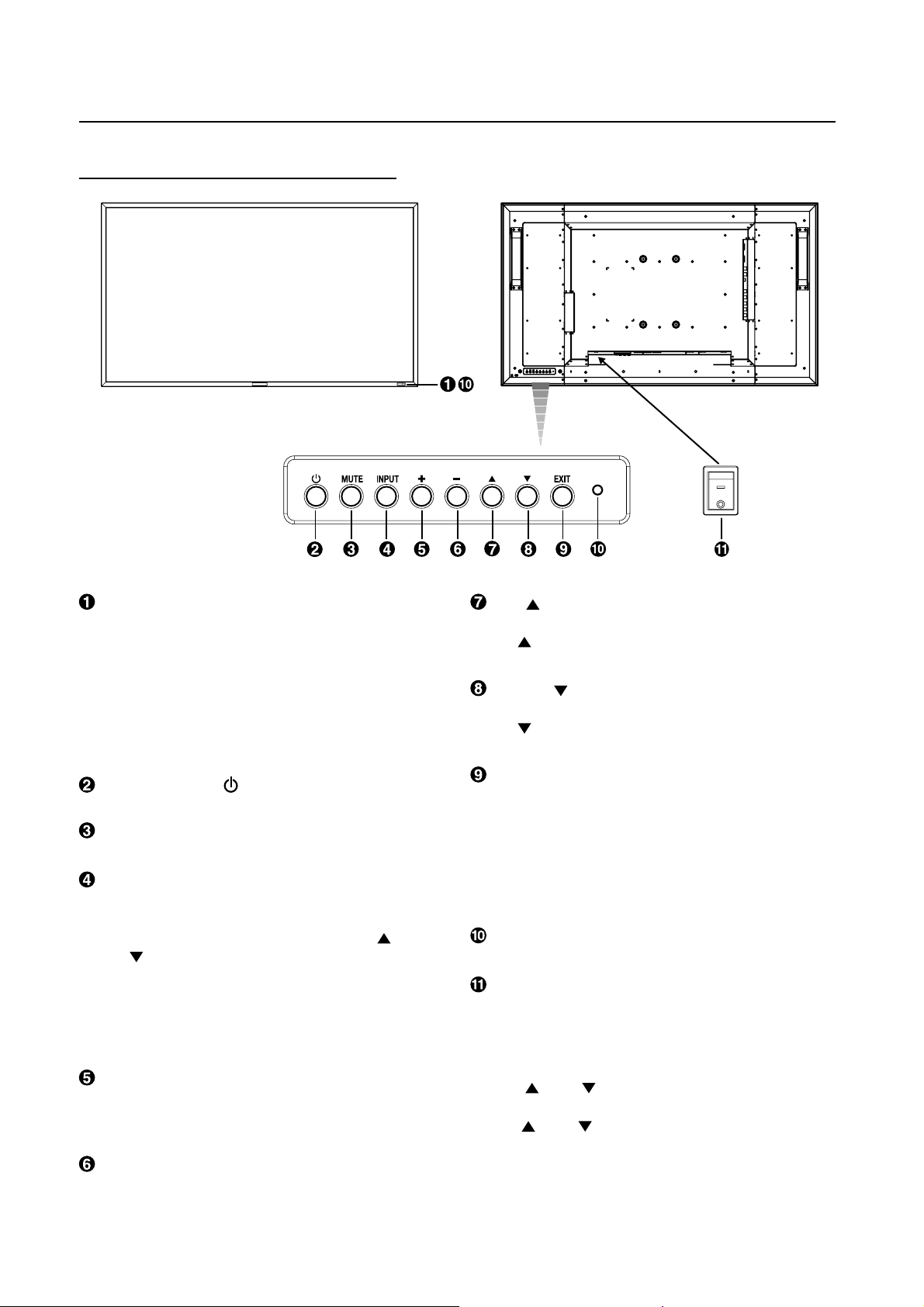
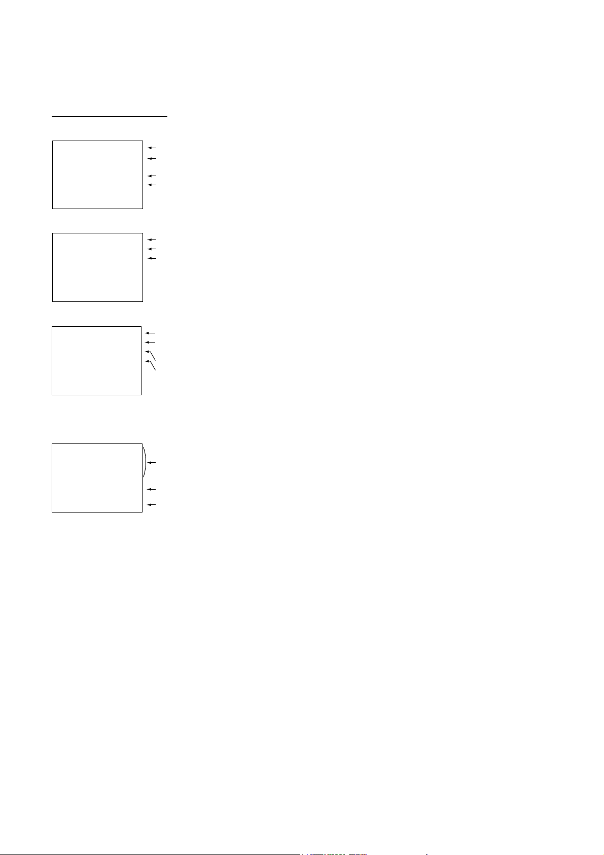
Parts Name and Functions
Buttons, Switch, and Indicator
ON
OFF
Remote control sensor and Power indicator
Receives the signal from the remote control (when using the
wireless remote control). See also page 9.
Glows green when the LCD monitor is in active and glows
red when the LCD is in POWER OFF mode. When the LCD is
in power save mode, it will glow both green and red. When
SCHEDULE is enabled, it will blink green and glow red. See
page 21. In the case of where a failure is detected, it will blink
red.
POWER button ( )
Switches the power on/off. See also page 20.
MUTE button
Switches the audio mute ON/OFF.
INPUT button
Displays the OSD menu for switching the video input.
(Select [RGB1], [RGB2], [RGB3], [RGB4], [RGB5]*, [RGB6],
[DVD/HD], [VIDEO<S>] and [VIDEO] using the UP (
DOWN (
* : [RGB 5] becomes usable when the optional CAT5 Rx BOX
is mounted.
By pressing this button while the OSD menu is being
displayed, you can move forward through the menu items.
(See page 23.)
) buttons.)
) and
PLUS (+) button
Acts as (+) button to increase the adjustment with OSD menu.
Increase the audio output level when the OSD menu is turned
off.
MINUS (-) button
Acts as (-) button to decrease the adjustment with OSD menu.
Decreases the audio output level when the OSD menu is
turned off.
UP ( ) button
Activates the OSD menu when the OSD menu is turned-off.
Acts as
the adjustment with OSD menu.
button to move the highlighted area up to select
DOWN ( ) button
Activates the OSD menu when the OSD menu is turned-off.
Acts as
the adjustment with OSD menu.
button to move the highlighted area down to select
EXIT button
Press the EXIT button to display the OSD menu while it isn’t
being displayed.
By pressing this button while the OSD menu is being
displayed, you can move backward through the menu items.
(You can move forward through the menu items using the
INPUT button.) When you press this button at the Main Menu,
the OSD menu disappears. (See page 23.)
Brightness sensor (front, rear)
Sensor for the auto brightness function. (
See page 25, 33.)
Main Power Switch
On/Off Switch to turn main power on/off.
NOTE: Control Key Lock Mode
This control completely locks out access to all Control Key
functions. To activate the control key lock function, press
both of “
more than 3 seconds. To resume back to user mode, press
both of “
seconds.
” and “ ” and hold down simultaneously for
” and “ ” and hold simultaneously for three (3)
English-6
Page 11
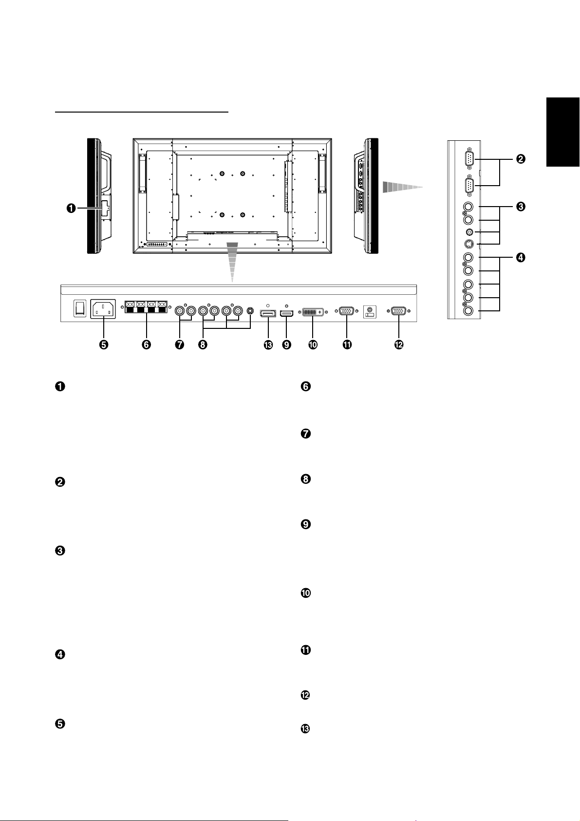
Connectors and Terminals
CAT5 Rx BOX slot
The CAT5 Rx BOX (option) is inserted in this slot. (See page
12.)
NOTE:
Never connect network devices to the CAT5 IN and OUT
connectors. If you do so, they may adversely affect with each
other, causing breakdown.
(OUT)
English
(IN)
(OUT)
(IN)
(IN)
(IN)
EXTERNAL SPEAKER TERMINAL
To output the audio signal for external speakers from AUDIO 1,
2, 3 jack or HDMI.
AUDIO OUT
To output the audio signal from the AUDIO IN 1, 2, 3 jack or
HDMI.
EXTERNAL CONTROL (mini D-Sub 9 pin)
Connect the IN connector with the RS-232C OUT connector
of the computer or a multi-connected MDT421S monitor.
Connect the OUT connector with the RS-232C IN connector
of a multi-connected MDT421S or MDT521S monitor.
VIDEO IN/OUT
VIDEO IN connector (BNC and RCA): To input a composite
video signal. BNC and RCA are not available at the same
time. (Use only one input).
VIDEO OUT connector (BNC): To output the composite
video signal from VIDEO IN connector.
S-VIDEO IN connector (MINI DIN 4 pin): To input the
S-video (Y/C separate signal).
RGB 4 IN / DVD/HD IN (BNC)
To input the analog RGB signals from a computer or other
RGB equipment.
Connecting equipment such as a DVD player, HDTV device,
or Laser disc player. See page 16, 18.
AC IN connector
Connects with the supplied power cord.
AUDIO IN 1, 2, 3
To input the audio signal from external equipment such as a
computer, VCR or DVD player.
RGB 1 IN (HDMI)
To input the digital RGB signals from a computer, DVD player,
etc.
* This connector does not support analog input.
AUDIO is supported via HDMI.
RGB 2 IN (DVI-D)
To input the digital RGB signals from a computer.
* This connector does not support analog input.
AUDIO is supported via DVI-D.
RGB 3 IN (mini D-Sub 15 pin)
To input the analog RGB signals from a computer or other
RGB equipment.
RGB OUT (mini D-Sub 15 pin)
To output the signal from RGB 3, 4 or 5 IN.
RGB 6 IN (DISPLAY PORT)
To input the digital RGB signals from a computer.
English-7
Page 12
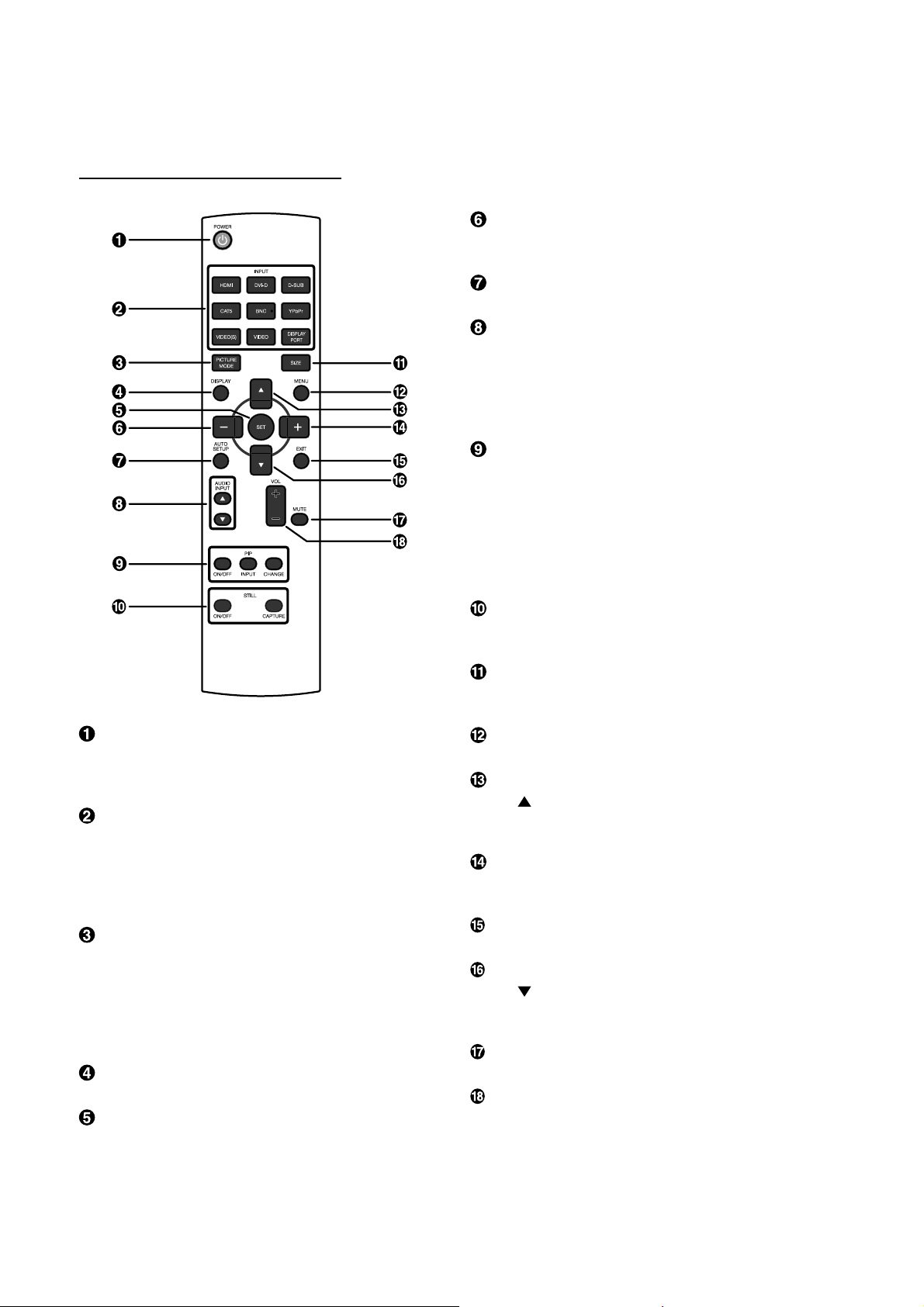
Wireless Remote Control
POWER button
Switches the power on/off.
* If LED Power Indicator on the monitor is not glowing, then
no controls will work.
INPUT button
Selects from input signal, [RGB1] (HDMI), [RGB2] (DVI-D),
[RGB3] (D-SUB), [RGB4] (BNC), [RGB5]* (CAT5), [RGB6] (DISPLAY PORT), [DVD/HD] (YPbPr), [VIDEO<S>] and [VIDEO].
* : [RGB 5] becomes usable when the optional CAT5 Rx BOX
is mounted.
PICTURE MODE button
Selects from picture mode, [HIGHBRIGHT], [STANDARD],
[sRGB], [CINEMA]. See page 21.
HIGHBRIGHT: for moving image such as Video
STANDARD: for images (Factory setting)
sRGB: for text based images
CINEMA: for movies
DISPLAY button
To switch the information OSD on/off. See page 22.
SET button
Acts as SET button with OSD menu.
MINUS button decrease
Acts as (-) button to decrease the adjustment with OSD menu.
Small screen which adjusted “PIP” mode moves left.
AUTO SETUP button
To enter the auto setup menu. See page 28.
AUDIO INPUT button
Press to change the audio source for each video source. The
audio source is changed from [AUDIO1] to [AUDIO2], [AUDIO3]
and [HDMI] in order. Note that you cannot select the audio
source for [VIDEO<S>] or [VIDEO]. [HDMI] is selectable only
when the video source is [RGB 1].
PIP (Picture In Picture) button
ON/OFF button: PIP-ON/OFF. See page 27, 33.
INPUT button: Select the “picture in picture” input signal.
CHANGE button: Replaces to the main picture and sub pic-
ture.
Note:
The “PIP” and “POP” modes do not function when the screen
size is “CUSTOM” or “REAL”.
STILL button
ON/OFF button: To switch the still picture mode on/off.
CAPTURE button: Updates the still picture.
SIZE button
Selects picture size, [FULL], [NORMAL], [CUSTOM] , [DYNAMIC] and [REAL]. See page 21.
MENU button
To switch the menu mode on/off.
UP button
Acts as button to move the highlighted area up to select
the adjustment with OSD menu.
Small screen which adjusted “PIP” mode moves up.
PLUS button increase
Acts as (+) button to increase the adjustment with OSD menu.
Small screen which adjusted “PIP” mode moves right.
EXIT button
Turn to previous menu with OSD menu.
DOWN button
Acts as button to move the highlighted area down to select
the adjustment with OSD menu.
Small screen which adjusted “PIP” mode moves down.
MUTE button
To switch the mute function on/off.
VOLUME button
Increases or decreases the audio output level.
English-8
Page 13
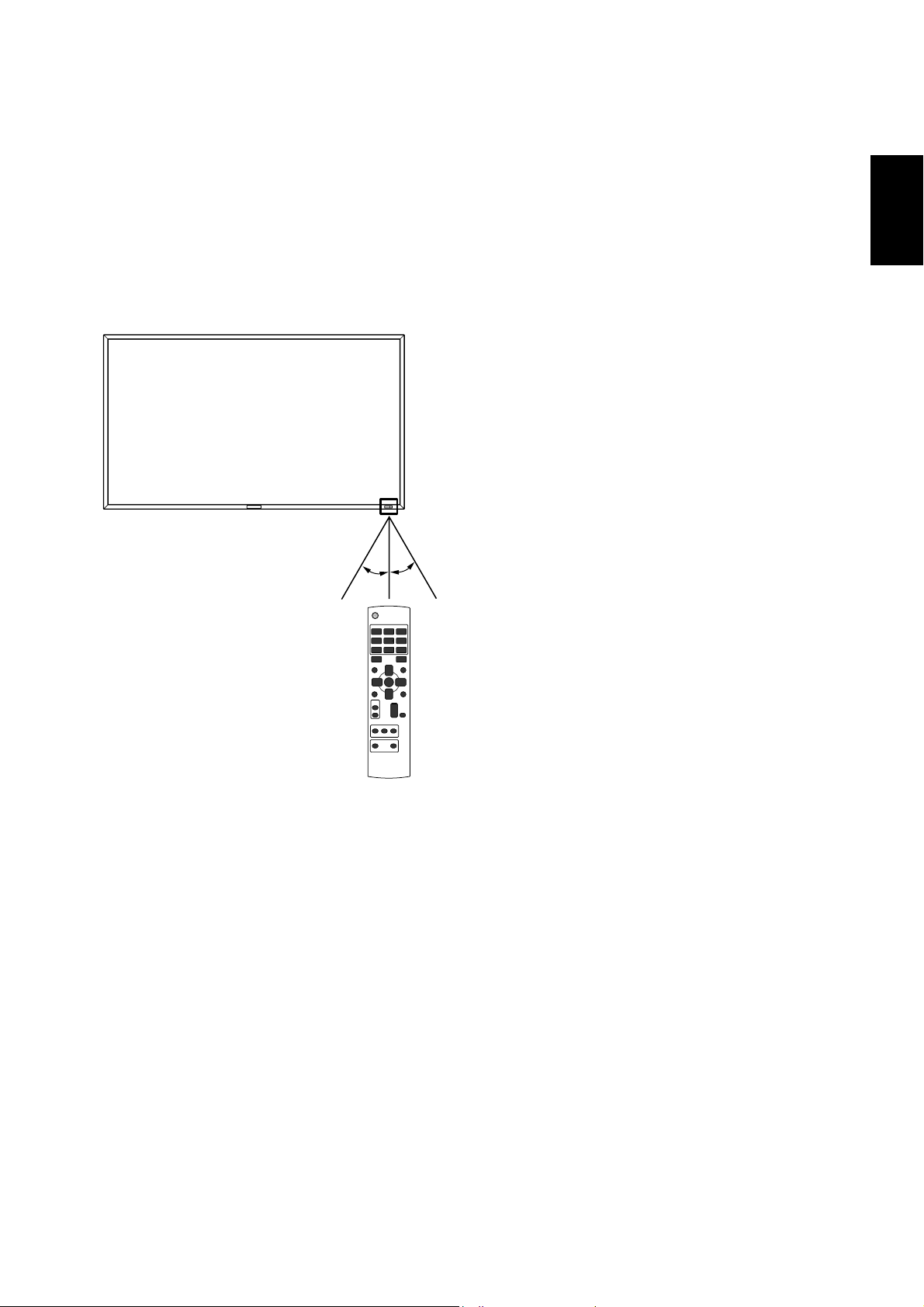
< Operating Range for the Remote
Control >
Point the top of the remote control toward the LCD monitor's
remote sensor during button operation.
Use the remote control within a distance of about 7 m/23 ft.
from the front of the LCD monitor's remote control sensor
and at a horizontal and vertical angle of within 30° within a
distance of about 3 m/10 ft.
30° 30°
English
CAUTION:
Important, the remote control system may not function when
direct sunlight or strong illumination strikes the remote control
sensor of the LCD monitor, or when there is an object in the
path.
< Handling the remote control >
* Do not subject to strong shock.
* Do not allow water or other liquid to splash the remote
control. If the remote control gets wet, wipe it dry immedi-
ately.
* Avoid exposure to heat and steam.
* Other than to install the batteries, do not open the remote.
English-9
Page 14
Setup Procedure
1. Determine the installation location
CAUTION:
DO NOT ATTEMPT TO INSTALL THE LCD MONITOR BY
YOURSELF.
Installing your LCD display must be done by a qualifi ed tech-
nician. Contact your dealer for more information.
CAUTION:
MOVING OR INSTALLING THE LCD MONITOR MUST BE
DONE BY TWO OR MORE PEOPLE.
Failure to follow this caution may result in injury if the LCD
monitor falls.
CAUTION:
Do not mount or operate the display upside down or face
down.
CAUTION:
Do not install the LCD monitor where it will be exposed to
direct sunlight, as this will result in display defects.
CAUTION:
This LCD has a temperature sensor and cooling fan. If the
LCD becomes too hot, the cooling fan will turn on automatically. If the LCD becomes overheated and the cooling fan
is running, the “Caution” menu will appear. If the “Caution”
menu appears, discontinue use and allow the unit to cool.
When the LCD monitor is used in an enclosure or with protection on LCD surface, please check the inside temperature of
monitor by “HEAT STATUS” (See page 31). The temperature is
too hot than normal condition, please set “cooling fan” to ON
on SCREEN SAVER function (See page 28).
IMPORTANT:
Lay the protective sheet, which was wrapped around the LCD
monitor when it was packaged, beneath the LCD monitor so
as not to scratch the panel.
• Place “AAA” batteries matching the + and - signs on each
battery to the + and - signs of the battery compartment.
• Do not mix battery types.
• Do not combine new batteries with used ones. It causes
shorter battery life or leakage of batteries.
• Remove dead batteries immediately to prevent battery
liquid from leaking into the battery compartment. Don't
touch exposed battery acid, it cause damage to your skin.
NOTE:
If you do not intend to use the Remote Control for a long
period, remove the batteries.
3. Connect external equipment
(See pages 15-19)
• To protect the connected equipment, turn off the main
power before making connections.
• Refer to your equipment user manual.
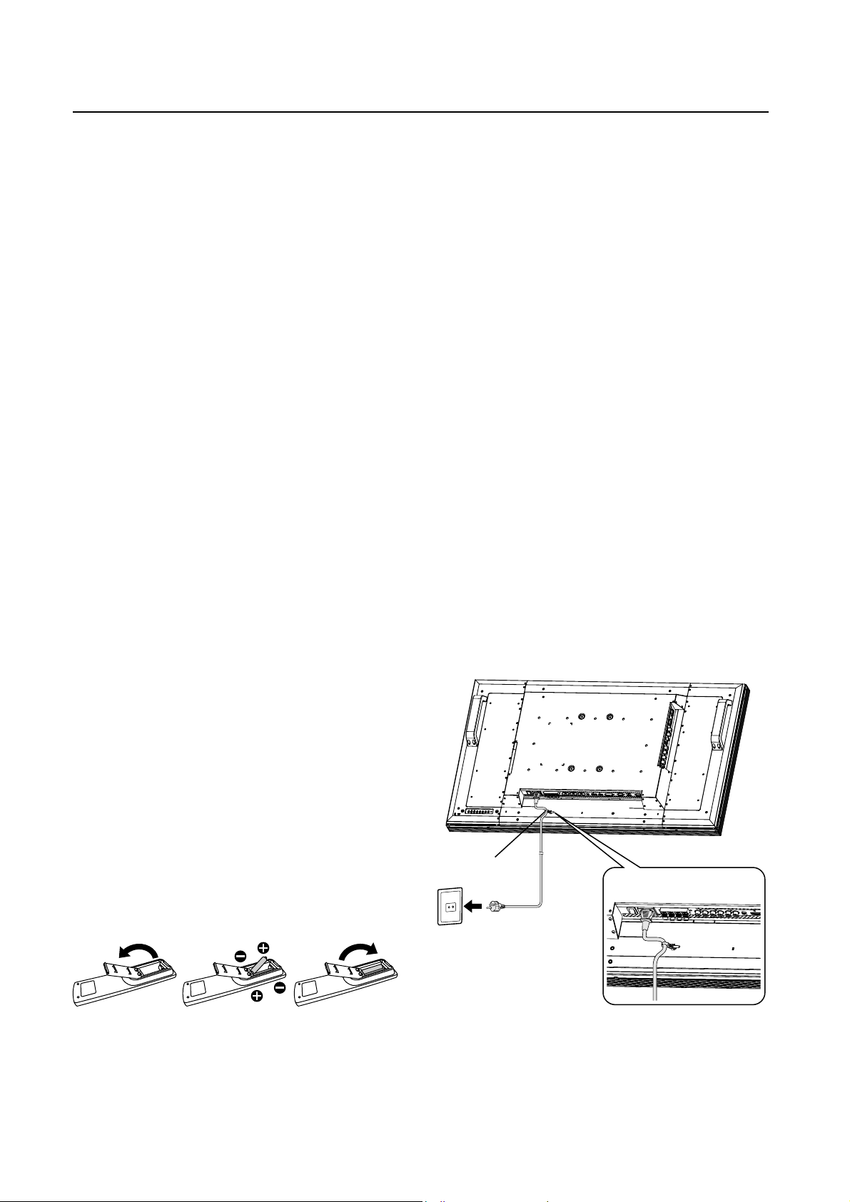
4. Connect the supplied power cord
• The power outlet socket should be installed as near to the
equipment as possible, and should be easily
accessible.
• Fully insert the prongs into the power outlet socket.
Loose connection may cause noise.
NOTE:
Please refer to “Safety Precautions, Maintenance &
Recommended Use” section of this manual for proper
selection of AC power cord.
2. Installing and removing the remote
control batteries
The remote control is powered by 1.5V AAA batteries.
To install or replace batteries:
How to install the batteries
1. Unlock and pull up the cover in the arrow’s direction.
2. Align the batteries according to the (+) and (–) indications
inside the case.
3. Replace the cover.
How to remove the batteries
1. Unlock and pull up the cover in the arrow’s direction.
2. Remove the batteries.
CAUTION:
Incorrect use of batteries can result in leaks or bursting.
Be careful especially about the following points.
English-10
Clamper
Use the clamper
to secure the
cable firmly.
5. Switch on the power of all the
attached external equipment
When connected with a computer, switch on the power of the
computer fi rst.
Page 15
6.
Operate the attached external equipment
Display the signal on the external equipment you wish.
7. Adjust the sound
Make adjustments lowering or rising the volume as required.
8. Adjust the screen (See pages 24-34)
Make adjustments to the display position or settings if required.
9. Adjust the image (See pages 24-34)
Make adjustments to brightness or contrast if required.
10. Recommended Adjustment
To reduce the risk of “image persistence”, please adjust
the following items based on the application being used.
“POWER SAVE” (See page 28), “SCREEN SAVER” (See
page 28), “SIDE BORDER COLOR”(See page 28), “DATE
AND TIME” (See page 31), “SCHEDULE”(See page 31).
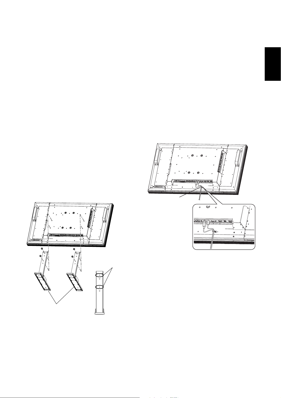
11. Installing and removing the stands
The stands are prepared as option.
Refer to the user’s manual of the stand for more information.
How to install the stands
1. Please turn monitor off.
2. Fasten screws
NOTE:
Install the stands so that their longer portions come to the
front.
How to remove the stands
1. Spread the protective sheet on the fl at surface, such as a
desk.
2. Place monitor on the protective sheet.
3. Remove screws with a screwdriver and place them in a
safe place for reuse.
on both sides of the monitor.
12. Connecting HDMI cable and Display
Port cable
Clamper
English
Stands
(Longer portion
comes to the front.)
Use the clamper
to secure the
cable firmly.
Screw holes for
MDT421S
English-11
Page 16
13. When MDT421S is installed in portrait
position
Conditions
MDT421S can be installed in portrait position, under the following conditions:
Caution:
Portrait position is effective only when wall-mounted or
ceiling-mounted.
The stands (legs) can not be fi tted to the monitor in portrait
position.
Placing the monitor in portrait position, will shorten the average life of the LCD backlight.
Operational Environment (Temperature) shall be limited, as
shown below:
Operational Environment:
Temperature 5 - 35 °C / 41 - 95 °F
Humidity 20 - 80 % (without condensation)
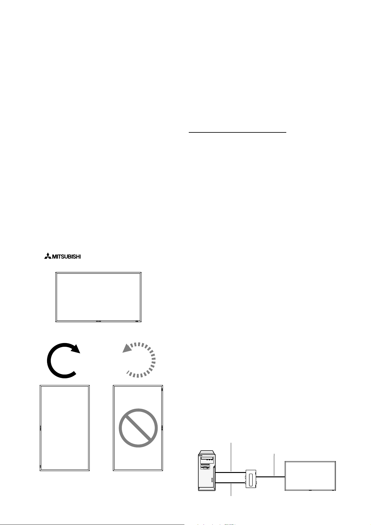
Please orientate the monitor in the direction shown below:
Do not place monitor in landscape in any other manner.
Optional speakers (SP-421S) can not be attached when this
LCD monitor is installed in portrait position.
How to set-up
The “
facing the monitor.
” logo should be on the LEFT side when
Landscape
CounterclockwiseClockwise
90°
90°
14. For long-distance connection using
the CAT5 Kit
NOTE:
The CAT5 Kit is an option designed for MDT421S. For the detailed mounting procedure, see the user’s guide for the CAT5
Kit (option).
CAT5 video connection
The CAT5 video connection function is for transmitting the
analog RGB video signal of the computer and the control
signal of the monitor over a long distance using CAT5 cables.
The computer can control the monitor via the optional CAT5
Tx BOX and the CAT5 Rx BOX that is mounted on MDT421S.
Caution:
Never connect network devices (such as a hub and a computer for LAN) to the CAT5 IN and OUT connectors of the CAT5
Kit. If they are connected, the network devices themselves,
CAT5 Tx BOX, CAT5 Rx BOX, and monitor may be damaged.
1. Installation of the USB driver for CAT5
serial communication control
To connect the computer and the CAT5 Tx BOX via USB interface, it is necessary to install the USB driver to the computer
from the CD-ROM supplied with the CAT5 Kit (option).
(When connecting the computer and the CAT5 Tx BOX via
RS-232C interface, you don’t have to install the USB driver.)
OS supported: Windows
How to install:
1) Installation to Windows
Start the “PL2303-Driver_XP2K_v
Windows XP folder on the CD-ROM supplied with the CAT5
Kit (option) and install the driver according to the instructions
displayed on the screen.
2) Installation to Windows Vista
Start the “PL2303_Prolifi c_Vista_
Windows VISTA folder on the CD-ROM supplied with the
CAT5 Kit (option) and install the driver according to the instructions displayed on the screen.
®
XP, Windows Vista®
®
XP
.exe” fi le in the
******
®
.exe” fi le in the
******
MDT421S
MDT421S
2. Connection of the CAT5 video connec-
tion function
There are two cases of connection.
1) Connection to one monitor
USB cable
Computer
CAT5 cable
CAT5 Tx BOX
(option)
Monitor with CAT5
Rx BOX (option)
VGA (mini D-SUB 15-pin) cable (supplied)
English-12
Page 17
1. Connect the USB connector of the supplied CAT5 Tx BOX
and that of the computer using a commercially available
USB cable. (When the USB driver isn’t available, connect
an RS-232C cable in addition to the USB cable. In this
case, the USB cable serves for supplying the power to the
CAT5 Tx BOX.) See page 35.
2. Connect the D-SUB input connector of the CAT5 Tx BOX
and the VGA (D-SUB) output connector of the computer
using the signal cable (mini D-SUB 15-pin cable) supplied
with the monitor.
3. Connect the modular connector of the CAT5 Tx BOX and
the CAT5 (RGB5) IN connector of the CAT5 Rx BOX using
a commercially available CAT5 cable.
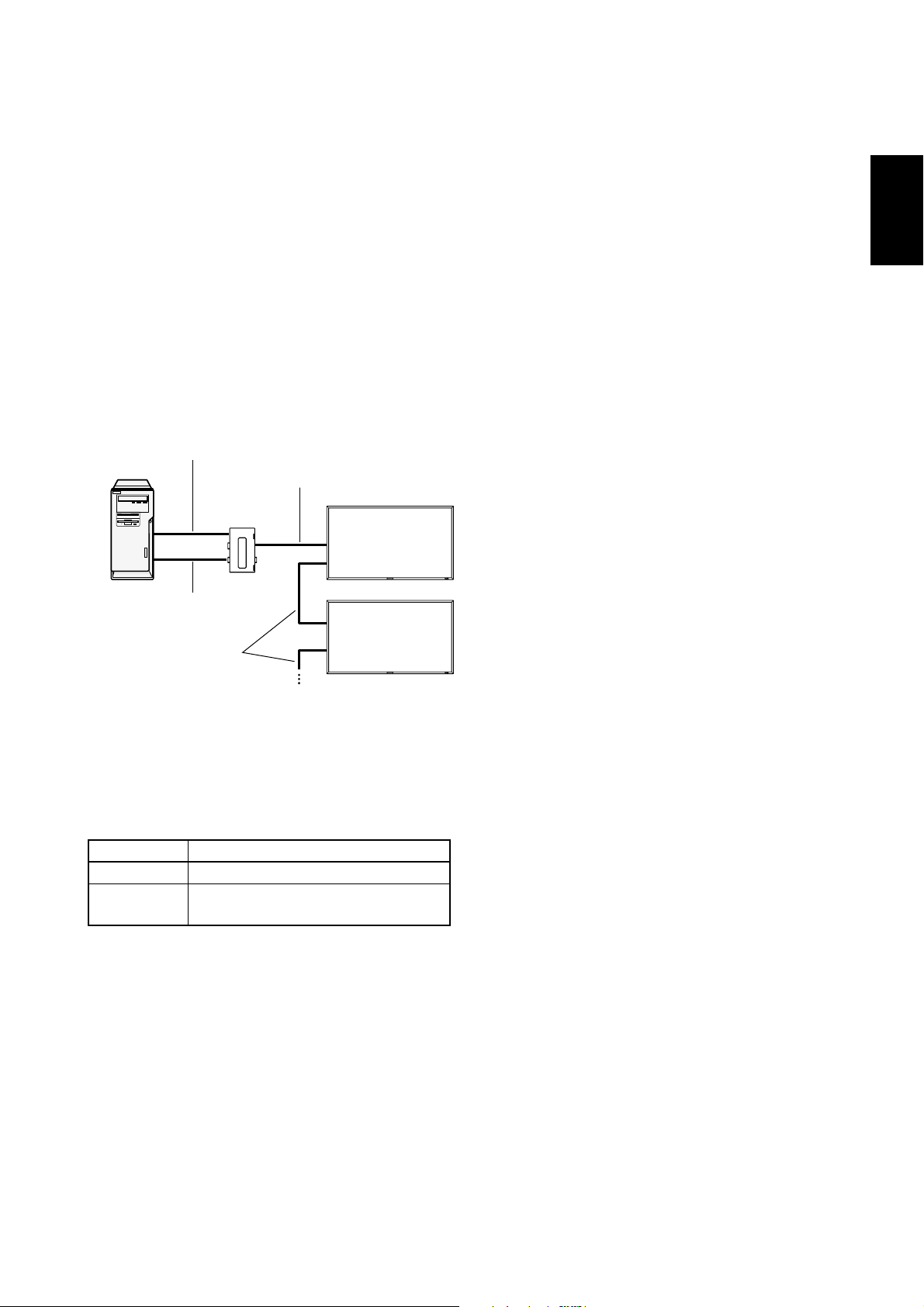
2) Connection to multiple monitors
Computer
VGA (mini D-SUB 15-pin)
cable (supplied)
USB cable
CAT5 Tx BOX
(option)
CAT5 cable
CAT5 cable
Monitor with CAT5
Rx BOX (option)
Monitor supporting
Mitsubishi CAT5
3. Various settings involved in the CAT5
video connection
In the case of the CAT5 video connection, confi gure the fol-
lowing settings displayed on the OSD screen. (See page 29.)
1) CAT5 CABLE LENGTH
Select the cable length, and the defaults of all the adjustment
values are automatically determined.
Select the length that is closest to the actual length of your
cable.
2) CAT5 EQ
Make adjustment so that blur and smear of the displayed letters and graphic objects are minimized.
3) CAT5 R-GAIN/G-GAIN/B-GAIN
When the displayed image is dark, increase each value.
When whites aren’t displayed as intended, adjust the R-GAIN
and B-GAIN values.
4) CAT5 R-SKEW/G-SKEW/B-SKEW
Adjust each value so that the color deviation in the displayed
letters and graphic objects is minimized.
English
1. In addition to the connection made step 1) above, connect the CAT5 OUT connector of the fi rst monitor and the
CAT5 (RGB5) IN connector of the second monitor using a
commercially available CAT5 cable.
2. Connect the third and later monitors in the same way.
You can connect up to 5 monitors.
Allowable cable length
Connection Max. cable length/signal timing
One monitor 150 m / 1920 x 1080 @60 Hz
Multiple moni-
tors
The lengths given above are based on the actual measurements using our standard signal source and the recommended cable as follows. Before installation, check the monitor
operation in advance by connecting it with your computer and
cables.
Recommended cable:
8-pin modular connector, straight-through, shielded, Category
5 or 5e
Commercially available cables that passed the compatibility
test (Tested with shielded connectors commercially available.):
7929A of Belden, NFTP-C5e-GY of Nex1
200 m / 1920 x 1080 @60 Hz
(Total length of the connected cables)
English-13
Page 18
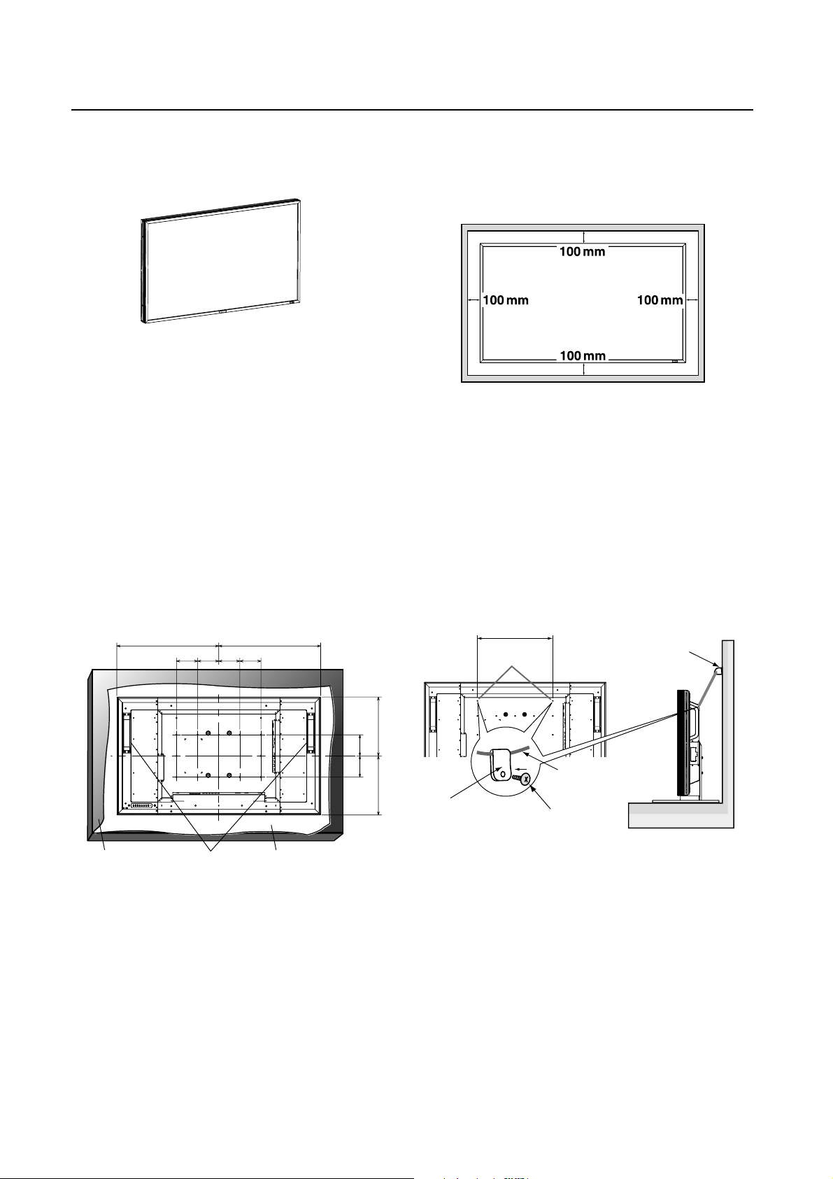
How to Mount and Attach Options to the LCD Monitor
You can attach mounting accessories to the LCD monitor in
one of the following two ways:
1. In the upright position
2. Lay the screen face down
Lay the protective sheet on a table, which was wrapped
around the monitor when it was packaged, beneath the
screen surface so as not to scratch the screen face.
This device cannot be used or installed without the Tabletop
Stand or other mounting accessory. Failure to follow correct
mounting procedures could result in damage to the equipment or injury to the user or installer. Product warranty does
not cover damage caused by improper installation.
Failure to follow these recommendations could result in void-
ing your warranty.
Use M6 screws (having a length 10 mm longer than the thick-
ness of the mounting bracket) and tighten them securely.
Prevent the screws from loosening using spring washers,
etc. MITSUBISHI ELECTRIC recommends using mounting
interface that comply with TÜV-GS and/or UL1678 standard
in North America.
482.8 482.8
100 100 100100
3. Ventilation Requirements for enclosure
mounting
To allow heat to disperse, leave space between surrounding
objects as shown in the diagram below.
4. To avoid monitor from falling
When installing the monitor using the tabletop stands (optional), take measures to prevent the monitor from falling over
in case of an earthquake or other disaster to lessen the probability of injury and damage resulting from fall.
As shown in the fi gure, secure the monitor to a solid wall or
pillar using rope (commercially available) strong enough to
bear the weight of the monitor. (MDT421S: approx. 27 kg (with
the optional stands))
When you use screw hooks (commercially available), ring
screw hooks, not C-shaped screw hooks (with opening), are
recommended.
400 mm
Screw Holes
Screw hook, etc.
commercially available
279.3279.3
100100
(mm)
Table Handles Protective sheet
Caution:
For preventing the monitor from falling.
• Install the monitor with metal brackets for wall or ceiling
installation (commercially available) on your own responsibility. For detailed procedures of installation, refer to the
instructions of the metal brackets.
• To lessen the probability of injury and damage resulting
from fall of the monitor in case of earthquake or other
disaster, be sure to consult the bracket manufacturer for
installation location.
• To lessen the risk of falling of the monitor, thread commercially available rope through the handles at the right and
left of the monitor and secure the rope to the wall mount
brackets or ceiling mount brackets.
• Do not sleep where the monitor may topple over or fall in
case of an earthquake or other disaster.
English-14
Rope, etc.
commercially available
Clamper
Caution:
• The effectiveness of preventing from falling substantially
depends on the strength of brackets and base to which
prevention device from falling is attached. When you
cannot ensure suffi cient strength, provide adequate
reinforcement.
• Though the recommended prevention from falling is
intended to lessen the probability of injury and damage, it
doesn’t assure its effectiveness against any kind of
earthquake or disaster.
• Do not sleep where the monitor may topple over or fall in
case of an earthquake or other disaster.
• Before moving the monitor, remove the rope that is
securing the monitor. Failure to do so may result in injury
or breakdown of the monitor.
Screw
Page 19
Connections
Before making connections:
* First turn off the power of all the attached equipment and make connections.
* Refer to the user manual included with each separate piece of equipment.
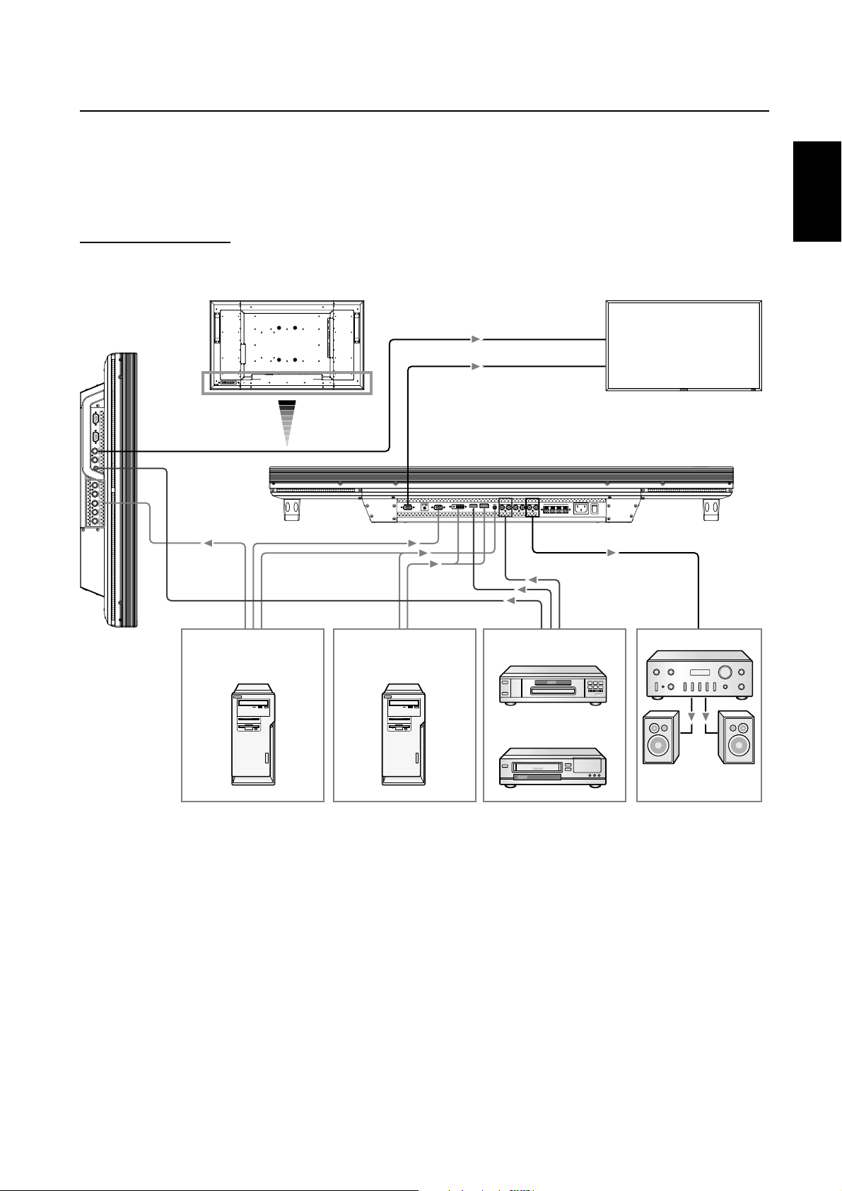
Wiring Diagram
English
LCD monitor
Personal
computer
(analog RGB)
Personal
computer
(DVI-D, DISPLAY PORT)
DVD player
(HDMI)
LCD monitor (second monitor)
Stereo amplifier
VCR
(RCA)
External speaker
English-15
Page 20
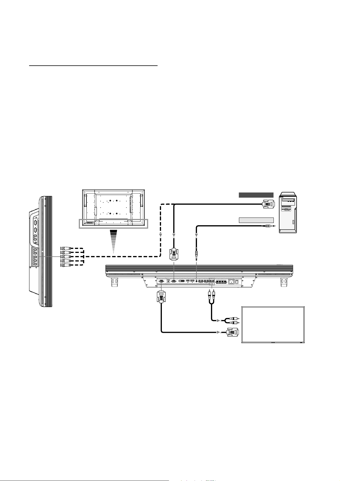
Connecting a Personal Computer
By connecting your computer to your LCD monitor, you can display images on your computer's screen.
Some video cards may not display an image correctly.
Connect the LCD Monitor to a Personal Computer
• To connect the computer to the RGB 3 IN connector (mini D-sub 15 pin) on the LCD monitor, use the supplied RGB signal
cable (mini D-sub 15 pin to mini D-sub 15 pin).
Select “RGB 3” using the INPUT button on the LCD monitor or the D-SUB button on the remote control.
• To connect the computer to the RGB 4 IN connector (BNC) on the LCD monitor, use a signal cable (mini D-sub 15 pin to
BNC x 5).
Select “RGB 4” using the INPUT button on the LCD monitor or the BNC button on the remote control.
• For audio input, select AUDIO IN 1, 2, or 3 using the AUDIO INPUT button.
• To connect a second LCD monitor, use the RGB OUT connector (mini D-sub 15 pin). (The RGB 3, RGB 4, or RGB 5 (option)
signal selected by the fi rst LCD monitor is output.)
• To output audio to the second LCD monitor, use the AUDIO OUT connector.
BNC x 5
LCD monitor
Mini D-sub 15 pin
PC or IBM compatible
To RGB output
Mini D-sub 15 pin
To audio output
Mini D-sub 15 pin
RCA
LCD monitor (second monitor)
RCA
Mini D-sub 15 pin
English-16
Page 21
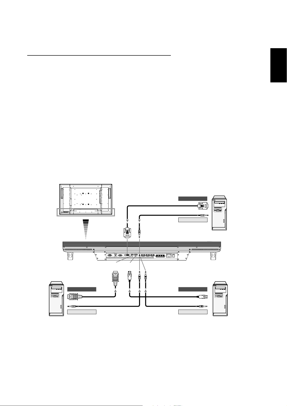
Connecting with Digital Interface Equipment
Connections can be made with equipment that is equipped with a digital interface compliant with the DVI (Digital Visual
Interface) standard.
Connect the LCD Monitor to a Computer with a Digital Output
• To connect the computer to the RGB 2 IN connector (DVI-D) on the LCD monitor, use a DVI-D cable.
Select “RGB 2” using the INPUT button on the LCD monitor or the DVI-D button on the remote control.
Set DVI INPUT MODE to “DVI-PC.” (See page 31.)
• To connect the computer to the RGB 1 IN connector (HDMI) on the LCD monitor, use an HDMI cable.
Select “RGB 1” using the INPUT button on the LCD monitor or the HDMI button on the remote control.
Set HDMI INPUT MODE to “HDMI-PC.” (See page 31.)
• To connect the computer to the RGB 6 IN connector (DISPLAY PORT) on the LCD monitor, use a Display Port cable.
Select “RGB 6” using the INPUT button on the LCD monitor or the DISPLAY PORT button on the remote control.
• For audio input, select AUDIO IN 1, 2, or 3 or HDMI using the AUDIO INPUT button. (HDMI is selectable only when the video
input is “RGB 1.”)
• The signals input from the RGB 1 (HDMI), RGB 2 (DVI-D) and RGB 6 (DISPLAY PORT) connectors aren’t output to the RGB
OUT connector.
LCD monitor
PC or IBM compatible
To RGB output
English
HDMI
DVI-D
HDMI
DVI-D
To audio output
DISPLAY
PORT
PC or IBM compatiblePC or IBM compatible
To RGB outputTo RGB output
DISPLAY PORT
To audio outputTo audio output
English-17
Page 22
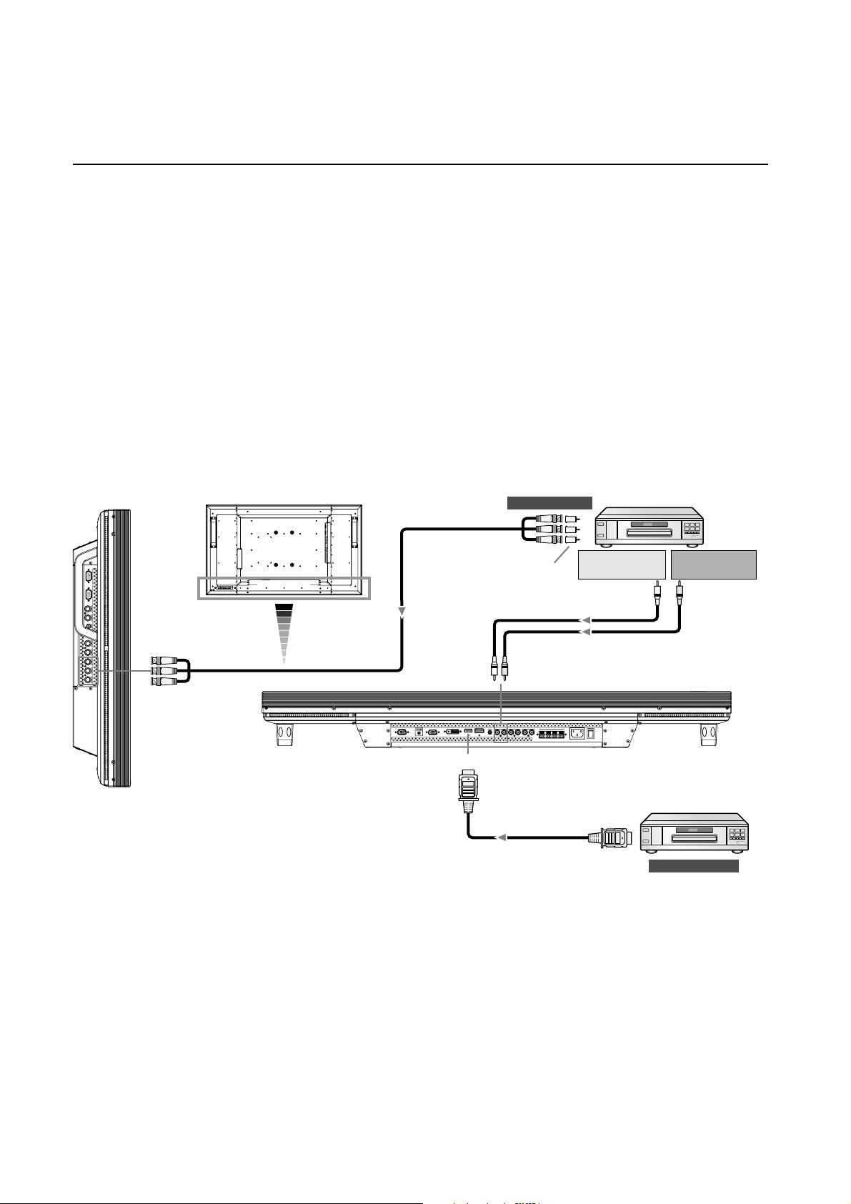
Connecting a DVD Player with component output / HDMI output / DVI output
You can connect DVD players equipped with a component output, HDMI output, and DVI output to your LCD monitor.
Refer to your DVD player owner’s manual for more information.
Connect the LCD Monitor to a DVD Player
• To connect a DVD player equipped with a component output to the DVD/HD IN connector (BNC) on the LCD monitor, you
may need a BNC connector cable (BNC to RCA adaptor).
Select “DVD/HD” using the INPUT button on the LCD monitor or the YPbPr button on the remote control.
• To connect a DVD player equipped with an HDMI output to the RGB 1 IN connector (HDMI) on the LCD monitor, use an
HDMI cable.
Select “RGB 1” using the INPUT button on the LCD monitor or the HDMI button on the remote control.
Set HDMI INPUT MODE to “HDMI-HD.” (See page 31.)
• For audio input, select AUDIO IN 1, 2, 3 or HDMI using the AUDIO INPUT button. (HDMI is selectable only when the video
input is “RGB 1.”)
BNC x 3
LCD monitor
BNC x 3
HDMI
To video output
BNC-RCA
adapter
RCA
DVD Player
To audio outputLTo audio output
R
RCA
DVD Player
HDMI
To HDMI output
NOTE:
Operations of the connected HDMI device aren’t always guaranteed.
English-18
Page 23
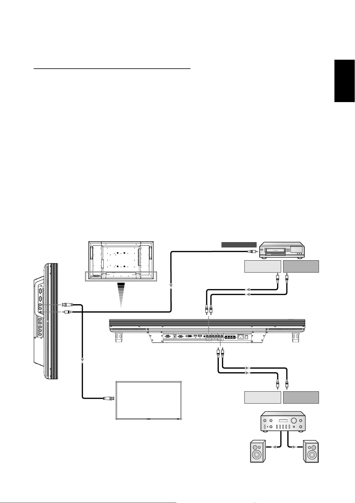
Connecting to a VCR / Stereo Amplifi er
You can connect your VCR / stereo amplifi er to your LCD monitor. Refer to your VCR / stereo amplifi er owner's manual for more
information.
Connect the LCD Monitor to a VCR / Stereo Amplifi er
• To connect the VCR to the VIDEO IN connector (RCA, BNC, or S-VIDEO) on the LCD monitor, use a video cable or S-video
cable.
For connection to the AUDIO IN connector on the LCD monitor, use an RCA cable (audio cable).
Connect the connectors of the RCA cable (audio cable) properly.
When connecting the VCR to the RCA or BNC connector, select “VIDEO” using the INPUT button on the LCD monitor or the
VIDEO button on the remote control.
When connecting the VCR to the S-VIDEO connector, select “VIDEO<S>” using the INPUT button on the LCD monitor or the
VIDEO button on the remote control.
• Before connecting a stereo amplifi er to the LCD monitor, be sure to turn off the stereo amplifi er.
For connection to the AUDIO OUT connector on the LCD monitor, use an RCA cable (audio cable).
Connect the connectors of the RCA cable (audio cable) properly.
Turn on the LCD monitor fi rst, and then turn on the stereo amplifi er.
• The audio input signal selected by the LCD monitor is output from the AUDIO OUT connector.
NOTE:
For video signal input, use either of the RCA or BNC connector.
English
BNC
RCA
LCD monitor
LCD monitor (second monitor)
BNC
VCR
To video output
RCA
To audio outputLTo audio output
R
RCA
RCA
RCA
RCA
To audio inputLTo audio input
R
Stereo amplifier
English-19
External
speaker
Page 24
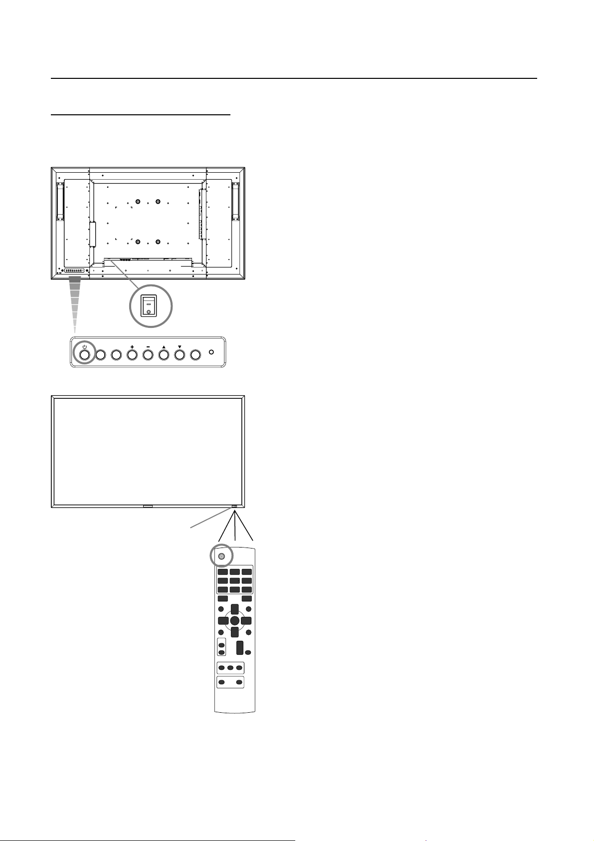
Basic Operation
Power ON and OFF Modes
The LCD monitor power indicator will turn green while powered on or red in off mode. The monitor can be powered on or off
using the following three options:
1. Pressing the Main Power Switch.
NOTE:
When the Main Power Switch is used to power off the
LCD monitor, the remote control and the power button will
not activate the on mode and both green and red power
indicator turn off. Be sure to turn the Main Power Switch
to the on mode before using these two options.
ON
OFF
2. Pressing the power button.
EXITMUTE INPUT
NOTE:
Before pressing the power button, be sure to turn on the
Main Power button on the LCD monitor.
Power indicator
3. Using the remote control.
NOTE:
Before operating the remote control, be sure to turn on
the Main Power Switch on the LCD monitor.
English-20
Page 25
Power Indicator
O
Status
Power ON Green
Power OFF Red
Power Standby when
“SCHEDULE” is enable
Power Standby Red, Green
Diagnosis
(Detecting failure)
Red On
Green Blinking
Red Blinking
See troubleshooting on
*
page 38.
Using Power Management
The LCD monitor follows the VESA approved DPM Power
Management function.
The power management function is an energy saving
function that automatically reduces the power consumption
of the display when the keyboard or the mouse has not been
used for a fi xed period.
The power management feature on your new display has
been set to the “ON” mode. This allows your display to enter
a Power Saving Mode when no signal is applied. This could
potentially increase the life and decrease the power
consumption of the display.
Selecting a video source
To view a video source:
Use the input button to set [VIDEO].
Use the COLOR SYSTEM menu to set [AUTO], [NTSC],
[PAL], [SECAM], [PAL60], [4.43NTSC], according to your
video format.
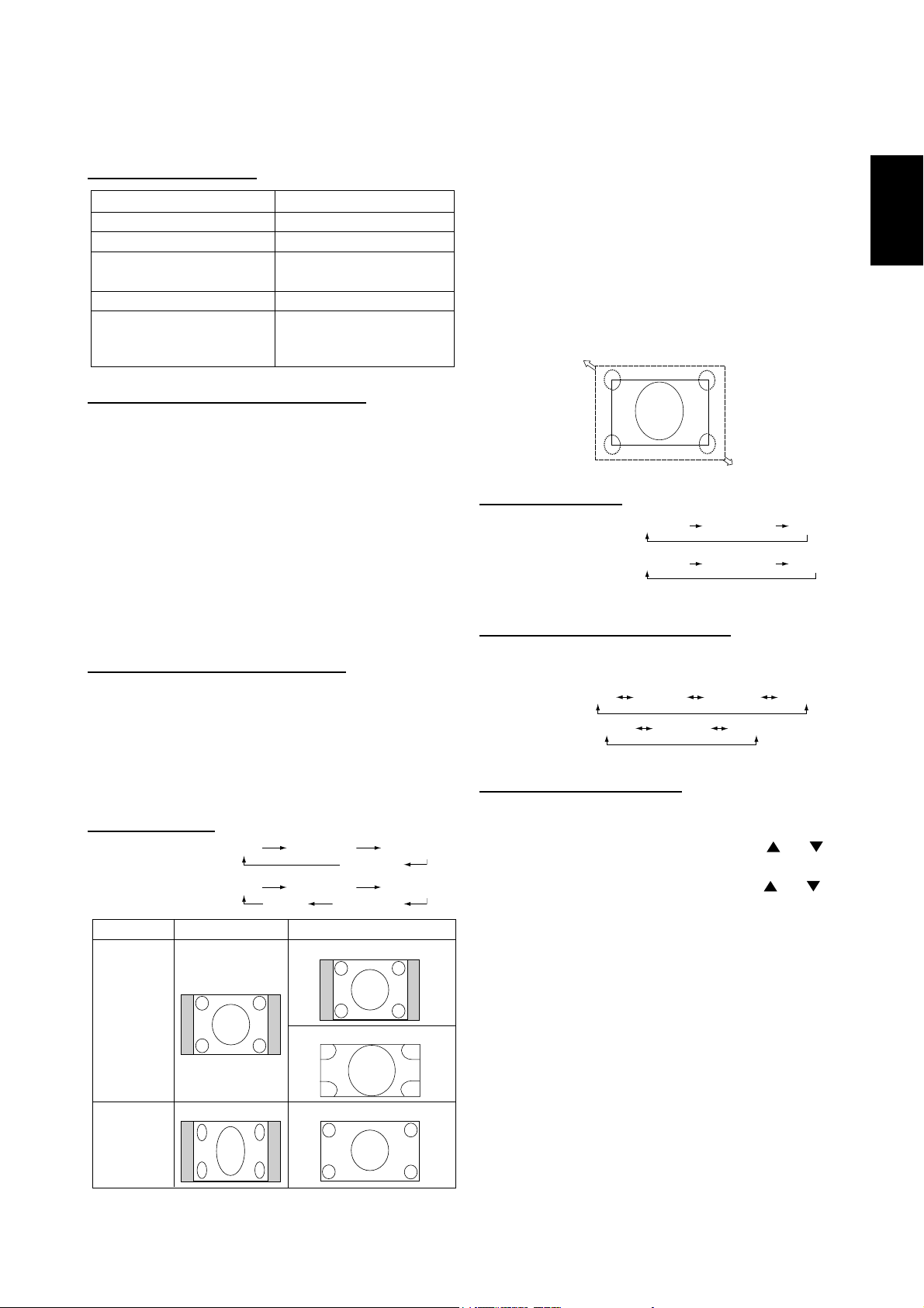
Picture Size
RGB 1, 2, 3, 4, 5, 6
DVD/HD, VIDEO<S>,
VIDEO
Signal Type
FULL NORMAL CUSTOM
REAL
FULL NORMAL DYNAMIC
CUSTOMREAL
NORMAL SIZE Recommended Size
NORMAL
NORMAL: Display the input signal aspect ratio from the PC
signal, or display in 4:3 aspect ratio from the DVD/HD or
VIDEO signal.
FULL: Display in entire screen.
DYNAMIC: Expand 4:3 pictures to the entire screen with
non-linearity. (Some round image will be cut by expansion.)
CUSTOM (ZOOM): Image can be expanded beyond the
active display area. The image which is outside of active display area is not displayed.
REAL: Image will be displayed 1 by 1 pixel.
ZOOM
ZOOM
Picture Mode
RGB 1, 2, 3, 4, 5, 6
DVD/HD, VIDEO<S>,
VIDE
HIGHBRIGHT
HIGHBRIGHT
STANDARD
STANDARD
sRGB
CINEMA
Audio Source Switching
You can switch the audio source using the AUDIO INPUT
button.
RGB 1, 2, 6
Other than
RGB 1, 2, 6
HDMI
AUDIO1
AUDIO1 AUDIO2 AUDIO3
AUDIO2 AUDIO3
Control Lock Mode
This function disables the operation buttons so that the adjustments you make are not changed when they are pressed.
To disable the buttons, press and hold down the
buttons together for at least 3 seconds.
To enable the buttons, press and hold down the
buttons together for at least 3 seconds again.
and
and
English
4:3
Squeeze
DYNAMIC
FULL
English-21
Page 26
Information OSD
RGB1, 2, 3, 4, 5, 6
RGB3
1024 x 768
48kHz 60Hz
AUDIO : 1
SIZE : FULL
DVD/HD
DVD/HD
AUDIO : 3
SIZE : FULL
VIDEO<S>, VIDEO
VIDEO<S>
NTSC
AUDIO : 3
SIZE : NORMAL
)
Video Input mode
Input signal Information
Audio input mode
Picture Size mode
Video Input mode
Audio input mode
Picture Size mode
Video Input mode
Input Signal Color System mode
Audio input mode
Picture Size mode
PIP or POP
Main:RGB3
Sub:VIDEO<S>
RGB3
1024 x 768
48kHz 60Hz
AUDIO : 1
VIDEO<S>
NTSC
SIZE : FULL
Main picture Information
Sub picture Information
)
Main picture Information
English-22
Page 27
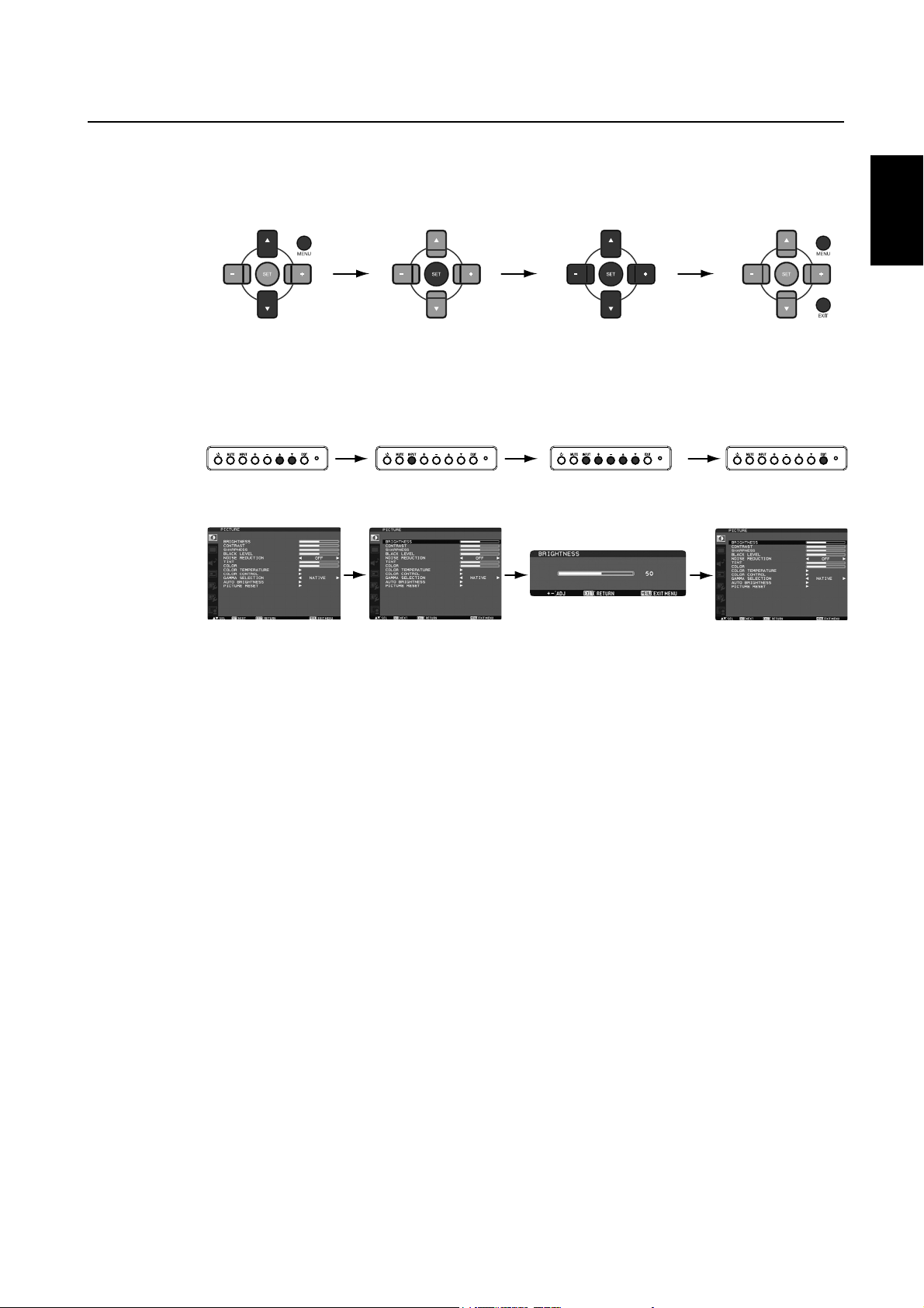
OSD (On-Screen-Display) Controls
Remote Control
Control Panel
OSD screen
Press MENU button to
open Main menu. Press
UP or DOWN button to
select sub-menu.
Press EXIT button to
open Main menu.
Press UP or DOWN
button to select
sub-menu.
Press SET button
to decide.
Press INPUT button
to enter the selected
sub-menu.
Press UP or DOWN, and PLUS
or MINUS button to select
function, or control which you
like.
Press SET button to decide.
After selecting the sub-menu
using UP or DOWN button
and pressing INPUT button to
enter the selected sub-menu,
make adjustment using PLUS
or MINUS button.
Press MENU or EXIT
button to exit.
English
Press EXIT button to go
back to the previous
menu screen. By pressing
EXIT button at MainMenu, Main-Menu
disappears.
English-23
Page 28
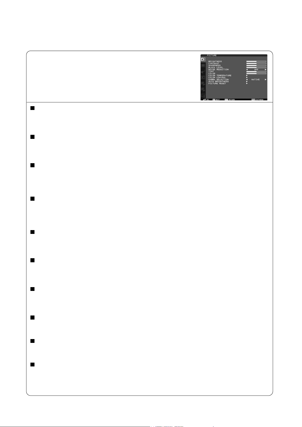
Main-Menu
PICTURE
BRIGHTNESS
Adjusts the overall image and background screen brightness.
Press + button to increase brightness.
Press - button to decrease brightness.
CONTRAST
Adjusts the image brightness in relation to the input signal.
Press + button to increase contrast.
Press - button to decrease contrast.
SHARPNESS
This function is digitally capable to keep crisp image at any timings.
It is adjustable to get a distinct image or a soft one as you prefer and set independently for each picture mode.
Press + button to increase sharpness.
Press - button to decrease sharpness.
BLACK LEVEL
Adjusts the image brightness in relation to the background.
Press + button to increase black level.
Press - button to decrease black level.
NOTE: sRGB picture mode is standard and cannot be changed.
NOISE REDUCTION * :
Adjusts the noise reduction level.
Press + button to increase reduction level.
Press - button to decrease reduction level.
INPUT RGB1 (HDMI INPUT MODE: HDMI-HD), RGB2 (DVI INPUT MODE: DVI-HD), DVD/HD, VIDEO<S>, VIDEO only
TINT * : INPUT RGB1 (HDMI INPUT MODE: HDMI-HD), RGB2 (DVI INPUT MODE: DVI-HD), DVD/HD, VIDEO<S>, VIDEO only
Adjust the tint of all color, or red, magenta, blue, cyan, green, and yellow individually.
Press + button the flesh tone color becomes greenish.
Press - button the flesh tone color becomes purplish.
COLOR * : INPUT RGB1 (HDMI INPUT MODE: HDMI-HD), RGB2 (DVI INPUT MODE: DVI-HD), DVD/HD, VIDEO<S>, VIDEO only
Adjust the color saturation of all color, or of red, magenta, blue, cyan, green, and yellow individually.
Press + button to increase color depth.
Press - button to decrease color depth.
COLOR TEMPERATURE
Use to adjust the color temperature.
The image becomes reddish as the color temperature decreases, and it becomes bluish as the color temperature increases.
COLOR CONTROL
The color levels of red, green, and blue are adjusted by the color bars.
R: Red, G: Green, B: Blue
GAMMA SELECTION
Selects a display gamma.
2.2, 2.4, OPTION, S gamma, Native
NOTE: sRGB picture mode is standard and cannot be changed.
English-24
Continued on next page.
Page 29
Continued from previous page.
AUTO BRIGHTNESS
This function controls the screen brightness depending on the ambient light for easy viewing.
In addition, it changes the screen brightness depending on the ambient light and what are displayed on the screen to
reduce power consumption as low as possible.
[AUTO BRIGHTNESS]
LOCAL: The auto brightness function is enabled.
REMOTE: The auto brightness function is enabled. In addition, the monitor enters the intercommunication mode where
multiple monitors are controlled collectively. (See page 33.)
OFF: This function is disabled.
[CONTROL]
PRIMARY: Select this setting to configure the monitor as Master when controlling multiple monitors collectively.
SECONDARY: Select this setting to use the monitor alone or to configure the monitor as Slave when controlling multiple
monitors collectively.
[LIGHT FROM BACK]
YES: Select this setting when there is a light source such lighting equipment and a window behind the monitor.
NO: Select this setting when there is no light source such lighting equipment and a window behind the monitor.
[BACK WALL]
Select the following settings according to the distance between the rear of the monitor and the wall or window.
FAR: The distance is 5 meters or longer.
NEAR: The distance is 5 meters or shorter.
[FRONT SENSOR]
Select ON for normal use.
OFF: Select this setting when the sensor on the front panel is shielded.
English
[REAR SENSOR]
Select ON for normal use.
OFF: Select this setting when the sensor on the rear panel is shielded.
[SATURATION]
ON: The image saturation is adjusted depending on the ambient light.
OFF: Image saturation isn't adjusted.
[VIDEO DETECT]
ON: The screen brightness varies depending on what are displayed on the screen to reduce power consumption of the
monitor.
OFF: The screen brightness doesn’t vary and the power consumption isn’t reduced.
PICTURE RESET
Selecting Picture reset allows you to reset all OSD settings about PICTURE setting.
Select “Yes” and press “SET” button to restore to factory preset data.
Press “EXIT” button to cancel and then return to the previous menu.
English-25
Page 30
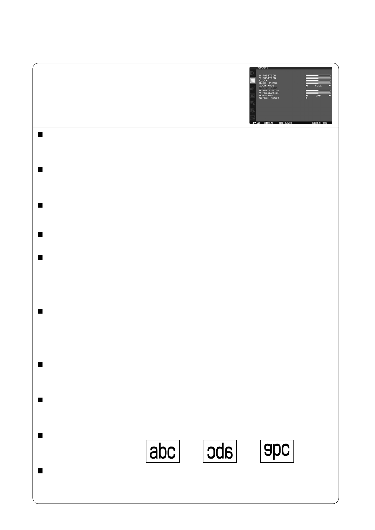
Main-Menu
SCREEN
H POSITION
Controls Horizontal Image position within the display area of the LCD.
Press + button to move screen to right.
Press - button to move screen to left.
V POSITION
Controls Vertical Image position within the display area of the LCD.
Press + button to move screen to UP.
Press - button to move screen to DOWN.
CLOCK * : INPUT RGB3, 4, 5 only
Press + button to expand the width of the image on the screen the right.
Press - button to narrow the width of the image on the screen the left.
CLOCK PHASE * : INPUT RGB3, 4, 5 only
Improves focus, clarity and image stability by increasing or decreasing this setting.
ZOOM MODE
You can select “FULL”, “NORMAL” and “CUSTOM” and “REAL”. (INPUT RGB1, 2, 3, 4, 5, 6 only) You can also select “FULL”,
“NORMAL” “DYNAMIC” and “CUSTOM” and “REAL”. (INPUT DVD/HD, VIDEO<S>, VIDEO only)
Selecting “DYNAMIC” will make the screen display panoramic with the expansion of the middle and outside of the screen
changed. (The upper and the bottom of the image will be cut by expansion.)
Dynamic image is the same as FULL size image when HDTV signal is input.
Selecting “REAL” image will be displayed 1 by 1 pixel.
CUSTOM ZOOM
“CUSTOM ZOOM” will be selected when you select “CUSTOM” on the screen “ZOOM” mode.
ZOOM: expands the horizontal and the vertical size simultaneously.
HZOOM: expands the horizontal size only.
VZOOM: expands the vertical size only.
H POSITION: moves to the right with + button. moves to the left with – button.
V POSITION: moves up with + button. moves down with – button.
H RESOLUTION * : INPUT RGB1, 2, 3, 4, 5, 6 only
Adjusts the horizontal size by increasing or decreasing the setting.
Press + button to expand the width of the image on the screen.
Press - button to narrow the width of the image on the screen.
V RESOLUTION * : INPUT RGB1, 2, 3, 4, 5, 6 only
Adjusts the vertical size by increasing or decreasing the setting.
Press + button to expand the height of the image on the screen.
Press - button to narrow the height of the image on the screen.
ROTATION
The OSD screen is rotated.
OFF H FLIP V FLIP
SCREEN RESET
Selecting Screen reset allows you to reset all OSD settings from PICTURE setting.
Select “Yes” and press “SET” button to restore the factory preset data.
Press “EXIT” button to cancel and then return to the previous menu.
Horizontally rotated Vertically rotated
English-26
Page 31

Main-Menu
AUDIO
BALANCE
Adjust the balance of L/R volume.
Press + button to move the stereo sound image to right.
Sound of the left side will be small.
Press - button to move the stereo sound image to left.
TREBLE
To accentuate or reduce the high frequency sound.
Press + button to increase TREBLE sound.
Press - button to decrease TREBLE sound.
BASS
To accentuate or reduce the low frequency sound.
Press + button to increase BASS sound.
Press - button to decrease BASS sound.
AUDIO RESET
Selecting Audio reset allows you to reset all OSD settings from AUDIO setting.
Select “YES” and press “SET” button to restore the factory preset.
Press “EXIT” button to cancel and then return to the previous menu.
English
Main-Menu
PIP (PICTURE IN PICTURE)
Note: The “PIP” and “POP” modes do not function when the screen size is “CUSTOM” or “REAL”.
PIP SIZE
Selecting the size of picture inserted at the “Picture-in-Picture” (PIP) mode.
“Large”, “Middle” and “Small” are available.
PIP AUDIO
Selecting the sound source in PIP mode.
When selecting “MAIN AUDIO”, you will get the sound for the main picture and when selecting “PIP AUDIO”,
you will get the sound for the picture instead.
PIP RESET
Selecting PIP Reset allows you to reset all OSD settings from PIP setting.
Select “Yes” and press “SET” button to restore the factory preset data.
Press “EXIT” button to cancel and then return to the previous menu.
English-27
Page 32

Main-Menu
CONFIGURATION 1
AUTO SETUP * : INPUT RGB3, 4, 5 only
Press “SET” button to automatically adjust screen size, horizontal position, vertical position, clock, clock phase,
white level and black level.
Press “EXIT” button to cancel execution AUTO SETUP and then will return to the previous menu.
AUTO ADJUST * : INPUT RGB3, 4, 5 only
Selecting the auto adjust ON/OFF.
Selecting ON when changing the timing, the horizontal position, vertical position and clock-phase will adjust automatically.
POWER SAVE
Selecting RGB “ON”, the monitor will go to power management mode when RGB1, 2, 3, 4, 5, 6 sync is lost.
Selecting VIDEO “ON”, the monitor will go to power management mode after about 10 minutes delay from when DVD/HD,
VIDEO<S> and VIDEO input signal is lost.
LANGUAGE
OSD control menus are available in eight languages.
(English, German, Spanish, French, Italian, Swedish, Chinese and Japanese)
SCREEN SAVER
Select “SCREEN SAVER” functions to reduce the risk of the “image persistence”.
GAMMA: The display gamma is changed and fixed when selected “ON”.
COOLING FAN: The built in cooling fan is always on when set “ON”. When “AUTO” is selected, the built-in cooling fan starts
rotating automatically when the internal temperature exceeds the operation guarantee range.
BRIGHTNESS: The brightness is decreased when selected “ON”.
MOTION: Image is slightly expanded and moves 4 directions (UP, DOWN, RIGHT, LEFT) periodically
(Need setting the time for movement).
Movement area is approximately +/- 10mm from original position;
Please locate the important information such as text within 90% area of screen image.
See “IMAGE PERSISTENCE” on page 32 for this function.
PIP and STILL will be disabled when “MOTION” is active.
COLOR SYSTEM * : INPUT VIDEO<S>, VIDEO only
Selecting the Color System depends on your input video format.
AUTO: NTSC, PAL, SECAM, PAL60 or 4.43 NTSC is automatically selected.
NTSC: Specific selection of NTSC.
PAL: Specific selection of PAL.
SECAM: Specific selection of SECAM.
PAL-60: Specific selection of PAL60.
4.43NTSC: Specific selection of 4.43 NTSC.
SIDE BORDER COLOR
Use to adjust the brightness of the black areas displayed on both sides of 4:3 image.
OFF, 50, and 100 are selectable.
CONFIGURATION RESET
Selecting the CONFIGURATION RESET allows you to reset all configuration settings.
Select “Yes” and press “SET” button to restore the factory preset data.
Press “EXIT” button to cancel and return the previous menu.
FACTORY RESET
Selecting “YES” allows you to reset PICTURE, SCREEN, AUDIO, CONFIGURATION1,2 and ADVANCED OPTION will be back
to factory settings (except LANGUAGE, DATE AND TIME, HDMI INPUT MODE, DVI INPUT MODE, DDC/CI, MONITOR ID and
SCHEDULE).
Select “YES” and press “SET” button to restore the factory preset data. Press “EXIT” button to cancel and return the
previous menu.
English-28
Page 33

Main-Menu
CONFIGURATION 2
CAT5 CONTROL * : Selectable only when the optional CAT5 Rx BOX is mounted.
[CAT5 CABLE LENGTH]
Select the cable length, and the defaults of all the adjustment values are automatically determined.
Select the length that is closest to the actual length of your cable.
[CAT5 EQ]
Make adjustment so that blur and smear of the displayed letters and graphic objects are minimized.
[CAT5 R-GAIN, G-GAIN, B-GAIN]
When the displayed image is dark, increase each value.
When whites aren't displayed as intended, adjust the R-GAIN and B-GAIN values.
[CAT5 R-SKEW, G-SKEW, B-SKEW]
Adjust each value so that the color deviation in the displayed letters and graphic objects is minimized.
SERIAL CONTROL * : Selectable only when the optional CAT5 Rx BOX is mounted.
Select the communication interface (RS232 or RS485) for the serial communication function.
For connection of the signal cable, see page 35.
English
RS485 TERMINATION * : Selectable only when the optional CAT5 Rx BOX is mounted.
Turn ON or OFF the termination resistance of the RS-485 interface.
ON: Select this setting to use the monitor alone or to configure the monitor as the one at the end of the connection when more
than one monitor is multi-connected.
OFF: Select this setting to configure the monitor as other than the one at the end of the connection when more than one
monitor is multi-connected.
OSD TURN OFF
The OSD control menu will stay on as long as it is use. In the OSD Turn Off submenu, you can select how long the monitor
waits after the last touch of a button to shut off the OSD control menu.
The preset choices are 5 -120 seconds.
INFORMATION OSD
Selects the information OSD display or not.
The information OSD will display when input signal or source change or warning message like as no-signal or out-of range.
A time between 1 to 10 seconds is available.
OFF TIMER
To select OFF TIMER mode ON/OFF.
In the OFF TIMER menu, you can preset the monitor to automatically power down.
A time between 1 to 24 hours is available.
When the OFF TIMER is set, the SCHEDULE (see page 31) settings will be disabled.
OSD H POSITION
Adjusts the horizontal position of the OSD menu.
OSD V POSITION
Adjusts the vertical position of the OSD menu.
MONITOR INFORMATION
Indicates the model and serial number of your monitor.
English-29
Page 34

Main-Menu
ADVANCED OPTION
INPUT RESOLUTION * : INPUT RGB3, 4, 5 only
Selects to decision of input signal about below timings, 1024x768, 1280x768 and 1360x768.
AUTO: Determines the resolution automatically.
1024x768: Determines the resolution as 1024x768
1280x768: Determines the resolution as 1280x768
1360x768: Determines the resolution as 1360x768
The setting you select becomes effective when POWER is turned OFF and ON again.
BLACK LEVEL EXPANSION
Selects a level of black expansion from “OFF”, “MIDDLE” and “HIGH.”
In case of go under the black cut-off level, please adjust the “Black level” in moderation on OSD menu.
* : INPUT RGB1 (HDMI INPUT MODE: HDMI-HD), RGB2 (DVI INPUT MODE: DVI-HD), DVD/HD, VIDEO<S>, VIDEO only
SCAN MODE * : INPUT RGB1 (HDMI INPUT MODE: HDMI-HD), RGB2 (DVI INPUT MODE: DVI-HD), DVD/HD, VIDEO<S>, VIDEO only
Changes the display area of the image.
OVERSCAN: Set to display area about 95%
UNDERSCAN: Set to display area about 100%
NOTE: When the PIP function is activated, SCAN MODE is forcefully set to OVERSCAN.
SCAN CONVERSION
Selects IP (Interlace to Progressive) converter function.
PROGRESSIVE: Enable the IP function, to convert interlace signal to progressive. Normally use this setting.
INTERLACE: Disable the IP function.
* : INPUT RGB1 (HDMI INPUT MODE: HDMI-HD), RGB2 (DVI INPUT MODE: DVI-HD), DVD/HD, VIDEO<S>, VIDEO only
FILM MODE
Selects Film mode function.
AUTO: Enable the Film mode function. This mode is better suited for movies, which is converted 24 Frames/sec source
to DVD Video. We recommend to select “PROGRESSIVE” in “SCAN CONVERSION”.
OFF: Disable the Film mode function. This mode is better suited for Broadcasting or VCR source.
NOTE: When FILM MODE is AUTO, set SCAN CONVERSION to PROGRESSIVE.
IR CONTROL
Selects the operation mode of the wireless remote controller when multiple MDT421S monitors are connected via RS-232C.
Select from the following four modes using the or button and then accept the selected mode by pressing the SET button.
NORMAL: The monitor will be controlled normally by wireless remote controller.
PRIMARY: The first MDT421S monitor of those multi-connected via RS-232C is designated as PRIMARY.
SECONDARY: MDT421S monitors other than the first one multi-connected via RS-232C are designated as SECONDARY.
LOCK: Disable the monitor control by infrared wireless remote controller.
Keep pressing “DISPLAY” button during 5 sec or more, this setting will return to “NORMAL”.
TILING
TILING demonstrates multiple screens. This feature provides a single large screen using up to 25 monitors.
It will be able to divide up to 5 each H and V.
This requires you to feed the PC output into each of the monitors through a distributor.
H MONITORS: Select number of horizontal divide.
V MONITORS: Select number of vertical divide.
POSITION: Select a position to expand the screen.
FRAME COMP.: Works in tandem with TILING to compensate for the width of the tile bezels in order to accurately
display the image.
ENABLE: Select “YES”, the monitor will expand the selected position.
PIP and STILL will be disabled when “TILING” is activated.
Continued on next page.
English-30
Page 35

Continued from previous page.
HEAT STATUS
Information of status for COOLING FAN, BRIGHTNESS and TEMPERATURE.
COOLING FAN comes to run when inside temperature is over a guaranteed limit.
In this case warning is displayed on the screen.
POWER ON DELAY
Adjusts the delay time from “standby” to “power on” mode.
“POWER ON DELAY” time is selectable from 0-50 seconds.
DATE AND TIME
Adjusts the current date and time for internal clock.
You should set this function when you use “SCHEDULE”.
SCHEDULE
Programs the monitor's working schedule.
Schedule the power on and power off with hour and a day of the week. Also sets the input port.
This OSD can't remove except EXIT.
(See “HOW TO SETUP SCHEDULE” on page 32.)
HDMI INPUT MODE
Select “HDMI-PC” when PC or other computer equipment is connected via HDMI.
Select “HDMI-HD” when DVD player, which has HDMI output, is connected via HDMI.
DVI INPUT MODE
Select “DVI-PC” when PC or other computer equipment is connected via DVI-D.
Select “DVI-HD” when DVD player, which has HDMI output, is connected via DVI-D.
English
MONITOR ID
ID numbers for remote control are assigned to MDT421S monitors that are multi-connected via RS-232C.
ID numbers 1 to 26 are selectable.
DDC/CI
Use to turn ON or OFF the DDC/CI communication function. Select ON for normal use.
SYNC TYPE * : INPUT RGB3, 4 only
Select “0.3V” for 0.3 Composite Sync.
Select
“TTL” for TTL Sync.
ADVANCED OPTION RESET
Selecting ADVANCED OPTION RESET allows you to reset all OSD settings from ADVANCED OPTION settings,
except for DATE AND TIME, SCHEDULE, HDMI INPUT MODE, DVI INPUT MODE, MONITOR ID, and DDC/CI.
Select “YES” and press “SET” button to restore the factory preset data.
Press “EXIT” button to cancel and then return the previous menu.
English-31
Page 36

NOTE
< IMAGE PERSISTENCE >
Please be aware that LCD Technology may experience a phenomenon known as Image Persistence. Image Persistence
occurs
when residual or “ghost” image of a previous image remains visible on the screen. Unlike CRT monitors, LCD
monitors’ image persistence is not permanent, but constant images being displayed for a long period of time should be
avoided.
To alleviate image persistence, turn off the monitor for as long as the previous image was displayed. For example, if an
image was on the monitor for one hour and a residual image remains, the monitor should be turned off for one hour to erase
the image.
As with all personal display devices, MITSUBISHI ELECTRIC recommends displaying moving images and using a moving
screen saver at regular intervals whenever the screen is idle or turning off the monitor when not in use.
Please set “POWER SAVE”, “SCREEN SAVER”, “DATE AND TIME” and “SCHEDULE” functions to further reduce the risk of
Image persistence.
< For long life use of Public Display >
Image Sticking of LCD Panel
When LCD panel is operated continuously for long hours, a trace of electric charge remains near the electrode inside LCD, and
residual or “ghost” image of previous image may be observed. (Image Persistence)
Image Persistence is not permanent, but when a fi xed image is displayed for a long period, ionic impurities inside LCD are
accumulated along the displayed image, and it is observed permanently. (Image Sticking)
Recommendations
For preventing the fast transition to Image Sticking, and for longer life usage of LCD, the following are recommended.
1. Fixed images should not be displayed for long periods of time, and changed to another images with short cycle.
2. When the monitor is not in use, please turn it off using the remote control, use the Power Management Function or use the
Schedule Function.
3. Reducing the environmental temperature is effective for long life use.
When a Protection board (glass, acrylic) is installed over the LCD surface, enclosed into the box / wall, or the monitors are
stacked, please utilize the temperature sensors inside monitor.
To reduce the environmental temperature, the monitor should be set Low Brightness or Cooling Fan “ON” by using the
Screen saver Function.
4. Please use “Screen Saver Mode” of monitor.
< HOW TO SETUP SCHEDULE >
Using the “SCHEDULE” function allows you to set up to seven different scheduled time intervals when the LCD Monitor will be
activated.
You can select the time the monitor turns on and turns off, the day of week the monitor is activated, and which input source the
monitor will use for each scheduled activation period. A check mark in the box next to the number of the schedule
indicates that the selected schedule is in effect.
To select which schedule to set, use the up/down arrows to move the number (1 to 7) of the schedule.
Use the (+) and (-) buttons to move the cursor horizontally within the particular schedule. Use the (
increase time and select input port. The “SET” button is used to make a selection.
If you create a schedule but do not want to use a power on time, select “--” in the “ON” time slot.
If you do not want to use a power off time select “--” in the OFF time slot.
If there is no input selected (“--” showing in the input spot) the input from the previous schedule will be used.
The selection of EVERY DAY within a schedule takes priority over other schedules that are set up to operate weekly.
When schedules are overlapping, scheduled Power ON time has priority over scheduled Power OFF time.
If there are two schedules programmed for the same time, then the highest numbered schedule has priority.
When the “OFF TIMER” (see page 29) is set, the “SCHEDULE” function is disabled.
) and ( ) buttons to
English-32
Page 37

< PIP, POP and SIDE BY SIDE >
The following table shows the combination of signal inputs under which the “PIP” and “POP” modes function. These modes do
not function, however, when the screen size is “CUSTOM” or “REAL”.
RGB1
SUB
MAIN
RGB1 (HDMI)
RGB2 (DVI-D)
RGB3 (D-SUB)
RGB4 (BNC)
RGB5* (CAT5)
DISPLAY PORT
RGB6 (
DVD/HD (YPbPr)
VIDEO<S>
VIDEO
* : RGB 5 becomes usable when the optional CAT5 Rx BOX is mounted.
Press the “PIP ON/OFF” buttons on the remote control to change between “PIP”, “POP” and “SIDE BY SIDE”
mode as shown in the diagram below.
(HDMI)
)
PIP POP OFF
RGB2
(DVI-D)
RGB3
(D-SUB)
RGB4
(BNC)
SIDE BY SIDE
ASPECT
RGB5*
(CAT5)
RGB6
DISPLAY
(
PORT
SIDE BY SIDE
FULL
DVD/HD
(YPbPr)
)
VIDEO<S>
VIDEO
: Supported
: Not supported
English
“PIP”, “POP” mode resolution (Reference)
PIP SIZE
POP SIZE
SMALL
MIDDLE
LARGE
: 450 pixels X 338 pixels
: 675 pixels X 450 pixels
: 900 pixels X 675 pixels
: 450 pixels X 338 pixels
< Supplemental information of the auto brightness function >
To control multiple monitors collectively
In such a case where the tiling function is used, you can control the auto brightness function by sharing the detection result of
the brightness sensor of a certain monitor among the connected monitors.
1. Multi-connect the monitors using RS-232C or CAT5 cables separately sold as shown by the example below.
Monitor
ID = 9
(Slave)
Monitor
ID = 6
(Slave)
Monitor
ID = 3
(Slave)
Monitor
ID = 8
(Slave)
Monitor
ID = 5
(Slave)
Monitor
ID = 2
(Slave)
Monitor
ID = 7
(Slave)
Monitor
ID = 4
(Slave)
Monitor
ID = 1
(Master)
Master: Monitor configured as Master that detects
the outside light (Monitor ID is “1”.)
Slave: Monitor controlled by the Master monitor
(Monitor ID is other than “1”.)
2. Assign a monitor ID to each multi-connected MDT421S using MONITOR ID. (See page 31.)
Monitor ID is selectable from 1 to 26.
The monitor ID of the Master monitor should be “1” and those of the Slave monitors should be other than “1”.
You are recommended to assign IDs to the monitors consecutively from 1, 2, 3, and on.
3. Set AUTO BRIGHTNESS on the OSD screen (PICTURE) as follows.
AUTO BRIGHTNESS CONTROL
Master monitor
Slave monitors
LOCAL
REMOTE
PRIMARY
SECONDARY
English-33
Page 38

To use a computer to control the monitors
When using a computer to control the monitors, you must prepare an application software program for control by yourself.
1. Connect the RS-232C IN connector of the Master monitor shown above and the RS-232C connector of the computer using
an RS-232C cable.
Or, using a CAT5 cable, connect the RS-232C connector of the computer to the CAT5 IN connector of the Master monitor via
the CAT5 Tx BOX.
2. Assign a monitor ID to each multi-connected MDT421S using MONITOR ID. (See step 2 on page 33.)
3. Set AUTO BRIGHTNESS on the OSD screen (PICTURE) as follows.
AUTO BRIGHTNESS CONTROL
Master monitor
Slave monitors
REMOTE
REMOTE
SECONDARY
SECONDARY
4. For the specifi cations of the communication commands, contact your dealer.
< Remote control numbering function >
By connecting multiple MDT421S monitors using RS-232C cables, you can control any one monitor or all the monitors by one
remote controller.
1. Assign arbitrary ID number to each of multi-connected MDT421S monitors using MONITOR ID.
ID numbers 1 to 26 are selectable.
It is recommended to assign sequential ID numbers from 1 and up.
2. The remote control mode of the fi rst MDT421S monitor is set to PRIMARY and those of the other monitors are set to
SECONDARY.
3. When you direct the remote controller at the remote control signal sensor of the PRIMARY monitor and press the DISPLAY
button on the remote controller, the ID selection OSD appears at the upper left of the screen.
ID:1
ID No. :2
ID number of the currently viewed monitor
Select the ID number of the monitor you want to control using the +/- button
on the remote controller.
The ID of the monitor you want to control is displayed at the upper left of its screen.
By selecting ALL, you can control all the multi-connected monitors.
4. Direct the remote controller at the remote control signal sensor of the PRIMARY monitor.
OSD appears on the monitor having the ID number you selected.
NOTE:
When the ID selection OSD is being displayed on the PRIMARY monitor, press the DISPLAY button on the remote controller
again to cancel the ID selection OSD and then control the monitor you selected.
NOTE:
If you set the remote control mode wrongly and remote control operation becomes unavailable, press any button on the control
panel of the monitor to display the OSD screen and change the remote control mode using ADVANCED OPTION. By pressing
and holding down the DISPLAY button on the remote control for 5 seconds or longer, the remote control mode is initialized to
NORMAL.
English-34
Page 39

Controlling the LCD monitor via RS-232C/RS-485 Remote Control
This LCD monitor can be controlled by a personal computer connected with an RS-232C cable or a CAT5 cable via the CAT5 Tx
BOX (option) and CAT5 Rx BOX (option).
Functions that can be controlled by the personal computer are:
• Power ON or OFF
• Switching between input signals
Connection
Connection by RS-232C (For RS-232C cable, the reverse type cable should be used.)
Monitor Monitor
English
PC
RS-232C cable RS-232C cable
Connection by CAT5 RS-485 (For CAT5 cable, the straight type cable should be used)
Type A Type B
USB cable
PC
RS-232C cable
This connection isn’t necessary when the USB COM port is used.
NOTE:
If your PC (IBM or IBM compatible) is equipped only with a 25-pin serial port connector, a 25-pin serial port adapter is required.
Contact your dealer for details.
1) Interface
PROTOCOL
BAUD RATE
DATA LENGTH
PARITY BIT
STOP BIT
FLOW CONTROL
To RS-232C
RS-232C/RS-485 (CAT5)
9600 [bps]
8 [bits]
NONE
1 [bits]
NONE
CAT5 Tx BOX
(option)
IN
To RS-232C OUTTo RS-232C IN To RS-232C OUTTo RS-232C IN
Monitor with CAT5
Rx BOX (option)
To CAT5
OUT
CAT5 cable
To CAT5
RGB5 IN
To CAT5
OUT
CAT5 cable
Monitor with CAT5
Rx BOX (option)
To CAT5
RGB5 IN
To CAT5
OUT
This LCD monitor uses RXD, TXD and GND lines for RS-232C control.
2) Control command diagram
The command is structured by the address code, function code, data code and end code. The length of the command is
different for each function.
NOTE:
The example below shows basic commands used for the confi guration consisting of one computer and one monitor (one-to-
one connection). For commands to control multi-connected monitors, contact your dealer in advance.
Address code
HEX
ASCII
[Address code] 30h 30h (In ASCII code, ‘0’ ‘0’) fi xed.
[Function code] A code of each fi xed control move.
[Data code] A code of each fi xed control data (number) and not always indicated.
[End code] 0Dh (In ASCII code, ‘
30h 30h
‘0’ ‘0’
Function code
Function
Function
Data code
Data
Data
’ ) fi xed.
End code
0Dh
English-35
Page 40

3) Control sequence
(1) The command from a computer to the LCD monitor will be sent in 600 ms.
(2) The LCD monitor will send a return command 600 ms* after it has received and encoded. If the command isn’t received
correctly, the LCD monitor will not send the return command.
(3) The personal computer checks the command and confi rms if the command, which has been sent, has been executed or
not.
(4) This LCD monitor sends various codes other than return code. When having a control sequence by RS-232C, reject other
codes from personal computers side.
* : The sending time of return command may delay depending on the condition (during changing of the input signal, etc.).
Example: Turn the power ON ( ‘ ’ is for ASCII code)
Sending commands
from the PC
30 30 21 0D
‘0’ ‘0’ ‘!’ ‘ ’
Status code from
LCD monitor
30 30 21 0D
‘0’ ‘0’ ‘!’ ‘ ’
Meaning
Command for
POWER ON
Command received
(Command echoed back)
4) Operation commands
The operation commands execute the basic operation setting of this LCD monitor.
It may not operate when changing the signal:
Operation ASCII HEX
POWER ON ! 21h
POWER OFF " 22h
INPUT RGB 1 _r1 5Fh 72h 31h
INPUT RGB 2 _r2 5Fh 72h 32h
INPUT RGB 3 _r3 5Fh 72h 33h
INPUT RGB 4 _r4 5Fh 72h 34h
INPUT RGB 5* _r5 5Fh 72h 35h
INPUT RGB 6 _r6 5Fh 72h 36h
INPUT VIDEO _v1 5Fh 76h 31h
INPUT DVD/HD _v2 5Fh 76h 32h
INPUT S-VIDEO** _v3 5Fh 76h 33h
• POWER OFF command should be operated over 1 minute after
the power is turned on.
• POWER ON command should be operated over 1 minute after
the power is turned off.
* RGB 5 becomes usable when the optional CAT5 Rx BOX is
mounted.
** S-VIDEO is SEPARATE only
5) Read command
Host computer sends the command without Data-code to monitor.
After receiving this command, the monitor returns the command with Data-code of current status to host computer.
Example: When Host computer ask Power status of monitor, the status of monitor is powered-on.
Command from computer
30 30 76 50 0D ‘0’‘0’‘v’‘P’[enter]
Command from Monitor
30 30 76 50 31 0D ‘0’‘0’‘v’‘P’‘1’[enter]
Detail of command
Ask about the power status of monitor.
Monitor is powered-on.
Structure of the Read-command
POWER
Input
Picture mode
Temperature
of internal
monitor
* : RGB-5 becomes usable when the optional CAT5 Rx BOX is mounted.
ON
OFF (stand by) 0 76 50 30
RGB-1 (HDMI) vI r1 76 49 72 31
RGB-2 (DVI-D) vI r2 76 49 72 32
RGB-3 (D-SUB) vI r3 76 49 72 33
RGB-4 (BNC)
RGB-5* (CAT5)
RGB-6 (DISPLAY PORT)
Video vI v1 76 49 76 31
DVD/HD vI v2 76 49 76 32
S-VIDEO vI v3 76 49 76 33
HIGHBRIGHT vM
STANDARD p2 76 4D 70 32
Around
Main board
Around
Power PCB
resolution
1 ˚C
resolution
1 ˚C
Function Data (Receive) Function Data (Receive)
vP
vP
vI r4 76 49 72 34
vI r5 76 49 72 35
vI r6 76 49 72 36
vM
tc1
tc2
ASCII HEX
1 76 50 31
p1 76 4D 70 31
(ex.) +25
(ex.) +31
English-36
74 63 31 2B 20 32 35
74 63 32 2B 20 33 31
Page 41

Features
Color Control Systems:
Allows you to adjust the colors on your screen and customize the color accuracy of your monitor to a variety of
standards.
sRGB Color Control:
A new optimized color management standard which allows for color matching on computer displays and other
peripherals. The sRGB standard, which is based on a calibrated color space, allows for optimal color representation and
backward compatibility with other common color standards.
OSD (On-Screen-Display) Controls:
Allow you to quickly and easily adjust all elements of your screen image via simple to use on-screen menus.
Plug and Play:
The Microsoft
®
solution with the Windows
®
95/98/Me/2000/XP operating system and Windows Vista® facilitates setup and
installation by allowing the monitor to send its capabilities (such as screen size and resolutions supported) directly to your
computer, automatically optimizing display performance.
Intelligent Power Manager System:
Provides innovative power-saving methods that allow the monitor to shift to a lower power consumption level when on
but not in use, saving two-thirds of your monitor energy costs, reducing emissions and lowering the air conditioning costs
of the workplace.
Multiple Frequency Technology:
Automatically adjusts monitor to the display card’s scanning frequency, thus displaying the resolution required.
FullScan Capability:
Allows you to use the entire screen area in most resolutions, signifi cantly expanding image size.
Wall Mounting Interface:
Allows for the monitor to be mounted on a wall or an arm using any third party compliant device. MITSUBISHI ELECTRIC
recommends using mounting interface that comply with TÜV-GS and/or UL1678 standard in North America.
English
TILING, Frame compensation:
Demonstrates multiple screens with an accurate image and compensates for the bezel width.
ZOOM:
Expands the image individually for horizontal and vertical direction.
Self-diagnosis:
When an internal error should occur, a failure state will be indicated.
CAT5 Long Cable Compensation:
CAT5 long cable compensation prevents image quality degradation (color shift and dull signals) caused by long cable
lengths.
English-37
Page 42

Troubleshooting
No picture
• The signal cable should be completely connected to the display card/computer.
• The display card should be completely seated in its slot.
• Front Power Switch and computer power switch should be in the ON position.
• Check to make sure that a supported mode has been selected on the display card or system being used.
(Please consult display card or system manual to change graphics mode.)
• Check the monitor and your display card with respect to compatibility and recommended settings.
• Check the signal cable connector for bent or pushed-in pins.
• If nothing is displayed on the screen when HDCP device is connected, reset the power of the device.
Power Button does not respond
• Unplug the power cord of the monitor from the AC outlet to turn off and reset the monitor.
Image persistence
• Please be aware that LCD Technology may experience a phenomenon known as Image Persistence. Image Persistence
occurs when a residual or “ghost” image of a previous image remains visible on the screen. Unlike CRT monitors, LCD
monitors’ image persistence is not permanent, but constant images being displayed for a long period of time should be
avoided. To alleviate image persistence, turn off the monitor for as long as the previous image was displayed. For example,
if an image was on the monitor for one hour and a residual image remains, the monitor should be turned off for one hour to
erase the image.
NOTE:
As with all personal display devices, MITSUBISHI ELECTRIC recommends displaying moving images and using a moving screen
saver at regular intervals whenever the screen is idle or turning off the monitor when not in use.
Image is unstable, unfocused or swimming is apparent
• Signal cable should be completely attached to the computer.
• Use the OSD Image Adjust controls to focus and adjust display by increasing or decreasing the fi ne adjustment.
When the display mode is changed, the OSD Image Adjust settings may need to be re-adjusted.
• Check the monitor and your display card with respect to compatibility and recommended signal timings.
• If your text is garbled, change the video mode to non-interlace and use 60 Hz refresh rate.
Image of component signal is greenish
• Check to see if the DVD/HD input connector is selected.
LED on monitor is not lit (no green or red color can be seen)
• Power Switch should be in the ON position and power cord should be connected.
• Make certain the computer is not in a power-saving mode (touch the keyboard or mouse).
RED LED on monitor is blinking
• A certain failure might have occurred, please contact your nearest authorized MITSUBISHI ELECTRIC service facility.
Display image is not sized properly
• Use the OSD Image Adjust controls to increase or decrease the coarse adjustment.
• Check to make sure that a supported mode has been selected on the display card or system being used.
(Please consult display card or system manual to change graphics mode.)
Selected resolution is not displayed properly
• Use OSD Display Mode to enter Information menu and confi rm that the appropriate resolution has been selected.
If not, select corresponding option.
English-38
Page 43

No Sound
• Check to see if speaker cable is properly connected.
• Check to see if mute is activated.
• Check to see if volume is set at minimum.
Remote Control is not available
• Check the Remote Control’s batteries status.
• Check if batteries are inserted correctly.
• Check if the Remote Control is pointing at the monitor’s remote sensor.
“SCHEDULE”/“OFF TIMER” function is not working properly
• The “SCHEDULE” function will be disabled when the “OFF TIMER” is set.
• If the “OFF TIMER” function is enable and the power to the LCD monitor is turned off if the power supply is interrupted
unexpectedly, then the “OFF TIMER” will be reset.
Stripe Noise
Either light vertical or horizontal stripes may appear, depending on the specifi c display pattern. This is no product fault or
degradation.
“NO SIGNAL” is displayed on the screen
Image may not be displayed right after HDCP device is connected.
English
English-39
Page 44

Specifi cations
Specifi cations (MDT421S)
Product Specifications
LCD Module
Frequency
Pixel Clock
Viewable Size
Input Signal
PC-Input:
VIDEO Input:
AUDIO Input:
RS-232C:
Output Signal
PC-Output:
VIDEO Output:
AUDIO Output:
Speaker Output:
RS-232C:
Resolutions Supported
Power Supply
Power Consumption
Operational
Environment
Storage
Environment
Dimension
Weight
Wall mounting interface
Complied Regulatory
and Guidelines
Power Management
Plug & Play
Accessories
Note: Technical specifications are subject to change without notice.
Diagonal:
Pixel Pitch:
Resolution:
Color:
Brightness:
Contrast Ratio:
Response time:
View Angle:
Horizontal:
Vertical:
Video:
Input-terminal:
Video:
Output-terminal:
Power Save:
Temperature:
Humidity:
Temperature:
Humidity:
Gross:
Gross:
Analog Input
42" / 106.7 cm
0.485 mm
1920 x 1080 pixels (2070000 pixels)
Over 1.0 billion colors (depending on video card used)
700 cd/m
1100:1
9 ms (G to G)
Up and Down 178°, Left and Right 178° @CR>10
15.625 / 15.734, 31.5 - 91.1 kHz
50.0 / 58.0 - 85.0 Hz
13.5 - 165.0 MHz
930.3 x 523.3 mm / 36.6 x 20.6 inches
Analog RGB Video: 0.7 Vp-p
Input impedance 75 ohm
Separate HV sync: TTL level (Pos./Neg.), Sync-on-green,
Sync:
Composite Sync (0.3 Vp-p)
Input Impedance 2.2 K ohm
BNC (R,G,B,H,V), 15 Pin Mini D-sub
Composite: 1.0 Vp-p
Input impedance 75ohm BNC and RCA-PINJACK-INPUT
Y/C Y: 1 Vp-p C: 0.286 Vp-p Input
Impedance 75 ohm S-TERMINAL-INPUT
Component: 1.0 / 0.7 Vp-p
Input Impedance 75 ohm BNC-INPUT
RCA PIN-JACK L/R INPUT x 2, STEREO Mini Jack INPUT x 1
9 Pin Mini D-sub
In:
Analog RGB Video: 0.7 Vp-p with 75 ohm terminated
Separate HV sync: TTL level (Pos./Neg.)
Sync:
15 Pin Mini D-sub
BNC-OUTPUT x 1, Composite 1.0 Vp-p with 75 ohm terminated
RCA PIN-JACK L/R OUTPUT x 1, 0.15 Vrms with 47k ohm terminated
External Speaker Jack 7 W + 7 W (8 ohm)
9 Pin Mini D-sub
Out:
640 x 480 at 60 Hz to 85 Hz
800 x 600 at 50 Hz, 60 Hz to 85 Hz
1024 x 768 at 50 Hz, 60 Hz to 85 Hz
1280 x 768 at 50 Hz, 60 Hz to 85 Hz
1360 x 768 at 50 Hz, 60 Hz to 85 Hz
1280 x 1024 at 60 Hz to 85 Hz
1600 x 1200 at 60 Hz
1920 x 1080 at 60 Hz* ( * : Recommended Resolution)
1920 x 1200 at 60 Hz
NTSC,PAL,SECAM,4.43NTSC,PAL60 Component:480i,480p,720p,1080i,1080p
2.4 - 1.1 A @100 - 240 V AC, 50 / 60 Hz
232 W
3 W or less (Power button ON/Main power switch ON/Sleep mode)
3 W or less (Power button OFF/Main power switch ON)
Landscape: 5 - 40 °C / 41-104 °F, Portrait : 5 - 35 °C / 41 - 95 °F
20 - 80 % (Without condensation)
-20 - 60 °C / -4 - 140 °F
10 - 90% (Without condensation)/90%-3.5%x(Temp-40 °C) regarding over 40 °C
965.6 mm (W) x 558.6 mm (H) x 115.9 mm (D) / 38.02" (W) x 21.99" (H) x 4.56" (D)
Net:
1130 mm (W) x 709 mm (H) x 280 mm (D) / 44.49" (W) x 27.91" (H) x 11.02" (D)
51.8 lbs / 23.5 kg (Approximately)
Net:
68.3 lbs / 31 kg (Approximately)
12 Holes (100 mm pitches)
Optional Multi-purpose Fix Mount
UL60950-1/C-UL/EN60950-1/FCC-B/DOC-B/EN55022-B
EN55024/EN61000-3-2/EN61000-3-3/C-Tick/CE/BSMI/GOST-R
VESA DPM
VESA DDC2B, DDC/CI
User’s Manual, Power Cord, Video Signal Cable, Remote Controller, AAA Battery x 2,
Clamper x 2 (To prevent from falling), Clamper x 3 (For securing cables), Clamper x 2
(For securing the power cord, HDMI cable, and Display Port cable), Screw for CLAMPER x 2
2
(typ.)
Digital Input
25.0 - 165.0 MHz
TMDS
HDMI, DVI-D
DISPLAY PORT
English-40
Page 45

Pin Assignment
1) Analog RGB input (Mini D-SUB 15P): RGB3
Pin No Name
1 Video Signal Red
2
3
4
5
6
7
8
9
10
11
12
13
14
15
2) Analog RGB input (CAT5): RGB5
Video Signal Green
Video Signal Blue
GND
DDC-GND
Red-GND
Green-GND
Blue-GND
+5V (DDC)
SYNC-GND
GND
DDC-SDA
H-SYNC
V-SYNC
DDC-SCL
15
Mini D-SUB 15P
English
5
10
1
6
11
Pin# at RJ45
#1
#2
#3
#4
#5
#6
#7
#8
3) Digital RGB input (HDMI): RGB1
1
TMDS Data2+
2
TMDS Data2
3
TMDS Data2-
4
TMDS Data1+
5
TMDS Data1
6
TMDS Data1-
7
TMDS Data0+
4) Digital RGB input (DVI-D): RGB2
1
TMDS Data2-
2
TMDS Data2+
3
TMDS Data2
4
NC
5
NC
6
DDC Clock
7
DDC Data
8
Analog Vertical Sync
Signal
Red Video+
Red VideoGreen Video+
Blue Video+
Blue VideoGreen VideoRS-485+
RS-485-
Pin - Assignment of HDMI connector:
Shield
Shield
Pin - Assignment of DVI-D connector:
Shield
8
9
10
11
12
13
14
9
10
11
12
13
14
15
16
Pair
TMDS Data0
TMDS Data0TMDS Clock+
TMDS Clock
TMDS ClockCEC
Reserved (N.C. on device)
TMDS Data1TMDS Data1+
TMDS Data1
NC
NC
+5V Power
Ground (return for +5V,
H-SYNC and V-SYNC)
Hot Plug Detect
Shield
Shield
Shield
15
SCL
16
SDA
17
DDC/CEC Ground
18
+5V Power
19
Hot Plug Detect
17
TMDS Data0-
18
TMDS Data0+
19
TMDS Data0
20
NC
21
NC
22
TMDS Clock
23
TMDS Clock+
24
TMDS Clock-
CAT5
1234 5678
1
Shield
Shield
HDMI
2
1
9
17
DVI-D
19
18
8
16
24
English-41
Page 46

5) Digital RGB input (DISPLAY PORT): RGB6
Pin No
1
2
3
4
5
6
7
8
9
10
6) S-VIDEO input (MINI DIN 4P): VIDEO<S>
Pin No
1
2
3
4
7) RS-232C input/output
Pin No
1
2
3
4
5
6
7
8
9
Name
ML_Lane 3 (n)
GND
ML_Lane 3 (p)
ML_Lane 2 (n)
GND
ML_Lane 2 (p)
ML_Lane 1 (n)
GND
ML_Lane 1 (p)
ML_Lane 0 (n)
Name
GND
GND
Y (Luminance)
C (Chroma)
Name
NC
RXD
TXD
NC
GND
NC
NC
NC
NC
Pin No
11
12
13
14
15
16
17
18
19
20
GND Top
ML_Lane 0 (p)
CONFIG1
CONFIG2
AUX CH (p)
GND
AUX CH (n)
Hot Plug Detect
Return
DP_PWR
Name
19
DISPLAY PORT
20
MINI DIN 4P
Mini D-SUB 9P
1
6
1
2
5
9
English-42
Page 47

Inhaltsverzeichnis
Wichtige Informationen ................................................................................................................................ Deutsch-2
Sicherheitsvorkehrungen, Pfl ege und Einsatzempfehlungen ..................................................................... Deutsch-4
Inhalt der Verpackung ................................................................................................................................. Deutsch-5
Die Teile und ihre Funktionen ...................................................................................................................... Deutsch-6
Bedienung und Funktionen des Monitors ....................................................................................... Deutsch-6
Anschlüsse ...................................................................................................................................... Deutsch-7
Fernbedienung ............................................................................................................................... Deutsch-8
< Reichweite der Fernbedienung > ........................................................................................... Deutsch-9
< Umgang mit der Fernbedienung > ......................................................................................... Deutsch-9
Einrichten des LCD-Monitors ....................................................................................................................... Deutsch-10
CAT5-Videoverbindung ................................................................................................................... Deutsch-12
Montage und Anbringung von Zubehör am LCD-Monitor ........................................................................... Deutsch-14
Anschließen von Geräten ............................................................................................................................. Deutsch-15
Anschlussübersicht ......................................................................................................................... Deutsch-15
Anschluss eines Computers ........................................................................................................... Deutsch-16
Anschluss an Geräte mit digitaler Schnittstelle ............................................................................. Deutsch-17
Anschluss eines DVD-Players mit Component-/HDMI-/DVI-Ausgang .......................................... Deutsch-18
Anschluss eines Videorekorders/Stereoverstärkers ....................................................................... Deutsch-19
Grundlegende Bedienung ............................................................................................................................ Deutsch-20
Stromversorgung EIN und AUS ...................................................................................................... Deutsch-20
Betriebsanzeige ............................................................................................................................. Deutsch-21
Verwendung der Energiesparfunktionen ........................................................................................ Deutsch-21
Auswahl einer Signalquelle ............................................................................................................. Deutsch-21
Darstellungsgröße (PICTURE SIZE) .............................................................................................. Deutsch-21
Bildmodus (PICTURE MODE) ......................................................................................................... Deutsch-21
Umschaltung der Audio-Quelle ...................................................................................................... Deutsch-21
Steuerungssperre-Modus ............................................................................................................... Deutsch-21
OSD-Informationen ......................................................................................................................... Deutsch-22
OSD-Steuerungen (On-Screen-Display) ....................................................................................................... Deutsch-23
PICTURE (BILD) .............................................................................................................................. Deutsch-24
SCREEN (BILDSCHIRM) ................................................................................................................. Deutsch-26
AUDIO (SOUND) ............................................................................................................................. Deutsch-27
PICTURE IN PICTURE (BILD IM BILD) ........................................................................................... Deutsch-27
CONFIGURATION 1 (KONFIGURATION 1) ..................................................................................... Deutsch-28
CONFIGURATION 2 (KONFIGURATION 2) ..................................................................................... Deutsch-29
ADVANCED OPTION (ERWEITERTE EINSTELLUNGEN) ............................................................... Deutsch-30
HINWEIS ......................................................................................................................................... Deutsch-32
< BILDSCHATTEN > .................................................................................................................. Deutsch-32
< Verbesserung der Bildschirmlebensdauer > .......................................................................... Deutsch-32
< EINRICHTEN EINES ZEITPLANS > ........................................................................................ Deutsch-32
< PIP, POP und SIDE BY SIDE > ............................................................................................... Deutsch-33
< Zusatzinformationen über die Helligkeitsautomatik > ............................................................ Deutsch-33
< Nummerierungsfunktion für die Fernbedienung > ................................................................. Deutsch-34
Steuern des LCD-Monitors mittels RS-232C/RS-485-Steuerung .............................................................. Deutsch-35
Merkmale und Funktionen ........................................................................................................................... Deutsch-37
Fehlerbehebung ........................................................................................................................................... Deutsch-38
Technische Daten ......................................................................................................................................... Deutsch-40
Pinbelegung ................................................................................................................................................. Deutsch-41
Deutsch
Deutsch-1
Page 48

Wichtige Informationen
KONFORMITÄTSERKLÄRUNG
Dieses Gerät entspricht Abschnitt 15 der FCC-Richtlinien. Beim Betrieb müssen die beiden folgenden Bedingungen
erfülltsein. (1) Das Gerät darf keine unerwünschten Störgrößen aussenden. (2) Das Gerät muss empfangene Störgrößen
aufnehmen können, auch wenn diese Funktionsstörungen verursachen.
Verantwortlich in den USA: Mitsubishi Digital Electronics America, Inc.
Adresse: 9351 Jeronimo Road,
Irvine, California 92618 U.S.A.
Telefon: +1 - (949) 465-6000
Produkttyp: Computermonitor
Geräteklassifi zierung: Peripheriegerät der Klasse B
Modell: MDT421S
Wir erklären hiermit, dass das oben angegebene Gerät den
technischen Standards der FCC-Richtlinien entspricht.
Microsoft und Windows sind eingetragene Marken der Microsoft Corporation. Alle anderen Marken oder eingetragenen Marken
sind Eigentum der jeweiligen Unternehmen.
HDMI, das HDMI-Logo und High-Defi nition Multimedia Interface sind Warenzeichen oder eingetragene Warenzeichen von HDMI
Licensing LLC.
Das DisplayPort-Symbol ist ein in den USA und anderen Ländern registriertes Warenzeichen der Video Electronics Standards
Association.
(DR854)
Konformitätserklärung - Canadian Department of Communications
DOC: Dieses digitale Gerät der Klasse B erfüllt alle Anforderungen der kanadischen Richtlinien zu funkstörenden Geräten.
C-UL: Trägt die Kennzeichnung C-UL und erfüllt die kanadischen Sicherheitsrichtlinien nach CAN/CSA C22.2 Nr. 60950-1.
FCC-Hinweis
1. Verwenden Sie die angebrachten bzw. angegebenen Kabel mit dem Farbmonitor MDT421S (DR854), um Störungen des
Rundfunk- bzw. Fernsehempfangs zu vermeiden.
(1) Verwenden Sie das mitgelieferte oder ein gleichwertiges Netzkabel, damit die FCC-Konformität gewährleistet ist.
(2) Verwenden Sie das mitgelieferte abgeschirmte Videosignalkabel, Mini-D-SUB-auf-Mini-D-SUB (15 Stifte).
2. Dieses Gerät wurde getestet und hält die Grenzwerte für digitale Geräte der Klasse B gemäß Abschnitt 15 der FCC-Richtlinien ein. Diese Grenzen gewährleisten bei der Installation in Wohngebieten einen ausreichenden Schutz vor Störungen.
Dieses Gerät kann Energie im HF-Bereich erzeugen, verwenden und abstrahlen. Wird es nicht nach Maßgabe der Bedienungsanleitung installiert, kann es zu Störungen der Kommunikation im HF-Bereich kommen. Es ist jedoch nicht garantiert,
dass unter keinen Bedingungen Störungen auftreten. Treten bei Verwendung dieses Geräts Störungen des Rundfunk- oder
Fernsehempfangs auf (dies ist durch Aus- und Einschalten des Geräts festzustellen), empfehlen wir eine Beseitigung der
Störung durch die folgenden Maßnahmen:
• Richten Sie die Empfangsantenne neu aus oder stellen Sie sie andernorts auf.
• Vergrößern Sie den Abstand zwischen diesem Gerät und dem Empfänger.
• Schließen Sie das Gerät an einen anderen Stromkreis als den Empfänger an.
• Setzen Sie sich mit Ihrem Händler in Verbindung oder fragen Sie einen erfahrenen Rundfunk-/Fernsehtechniker um Rat.
Der Benutzer sollte sich gegebenenfalls mit seinem Händler oder einem erfahrenen Rundfunk-/Fernsehtechniker in
Verbindung setzen, um weitere Möglichkeiten zu erfragen. Nützliche Hinweise enthält auch die folgende Broschüre der
Federal Communications Commission: “How to Identify and Resolve Radio-TV Interference Problems”. Diese Broschüre
können Sie unter der Bestellnummer 004-000-00345-4 vom U.S. Government Printing Offi ce, Washington, D.C., 20402,
anfordern.
Deutsch-2
Page 49

Wichtige Informationen
WARNUNG
SETZEN SIE DAS GERÄT WEDER REGEN NOCH FEUCHTIGKEIT AUS, DA ES ANDERNFALLS ZU FEUER ODER
STROMSCHLÄGEN KOMMEN KANN. VERWENDEN SIE DEN NETZSTECKER DIESES GERÄTS KEINESFALLS MIT EINEM
VERLÄNGERUNGSKABEL ODER EINER STECKDOSENLEISTE, WENN DIE STECKERSTIFTE NICHT VOLLSTÄNDIG
EINGEFÜHRT WERDEN KÖNNEN.
ÖFFNEN SIE DAS GEHÄUSE NICHT, DA SICH IM INNEREN KOMPONENTEN BEFINDEN, DIE UNTER HOCHSPANNUNG
STEHEN. LASSEN SIE WARTUNGSARBEITEN VON QUALIFIZIERTEN WARTUNGSTECHNIKERN DURCHFÜHREN.
VORSICHT
VORSICHT:
ZIEHEN SIE DAS NETZKABEL AUS DER STECKDOSE, UM STROMSCHLÄGE ZU VERHINDERN.
ERST NACH DEM TRENNEN DES GERÄTS VOM STROMNETZ IST GEWÄHRLEISTET, DASS AN KEINER
GERÄTEKOMPONENTE SPANNUNG ANLIEGT. IM INNEREN BEFINDEN SICH KEINE VOM BENUTZER ZU
WARTENDEN KOMPONENTEN. LASSEN SIE WARTUNGSARBEITEN VON QUALIFIZIERTEN WARTUNGSTECHNIKERN DURCHFÜHREN.
Dieses Symbol weist den Benutzer auf nicht isolierte spannungsführende Komponenten im Gerät hin, die
Stromschläge verursachen können. Aus diesem Grund dürfen Sie keinesfalls Kontakt mit einer Komponente
im Geräteinneren herstellen.
Dieses Symbol weist den Benutzer auf wichtige Informationen zu Betrieb und Pfl ege dieses Geräts hin.
Die Informationen sollten sorgfältig gelesen werden, um Probleme zu vermeiden.
Dieser LCD-Monitor verwendet eine Lampe, die Quecksilber enthält. Die Entsorgung der Lampe oder des
LCD-Monitors mit der darin enthaltenen Lampe kann auf Grund von umweltrechtlichen Bestimmungen
geregelt werden. Um weitere Informationen zur Entsorgung oder zum Recycling zu erhalten, wenden Sie
sich bitte an die örtlichen Behörden oder die Electronic Industries Alliance.
Erklärung
Wir bestätigen hiermit, dass der Farbmonitor
MDT421S (DR854) folgenden Richtlinien entspricht:
EG-Direktive 2006/95/EG:
– EN 60950-1
EG-Direktive 2004/108/EG:
– EN 55022
– EN 61000-3-2
– EN 61000-3-3
– EN 55024
Deutsch
VORSICHT
Erklärung des Herstellers
und mit folgendem Siegel
gekennzeichnet ist:
Mitsubishi Electric Corporation
2-7-3, Marunouchi,
Chiyoda-Ku
Tokyo 100-8310, Japan
Erklärung des Herstellers
Ihr MITSUBISHI ELECTRIC-Produkt wurde unter Einsatz von qualitativ hochwertigen Materialien
und Komponenten konstruiert und gefertigt, die für Recycling und/oder Wiederverwendung
geeignet sind.
Dieses Symbol bedeutet, dass elektrische und elektronische Geräte sowie Batterien und Akkus
am Ende ihrer Nutzungsdauer von Hausmüll getrennt zu entsorgen sind.
Wenn ein chemisches Symbol unterhalb des oben abgebildeten Symbols erscheint, bedeutet dies, dass die
Batterie bzw. der Akku ein Schwermetall in einer bestimmten Konzentration enthält. Dies wird wie folgt angegeben:
Hg: Quecksilber (0,0005 %), Cd: Cadmium (0,002 %), Pb: Blei (0,004 %)
In der Europäischen Union gibt es unterschiedliche Sammelsysteme für gebrauchte Elektrik- und
Elektronikgeräte einerseits sowie Batterien und Akkus andererseits.
Bitte entsorgen Sie dieses Gerät, Batterien und Akkus vorschriftsmäßig bei Ihrer kommunalen Sammelstelle
oder im örtlichen Recycling-Zentrum.
Bitte helfen Sie uns, die Umwelt zu erhalten, in der wir leben!
Deutsch-3
Page 50

Sicherheitsvorkehrungen, Pfl ege und Einsatzempfehlungen
•
BEACHTEN SIE ZUR ERZIELUNG OPTIMALER LEISTUNG
DIE FOLGENDEN HINWEISE ZUM EINRICHTEN UND
NUTZEN DES LCDFARBMONITORS:
• NEHMEN SIE DIE HINTERE ABDECKUNG DES
MONITORS NICHT AB. Es befi nden sich keine vom
Benutzer zu wartenden Teile im Inneren. Das Öffnen
oder Abnehmen der Abdeckungen kann zu gefährlichen
Stromschlägen führen und birgt weitere Risiken. Lassen
Sie alle Wartungsarbeiten von qualifi zierten Wartungstech-
nikern durchführen.
• Lassen Sie keine Flüssigkeiten in das Gehäuse gelangen,
und stellen Sie den Monitor in trockenen Räumen auf.
• Führen Sie keinesfalls Objekte in die Gehäuseschlitze ein,
da spannungsführende Teile berührt werden können, was
zu schmerzhaften oder gefährlichen Stromschlägen, zu
Feuer oder zu Beschädigungen des Geräts führen kann.
• Legen Sie keine schweren Objekte auf das Netzkabel.
Beschädigungen des Kabels können zu Stromschlägen
oder Feuer führen.
• Stellen Sie dieses Produkt nicht auf wackelige oder
instabile Flächen, Wagen oder Tische, da der Monitor
fallen und dabei schwer beschädigt werden könnte.
• Wenn Sie den LCD-Monitor in Nordamerika mit der
Stromversorgung von 100 - 120 V betreiben, sollten
Sie ein Netzkabel verwenden, das im Lieferumfang des
Monitors enthalten ist.
• Wenn Sie den LCD-Monitor in Europa mit der Stromversorgung von 220 - 240 V betreiben, sollten Sie ein Netzkabel
verwenden, das im Lieferumfang des Monitors enthalten
ist.
• Verwenden Sie in Großbritannien für diesen Monitor ein
BS-zugelassenes Netzkabel mit angeformtem Stecker.
Der Stecker muss mit einer schwarzen Sicherung (10A)
ausgestattet sein. Setzen Sie sich mit Ihrem Händler in
Verbindung, wenn der Monitor ohne Netzkabel geliefert
wurde.
• Wird der LCD-Monitor in Australien an einer Netzversorgung mit 220-240 VAC betrieben, muss das mit dem
Monitor gelieferte Netzkabel verwendet werden. Setzen
Sie sich mit Ihrem Händler in Verbindung, wenn der
Monitor ohne Netzkabel geliefert wurde.
• Verwenden Sie in allen anderen Fällen ein Netzkabel, das
der Wechselstrom-Spannung der Steckdose entspricht
und das mit den Sicherheitsbestimmungen Ihres Landes
übereinstimmt und dort zugelassen ist.
• Stellen Sie keine Objekte auf den Monitor, und setzen Sie
den Monitor nicht außerhalb umbauter Räume ein.
• Im Inneren der Fluoreszenzröhre des LCD-Monitors
befi ndet sich Quecksilber. Beachten Sie zur Entsorgung
der Röhre die örtlichen Vorschriften und Richtlinien.
• Knicken Sie das Netzkabel nicht.
• Verwenden Sie den Monitor nicht in heißen, feuchten,
staubigen oder öligen Bereichen.
• Berühren Sie die Flüssigkristalle nicht, wenn der Monitor
oder das Glas zerbrochen ist.
• Wenn der LCD-Monitor beschädigt ist und Flüssigkristalle
auslaufen sollten, sie weder einatmen noch verschlucken.
• Achten Sie auf ausreichende Luftzufuhr, damit die
entstehende Wärme abgeführt werden kann. Decken Sie
die Lüftungsschlitze nicht ab, und stellen Sie den Monitor
nicht neben Heizkörpern oder anderen Wärmequellen auf.
Stellen Sie keine Gegenstände auf den Monitor.
Durch Ziehen des Netzkabelsteckers kann das Gerät vom
Stromnetz getrennt werden. Der Monitor muss in der Nähe
einer Steckdose aufgestellt werden, die leicht zugänglich ist.
• Transportieren Sie den Monitor vorsichtig. Bewahren Sie
die Verpackung für spätere Transporte auf.
• Reinigen Sie die Öffnungen an der Gehäuserückseite
mindestens ein Mal im Jahr, um das ordnungsgemäße
Funktionieren sicherzustellen.
• Wenn Sie den Ventilator ständig benutzen, sollten Sie die
Lüftungslöcher mindestens einmal im Monat säubern.
• Beim Einlegen der Batterien in die Fernbedienung;
- Legen Sie die Batterien entsprechend der (+)- und
(–)-Markierungen im Gehäuse ein.
- Legen Sie die Batterie zuerst an die (–)-Markierung ins
Gehäuse ein.
VORSICHT:
Unter den folgenden Bedingungen müssen Sie den Monitor
sofort vom Stromnetz trennen und sich mit einem qualifzierten
Wartungstechniker in Verbindung setzen:
• Das Netzkabel oder der Netzstecker ist beschädigt.
• Flüssigkeit wurde über den Monitor gegossen oder
Gegenstände sind in das Gehäuse gefallen.
• Der Monitor wurde Regen oder Wasser ausgesetzt.
• Der Monitor wurde fallen gelassen oder das Gehäuse
wurde beschädigt.
• Der Monitor arbeitet trotz Beachtung der Bedienungsanleitung nicht ordnungsgemäß.
Einsatzempfehlungen
VORSICHT:
• Optimale Leistung wird erst nach ca. 20 Minuten
Aufwärmzeit erzielt.
• Entspannen Sie Ihre Augen regelmäßig, indem Sie ein
Objekt fokussieren, dass sich in einer Entfernung von
mindestens 1,5 m befi ndet. Blinzeln Sie häufi g.
• Stellen Sie den Monitor in einem 90°-Winkel zu Fenstern
und anderen Lichtquellen auf, um Blendung und
Refl exionen zu verhindern.
• Reinigen Sie die Oberfl äche des LCD-Monitors mit
einem fusselfreien, weichen Tuch. Verwenden Sie weder
Reinigungsmittel noch Glasreiniger!
• Stellen Sie Helligkeit und Kontrast des Monitors mit den
entsprechenden Steuerungen ein, um die Lesbarkeit zu
optimieren.
• Vermeiden Sie die längerfristige Darstellung
gleichbleibender Muster auf dem Bildschirm, um
Bildschatten zu vermeiden.
• Lassen Sie Ihre Augen regelmäßig untersuchen.
Ergonomie
Wir empfehlen folgendes Vorgehen, um eine ergonomisch
optimale Arbeitsumgebung einzurichten:
• Verwenden Sie bei Standardsignalen die voreingestellten
Größen- und Positionseinstellungen.
• Verwenden Sie die vordefi nierte Farbeinstellung.
Verwenden Sie Signale ohne Zeilensprung (Non-Interlaced).
•
• Verwenden Sie die Primärfarbe Blau nicht auf schwarzem
Hintergrund, da dies die Lesbarkeit beeinträchtigt und
aufgrund des geringen Kontrasts zu starker Ermüdung der
Augen führen kann.
Deutsch-4
Page 51
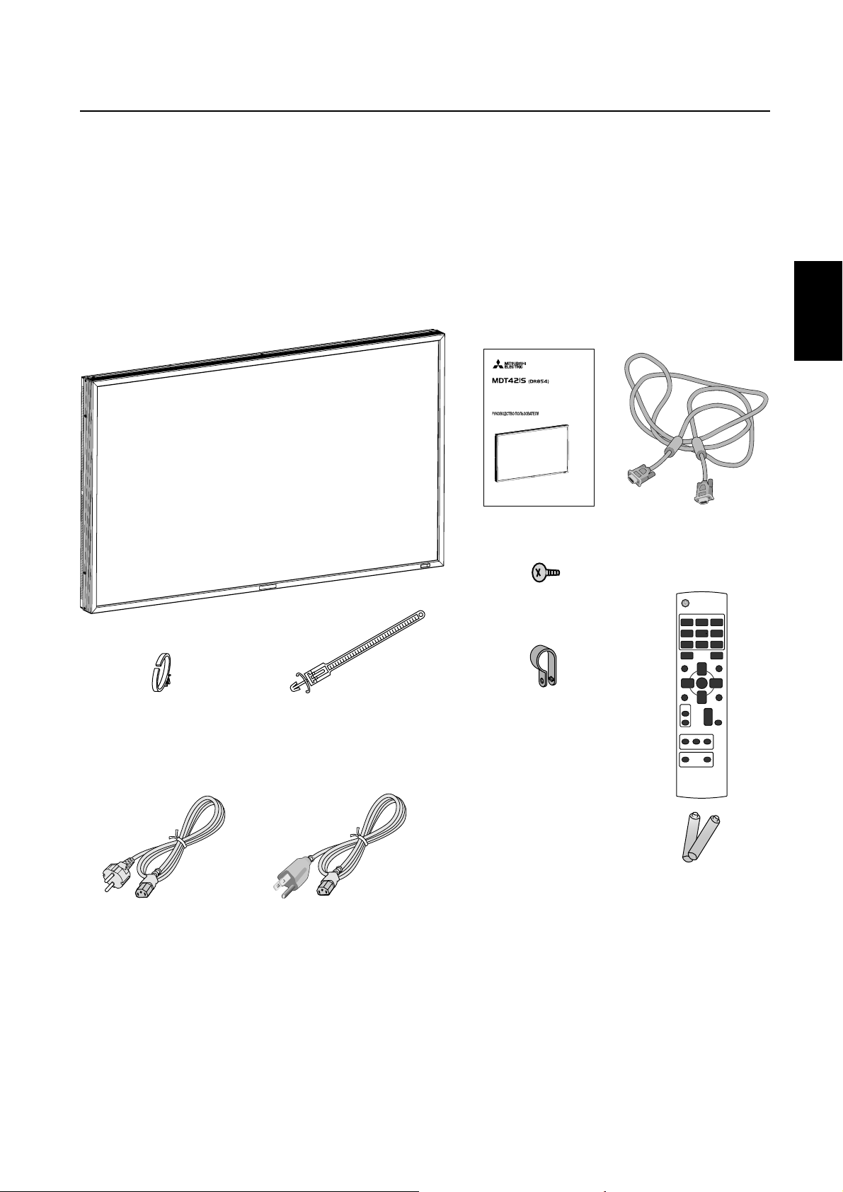
Inhalt der Verpackung
Der Karton* Ihres LCD-Monitor MDT421S enthält folgende Komponenten:
• LCD-Monitor
• Netzkabel (3 m)
• Signalkabel (4 m)
• Bedienungsanleitung
• Fernbedienung und Mignon-Batterien (Größe AAA)
• Klemme (2 Stück) (zur Verhinderung eines Herunterfallens)
• Klemme (3 Stück) (zur Sicherung der Kabel)
• Klemme (2 Stück) (zur Sicherung des Netzkabels, HDMIKabels und Display Port-Kabels)
• Schraube für die Klemme (zur Verhinderung eines Herunterfallens) x 2
42" LCD Display Monitor
USER’S MANUAL
BEDIENERHANDBUCH
MANUAL DEL USUARIO
MANUEL UTILISATEUR
MANUALE UTENTE
GEBRUIKERSHANDLEIDING
Deutsch
Klemme (3 Stück)
(zur Sicherung der Kabel)
Klemme (2 Stück)
(zur Sicherung des Netzkabels,
HDMI-Kabels und Display Port-Kabels )
* Das Netzkabel wird in landesspezifischer Ausführung mitgeliefert.
Für EU
Für
Nordamerika
Netzkabel
Bedienungsanleitung
Schraube für die Klemme
(M4) x 2
Klemme (2 Stück)
(zur Verhinderung eines
Herunterfallens)
Signalkabel
(Kabel von D-SUB auf D-SUB)
Fernbedienung und
Mignon-Batterien (Größe AAA)
* In allen anderen Ländern ist ein für die Spannung des Stromnetzes
geeignetes und zugelassenes Netzkabel zu verwenden, dass den
Sicherheitsstandards des betreffenden Landes entspricht.
*
Bewahren Sie den Originalkarton und das Verpackungsmaterial für spätere Transporte des Monitors auf.
Folgendes Zubehör ist erhältlich:
• Externe Lautsprecher
• Monitorfußes
• Blende
• CAT5-Satz
Deutsch-5
Page 52

Die Teile und ihre Funktionen
Bedienung und Funktionen des Monitors
ON
OFF
Fernbedienungssensor und Betriebsanzeige
Empfängt das Signal von der Fernbedienung. Vgl. Seite 9.
Leuchtet grün, wenn der LCD-Monitor betriebsbereit ist, und rot,
wenn der LCD-Monitor ausgeschaltet ist. Wenn sich der LCDMonitor im Energiesparmodus befi ndet, leuchtet die LED grün und
rot. Wenn ZEITPLAN aktiviert wurde, blinkt sie grün und leuchtet
rot. (Vgl. Seite 21.) Bei Erkennung eines Fehlers blinkt die LED rot.
Netzschalter ( )
Schaltet den Monitor ein bzw. aus. Vgl. Seite 20.
Taste MUTE
Schaltet die Stummschaltung ein bzw. aus.
Taste INPUT
Zeigt das Bildschirmmenü (
Videoeingangs an.
(Mit Hilfe der Tasten AUF ( ) und AB ( ) kann zwischen
[RGB1], [RGB2], [RGB3], [RGB4], [RGB5]*, [RGB6], [DVD/HD],
[VIDEO<S>] und [VIDEO] umgeschaltet werden.)
* : [RGB 5] lässt sich wählen, wenn die optionale CAT5 Rx
BOX angebracht ist.
Durch Drücken dieser Taste während der Anzeige des
Bildschirmmenüs (OSD-Menüs) können Sie sich in den
Menüoptionen vorwärts bewegen.
OSD-Menü
) zur Umschaltung des
(Siehe Seite 23.)
Plustaste (+)
Dient als Taste (+), mit der Sie bei Verwendung des OSDMenüs den Wert einer Einstellung erhöhen können. Wenn das
OSD-Menü deaktiviert ist, erhöht diese Taste die Lautstärke.
Minustaste (-)
Dient als Taste (-), mit der Sie bei Verwendung des OSDMenüs den Wert einer Einstellung senken können. Wenn das
OSD-Menü deaktiviert ist, reduziert diese Taste die Lautstärke.
Taste AUF ( )
Aktiviert das OSD-Menü, wenn es deaktiviert ist.
Dient als Taste
Menüs die Markierung nach oben zur gewünschten Einstellung verschieben können.
, mit der Sie bei Verwendung des OSD-
Deutsch-6
Taste AB ( )
Aktiviert das OSD-Menü, wenn es deaktiviert ist.
Dient als Taste
Menüs die Markierung nach unten zur gewünschten Einstellung verschieben können.
, mit der Sie bei Verwendung des OSD-
Taste EXIT
Drücken Sie die EXIT-Taste, um das Bildschirmmenü (OSDMenü) zu öffnen, falls es noch nicht angezeigt wird.
Durch Drücken dieser Taste während der Anzeige des
Bildschirmmenüs (OSD-Menüs) können Sie sich in den
Menüoptionen rückwärts bewegen.
(Mit der INPUT-Taste können Sie sich in den Menüoptionen
vorwärts bewegen.) Wenn Sie diese Taste im Hauptmenü
drücken, wird das Bildschirmmenü (
(siehe Seite 23).
OSD-Menü
) geschlossen
Helligkeitssensor (vorn, hinten)
Sensor für die Helligkeitsautomatik. (Siehe Seite 25 und 33.)
Hauptnetzschalter
Schalter zum Ein- und Aus-Schalten der Netzspannung.
HINWEIS:
Diese Funktion sperrt den Zugriff auf alle Funktionen der
Bedientasten. Um die Bedientasten-Sperrfunktion zu aktivieren, drücken Sie gleichzeitig die Tasten „
halten diese länger als drei Sekunden gedrückt. Um wieder in
den Bedienmodus umzuschalten, drücken Sie gleichzeitig die
Tasten „
den gedrückt.
Bedientasten-Sperrmodus
“ und „ “ und
“ und „ “ und halten diese länger als drei Sekun-
Page 53

Anschlüsse
(OUT)
(IN)
(OUT)
(IN)
(IN)
(IN)
Deutsch
CAT5 Rx BOX Einschubrahmen
Die CAT5 Rx BOX (Option) wird in diesen Einschubrahmen
eingesteckt. (Siehe Seite 12.)
HINWEIS:
Schließen Sie auf keinen Fall Netzwerkgeräte an die CAT5 INund OUT-Stecker an. Andernfalls können sie sich gegenseitig
ungünstig beeinfl ussen und eine Störung verursachen.
EXTERNAL CONTROL (Mini-D-SUB-Anschluss, 9-polig)
Schließen Sie den IN-Anschluss am RS-232C OUT-Anschluss
des Computers oder eines mehrfach angeschlossenen
MDT421S-Monitors an.
Verbinden Sie den Ausgang (OUT) mit dem seriellen Eingang
(RS-232C IN) an einem MDT421S- oder MDT521S-Monitor in
der Kette.
VIDEO IN/OUT
VIDEO IN-Anschluss (BNC und RCA): Eingang für ein ge-
mischtes Videosignal. BNC und RCA können nicht gleichzeitig
genutzt werden. (Verwenden Sie nur eine Eingangsart.)
VIDEO OUT-Anschluss (BNC): Ausgang für das gemischte
Videosignal von der VIDEO IN-Quelle.
S-VIDEO IN-Anschluss (MINI-DIN, 4-polig): Eingang für
S-Video (Y/C, separates Signal).
RGB 4 IN / DVD/HD -Anschluss (BNC)
Eingang für analoge RGB-Signale von einem Computer oder
einem anderen RGB-Gerät.
Zum Anschluss eines Geräts (z. B. DVD-Player, HDTV-Gerät
oder Laser-Disk-Player). Vgl. Seite 16, 18.
EXTERNAL SPEAKER TERMINAL
Ausgang fur das Audiosignal fur externe Lautsprecher von
den Anschlussbuchsen AUDIO 1, 2, 3 oder HDMI.
AUDIO OUT
Ausgang für Audiosignale von den Anschlussbuchsen AUDIO
1, 2, 3 oder HDMI.
AUDIO IN 1, 2, 3
Eingang für das Audiosignal von externen Geräten wie etwa
Computern, Videorekordern oder DVD-Playern.
RGB 1 IN (HDMI)
Für den Eingang digitaler RGB-Signale eines Computers,
DVD-Spielers usw.
* Dieser Anschluss unterstützt keine analogen Eingangssignale.
Die AUDIO-Funktion wird über HDMI unterstützt.
RGB 2 IN (DVI-D)
Eingang für digitale RGB-Signale von einem Computer.
* Dieser Anschluss unterstützt keine analogen Eingangssignale.
Die AUDIO-Funktion wird über DVI-D unterstützt.
RGB 3 IN (Mini-D-SUB-Anschluss, 15-polig)
Eingang für analoge RGB-Signale von einem Computer oder
anderem RGB-Gerät.
RGB OUT-Anschluss (Mini-D-SUB-Anschluss,
15-polig)
Voor de uitvoer van het geluidssignaal via de aansluiting RGB
3, 4 oder 5 IN.
Wechselstromeingang (AC IN)
Hier wird das mitgelieferte Netzkabel angeschlossen.
RGB 6 IN (DISPLAY PORT)
Eingang für digitale RGB-Signale von einem Computer.
Deutsch-7
Page 54

Fernbedienung
Netzschalter
Schaltet den Monitor ein bzw. aus.
* Wenn die LED-Betriebsanzeige des Monitors nicht leuchtet,
funktionieren die Bedienelemente der Fernbedienung nicht.
Taste INPUT
Dient zur Auswahl des Eingangssignals [RGB1] (HDMI),
[RGB2] (DVI-D), [RGB3] (D-SUB), [RGB4] (BNC), [RGB5]*
(CAT5), [RGB6] (DISPLAY PORT), [DVD/HD] (YPbPr),
[VIDEO<S>] und [VIDEO].
* : [RGB 5] lässt sich wählen, wenn die optionale CAT5 Rx
BOX angebracht ist.
Taste PICTURE MODE
Dient zur Auswahl des Bildmodus [HIGHBRIGHT],
[STANDARD], [sRGB], [CINEMA]. Vgl. Seite 21.
HIGHBRIGHT: für bewegliche Bilder, wie z.B. Video
STANDARD: für Bilder (Werkseitige Einstellung)
sRGB: für textbasierte Bilder
CINEMA: für Filme
Taste DISPLAY
Blendet das Informations-OSD ein bzw. aus. Vgl. Seite 22.
Taste SET
Dient als Taste SET für das OSD-Menü.
Minustaste
Dient als Taste (-), mit der Sie bei Verwendung des OSDMenüs den Wert einer Einstellung senken können. Kleiner
Bildschirm zur Einstellung des „BIB“-Modus wird nach links
verschoben.
Taste AUTO SETUP
Aktiviert das Menü AUTOM. EINRICHTUNG. Vgl. Seite 28.
Deutsch-8
Taste AUDIO INPUT
Hiermit wird die Audio-Quelle der einzelnen Video-Quellen
umgeschaltet. Die Audio-Quelle wird zwischen [AUDIO1],
[AUDIO2], [AUDIO3] und [HDMI] in dieser Reihenfolge
umgeschaltet. Beachten Sie bitte, dass Sie keine Audio-Quelle
für [VIDEO<S>] oder [VIDEO] auswählen können. [HDMI]
kann nur dann ausgewählt werden, wenn es sich bei der
Video-Quelle um [RGB 1] handelt.
Taste PIP (Bild im Bild)
Taste ON/OFF: PIP-ON/OFF. Vgl. Seite 27, 33.
Taste INPUT: Dient zur Auswahl des „Bild-im-Bild“-
Eingangssignals.
Taste CHANGE: Tauscht das Hauptbild gegen das Teilbild
aus und umgekehrt.
Hinweis:
Die „PIP“- und „POP“-Modi funktionieren nicht, wenn die
Bildschirmgrose „CUSTOM“ (Anwender) oder „REAL“ (Echt)
ist.
Taste STILL
Taste ON/OFF: Schaltet den Standbildmodus ein bzw. aus.
Taste CAPTURE: Aktualisiert das Standbild.
Taste SIZE
Dient zur Auswahl der Darstellungsgröße FULL, NORMAL,
CUSTOM, DYNAMIC und REAL. Vgl. Seite 21.
Taste MENU
Schaltet den Menümodus ein bzw. aus.
Taste AUF
Dient als Taste , mit der Sie bei Verwendung des
OSD-Menüs die Markierung nach oben zur gewünschten
Einstellung verschieben können.
Kleiner Bildschirm zur Einstellung des „BIB“-Modus wird nach
oben verschoben.
Plustaste
Dient als Taste (+), mit der Sie bei Verwendung des OSDMenüs den Wert einer Einstellung erhöhen können.
Kleiner Bildschirm zur Einstellung des „BIB“-Modus wird nach
rechts verschoben.
Taste EXIT
Mit dieser Taste kehren Sie bei Verwendung des OSD-Menüs
zum vorherigen Menü zurück.
Taste AB
Dient als Taste , mit der Sie bei Verwendung des OSDMenüs die Markierung nach unten zur gewünschten
Einstellung verschieben können.
Kleiner Bildschirm zur Einstellung des „BIB“-Modus wird nach
unten verschoben.
Taste MUTE
Schaltet die Stummschaltung ein bzw. aus.
Taste VOLUME
Erhöht oder vermindert den Audiosignalpegel.
Page 55

< Reichweite der Fernbedienung >
Richten Sie die Vorderseite der Fernbedienung bei der
Tastenbenutzung auf den Fernbedienungssensor des
LCD-Monitors.
Sie können die Fernbedienung in einem Abstand von etwa
7 m von der Vorderseite des Fernbedienungssensors am
LCD-Monitor verwenden. Bei einem Abstand von maximal 3
m kann die Fernbedienung in einem horizontalen bzw.
vertikalen Winkel bis 30° eingesetzt werden.
30° 30°
Deutsch
VORSICHT:
Wenn der Fernbedienungssensor am LCD-Monitor von
direktem Sonnenlicht oder starkem Licht angestrahlt oder von
einem Gegenstand verdeckt wird, funktioniert die Fernbedienung möglicherweise nicht.
< Umgang mit der Fernbedienung >
* Schützen Sie die Fernbedienung vor starken Stößen.
* Schützen Sie die Fernbedienung vor Wasser oder anderen
Flüssigkeiten. Falls die Fernbedienung nass wird, trocknen
Sie sie umgehend ab.
* Schützen Sie die Fernbedienung vor Hitze und Dampf.
* Öffnen Sie die Fernbedienung nur zum Einsetzen der
Batterien.
Deutsch-9
Page 56

Einrichten des LCD-Monitors
1. Wählen Sie den Installationsstandort.
VORSICHT:
INSTALLIEREN SIE DEN LCD-MONITOR KEINESFALLS ALLEINE.
Die Installation des LCD-Monitors muss von einem qualifi -
zierten Techniker durchgeführt werden. Weitere Informationen
erhalten Sie bei Ihrem Händler.
VORSICHT:
ZUM AUFSTELLEN ODER VERSCHIEBEN DES LCD-MONITORS SIND MINDESTENS ZWEI PER SONEN NÖTIG.
Andernfalls kann es zu Verletzungen führen, falls der LCDMonitor hinunterfällt.
VORSICHT:
Bei Montagearbeiten oder Betrieb darf der Monitor keinesfalls
auf dem Kopf stehen oder sein Bildschirm nach unten weisen.
VORSICHT:
Installieren Sie den LCD-Monitor nicht an einem Ort, an dem
er direktem Sonnenlicht ausgesetzt ist, das dies zu Fehlern in
der Anzeige fuhren kann.
VORSICHT:
Dieses LCD ist mit einem Temperaturfühler und einem Ventilator ausgestattet. Wenn das Gerät zu heiß wird, schaltet sich
der Ventilator automatisch ein. Bei einer eventuellen Überhitzung trotz laufenden Ventilators wird das Menü „Vorsicht“
angezeigt. Unterbrechen Sie in diesem Falle die Benutzung,
bis das Gerät sich abgekühlt hat. Wenn der LCD-Monitor in einem Gehäuse oder mit einem Schutz für die LCD-Oberfl äche
verwendet wird, überprüfen Sie bitte die Innentemperatur des
Monitors mithilfe des HEAT STATUS (WÄRMEZUSTAND) (siehe
Seite 31). Wenn die Temperatur über dem Normalzustand
liegt, schalten Sie unter SCREEN SAVER (BILDSCHIRMSCHONER) den Ventilator ein (siehe Seite 28).
WICHTIG:
Legen Sie die Schutzfolie, in die der LCD-Monitor eingewickelt war, unter den Monitor, um Kratzer zu vermeiden.
• Legen Sie Mignon-Batterien (Größe AAA) so ein, dass die
Plusund Minuszeichen auf den Batterien mit den entsprechenden Markierungen im Batteriefach übereinstimmen.
• Verwenden Sie Batterien derselben Marke.
• Verwenden Sie neue und gebrauchte Batterien nicht
gleichzeitig. Dies verkürzt die Lebensdauer und kann zum
Auslaufen der Batterien führen.
• Nehmen Sie leere Batterien sofort heraus, um ein Auslaufen der Batterien im Batteriefach zu vermeiden.
Vermeiden Sie Kontakt mit Batteriefl üssigkeit, da dies zu
Hautreizungen führen kann.
HINWEIS:
Wenn Sie wissen, dass Sie die Fernbedienung längere Zeit nicht
benutzen werden, sollten Sie die Batterien herausnehmen.
3. Schließen Sie externe Geräte an. (Siehe
Seiten 15-19.)
• Schalten Sie den Monitor zum Schutz der angeschlossenen Geräte am Hauptnetzschalter aus, bevor Sie Geräte
anschließen.
• Befolgen Sie die Anweisungen in der Bedienungsanleitung
des entsprechenden Geräts.
4. Schließen Sie das mitgelieferte
Netzkabel an.
• Die verwendete Steckdose sollte sich möglichst in der
Nähe des Geräts befi nden und leicht zugänglich sein.
• Stecken Sie den Stecker fest in die Steckdose. Lose
Steckverbindungen können Störungen verursachen.
HINWEIS:
Beachten Sie zur Auswahl des richtigen Netzkabels den Abschnitt
„Sicherheitsvorkehrungen, Pfl ege und Einsatzempfehlungen“ in
dieser Bedienungsanleitung.
2. Einlegen und Entnehmen der Batterien
Die Fernbedienung benötigt 1,5V-Mignon-Batterien (Größe
AAA).
So legen Sie Batterien ein bzw. tauschen sie aus:
Vorgehensweise zum Einlegen der Batterien
1. Entriegeln Sie die Abdeckung und ziehen Sie sie in Pfeilrichtung auf.
2. Legen Sie die Batterien entsprechend der (+)- und (–)-
Markierungen im Gehäuse ein.
3. Bringen Sie die Abdeckung wieder an.
Vorgehensweise zur Entnahme der Batterien
1. Entriegeln Sie die Abdeckung und ziehen Sie sie in Pfeilrichtung auf.
2. Nehmen Sie die Batterien heraus.
VORSICHT:
Die falsche Verwendung von Batterien kann dazu führen,
dass die Batterien auslaufen oder explodieren.
Beachten Sie besonders folgende Punkte:
Deutsch-10
Klemme
Verwenden Sie die
Klemme, um das
Kabel fest zu sichern.
5. Schalten Sie die Stromversorgung aller
angeschlossenen externen Geräte ein.
Wenn die Geräte an einen Computer angeschlossen sind,
schalten Sie zuerst den Computer ein.
Page 57

6. Bedienen der extern angeschlossenen
Geräte
Sie können sich das Signal zum gewünschten Gerät anzeigen
lassen.
7. Stellen Sie die Lautstärke ein.
Ändern Sie die Einstellungen je nach Bedarf durch Vermindern
oder Erhöhen der Lautstärke.
8. Justieren Sie den Bildschirm. (Siehe
Seiten 24-34.)
Korrigieren Sie, falls nötig, die Bildposition bzw. die Konfi gu-
ration.
Anbringen des Monitorfußes
1. Schalten Sie den Monitor aus.
2. Die Schrauben an beiden Seiten des Monitors anziehen.
HINWEIS:
Die Monitorfußes so anbringen, dass die längeren Stücke
nach vorne kommen.
Entfernen des Monitorfußes
1. Breiten Sie die Schutzfolie auf einer ebenen Oberfl äche
wie etwa einem Tisch aus.
2. Legen Sie den Monitor auf die Schutzfolie.
3. Entfernen Sie die Schrauben mit einem Schraubendreher
und verwahren Sie sie für den späteren Gebrauch.
Deutsch
9. Justieren Sie das Bild. (Siehe Seiten
24-34.)
Ändern Sie, falls nötig, die Einstellungen für Helligkeit oder
Kontrast.
10. Empfohlene Einstellungen
Um Bildschatten zu vermeiden, nehmen Sie je nach
Anwendung folgende Einstellungen vor: ENERGIESPAREN
(vgl. Seite 28), BILDSCHIRMSCHONER (vgl. Seite 28),
SEITENRANDFARBE (vgl. Seite 28), DATUM UND ZEIT (vgl.
Seite 31), ZEITPLAN (vgl. Seite 31).
11. Anbringen und Entfernen des
Monitorfußes
Der Monitorfuß steht als Option zur Verfügung.
Näheres über die Monitorfüße ist aus der Bedienungsanleitung ersichtlich.
12. Anschluss des HDMI-Kabels und
Display Port-Kabels
Klemme
Verwenden Sie die
Klemme, um das
Kabel fest zu sichern.
Monitorfußes
(Das längere Stück
kommt nach vorne.)
Schraubenlöcher
für MDT421S
Deutsch-11
Page 58

13. Wenn der MDT421S im Hochformat
installiert wurde
Voraussetzungen
Der MDT421S kann im Hochformat installiert werden. Dabei
sollten jedoch die folgenden Punkte beachtet werden.
Vorsicht:
Der Monitor kann nur dann im Hochformat installiert werden,
wenn er an der Wand oder an der Decke angebracht wird.
Der Monitorfuß kann nicht an den Monitor angebracht
werden, wenn dieser im Hochformat installiert wurde.
Das Anordnung des Bildschirms im Hochformat verkürzt die
durchschnittliche Lebensdauer der LCD Hintergrundbeleuchtung.
Der Monitor sollte nur innerhalb der unten beschriebenen
Betriebsumgebung (Temperatur) betrieben werden:
Betriebsumgebung:
Temperatur 5 - 35 °C / 41 - 95 °F
Feuchtigkeit 20 - 80 % (ohne Kondensation)
Bitte richten Sie das Produkt lediglich in der vorgegebenen
Position wie unten gezeigt ein:
Richten Sie es nicht umgekehrt ein.
Optionale Lautsprecher (SP-421S) können nicht angeschlossen werden, wenn der LCD-Monitor im Hochformat
installiert wurde.
Einrichtung
Der linke Rand des Querformats (von vorne betrachtet)
muss nach oben zeigen.
Querformat
Im Uhrzeigersinn Gegen den Uhrzeigersinn
90°
90°
14. Kabelverbindung mit dem CAT5Adapter
HINWEIS:
Der CAT5-Satz ist eine für den MDT421S entwickelte Option.
Details zur Montage fi nden Sie im Benutzerhandbuch des
CAT5-Satzes (Option).
CAT5-Videoverbindung
Die CAT5-Videoverbindungsfunktion dient zur Übertragung
des analogen RGB-Videosignals des Computers und des
Steuersignals des Monitors über große Entfernung mittels
CAT5-Kabeln. Der Monitor kann mit der optionalen CAT5 Tx
BOX und der am MDT421S angebrachten CAT5 Rx BOX über
den Computer gesteuert werden.
VORSICHT:
Schließen Sie auf keinen Fall Netzwerkgeräte (wie einen Hub
und einen an das LAN angeschlossenen Computer) an die
CAT5 IN- und OUT-Stecker des CAT5-Satzes an. Sollten
diese Geräte dennoch angeschlossen werden, können diese
sowie die CAT5 Tx BOX, die CAT5 Rx BOX und der Monitor
beschädigt werden.
1. USB Treiber Installation für CAT5
serielle Kommunikationskontrolle
Um den Computer und die CAT5 Tx BOX über eine USBSchnittstelle anschließen zu können, müssen Sie den USBTreiber von der im CAT5-Satz (Option) enthaltenen CD auf
Ihrem Computer installieren. (Bei Verbindung von Computer
und Konverter CAT5 Tx BOX über die RS-232C-Schnittstelle
ist die Installierung des USB-Treibers nicht erforderlich.)
Unterstützte Betriebssysteme: Windows
Installierung:
1) Installierung bei Windows
Öffnen Sie die Datei „PL2303-Driver_XP2K_v******.exe“ im
Windows XP Ordner auf der CD-ROM, die Sie mit dem CAT5Satz (Option) erhalten haben, und installieren Sie den Treiber
gemäß den auf dem Bildschirm angezeigten Anweisungen.
2) Installierung bei Windows Vista
Öffnen Sie die Datei „PL2303_Prolifi c_Vista_******.exe“ im
Windows VISTA Ordner auf der CD-ROM, die Sie mit dem CAT5Satz (Option) erhalten haben, und installieren Sie den Treiber
gemäß den auf dem Bildschirm angezeigten Anweisungen.
®
XP
®
XP, Windows Vista®
®
MDT421S
MDT421S
Deutsch-12
2. Konfi gurierung der CAT5-
Videoverbindungsfunktion
Es gibt zwei Fälle der Konfi gurierung.
1) Verbindung mit einem Monitor
Computer
USB-Kabel
CAT5-Kabel
CAT5 Tx BOX
(Option)
VGA-Kabel (Mini-D-SUB, 15-polig) (mitgeliefert)
Monitor mit CAT5
Rx BOX (Option)
Page 59

1. Verbinden Sie den USB-Anschluss am mitgelieferten
Konverter CAT5 Tx BOX mit dem am Computer über ein
handelsübliches USB-Kabel. (Ist der USB-Treiber nicht
verfügbar, so nutzen Sie ein RS-232C-Kabel neben einem
USB-Kabel zur Verbindung. In diesem Fall dient das USBKabel zur Stromversorgung des Konverters CAT5 Tx
BOX.) Vgl. Seite 35.
2. Verbinden Sie den D-SUB-Eingang an Konverter CAT5 Tx
BOX und den VGA-Ausgang (D-SUB) am Computer über
das Signalkabel (Mini-D-SUB, 15-polig), das zum Lieferumfang des Monitors gehört.
3. Schließen Sie ein handelsübliches CAT5-Kabel an den
modularen Steckverbinder der CAT5 Tx BOX und den
CAT5 (RGB5) IN-Stecker der CAT5 Rx BOX an.
2) Verbindung mit mehreren Monitoren
Computer
VGA-Kabel (Mini-D-SUB, 15-polig)
(mitgeliefert)
USB-Kabel
CAT5 Tx BOX
(Option)
CAT5-Kabel
CAT5-Kabel
Monitor mit CAT5
Rx BOX (Option)
Monitor, der
Mitsubishi CAT5
unterstützt
3. Verschiedene Einstellungen beim
CAT5-Videoanschluss
Beim CAT5-Videoanschluss sind die nachstehenden Einstellungen auf dem Menübildschirm zu konfi gurieren. (Siehe Seite
29.)
1) CAT5 CABLE LENGTH
Wählen Sie die Kabellänge, woraufhin die Vorgaben für alle
Einstellwerte automatisch bestimmt werden. Wählen Sie den
Wert, der der tatsächlichen Läge Ihres Kabels am nächsten
kommt.
2) CAT5 EQ
Stellen Sie diesen Parameter so ein, dass die angezeigten
Texte und Grafi ken möglichst wenig verschwommen und
verschmiert erscheinen.
3) CAT5 R-GAIN/G-GAIN/B-GAIN
Erscheint das Anzeigebild zu dunkel, so erhöhen Sie die
einzelnen Werte. Werden die Weißtöne nicht nach Wunsch
angezeigt, so stellen Sie die Werte von R-GAIN und B-GAIN
entsprechend ein.
4) CAT5 R-SKEW/G-SKEW/B-SKEW
Stellen Sie die einzelnen Werte so ein, dass die Farbabweichung bei den angezeigten Computer-Texten und -Grafi ken auf
ein Mindestmaß beschränkt ist.
Deutsch
1. Zusätzlich zum Vorgehen in Schritt 1) oben verbinden Sie
den CAT5-Ausgang (OUT) des ersten Monitors und den
CAT5-Eingang (RGB5 IN) am zweiten Monitor über eine
handelsübliches CAT5-Kabel.
2. Der dritte und eventuell weitere Monitore sind in derselben
Weise anzuschließen. Der Anschluss von bis zu 5 Monitoren ist möglich.
Zulässige Kabellänge
Verbindung Max. Kabel/Signalzeitsteuerung
Ein Monitor 150 m/1920 x 1080 bei 60 Hz
Mehrere Moni-
tore
Die o. a. Längen beruhen auf tatsächlichen Messungen
mithilfe unserer Standard-Signalquelle und dem empfohlenen
Kabel wie folgt. Vor der Aufstellung prüfen Sie die Funktion
des Monitors durch dessen Verbindung mit dem Computer
und den Kabeln.
Empfohlenes Kabel :
8-pin Stecker, nicht gekreutzt, abgeschirmt CAT5 oder CAT5e
Handelsübliche Kabel, die den Konformitätstest bestanden
haben (mit handelsüblichen abgeschirmten Steckverbindern
getestet) :
7929A von Belden, NFTP-C5e-GY von Nex1
200 m/1920 x 1080 bei 60 Hz
(Gesamtlänge der Verbindungskabel)
Deutsch-13
Page 60

Montage und Anbringung von Zubehör am LCD-Monitor
Es gibt zwei Möglichkeiten, Montagezubehör am LCD-Monitor
anzubringen:
1. Bei aufrecht stehendem Monitor
Bei auf der Vorderseite liegendem Monitor
2.
Legen Sie die Schutzfolie, in die der LCD-Monitor beim Transport eingewickelt war, unter den Bildschirm, um ein Verkratzen der Bildschirmoberfl äche zu vermeiden.
Dieses Gerät kann ohne Monitorfuß oder anderes Montagezubehör nicht benutzt oder installiert werden. Bei Nichteinhaltung der erforderlichen Montageanleitungen kann es zu
Schäden am Gerät oder Verletzungen des Benutzers kommen. Die Produkthaftung deckt durch unsachgemäße Installation entstandene Schäden nicht ab. Nichtbeachtung dieser
Empfehlungen kann zum Erlöschen des Garantieanspruchs
führen.
Verwenden Sie Montageschrauben M6 (10 mm länger als
die Dicke des Montagearms) und ziehen Sie sie fest an.
Federringe o.ä. verwenden, um zu verhindern, dass sich die
Schrauben lösen können. MITSUBISHI ELECTRIC empfi ehlt
die Verwendung eines Montageadapters, der dem TÜV-GS
und/ oder dem UL1678-Standard für Nordamerika entspricht.
482.8 482.8
100 100 100100
3. Belüftungsanforderungen bei EinbauMontage
Halten Sie die im nachfolgenden Diagramm angegebenen
Abstände zur Umbauung ein, damit die Wärme entweichen
kann.
4. Um ein Herunterfallen des Monitors zu
verhindern
Verwenden Sie bei der Installation des Monitors den Monitorfuß (optional), damit der Monitor im Fall eines Erdbebens oder
anderen Unglücks nicht umfällt und die Wahrscheinlichkeit
von Personen- und Sachschäden verringert wird.
Sichern Sie den Monitor wie in der Abbildung dargestellt unter
Verwendung eines für das Gewicht des Monitors ausreichend
starken Seils (im Handel erhältlich) an einer massiven Wand
oder massiven Strebe. (MDT421S: etwa. 27 kg) (mit dem
optionalen Monitorfuß))
Wenn Sie Schraubenhaken (im Handel erhältlich) verwenden,
empfehlen wir Ihnen den Einsatz von ringförmigen und nicht
C-förmigen (offenen) Schraubenhaken.
400 mm
Gewinde-
bohrungen
Schraubenhaken o. Ä.,
im Handel erhältlich
279.3279.3
100100
(mm)
Stabile Unterlage Griffe Schutzfolie
Vorsicht:
Verhinderung eines Herunterfallens des Monitors.
• Die Installation des Monitors mit Metallhalterungen für
eine Wand- oder Deckeninstallation (im Handel erhältlich)
erfolgt auf eigene Verantwortung. Lesen Sie hinsichtlich
des detaillierten Installationsverfahrens die Anleitung im
Lieferumfang der Metallhalterungen.
• Konsultieren Sie bei Fragen hinsichtlich des Installationsortes den Hersteller der Halterungen, um die Wahrscheinlichkeit von Personen- oder Sachschäden aufgrund
eines Herunterfallens des Monitor im Falle eines Erdbebens oder anderen Unglücks zu verringern.
• Um das Risiko zu vermindern, dass der Bildschirm herunterfällt, ziehen Sie ein handelsübliches Seil durch die Griffe
rechts und links vom Bildschirm und sichern Sie es an den
Wand- oder Deckenhalterungen.
• Legen Sie sich auf keinen Fall dort schlafen, wo Sie durch
ein Umkippen oder Herunterfallen des Monitors im Falle
eines Erdbebens oder anderen Unglücks getroffen werden
könnten.
Seil o. Ä.,
im Handel erhältlich
Klemme
Vorsicht:
• Das Risiko, dass der Monitor herunterfällt, hängt von
der Stärke der Klammern sowie vom Untergrund ab, auf
der das Gerät zur Verhinderung eines Herunterfallens
angebracht ist. Wenn Sie keine ausreichende Tragkraft
sicherstellen können, sorgen Sie bitte für eine adäquate
Verstärkung.
• Auch wenn die empfohlene Funktion zur Verhinderung
eines Herunterfallens darauf gerichtet ist, das Risiko eines
Unfalls oder von Schäden zu verringern, bietet es jedoch
keine Garantie für den Schutz gegen ein Erdbeben oder
eine Naturkatastrophe.
• Legen Sie sich auf keinen Fall dort schlafen, wo Sie durch
ein Umkippen oder Herunterfallen des Monitors im Falle
eines Erdbebens oder anderen Unglücks getroffen werden
könnten.
• Entfernen Sie vor einem Transport des Monitors das
Seil zur Sicherung desselben. Falls Sie dies unterlassen,
könnte es zu Personenschäden oder einer Beschädigung
des Monitors kommen.
Schraube
Deutsch-14
Page 61

Anschließen von Geräten
Bevor Sie Geräte anschließen:
* Schalten Sie zunächst alle angeschlossenen Geräte aus, und stellen Sie die Verbindungen her.
* Ausführliche Hinweise entnehmen Sie den Handbüchern zu den einzelnen Geräteeinheiten.
Anschlussübersicht
LCD-Monitor
Computer
(analog RGB)
Computer
(DVI-D, DISPLAY PORT)
DVD-Player
(HDMI)
LCD-Monitor (zweiter Monitor)
Deutsch
Stereoverstärker
VCR
(RCA)
Externer Lautsprecher
Deutsch-15
Page 62

Anschluss eines Computers
Wenn Sie Ihren Computer an den LCD-Monitor anschließen, können Sie die Bildschirmanzeige des Computers auf dem Monitor
anzeigen.
Bei einigen Videokarten wird das Bild möglicherweise nicht richtig angezeigt.
Anschluss des LCD-Monitors an einen Computer
• Um den RGB 3 IN-Anschluss (Mini-D-SUB, 15-polig) am LCD-Monitor für den Anschluss zu nutzen, verwenden Sie das mitgelieferte PC-RGB-Signalkabel (Mini-D-SUB, 15-polig auf Mini-D-SUB, 15-polig).
Wählen Sie RGB 3 mit der INPUT-Taste am LCD-Monitor oder der D-SUB-Taste an der Fernbedienung.
• Um den RGB 4-Anschluss (BNC) am LCD-Monitor für den Anschluss zu nutzen, verwenden Sie ein separat erhältliches Signalkabel (Mini-D-SUB, 15-polig auf BNC x 5).
Wählen Sie RGB 4 mit der INPUT-Taste am LCD-Monitor oder der BNC-Taste an der Fernbedienung.
• Wählen Sie für den Audio-Eingang AUDIO IN 1, 2 oder 3 unter Zuhilfenahme der AUDIO INPUT-Taste.
• Verwenden Sie den RGB OUT-Stecker (Mini D-Sub, 15-polig), um einen zweiten LCD-Monitor anzuschließen. (Das vom ersten LCD-Monitor gewählte Signal RGB 3, RGB 4 oder RGB 5 (optional) wird ausgegeben.)
• Über die Buchse AUDIO OUT wird der Ton des ausgewählten Audioeingangs ausgegeben.
BNC x 5
LCD-Monitor
Mini-D-SUB, 15-polig
PC oder IBM-kompatibel
Zu RGB-Ausgang
Mini-D-SUB, 15-polig
Zu Audioausgang
Mini-D-SUB, 15-polig
RCA
LCD-Monitor (zweiter Monitor)
RCA
Mini-D-SUB, 15-polig
Deutsch-16
Page 63

Anschluss an Geräte mit digitaler Schnittstelle
Sie können Geräte anschließen, die mit einer dem DVI-(Digital Visual Interface-) Standard entsprechenden digitalen Schnittstelle
ausgestattet sind.
Anschluss des LCD-Monitors an einen Computer mit digitalem Ausgang
• Die Verbindung mit Eingang RGB 2 IN (DVI-D) am LCD-Monitor erfolgt über ein DVI-D-Kabel. Wählen Sie RGB 2 mit der
INPUT-Taste am LCD-Monitor oder der DVI-D-Taste an der Fernbedienung. Wählen Sie „DVI INPUT MODE“ für „DVI-PC“.
(Siehe Seite 31.)
• Die Verbindung mit Eingang RGB 1 IN (HDMI) am LCD-Monitor erfolgt über ein HDMI-Kabel. Wählen Sie RGB 1 mit der
INPUT-Taste am LCD-Monitor oder der HDMI-Taste an der Fernbedienung. Wählen Sie „HDMI INPUT MODE“ für „HDMI-PC“.
(Siehe Seite 31.)
• Die Verbindung mit Eingang RGB 6 IN (DISPLAY PORT) am LCD-Monitor erfolgt über ein Display Port-Kabel. Wählen Sie
RGB 6 mit der INPUT-Taste am LCD-Monitor oder der DISPLAY PORT-Taste an der Fernbedienung.
• AUDIO IN 1, 2, 3 oder HDMI können als Audioeingänge verwendet werden. Zum Anschließen wählen Sie über die Taste AUDIO INPUT die Einstellung AUDIO 1, 2, 3 oder HDMI. Die Einstellung HDMI ist nur verfügbar, wenn RGB 1 gewählt worden
ist.
• Die Eingangssignale an DVI-D- , HDMI- und DISPLAY PORT-Anschluss lassen sich nicht über den RGB OUT-Anschluss ausgeben.
LCD-Monitor
PC oder IBM-kompatibel
Zu RGB-Ausgang
Deutsch
Zu RGB-Ausgang
HDMI
Zu Audioausgang
DVI-D
HDMI
DVI-D
Zu Audioausgang
DISPLAY
PORT
PC oder IBM-kompatibelPC oder IBM-kompatibel
Zu RGB-Ausgang
DISPLAY PORT
Zu Audioausgang
Deutsch-17
Page 64

Anschluss eines DVD-Players mit Component-/HDMI-/DVI-Ausgang
Wenn Sie einen DVD-Player an den LCD-Monitor anschließen, können Sie DVD-Filme anzeigen.
Weitere Informationen fi nden Sie im Benutzerhandbuch zu Ihrem DVD-Player.
Anschluss des LCD-Monitors an einen DVD-Player
• Um den DVD/HD IN-Anschluss (BNC) am LCD-Monitor zu nutzen, verwenden Sie ein getrennt erhältliches BNC-Anschlusskabel. Um einen DVD-Player mit einer RCA-Buchse an das BNC-Anschlusskabel anzuschließen, benötigen Sie einen BNCauf-RCA-Adapter (nicht im Lieferumfang enthalten).
Wählen Sie DVD-HD mit der INPUT-Taste am LCD-Monitor oder der YPbPr-Taste an der Fernbedienung.
• Die Verbindung mit Eingang RGB 1 IN (HDMI) am LCD-Monitor erfolgt über ein HDMI-Kabel. Wählen Sie RGB 1 mit der
INPUT-Taste am LCD-Monitor oder der HDMI-Taste an der Fernbedienung. Wählen Sie „HDMI INPUT MODE“ für „HDMI-HD“.
(Siehe Seite 31.)
• AUDIO IN 1, 2, 3 oder HDMI können als Audioeingänge verwendet werden. Zum Anschließen wählen Sie über die Taste AUDIO INPUT die Einstellung AUDIO 1, 2, 3 oder HDMI. Die Einstellung HDMI ist nur verfügbar, wenn RGB 1 gewählt worden
ist.
BNC x 3
LCD-Monitor
BNC x 3
HDMI
Zu
Videoausgang
BNC-aufRCA-Adapter
RCA
DVD-Player
Zu Audioausgang LZu Audioausgang
R
RCA
DVD-Player
HDMI
Zu HDMI-Ausgang
HINWEIS:
Der Betrieb der angeschlossenen HDMI-Geräte kann nicht immer sichergestellt werden.
Deutsch-18
Page 65
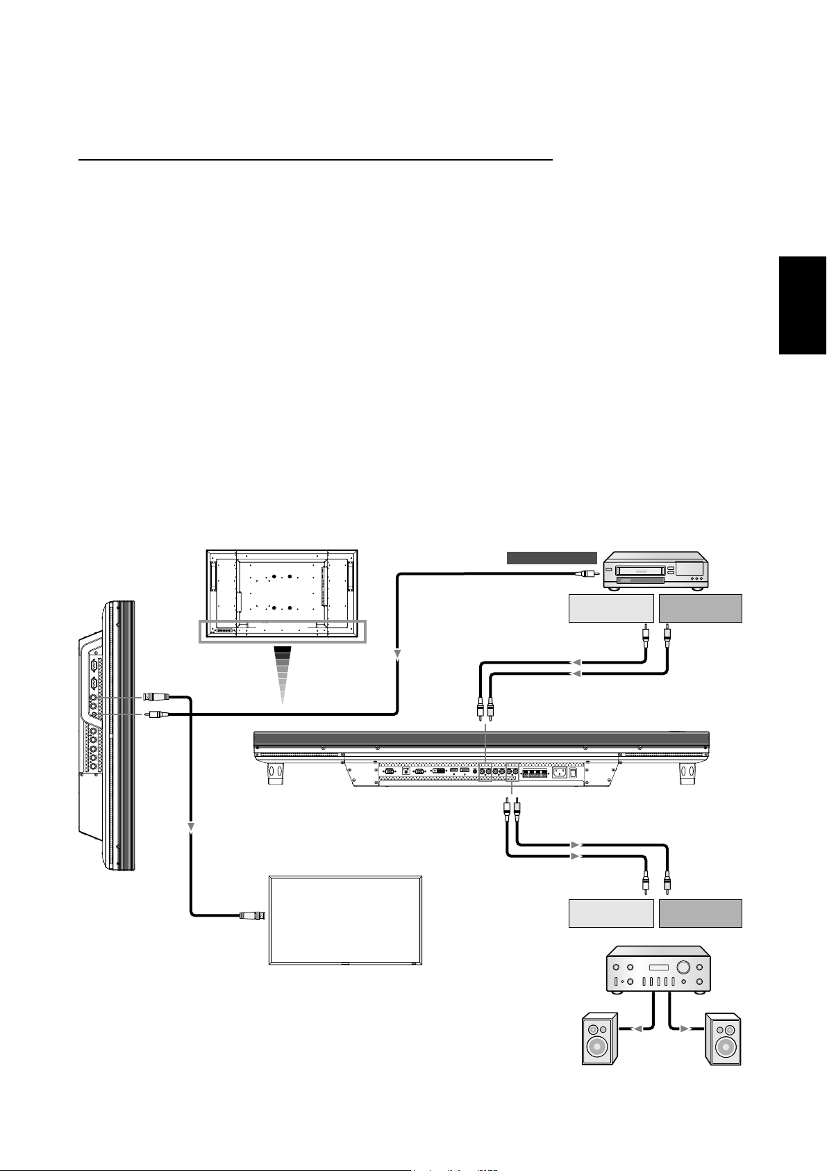
Anschluss eines Videorekorders/Stereoverstärkers
Sie können einen Videorekorder/Stereoverstärker an den LCD-Monitor anschließen. Näheres hierzu fi nden Sie in der Bedienung-
sanleitung von Videorekorder/Stereoverstärker.
Anschluss des LCD-Monitors an einen Videorekorder/Stereoverstärker
• Die Verbindung mit dem Videoeingang VIDEO IN (Cinch, BNC oder S-VIDEO) am LCD-Monitor erfolgt über ein Videokabel
oder S-Videokabel.
Verwenden Sie ein handelsübliches Cinch- oder S-Video-Kabel.
Die Verbindung mit dem Audioeingang AUDIO IN (Cinch) am LCD-Monitor erfolgt über ein Cinch-Kabel.
Beim Beschalten des Cinch- oder BNC-Anschlusses wählen Sie VIDEO mit der INPUT-Taste am LCD-Monitor oder der
VIDEO-Taste an der Fernbedienung.
Beim Beschalten des S-VIDEO-Anschlusses wählen Sie VIDEO<S> mit der INPUT-Taste am LCD-Monitor oder der VIDEO(S)-
Taste an der Fernbedienung.
• Schalten Sie den Stereoverstärker aus, bevor Sie ihn an den LCD-Monitor anschließen.
Verwenden Sie ein RCA-Kabel (Audiokabel) für den Anschluss an den AUDIO OUT-Stecker des LCD-Monitors.
Schließen Sie die Stecker des RCA-Kabels (Audiokabels) richtig an.
Schalten Sie erst den LCD-Monitor und dann den Stereoverstärker ein.
• Das vom LCD-Monitor ausgewählte Audioeingangssignal wird über den AUDIO OUT-Stecker ausgegeben.
HINWEIS:
Verwenden Sie für den Eingang des Videosignals entweder den RCA- oder den BNC-Stecker.
Deutsch
BNC
RCA
LCD-Monitor
LCD-Monitor (zweiter Monitor)
BNC
VCR
Zu Videoausgang
RCA
Zu AudioausgangLZu Audioausgang
R
RCA
RCA
RCA
RCA
Zu AudioeingangLZu Audioeingang
R
Stereoverstärker
Deutsch-19
Externer
Lautsprecher
Page 66

Grundlegende Bedienung
Stromversorgung EIN und AUS
Wenn der LCD-Monitor eingeschaltet ist, leuchtet die Betriebsanzeige grün. In ausgeschaltetem Zustand leuchtet sie rot. Sie
haben die folgenden drei Möglichkeiten, den Monitor ein- und auszuschalten:
1. Sie drücken den Hauptnetzschalter.
HINWEIS:
Wenn Sie den LCD-Monitor über den Hauptnetzschalter
ausschalten, kann der Monitor nicht über Fernbedienung
oder Netzschalter eingeschaltet werden. Sowohl die grüne
als auch die rote Betriebsanzeige ist ausgeschaltet.
Schalten Sie den Hauptnetzschalter auf EIN, bevor Sie
eine der beiden anderen Möglichkeiteneinsetzen.
ON
OFF
Betriebsanzeige
EXITMUTE INPUT
2. Sie drücken den Netzschalter.
HINWEIS:
Bevor Sie den Netzschalter drücken, müssen Sie den
LCD-Monitor am Hauptnetzschalter einschalten.
3. Sie verwenden die Fernbedienung.
HINWEIS:
Bevor Sie die Fernbedienung verwenden, müssen Sie den
LCD-Monitor am Hauptnetzschalter einschalten.
Deutsch-20
Page 67

Betriebsanzeige
Status
Stromversorgung EIN Grün
Stromversorgung AUS Rot
Standby-Modus bei
aktiviertem ZEITPLAN
Standby-Modus Rot, Grün
Diagnose (Fehlererkennung)
Rot an
Grün blinkt
Rotes Blinklicht
Vgl. „Fehlerbehebung“ auf
*
Seite 38.
Verwendung der Energiesparfunktionen
Der LCD-Monitor entspricht der VESA-geprüften DPM Power
Management-Funktion.
Die Power Management-Funktion ist eine Energiesparfunktion, die den Stromverbrauch des Bildschirms automatisch
reduziert, wenn Tastatur oder Maus für einen festgelegten
Zeitraum nicht benutzt wurden.
Die Energiesparfunktion des Bildschirms wurde auf „EIN“
gestellt. Dies ermöglicht dem Bildschirm, in den Energiesparmodus zu wechseln, wenn kein Bildsignal anliegt. Damit
kann die Lebensdauer des Geräts deutlich erhöht und die
Leistungsaufnahme verringert werden.
Auswahl einer Signalquelle
So zeigen Sie Signalquellen an:
Verwenden Sie die Taste INPUT, um [VIDEO] einzustellen.
Verwenden Sie das Menü FARBSYSTEM, um entsprechend
dem Videoformat [AUTO], [NTSC], [PAL], [SECAM], [PAL60]
oder [4.43NTSC] einzustellen.
Darstellungsgröße (PICTURE SIZE)
NORMAL: Anzeige entsprechend dem Seitenverhältnis des
Eingangssignals bei PC-Signal oder Anzeige im Verhältnis 4:3
bei DVD/HD- oder VIDEO-Signal.
FULL (VOLLBILD): Anzeige auf dem gesamten Bildschirm.
DYNAMIC (DYNAMISCH): Bilder des Formats 4:3 werden in
nicht linearer Weise auf Bildschirmgröße gestreckt. (Die Bildränder werden bei der Vergrößerung teilweise beschnitten.)
CUSTOM (ANWENDER)(ZOOM): Bild kann über den aktiven
Anzeigebereich hinaus gestrecktwerden. Die außerhalb des
aktiven Anzeigebereichs liegenden Bildteile sind nicht sichtbar.
REAL (Echt): Das Bild wird in der Aufl osung von 1 zu 1 Pixel
agezeigt.
ZOOM
ZOOM
Bildmodus (PICTURE MODE)
RGB 1, 2, 3, 4, 5, 6
DVD/HD, VIDEO<S>,
VIDEO
HIGHBRIGHT
HIGHBRIGHT
STANDARD
STANDARD
sRGB
CINEMA
Umschaltung der Audio-Quelle
Sie können die Audio-Quelle mit der AUDIO INPUT-Taste
umschalten.
RGB 1, 2, 6
außer
RGB 1, 2, 6
HDMI
AUDIO1
AUDIO1 AUDIO2 AUDIO3
AUDIO2 AUDIO3
Deutsch
RGB 1, 2, 3, 4, 5, 6
DVD/HD, VIDEO<S>,
VIDEO
Signaltyp
4:3
Kompakt
NORMALGRÖSSE
FULL NORMAL CUSTOM
REAL
FULL NORMAL DYNAMIC
CUSTOMREAL
Empfohlene Größe
NORMAL
DYNAMIC(DY-NAMISCH)
FULL(VOLLBILD)
Deutsch-21
Steuerungssperre-Modus
Diese Funktion deaktiviert die Bedientasten, so dass die
gemachten Einstellungen bei deren Betätigung nicht geändert
werden. Um die Tasten zu deaktivieren, halten Sie die Tasten
und mindestens 3 Sekunden lang gedrückt.
Um die Tasten zu aktivieren, halten Sie die Tasten
erneut mindestens 3 Sekunden lang gedrückt.
und
Page 68

OSD-Informationen
RGB1, 2, 3, 4, 5, 6
RGB3
1024 x 768
48kHz 60Hz
AUDIO : 1
SIZE : FULL
DVD/HD
DVD/HD
AUDIO : 3
SIZE : FULL
VIDEO<S>, VIDEO
VIDEO<S>
NTSC
AUDIO : 3
SIZE : NORMAL
Videoeingangsmodus
Information
)
Eingangssignal
Audioeingangsmodus
Darstellungsgröße
(PICTURE SIZE)
Videoeingangsmodus
Audioeingangsmodus
Darstellungsgröße
(PICTURE SIZE)
Videoeingangsmodus
Farbsystem für
Eingangssignal
Audioeingangsmodus
Darstellungsgröße
(PICTURE SIZE)
über das
PIP oder POP
Hauptbild: RGB3
Teilbild: VIDEO<S>
RGB3
1024 x 768
48kHz 60Hz
AUDIO : 1
VIDEO<S>
NTSC
SIZE : FULL
Informationen über das Hauptbild
Informationen über das Teilbild
)
Informationen über das Hauptbild
Deutsch-22
Page 69

OSD-Steuerungen (On-Screen-Display)
Fernbedienung
Bedienfeld
OSD-Bildschirm
Drücken Sie auf die Taste
MENU, um das Hauptmenü
zu öffnen. Taste AUF oder AB
drücken, um ein Untermenü.
zu wählen.
Drücken Sie die EXIT-Taste, um
das Hauptmenü zu öffnen.
Wählen Sie das Untermenü mit
der Pfeil-nach-oben- oder der
Pfeil-nach-unten-Taste aus.
Taste SET drücken,
um die getroffene
Auswahl festzulegen.
Öffnen Sie das
gewählte Untermenü
durch Drücken der
INPUT-Taste.
Taste AUF oder AB bzw. PLUS
oder MINUS drücken, um die
gewünschte Funktion oder
Steuerung auszuwählen.
Taste SET drücken, um die
getroffene Auswahl festzulegen.
Nehmen Sie Einstellungen mit
der PLUS- oder MINUS-Taste
vor, nachdem Sie das
Untermenü mit der
Pfeil-nach-oben- oder der
Pfeil-nach-unten-Taste
ausgewählt und mit der
INPUT-Taste geöffnet haben.
Drücken Sie auf die
Taste MENU oder
EXIT, um das Menü zu
beenden.
Drücken Sie die
EXIT-Taste, um zum
vorherigen Bildschirm
zurück zu kehren. Wenn
Sie die EXIT-Taste im
Hauptmenü drücken,
schließt sich dieses.
Deutsch
Deutsch-23
Page 70

Hauptmenü
PICTURE (BILD)
BRIGHTNESS (HELLIGKEIT)
Passt die Bild- und Hintergrundhelligkeit des Bildschirms an.
Drücken Sie die Taste +, um die Helligkeit zu erhöhen.
Drücken Sie die Taste -, um die Helligkeit zu verringern.
CONTRAST (KONTRAST)
Ändert die Bildhelligkeit im Verhältnis zum Eingangssignal.
Drücken Sie die Taste +, um den Kontrast zu verstärken.
Drücken Sie die Taste -, um den Kontrast zu verringern.
SHARPNESS (SCHÄRFE)
Mit dieser Funktion wird die Schärfe des Bildes bei beliebigem Timing auf digitalem Wege gewährleistet.
Die Einstellung zu schärferen oder weicheren Konturen kann unabhängig vom Bildmodus vorgenommen werden.
Drücken Sie die Taste +, um die Schärfe zu erhöhen.
Drücken Sie die Taste -, um die Schärfe zu verringern.
BLACK LEVEL (SCHWARZWERT)
Ändert die Bildhelligkeit im Verhältnis zum Hintergrund.
Drücken Sie die Taste +, um den Schwarzwert zu erhöhen.
Drücken Sie die Taste -, um den Schwarzwert zu verringern.
HINWEIS: Der sRGB-Bildmodus ist standardmäßig eingestellt und kann nicht geändert werden.
NOISE REDUCTION (RAUSCHMINDERUNG)
* : nur INPUT RGB1 (HDMI INPUT MODE: HDMI-HD), RGB2 (DVI INPUT MODE: DVI-HD), DVD/HD, VIDEO<S>, VIDEO
Dient zum Anpassen des Rauschminderungsniveaus.
Drücken Sie die Taste +, um das Rauschminderungsniveau zu erhöhen.
Drücken Sie die Taste -, um das Rauschminderungsniveau zu verringern.
TINT (TÖNUNG) * : nur INPUT RGB1 (HDMI INPUT MODE: HDMI-HD), RGB2 (DVI INPUT MODE: DVI-HD), DVD/HD, VIDEO<S>, VIDEO
Stellen Sie die Tönung aller Farben gemeinsam bzw. der Farben Rot, Magenta, Blau, Zyan, Grün und Gelb einzeln ein.
Drücken Sie die Taste +, wenn Hautfarbe eine grünliche Tönung erhalten soll.
Drücken Sie die Taste -, wenn Hautfarbe eine violette Tönung erhalten soll.
COLOR (FARBE) * : nur INPUT RGB1 (HDMI INPUT MODE: HDMI-HD), RGB2 (DVI INPUT MODE: DVI-HD), DVD/HD, VIDEO<S>, VIDEO
Stellen Sie die Sättigung aller Farben gemeinsam bzw. der Farben Rot, Magenta, Blau, Zyan, Grün und Gelb einzeln ein.
Drücken Sie die Taste +, um die Farbtiefe zu erhöhen.
Drücken Sie die Taste -, um die Farbtiefe zu verringern.
COLOR TEMPERATURE (FARBTEMPERATUR)
Hiermit wird die Farbtemperatur eingestellt.
Bei zunehmender Farbtemperatur wird das Bild rötlicher und bei abnehmender Farbtemperatur bläulicher.
COLOR CONTROL (FARBSTEUERUNG)
Die Farbpegel von Rot, Grün und Blau werden durch die Farbbalken eingestellt.
R: Rot, G: Grün, B: Blau
GAMMA SELECTION (GAMMA-AUSWAHL)
Hiermit wird ein Gammawert für die Anzeige ausgewählt.
2.2, 2.4, OPTION, S-Gamma, Nativ
HINWEIS: Der sRGB-Bildmodus ist standardmäßig eingestellt und kann nicht geändert werden.
Deutsch-24
Fortsetzung auf der nächsten Seite.
Page 71

Fortsetzung der vorherigen Seite.
AUTO BRIGHTNESS (HELLIGKEITSAUTOMATIK)
Im Interesse entspannten Betrachtens steuert diese Funktion die Bildschirmhelligkeit je nach dem Umgebungslicht.
Außerdem sorgt sie auch für den Wechsel der Bildschirmhelligkeit abhängig von Umgebungslicht und Schirmbild, damit
stets eine möglichst niedrige Leistungsaufnahme gewährleistet ist.
[AUTO BRIGHTNESS]
LOCAL: Die Helligkeitsautomatik ist aktiviert.
REMOTE: Die Helligkeitsautomatik ist aktiviert. Zusätzlich schaltet der Monitor in den Interkommunikationsmodus, in dem
mehrere Monitore gemeinsam gesteuert werden. (Siehe Seite 33.)
OFF: Die zugehörige Funktion ist deaktiviert.
[CONTROL]
PRIMARY: Wählen Sie diese Einstellung zur Konfigurierung des Monitors als Master-Einheit bei der gleichzeitigen
Ansteuerung mehrerer Monitore.
SECONDARY: Wählen Sie diese Einstellung bei ausschließlicher Nutzung des Monitors oder zur Konfigurierung des
Monitors als Slave-Einheit bei der gleichzeitigen Ansteuerung mehrerer Monitore.
[LIGHT FROM BACK]
YES: Wählen Sie diese Einstellung, wenn sich hinter dem Monitor Lichtquellen wie Beleuchtungskörper bzw. Fenster
befinden.
NO: Wählen Sie diese Einstellung, wenn sich hinter dem Monitor keine Lichtquellen wie Beleuchtungskörper bzw. Fenster
befinden.
[BACK WALL]
Wählen Sie die folgenden Einstellungen anhand des Abstands zwischen Monitorrückseite und Wand oder Fenster.
FAR: Der Abstand beträgt mindestens 5 Meter.
NEAR: Der Abstand beträgt höchstens 5 Meter.
[FRONT SENSOR]
Wählen Sie ON bei normaler Nutzung.
OFF: Wählen Sie diese Einstellung, wenn der Sensor an der Frontplatte abgeschirmt ist.
[REAR SENSOR]
Wählen Sie ON bei normaler Nutzung.
OFF: Wählen Sie diese Einstellung, wenn der Sensor an der Rückseite abgeschirmt ist.
[SATURATION]
ON: Die Einstellung der Bildsättigung erfolgt jeweils abhängig vom Umgebungslicht.
OFF: Es erfolgt keine Einstellung der Bildsättigung.
[VIDEO DETECT]
ON: Die Bildschirmhelligkeit richtet sich nach dem Inhalt der Bildschirmanzeige, um die Leistungsaufnahme des Monitors
zu reduzieren.
OFF: Die Bildschirmhelligkeit variiert nicht und die Leistungsaufnahme des Monitors wird nicht reduziert.
Deutsch
PICTURE RESET (BILDZURÜCKSETZUNG)
Durch die Auswahl der Bildrücksetzung werden alle OSD-Einstellungen im Zusammenhang mit den BILD-Einstellungen
zurückgesetzt.
Wählen Sie JA und drücken Sie die Taste SET, um die werksseitig vorgegebenen Daten wiederherzustellen.
Drücken Sie EXIT, um abzubrechen, und kehren Sie zum vorherigen Menü zurück.
Deutsch-25
Page 72

Hauptmenü
SCREEN (BILDSCHIRM)
H POSITION (HORINZONTALE BILDLAGE)
Steuert die horizontale Bildposition im Anzeigebereich des LCD.
Drücken Sie die Taste +, um das Bild nach rechts zu verschieben.
Drücken Sie die Taste -, um das Bild nach links zu verschieben.
V POSITION (VERTIKALE BILDLAGE)
Steuert die vertikale Bildposition im Anzeigebereich des LCD.
Drücken Sie die Taste +, um das Bild nach oben zu verschieben.
Drücken Sie die Taste -, um das Bild nach unten zu verschieben.
CLOCK (TAKT) * : nur INPUT RGB3, 4, 5
Drücken Sie die Taste +, um die Bildbreite des angezeigten Bilds nach rechts zu vergrößern.
Drücken Sie die Taste -, um die Bildbreite des angezeigten Bilds nach links zu verkleinern.
CLOCK PHASE (TAKTPHASE) * : nur INPUT RGB3, 4, 5
Optimiert Schärfe, Deutlichkeit und Bildstabilität durch Erhöhen oder Verringern dieses Werts.
ZOOM MODE
Sie konnen „FULL“ (VOLLBILD), „NORMAL“ (NORMAL) und „CUSTOM“ (ANWENDER) und „REAL“ (Echt) wahlen.
(Nur INPUT RGB1, 2, 3, 4, 5, 6)
Ebenso konnen Sie „FULL“ (VOLLBILD), „NORMAL“ (NORMAL) „DYNAMIC“ (DYNAMISCH) und „CUSTOM“ (ANWENDER)
und „REAL“ (Echt) wahlen. (Nur INPUT DVD/HD, VIDEO<S> und VIDEO)
Bei der Auswahl von „DYNAMIC“ (DYNAMISCH) wird das Screen-Display zu einer Art Panorama, indem die Vergroserung der
Mitte und der Ausenseite des Bildschirms geandert wird. (Der obere und untere Rand des Bildes werden bei der Vergroserung
teilweise beschnitten.)
Das dynamische Bild ist identisch mit dem FULL (VOLLBILD), wenn das Eingangssignal HDTV ist.
Wenn Sie „REAL“ (Echt) wahlen wird das Bild in der Auflosung von 1 zu 1 Pixel angezeigt.
CUSTOM ZOOM
„CUSTOM ZOOM“ (ANWENDER ZOOM) wird ausgewahlt, wenn Sie „CUSTOM“ (ANWENDER) auf dem Bildschirm
„ZOOM“-Modus wahlen.
ZOOM: vergrosert gleichzeitig die Breite und Hohe.
HZOOM: vergrosert nur die Breite.
VZOOM: vergrosert nur die Hohe.
HPOSITION: wird mit der Taste + nach rechts verschoben. wird mit der Taste - nach links verschoben.
VPOSITION: wird mit der Taste + nach oben verschoben. wird mit der Taste - nach unten verschoben.
H RESOLUTION (HORIZONTALE AUFLÖSUNG) * : nur INPUT RGB1, 2, 3, 4, 5, 6
Durch Erhöhen oder Verringern des Werts wird das Bild breiter bzw. schmaler.
Drücken Sie die Taste +, um die Breite des angezeigten Bildes zu vergrößern.
Drücken Sie die Taste -, um die Breite des angezeigten Bildes zu reduzieren.
V RESOLUTION (VERTIKALE AUFLÖSUNG) * : nur INPUT RGB1, 2, 3, 4, 5, 6
Durch Erhöhen oder Verringern des Werts wird das Bild länger bzw. kürzer.
Drücken Sie die Taste +, um die Höhe des angezeigten Bildes zu vergrößern.
Drücken Sie die Taste -, um die Höhe des angezeigten Bildes zu reduzieren.
ROTATION
Drehung des OSD-Schirmbilds
OFF H FLIP V FLIP
Horizontal gedreht Vertikal gedreht
SCREEN RESET (BILDSCHIRM-RÜCKSETZUNG)
Durch die Auswahl der Bildrücksetzung werden alle OSD-Einstellungen im Zusammenhang mit den BILD-Einstellungen
zurückgesetzt.
Wählen Sie JA und drücken Sie die Taste SET, um die werksseitig vorgegebenen Daten wiederherzustellen.
Drücken Sie EXIT, um abzubrechen, und kehren Sie zum vorherigen Menü zurück.
Deutsch-26
Page 73

Hauptmenü
AUDIO (SOUND)
BALANCE
Dient zum Einstellen des Lautstärkeverhältnisses L/R.
Drücken Sie die Taste +, um den Mittelpunkt des Stereosignals nach rechts zu verschieben.
Der Ton wird auf der linken Seite leiser.
Drücken Sie die Taste -, um den Mittelpunkt des Stereosignals nach links zu verschieben.
TREBLE (HÖHEN)
Durch Erhöhen oder Verringern des Werts werden die Höhen verstärkt bzw. gedämpft.
Drücken Sie die Taste +, um die Höhen zu verstärken.
Drücken Sie die Taste -, um die Höhen zu dämpfen.
BASS (TIEFEN)
Durch Erhöhen oder Verringern des Werts werden die Tiefen verstärkt bzw. gedämpft.
Drücken Sie die Taste +, um die Tiefen zu verstärken.
Drücken Sie die Taste -, um die Tiefen zu dämpfen.
AUDIO RESET (AUDIO-RÜCKSETZUNG)
Durch die Auswahl AUDIO-RÜCKSETZUNG können Sie alle OSD-Einstellungen von der AUDIO-Einstellung aus zurücksetzen.
Wählen Sie JA und drücken Sie die Taste SET, um die Werkseinstellungen wiederherzustellen.
Drücken Sie EXIT, um abzubrechen, und kehren Sie zum vorherigen Menü zurück.
Deutsch
Hauptmenü
PICTURE IN PICTURE (BILD IM BILD)
Hinweis: Die „PIP“- und „POP“-Modi funktionieren nicht, wenn die Bildschirmgrose „CUSTOM“ (Anwender) oder „REAL“ (Echt) ist.
PIP SIZE (BIB-GRÖSSE)
Hiermit wählen Sie die Größe des im „Bild-im-Bild“-Modus (BIB) eingefügten Bildes.
Zur Auswahl stehen die Einstellungen GROSS, MITTEL und KLEIN.
PIP AUDIO (BIB-AUDIO)
Hiermit wählen Sie die Audioquelle im BIB-Modus.
Bei der Auswahl von HAUPT-AUDIO hören Sie den zum Hauptbild gehörenden Ton, bei der Einstellung BIB-AUDIO dagegen
den zum Bild gehörenden Ton.
PIP RESET (BIB-RÜCKSETZUNG)
Durch die Auswahl BIB-RÜCKSETZUNG können Sie alle OSD-Einstellungen von der BIB-Einstellung aus zurücksetzen.
Wählen Sie JA und drücken Sie die Taste SET, um die werksseitig vorgegebenen Daten wiederherzustellen.
Drücken Sie EXIT, um abzubrechen, und kehren Sie zum vorherigen Menü zurück.
Deutsch-27
Page 74

Hauptmenü
CONFIGURATION 1 (KONFIGURATION 1)
AUTO SETUP (AUTOM. EINRICHTUNG) * : nur INPUT RGB3, 4, 5
Drücken Sie die Taste SET, um Bildschirmgröße, horizontale und vertikale Bildposition, Takt, Taktphase, Weiß- und Schwarzwert
automatisch einzustellen.
Drücken Sie EXIT, um die Option AUTOM.
EINRICHTUNG abzubrechen und anschließend zum vorherigen Menü zurückzukehren.
AUTO ADJUST (AUTOM. EINSTELLUNG) * : nur INPUT RGB3, 4, 5
Hiermit schalten Sie die automatische Einstellung EIN bzw. AUS.
Wenn Sie beim Ändern des Timings diese Funktion einschalten, werden die horizontale und vertikale Position sowie die
Taktphase automatisch angepasst.
POWER SAVE (ENERGIESPAREN)
Bei Aktivierung der RGB-Funktion wird der Monitor in den Energiesparmodus versetzt, wenn die Synchronisation mit RGB1, 2, 3, 4, 5, 6 verloren geht.
Bei Aktivierung der VIDEO-Funktion wird der Monitor nach etwa zehn Minuten in den Energiesparmodus versetzt, wenn das Eingangssignal für
DVD/HD, VIDEO<S> und VIDEO verloren geht.
LANGUAGE (SPRACHE)
Die OSD-Menüs sind in 8 Sprachen verfügbar.
(Englisch, Deutsch, Spanisch, Französisch, Italienisch, Schwedisch, Chinesisch und Japanisch)
SCREEN SAVER (BILDSCHIRM-SCHONER)
Wählen Sie die Funktion BILDSCHIRMSCHONER, um Bildschatten zu vermeiden.
GAMMA: Bei Aktivierung dieser Funktion wird der Gammawert der Anzeige geändert und fest eingestellt.
VENTILATOR: Bei Aktivierung dieser Funktion ist der eingebaute Ventilator immer eingeschaltet. Bein Wahl von “AUTO” beginnt
sich der eingebaute Ventilator automatisch zu drehen, sobald die interne Temperatur den Betriebstemperaturbereich überschreitet.
HELLIGKEIT: Bei Aktivierung dieser Funktion wird die Helligkeit verringert.
BEWEGUNG: Das Bild wird leicht gestreckt und in regelmäßigen Abständen in die vier Richtungen OBEN, UNTEN, LINKS und
RECHTS verschoben. Der Zeitpunkt der Bewegung muss eingestellt werden.
Der Bewegungsbereich beträgt ca. +/- 10 mm von der ursprünglichen Position aus.
Ermitteln Sie die für Sie relevanten Informationen (Texte usw.) in einem Bildschirmbereich von 90 %.
Näheres zu dieser Funktion findet sich unter „BILDSCHATTEN” auf Seite 32.
PIP, und STANDBILD werden deaktiviert, wenn BEWEGUNG eingeschaltet ist.
COLOR SYSTEM (FARBSYSTEM) * : nur INPUT VIDEO<S>, VIDEO
Die Auswahl des Farbsystems hängt von Ihrem Videoeingangsformat ab.
AUTO: NTSC, PAL, SECAM, PAL60 oder 4.43NTSC werden automatisch gewählt.
NTSC: Spezifische Auswahl von NTSC
PAL: Spezifische Auswahl von PAL
SECAM: Spezifische Auswahl von SECAM
PAL-60: Spezifische Auswahl von PAL60
4.43NTSC: Spezifische Auswahl von 4.43NTSC
SIDE BORDER COLOR (SEITENRANDFARBE)
Hiermit wird die Helligkeit der schwarzen Balken auf den beiden Seiten von 4:3-Bildern eingestellt.
Sie haben die Wahl zwischen OFF, 50 und 100.
CONFIGURATION RESET (KONFIG. RUECKSETZUNG)
Durch die Auswahl von KONFIG. RUECKSETZUNG werden alle Konfigurationseinstellungen zurückgesetzt.
Wählen Sie JA und drücken Sie die Taste SET, um die werksseitig vorgegebenen Daten wiederherzustellen.
Drücken Sie EXIT, um abzubrechen und zum vorherigen Menü zurückzukehren.
FACTORY RESET (WERKSEINSTELLUNG)
Durch die Auswahl JA werden BILD, BILDSCHIRM, AUDIO, KONFIGURATION1,2 und ERWEITERTE EINSTELLUNGEN auf die
Werkseinstellungen zurückgesetzt (außer SPRACHE, DATUM UND ZEIT, HDMI EINGABE MODUS, DVI EINGABE MODUS,
DDC/CI, MONITOR-ID und ZEITPLAN).
Wählen Sie JA und drücken Sie die Taste SET, um die werksseitig vorgegebenen Daten wiederherzustellen. Drücken Sie EXIT,
um abzubrechen und zum vorherigen Menü zurückzukehren.
Deutsch-28
Page 75

Hauptmenü
CONFIGURATION 2 (KONFIGURATION 2)
CAT5 CONTROL * : Nur wählbar, wenn die optionale CAT5 Rx BOX angebracht ist.
[CAT5 CABLE LENGTH]
Wählen Sie die Kabellänge, woraufhin die Vorgaben für alle Einstellwerte automatisch bestimmt werden. Wählen Sie den Wert,
der der tatsächlichen Läge Ihres Kabels am nächsten kommt.
[CAT5 EQ]
Stellen Sie diesen Parameter so ein, dass die angezeigten Texte und Grafiken möglichst wenig verschwommen und verschmiert
erscheinen.
[CAT5 R-GAIN, G-GAIN, B-GAIN]
Erscheint das Anzeigebild zu dunkel, so erhöhen Sie die einzelnen Werte. Werden die Weißtöne nicht nach Wunsch angezeigt,
so stellen Sie die Werte von R-GAIN und B-GAIN entsprechend ein.
[CAT5 R-SKEW, G-SKEW, B-SKEW]
Stellen Sie die einzelnen Werte so ein, dass die Farbabweichung bei den angezeigten Computer-Texten und -Grafiken auf ein
Mindestmaß beschränkt ist.
SERIAL CONTROL * : Nur wählbar, wenn die optionale CAT5 Rx BOX angebracht ist.
Wählen Sie die Schnittstelle (RS-232 oder RS-485) für die serielle Kommunikation. Näheres zum Anschluss des Signalkabels
findet sich auf Seite 35.
Deutsch
RS485 TERMINATION * : Nur wählbar, wenn die optionale CAT5 Rx BOX angebracht ist.
Stellen Sie den Abschlusswiderstand der Schnittstelle RS-485 auf ON (Aus) oder OFF (Ein).
ON: Wählen Sie diese Einstellung zur ausschließlichen Nutzung des Monitors oder zu seiner Konfigurierung als
Abschlussmonitor am Ende der Kette, wenn mehrere Monitore zusammengeschaltet sind.
OFF: Wählen Sie diese Einstellung zur Konfigurierung des Monitors nicht als Abschlussmonitor am Ende der Kette, wenn
mehrere Monitore zusammengeschaltet sind.
OSD TURN OFF (OSD ANZEIGEDAUER)
Das OSD-Steuerungsmenü wird ausgeblendet, wenn es nicht mehr verwendet wird. Im Untermenü „OSD Anzeigedauer“
können Sie festlegen, nach welchem Zeitraum das OSD- Steuerungsmenü ausgeblendet wird, wenn der Benutzer keine Taste
drückt.
Die Voreinstellung kann zwischen 5 und 120 Sekunden liegen.
INFORMATION OSD (INFORMATIONS OSD)
Hiermit wird festgelegt, ob das Informations-OSD angezeigt wird oder nicht.
Das Informations-OSD wird oben rechts auf dem Bildschirm angezeigt, wenn das Eingangssignal oder die Quelle geändert wird
(z. B. „Kein Signal“ oder „Frequenz zu hoch“).
Sie können eine Zeitdauer zwischen 1 und 10 Sekunden einstellen.
OFF TIMER (ABSCHALT-TIMER)
Hiermit schalten Sie den ABSCHALT-TIMER-Modus EIN bzw. AUS.
Im Menü ABSCHALT-TIMER können Sie den Monitor auf automatische Abschaltung programmieren.
Sie können eìne Zeitspanne zwischen 1 und 24 Stunden eìnstellen.
Wenn der ABSCHALT-TIMER eingestellt ist, wird die ZEITPLAN-Funktion (siehe Seite 31) deaktiviert.
OSD H POSITION
Einstellung der horizontalen Position des OSD-Menüs.
OSD V POSITION
Einstellung der vertikalen Position des OSD-Menüs.
MONITOR INFORMATION
Die Modell- und die Seriennummer des Monitors.
Deutsch-29
Page 76

Hauptmenü
ADVANCED OPTION (ERWEITERTE EINSTELLUNGEN)
INPUT RESOLUTION (EINGANGS-AUFLÖSUNG) * : nur INPUT RGB3, 4, 5
Hiermit wird festgelegt, wie das Eingangssignal auf die Timings 1024x768, 1280x768 und 1360x768 reagieren soll.
AUTO: Legt die Auflösung automatisch fest.
1024x768: Legt eine Auflösung von 1024x768 fest
1280x768: Legt eine Auflösung von 1280x768 fest
1360x768: Legt eine Auflösung von 1360x768 fest
Die gewählte Einstellung wird wirksam, wenn die Taste POWER AUS (OFF) und dann wieder AN (ON) geschaltet wird.
BLACK LEVEL EXPANSION
Hier wird der Schwarzanteil aus den Optionen „OFF“ (AUS), „MIDDLE“ (MITTEL) und „HIGH“ (HOCH) ausgewählt.
Sollte der Wert unter dem vorgegebenen minimalen Schwarzwert liegen, korrigieren Sie den „Schwarzwert“ über das
OSD-Menü.
(SCHWARZ-WERTAUSDEHNUNG)
* : nur NPUT RGB1 (HDMI INPUT MODE: HDMI-HD), RGB2 (DVI INPUT MODE: DVI-HD), DVD/HD, VIDEO<S>, VIDEO
SCAN MODE (SCAN-MODUS)
* : nur NPUT RGB1 (HDMI INPUT MODE: HDMI-HD), RGB2 (DVI INPUT MODE: DVI-HD), DVD/HD, VIDEO<S>, VIDEO
Dient zum Ändern des angezeigten Bildbereichs.
OVERSCAN: Anzeigebereich wird auf ca. 95 % eingestellt.
UNDERSCAN: Anzeigebereich wird auf ca. 100% eingestellt.
HINWEIS: Wenn die PIP-Funktion aktiviert ist, wird SCAN MODE (Scanmodus) zwangsweise auf OVERSCAN (Überabtastung)
gesetzt.
SCAN CONVERSION (SCAN KONVERTIERUNG)
* : nur NPUT RGB1 (HDMI INPUT MODE: HDMI-HD), RGB2 (DVI INPUT MODE: DVI-HD), DVD/HD, VIDEO<S>, VIDEO
Konverterfunktion IP (Interlace to Progressive) wird ausgewählt.
PROGRESSIV: IP-Funktion wird auf Konvertierung der Zeilensprungsignale in progressive Signale eingestellt. Normalerweise
wird diese Einstellung verwendet.
ZEILENSPRUNG: IP-Funktion wird deaktiviert.
FILM MODE (FILMMODUS)
Hiermit wird die Filmmodus-Funktion ausgewählt.
AUTO: Hiermit wird die Filmmodus-Funktion aktiviert. Dieser Modus eignet sich eher für Filme. Diese werden von 24 Bildern
pro Sekunde auf das DVD-Videoformat umgewandelt. Wir empfehlen, unter SCAN-KONVERTIERUNG die Einstellung
PROGRESSIV auszuwählen.
AUS: Hiermit wird die Filmmodus-Funktion deaktiviert. Dieser Modus ist eher für Quellen wie Broadcasting oder
Videorekorder geeignet.
HINWEIS: Steht der FILM MODE (Filmmodus) auf AUTO, stellen Sie SCAN CONVERSION (Abtastumwandlung) auf
PROGRESSIVE (Fortlaufend).
IR CONTROL (IR-STEUERUNG)
Hiermit wird der Betriebsmodus der drahtlosen Fernbedienung ausgewählt, wenn mehrere MDT421S-Monitore über RS-232C
angeschlossen sind.
Wählen Sie mithilfe der Tasten oder einen der folgenden vier Modi und bestätigen Sie diesen durch Drücken der SET-Taste.
NORMAL: Der Monitor wird normalerweise über die kabellose Fernbedienung gesteuert.
PRIMARY: Der erste von mehreren an RS-232C angeschlossenen MDT421S-Monitoren wird mit PRIMARY bezeichnet.
SECONDARY: Alle weiteren von mehreren an RS-232C angeschlossenen MDT421S-Monitoren werden mit SECONDARY
bezeichnet.
SPERREN: Dient zum Deaktivieren der Monitorsteuerung mittels Infrarot-Fernbedienung.
Wenn Sie die Taste DISPLAY mindestens fünf Sekunden gedrückt halten, wird diese Einstellung auf NORMAL zurückgesetzt.
Fortsetzung auf der nächsten Seite.
Deutsch-30
Page 77

Fortsetzung der vorherigen Seite.
TILING
TILING demonstriert mehrere Bildschirme. Diese Funktion ermöglicht es, einen einzigen großen Bildschirm aus bis zu 25
Monitoren zusammenzusetzen.
Es können jeweils bis zu 5 Monitore in horizontaler und vertikaler Richtung vorhanden sein.
Dazu muss der PC-Ausgang über einen Splitter mit jedem Monitor verbunden werden.
H-MONITORE: Die Anzahl der Monitore einer horizontalen Reihe.
V-MONITORE: Die Anzahl der Monitore einer vertikalen Reihe.
POSITION: Auswählen einer Position zur Erweiterung der Bildschirmanzeige.
Randausgleich: Arbeitet mit der TILING-Funktion zusammen, um die Breite der Frontblende zu kompensieren und somit
das Bild präzise darzustellen.
FREIGEGEBEN: Wenn sie JA wahlen, wird der Monitor an der ausgewahlten Position erweitert.
PIP and STILL werde deaktiviert, wenn TILING eingeschaltet ist.
HEAT STATUS (WÄRMEZUSTAND)
Statusinformationen über VENTILATOR, HELLIGKEIT und TEMPERATUR.
Der VENTILATOR wird eingeschaltet, wenn die Innentemperatur einen bestimmten Grenzwert überschreitet.
In diesem Fall wird eine Warnung auf dem Display angezeigt.
POWER ON DELAY (EINSCHALT-VERZÖGERUNG)
Dient zum Anpassen der Verzögerungszeit beim Einschalten aus dem Standby-Modus.
Die EINSCHALT-VERZÖGERUNG kann von 0 bis 50 Sekunden eingestellt werden.
DATE AND TIME (DATUM UND ZEIT)
Dient zum Anpassen des aktuellen Datums und der Uhrzeit für die interne Uhr.
Sie sollten diese Funktion aktivieren, wenn Sie den ZEITPLAN verwenden.
Deutsch
SCHEDULE (ZEITPLAN)
Dient zum Programmieren des Betriebsplans für den Monitor.
Das Ein- und Ausschalten lässt sich nach Stunde und Wochentag planen. Hiermit wird auch der Signaleingang festgelegt.
Diese OSD-Anzeige lässt sich nur über EXIT beenden.
(Weitere Informationen finden Sie unter „EINRICHTEN EINES ZEITPLANS“ auf Seite 32.)
HDMI INPUT MODE (HDMI EINGABE MODUS)
Wählen Sie „HDMI-PC“ aus, wenn ein PC oder anderes Computerzubehör über HDMI angeschlossen sind.
Wählen Sie „HDMI-HD“ aus, wenn ein DVD-Player mit einem HDMI-D-Ausgang über HDMI angeschlossen ist.
DVI INPUT MODE (DVI EINGABE MODUS)
Wählen Sie „DVI-PC“ aus, wenn ein PC oder anderes Computerzubehör über DVI-D angeschlossen sind.
Wählen Sie „DVI-HD“ aus, wenn ein DVD-Player mit einem HDMI-D-Ausgang über DVI-D angeschlossen ist.
MONITOR ID (MONITOR-ID)
Mehreren über RS-232C angeschlossenen MDT421S-Monitoren werden ID-Nummern für die Fernbedienung zugewiesen.
Hinsichtlich der ID-Nummern haben Sie die Wahl zwischen 1 und 26.
DDC/CI
Hiermit wird die DDC/CI-Kommunikationsfunktion ein- und ausgeschaltet. Wählen Sie für die normale Verwendung die
Option ON.
SYNC TYPE * : nur INPUT RGB3, 4
Wählen Sie „0.3V“ für 0,3 Composite Sync.
Wählen Sie „TTL“ für TTL Sync.
ADVANCED OPTION RESET (ERW. EINST. RUCKSETZEN)
Durch die Auswahl ERWEITERTE EINSTELLUNGEN können Sie alle OSD-Einstellungen außer DATUM UND ZEIT, ZEITPLAN,
HDMI EINGABE MODUS, DVI EINGABE MODUS, MONITOR ID und DDC/Cl vom Menüpunkt ERWEITERTE EINSTELLUNGEN
aus zurücksetzen.
Wählen Sie JA und drücken Sie die Taste SET, um die werksseitig vorgegebenen Daten wiederherzustellen.
Drücken Sie EXIT, um abzubrechen und dann zum vorherigen Menü zurückzukehren.
Deutsch-31
Page 78

HINWEIS
< BILDSCHATTEN >
Bei Geräten mit LCD-Technologie tritt ein Phänomen auf, das als Bildschatten bekannt ist. Bildschatten sind verbleibende
oder sogenannte „Geister“-Bilder, die vom vorhergehenden Bild sichtbar auf dem Bildschirm bleiben. Im Unterschied zu
CRT-Monitoren ist der Bildschatten auf LCD-Monitoren nicht dauerhafter Natur, aber die Anzeige von Standbildern über eine
längere Zeit sollte vermieden werden.
Sie können den Bildschatten beseitigen, indem Sie den Monitor so lange ausschalten, wie das vorherige Bild angezeigt
wurde. Wurde auf dem Monitor beispielsweise eine Stunde lang ein Standbild angezeigt und bleibt ein „Geisterbild“ sichtbar,
sollte der Monitor mindestens eine Stunde ausgeschaltet werden, damit der Bildschatten verschwindet.
Wir empfehlen die Aktivierung eines Bildschirmschoners auf allen Anzeigegeräten, wenn sich das Bild längere Zeit nicht
verändert. Schalten Sie den Monitor aus, wenn Sie ihn nicht verwenden.
Um weiterhin Bildschatten zu vermeiden, sollten Sie die Funktionen ENERGIESPAREN,BILDSCHIRMSCHONER, DATUM
UND ZEIT und ZEITPLAN einstellen.
< Verbesserung der Bildschirmlebensdauer >
Einbrennen des Bilds auf dem LCD-Bildschirm
Wenn der LCD-Bildschirm viele Stunden ohne Unterbrechung arbeitet, bleibt ein Rest elektrischer Ladung in der Nähe der
Elektrode im Innern des LCDs und es ist ein Rest- oder „Geisterbild“ des vorhergehenden Bildschirminhalts zu beobachten.
(Bildschatten)
Ein solcher Bildschatten ist nicht permanent, doch wenn ein stehendes Bild über einen längeren Zeitraum angezeigt wird, häufen
sich ionische Unreinheiten innerhalb des LCDs entlang des angezeigten Bilds und es bleibt dauerhaft sichtbar. (Eingebranntes
Bild)
Empfehlungen
Um das Einbrennen des Bilds zu vermeiden und die Nutzungsdauer des LCD-Bildschirms zu verlängern, beachten Sie bitte
folgende Punkte:
1. Stehende Bilder dürfen nicht über einen längeren Zeitraum angezeigt werden. Das Bild sollte in kurzen Abständen wechseln.
2. Wenn Sie den Monitor nicht benutzen, schalten Sie ihn über die Fernbedienung aus oder nutzen Sie die Energiespar- oder
Zeitplanfunktion.
3. Durch Absenken der Umgebungstemperatur kann die Lebensdauer des Monitors verlängert werden.
Bei Verwendung einer Schutzscheibe (Glas/Acryl) für den Bildschirm, bei Einbau in ein Gehäuse oder eine Wand oder beim
Übereinanderstapeln mehrerer Monitore verwenden Sie die Temperaturfühler im Innern des Monitors.
Um die Umgebungstemperatur zu senken, sollte der Monitor auf niedrige Helligkeit eingestellt oder der Ventilator über die
Bildschirmschoneroptionen eingeschaltet werden.
4. Verwenden Sie den „Bildschirmschonermodus“ des Monitors.
< EINRICHTEN EINES ZEITPLANS >
Mit der Funktion ZEITPLAN können Sie bis zu sieben verschiedene Zeitintervalle für die Aktivierung des LCD-Monitors einstellen.
Sie können die Uhrzeit für das Ein- und Ausschalten des Monitors sowie den Wochentag der Aktivierung einstellen und festlegen, welche Eingangsquelle für die jeweilige Aktivierungsperiode verwendet werden soll. Ein Häkchen neben der Nummer eines
Zeitplans kennzeichnet den gerade aktiven Zeitplan.
Um den einzustellenden Zeitplan auszuwählen, verwenden Sie die Pfeiltasten nach oben bzw. unten, mit denen Sie die Nummer
(1 bis 7) des gewünschten Zeitplans auswählen.
Mit den Tasten (+) und (–) verschieben Sie den Cursor horizontal innerhalb des Zeitplans. Mit den Tasten (
Sie die Zeiteinstellung und wählen den Eingangsanschluss aus. Mit der Taste „SET“ wählen Sie eine Option aus.
Wenn Sie einen Zeitplan erstellen möchten, ohne eine Einschaltzeit anzugeben, wählen Sie unter ON den Eintrag „--“.
Wenn Sie keine Ausschaltzeit angeben möchten, wählen Sie unter OFF den Eintrag „--“.
Wenn Sie keinen Eingang auswählen (Eintrag „--“ unter EINGANG), wird der Eingang des vorhergehenden Zeitplans verwendet.
Ein Zeitplan, für den JEDEN TAG ausgewählt wurde, hat Vorrang vor anderen Zeitplänen, die auf Wochenbasis arbeiten.
Bei einander überlappenden Zeitplänen hat die geplante Einschaltzeit Vorrang vor der geplanten Ausschaltzeit.
Wenn zwei Zeitpläne für denselben Zeitraum vorhanden sind, hat der Zeitplan mit der höchsten Nummer Priorität.
Wenn der ABSCHALT-TIMER (siehe Seite 29) eingestellt ist, wird die ZEITPLAN-Funktion deaktiviert.
) und ( ) erhöhen
Deutsch-32
Page 79

< PIP, POP und SIDE BY SIDE >
Die folgende Tabelle zeigt die Kombinationen der Signaleingange, bei denen die „PIP“- und „POP“-Modi funktionieren. Diese
Modi funktionieren jedoch nicht, wenn die Bildschirmgrose „CUSTOM“ (Anwender) oder „REAL“ (Echt) ist.
UNTER-
HAUPT-
RGB1 (HDMI)
RGB2 (DVI-D)
RGB3 (D-SUB)
RGB4 (BNC)
RGB5* (CAT5)
DISPLAY PORT
RGB6 (
DVD/HD (YPbPr)
VIDEO<S>
VIDEO
* : RGB 5 lässt sich wählen, wenn die optionale CAT5 Rx BOX angebracht ist.
Drucken Sie auf der Fernbedienung die Tasten „PIP ON/OFF“ (PIP EIN/AUS), um zwischen dem „PIP“-,
dem „POP“- und dem „SIDE BY SIDE“-Modus wie in der unten stehenden Abbildung zu wechseln.
PIP POP AUS
Auflosung „PIP“-, „POP“-Modus (Referenz)
RGB1
(HDMI)
)
PIP-GROSSE (Bild im Bild, BiB)
POP-GROSSE
RGB2
(DVI-D)
RGB3
(D-SUB)
SEITENVERHÄLTNIS
RGB4
(BNC)
SIDE BY SIDE
KLEIN
MITTEL
GROSS
RGB5*
(CAT5)
RGB6
DISPLAY
(
PORT
SIDE BY SIDE
VOLLBILD
: 450 Pixel X 338 Pixel
: 675 Pixel X 450 Pixel
: 900 Pixel X 675 Pixel
: 450 Pixel X 338 Pixel
DVD/HD
(YPbPr)
)
VIDEO<S>
VIDEO
: Unterstutzt
: Nicht unterstutzt
Deutsch
< Zusatzinformationen über die Helligkeitsautomatik >
Gemeinsame Ansteuerung mehrerer Monitore
Wird in solche einem Fall die TILING-Funktion genutzt, so lässt sich die Helligkeitsautomatik über die Erfassungsresultate des
Helligkeitssensors eines bestimmten Monitors in der zusammengeschalteten Kette ansteuern.
1. Schließen Sie die Monitore mit getrennt erhältlichen RS-232C- oder CAT5-Kabeln, wie in folgendem Beispiel gezeigt, an.
Monitor
ID = 9
(Slave)
Monitor
ID = 6
(Slave)
Monitor
ID = 3
(Slave)
2. Ordnen Sie allen Monitoren MDT421S anhand von MONITOR ID (MONITOR-ID) jeweils eine Kennung zu.
Als Monitor-Kennung sind die Nummern 1 bis 26 wählbar.
Die Monitor-Kennung der Master-Einheit muss „1“und die der Slave-Einheiten ungleich „1“ ein.
Es empfi ehlt sich, die Kennungen den Monitoren in aufsteigender numerischer Reihenfolge – also 1, 2, 3 usw. – zuzuordnen.
3. Stellen Sie AUTO BRIGHTNESS (HELLIGKEITSAUTOMATIK) auf dem OSD-Schirm (PICTURE) wie folgt ein.
Master-Einheit
Slave-Einheiten
Monitor
ID = 8
(Slave)
Monitor
ID = 5
(Slave)
Monitor
ID = 2
(Slave)
AUTO BRIGHTNESS CONTROL
LOCAL
REMOTE
Monitor
ID = 7
(Slave)
Monitor
ID = 4
(Slave)
Monitor
ID = 1
(Master)
PRIMARY
SECONDARY
Master: Als Master-Einheit konfigurierter Monitor,
der das Außenlicht erfasst
(Monitor-Kennung „1“).
Slave: Von der Master-Einheit gesteuerter Monitor
(Monitor-Kennung ungleich „1“.)
(Siehe Seite 31.)
Deutsch-33
Page 80

Steuerung der Monitore über Computer
Bei Steuerung der Monitore über Computer müssen Sie selbst ein entsprechendes Steuerprogramm eingeben.
1. Verbinden Sie den Eingang RS-232C IN an der Master-Einheit wie oben abgebildet und den RS-232C-Anschluss am Computer über ein RS-232C-Kabel.
Bei Verwendung eines CAT5-Kabels dagegen verbinden Sie den RS-232C-Anschluss am Computer mit Eingang CAT5 IN an
der Master-Einheit über den Konverter CAT5 Tx BOX.
2. Ordnen Sie allen Monitoren MDT421S anhand von MONITOR ID (MONITOR-ID) jeweils eine eindeutige Kennung zu. (Siehe
Schritt 2 auf Seite 33.)
3. Stellen Sie AUTO BRIGHTNESS (HELLIGKEITSAUTOMATIK) auf dem OSD-Schirm (PICTURE) wie folgt ein.
AUTO BRIGHTNESS CONTROL
Master-Einheit
Slave-Einheiten
REMOTE
REMOTE
SECONDARY
SECONDARY
4. Details zu den Kommunikationsbefehlen erhalten Sie von Ihrem Händler.
< Nummerierungsfunktion für die Fernbedienung >
Durch den Anschluss mehrerer MDT421S-Monitore unter Verwendung von RS-232C-Kabeln können Sie einen beliebigen oder
alle Monitore über einen Fernbedienung steuern.
1. Weisen Sie den einzelnen MDT421S-Monitoren unter Verwendung von MONITOR-ID eine beliebige ID-Nummer zu.
Hinsichtlich der ID-Nummern haben Sie die Wahl zwischen 1 und 26.
Wir empfehlen Ihnen allerdings die Zuweisung aufeinander folgender ID-Nummern ab 1 aufwärts.
2. Der Fernbedienungsmodus des ersten MDT421S-Monitors wird auf PRIMARY und der der übrigen Monitore auf SECONDARY eingestellt.
3. Wenn Sie die Fernbedienung auf den Fernbedienungs-Signalsensor des PRIMARY-Monitors richten und die DISPLAY-Taste
auf der Fernbedienung drücken, wird die ID-Auswahlanzeige oben links auf dem Bildschirm angezeigt.
ID:1
ID No. :2
ID-Nummer des gegenwärtig anzeigenden Monitors
Wählen Sie die ID-Nummer des zu steuernden Monitors mit der Taste +/- auf der
Fernbedienung aus.
Die ID des zu steuernden Monitors wird oben links auf dem betreffenden Bildschirm angezeigt.
Durch die Auswahl von ALL können Sie sämtliche angeschlossene Monitore steuern.
4. Richten Sie die Fernbedienung auf den Fernbedienungs-Signalsensor des PRIMARY-Monitors. Nun wird die Anzeige auf
dem Bildschirm des Monitors angezeigt, der die von Ihnen ausgewählte ID-Nummer aufweist.
HINWEIS:
Drücken Sie bei ID-Auswahlanzeige durch den PRIMARY-Monitor erneut die DISPLAY-Taste auf der Fernbedienung, um die IDAuswahlanzeige zu beenden und den ausgewählten Monitor zu steuern.
HINWEIS:
Falls Sie den Fernbedienungsmodus falsch eingestellt haben und der Fernbedienungsbetrieb nicht zur Verfügung steht, drücken
Sie bitte eine beliebige Taste auf dem Bedienfeld des Monitors, um sich den Anzeigebildschirm einblenden zu lassen; schalten
Sie anschließend den Fernbedienungsmodus unter Verwendung von ADVANCED OPTION um. Durch ein Gedrückthalten der
DISPLAY-Taste auf der Fernbedienung für mindestens 5 Sekunden wird der Fernbedienungsmodus auf NORMAL gestellt.
Deutsch-34
Page 81
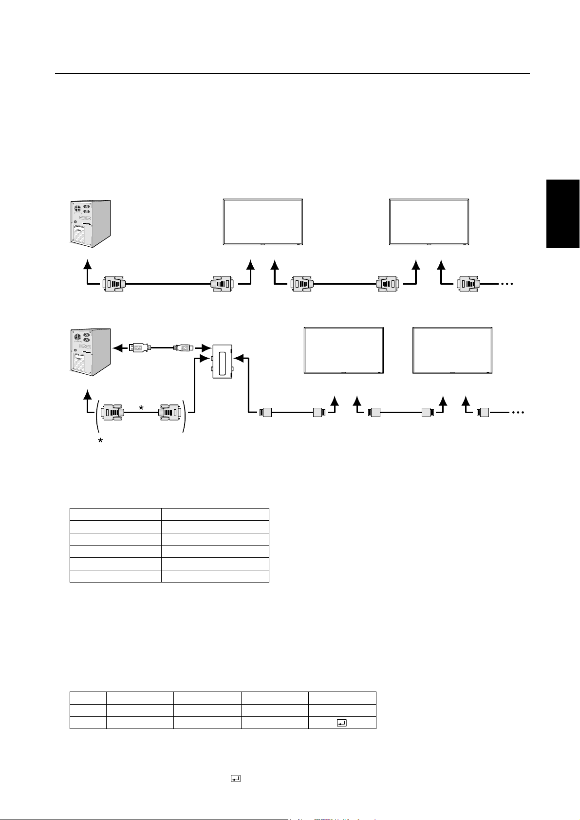
Steuern des LCD-Monitors mittels RS-232C/RS-485-Steuerung
Dieser LCD-Monitor kann über einen PC, der mit einem RS-232C- oder CAT5-Kabel an die CAT5 Tx BOX (Option) und die CAT5
Rx BOX (Option) angeschlossen ist, gesteuert werden.
Folgende Funktionen können vom Computer aus gesteuert werden:
• Ein- und Ausschalten
• Wechseln des Eingangssignals
Anschluss
Anschluss über RS-232C (Als RS-232C-Kabel muss ein Reverse-Kabel verwendet werden.)
Monitor Monitor
Deutsch
PC
RS-232C
Anschluss über CAT5 RS-485 (Bei Verwendung von CAT5-Kabeln ist der gerade Kabeltyp einzusetzen.)
Typ A Typ B
USB-Kable
PC
HINWEIS:
Falls Ihr (IBM- oder IBM-kompatibler) Computer nur über einen 25-poligen seriellen Anschluss verfügt, benötigen Sie einen
entsprechenden Adapter. Weitere Informationen erhalten Sie bei Ihrem Händler.
1) Schnittstelle
PROTOKOLL
BAUDRATE
DATENLÄNGE
PARITÄTSBIT
STOPPBIT
FLUSSSTEUERUNG
An den RS-232C
RS-232C -Kable
Bei Beschaltung von USB-COM-Port ist diese Verbindung nicht erforderlich.
-Kable RS-232C-Kable
CAT5 Tx BOX
(Option)
IN
RS-232C/RS-485 (CAT5)
9600 [bps]
8 [Bit]
KEINES
1 [Bit]
KEINE
An den RS-232C OUTAn den RS-232C IN An den RS-232C OUTAn den RS-232C IN
Monitor mit CAT5
Rx BOX (Option)
An den CAT5
OUT
CAT5 -Kable
An den CAT5
RGB5 IN
An den CAT5
OUT
An den CAT5
RGB5 IN
CAT5 -Kable
Monitor mit CAT5
Rx BOX (Option)
An den CAT5
OUT
Dieser LCD-Monitor verwendet RXD-, TXD- und GND-Leitungen für die RS-232C-Steuerung.
2) Tabelle der Steuerbefehle
Ein Befehl setzt sich aus Adresscode, Funktionscode, Datencode und Endcode zusammen. Die Länge der Befehle ist jenach
Funktion unterschiedlich.
HINWEIS:
Das nachfolgende Beispiel zeigt die grundlegenden Befehle für eine Konfi guration, die aus einem Computer und einem
Monitor besteht (Eins-zu-Eins-Anschluss). Die Befehle für die Steuerung von mehr als einem angeschlossenen Monitor
erfragen Sie bitte im Voraus bei Ihrem Händler.
Adresscode
HEX
ASCII
[Addresscode] 30h 30h (ASCII-Code, ‘0’ ‘0’) unveränderlich.
[Funktionscode] Ein Code für jede feste Steuerbewegung.
[Datencode] Ein Code für jede feste Steuerungszahl (wird nicht immer angezeigt).
[Endcode] 0Dh (ASCII-Code, ‘
30h 30h
‘0’ ‘0’
Funktionscode
Function
Function
Datencode
Data
Data
’) unveränderlich.
Endcode
0Dh
Deutsch-35
Page 82

3) Steuerungsablauf
(1) Der Befehl von einem Computer an den LCD-Monitor wird innerhalb von 600 ms gesendet.
(2) Der LCD-Monitor sendet 600 ms* nach Empfang und Ausführung eines Codes einen Rückkehrbefehl. Wenn der Befehl
nicht korrektempfangen wurde, sendet der LCD-Monitor keinen Rückkehrbefehl.
(3) Der PC prüft den Befehl und kontrolliert damit, ob der gesendete Befehl ausgeführt wurde.
(4) Dieser LCD-Monitor sendet außer dem Rückkehrcode verschiedene Codes. Wenn die RS-232C-Einheit eine Steuer-
ungssequenzvorgibt, verwerfen Sie jegliche vom PC ausgegebenen Codes.
* Unter Umständen wird das Absenden des Rückkehrbefehls verzögert (z. B. beim Ändern des Eingangssignals u. a.).
Beispiel: Einschalten des Geräts ( ‘ ’ steht für ASCII-Code).
Senden von
Befehlenvom PC aus
30 30 21 0D
‘0’ ‘0’ ‘!’ ‘ ’
Statuscode vom
LCD-Monitor
30 30 21 0D
‘0’ ‘0’ ‘!’ ‘ ’
Bedeutung
Befehl für
POWER ON
Befehl wurde empfangen
(Befehl wird zurückgesendet)
4) Operationsbefehle
Die Operationsbefehle nehmen die grundlegenden Bedienungseinstellungen des LCD-Monitor vor.
Bei einer Signaländerung ist der Monitor eventuell nicht betriebsbereit:
Operation ASCII HEX
POWER ON ! 21h
POWER OFF " 22h
INPUT RGB 1 _r1 5Fh 72h 31h
INPUT RGB 2 _r2 5Fh 72h 32h
INPUT RGB 3 _r3 5Fh 72h 33h
INPUT RGB 4 _r4 5Fh 72h 34h
INPUT RGB 5* _r5 5Fh 72h 35h
INPUT RGB 6 _r6 5Fh 72h 36h
INPUT VIDEO _v1 5Fh 76h 31h
INPUT DVD/HD _v2 5Fh 76h 32h
INPUT S-VIDEO** _v3 5Fh 76h 33h
• Der Befehl POWER OFF darf erst eine Minute nach dem
Einschalten ausgegeben werden.
• Der Befehl POWER ON darf erst eine Minute nach dem
Ausschalten ausgegeben werden.
* RGB 5 lässt sich wählen, wenn die optionale CAT5 Rx BOX
angebracht ist.
** S-VIDEO nur SEPARAT
5) Lesebefehl
Der Host-Computer sendet den Befehl ohne Datencode zum Monitor.
Nachdem der Monitor den Befehl empfangen hat, sendet er ihn mit dem Datencode des aktuellen Status an den Host-Com-
puter zurück.
Beispiel: Wenn der Host-Computer den Power-Status des Monitors abfragt, ist die Rückmeldung des Monitors „powered-on“
(eingeschaltet).
Befehl vom Computer
30 30 76 50 0D ‘0’‘0’‘v’‘P’[enter]
Befehl vom Monitor
30 30 76 50 31 0D ‘0’‘0’‘v’‘P’‘1’[enter]
Details des Befehls
Fragt den Power-Status des Monitors ab.
Monitor ist angeschaltet (powered-on).
Struktur des Lesebefehls
Netzspannung
Eingang
Bildmodus
Temperatur
im Monitor
* : RGB-5 lässt sich wählen, wenn die optionale CAT5 Rx BOX angebracht ist.
EIN
AUS (Standby) 0 76 50 30
RGB-1 (HDMI) vI r1 76 49 72 31
RGB-2 (DVI-D) vI r2 76 49 72 32
RGB-3 (D-SUB) vI r3 76 49 72 33
RGB-4 (BNC)
RGB-5* (CAT5) vI r5 76 49 72 35
RGB-6 (DISPLAY PORT)
Video vI v1 76 49 76 31
DVD/HD vI v2 76 49 76 32
S-VIDEO vI v3 76 49 76 33
HIGHBRIGHT vM
STANDARD p2 76 4D 70 32
Im Bereich der
Hauptplatine
Im Bereich des
Inverter PCB
Auflösung
1 ˚C
Auflösung
1 ˚C
Funktion Empfangene Daten Funktion Empfangene Daten
vP
vP
vI r4 76 49 72 34
vI r6 76 49 72 36
vM
tc1
tc2
ASCII HEX
1 76 50 31
p1 76 4D 70 31
(ex.) +25
(ex.) +31
74 63 31 2B 20 32 35
74 63 32 2B 20 33 31
Deutsch-36
Page 83

Merkmale und Funktionen
Farbsteuerungssysteme:
Ermöglicht die Einstellung der Farben auf dem Bildschirm und die Anpassung der Farbtreue des Monitors an eine Reihe von
Standards.
sRGB-Farbsteuerung:
Hierbei handelt es sich um einen optimierten Farbverwaltungsstandard, der einen Farbabgleich zwischen Computerbildschirmen
und anderen Peripheriegeräten ermöglicht. Der sRGB-Standard basiert auf einem kalibrierten Farbraum und sorgt für optimale
Farbdarstellung sowie Abwärtskompatibilität mit anderen gängigen Farbstandards.
OSD-Steuerungen (On-Screen Display):
Sie können das Bild schnell und einfach mit auf dem Bildschirm angezeigten Menüs einstellen.
Plug&Play:
Diese Microsoft
Installation, da der Monitor Daten zu seinen Merkmalen (beispielsweise Bildschirmgröße und unterstützte Aufl ösungen) an den
Computer senden kann und die Bildschirmdarstellung automatisch optimiert.
Intelligent Power Manager-System:
Dieses System stellt innovative Stromsparmethoden bereit, mit deren Hilfe der Monitor in einen Modus mit geringerer Leistungsaufnahme umschaltet, wenn er nicht genutzt wird. Dadurch können zwei Drittel der Stromkosten gespart sowie Emissionen und
Kosten für die Klimatisierung des Arbeitsplatzes reduziert werden.
Mehrfrequenztechnologie:
Automatische Anpassung des Monitors an die Zeilen- und Bildfrequenzen der Grafi kkarte. Dadurch wird immer die geforderte
Aufl ösung erreicht.
®
-Lösung in den Betriebssystemen Windows® 95/98/Me/2000/XP und Windows Vista® erleichtert Einrichtung und
Deutsch
FullScan-Funktion:
In den meisten Aufl ösungen können Sie den vollen Anzeigebereich nutzen, also mit einem größeren Bild arbeiten.
Fläche zur Wandmontage:
So können kompatible Montagevorrichtungen von Drittanbietern problemlos verwendet werden. MITSUBISHI ELECTRIC empfi e-
hlt die Verwendung eines Montageadapters, der dem TÜV-GS und/oder dem UL1678-Standard für Nordamerika entspricht.
Tiling, Randausgleich:
Bildet eine Einheit aus mehreren Bildschirmen und kompensiert dabei die Breite der Frontblende, um das Bild präzise darzustellen.
ZOOM:
Erweitert das Bild individuell in horizontaler und vertikaler Richtung.
Selbstdiagnose:
Bei Auftreten eines internen Fehlers wird eine Fehlerstatusmeldung angezeigt.
Automatischer Ausgleich bei langen CAT5-Kabeln:
Diese Funktion verhindert Bildqualitätsverluste (Farbverschiebung und zu schwache Signale) aufgrund längerer Kabel.
Deutsch-37
Page 84

Fehlerbehebung
Kein Bild
• Das Signalkabel muss richtig mit Grafi kkarte/Computer verbunden sein.
• Die Grafi kkarte muss richtig in den Steckplatz eingesetzt sein.
• Die Netzschalter an der Vorderseite des Monitors und am Computer müssen sich in der Position EIN befi nden.
• Überprüfen Sie, ob ein von der verwendeten Grafi kkarte unterstützter Modus ausgewählt wurde.
(Informationen zum Ändern des Grafi kmodus fi nden Sie im Handbuch zur Grafi kkarte bzw. zum System.)
• Überprüfen Sie, ob für Monitor und Grafi kkarte die empfohlenen Einstellungen vorgenommen wurden.
• Prüfen Sie, ob der Stecker des Signalkabels verbogen wurde oder ob Stifte im Stecker fehlen.
•
Ist nichts auf dem Bildschirm zu sehen, wenn das HDCP-Gerät angeschlossen ist, schalten Sie das Gerät aus und wieder an.
Netzschalter reagiert nicht
• Ziehen Sie das Netzkabel des Monitors aus der Steckdose, um den Monitor auszuschalten und zurückzusetzen.
Bildschatten
• Bei Geräten mit LCD-Technologie tritt ein Phänomen auf, das als Bildschatten bekannt ist. Bildschatten sind verbleibende
oder sogenannte „Geister“-Bilder, die vom vorhergehenden Bild sichtbar auf dem Bildschirm bleiben. Im Unterschied zu
CRT-Monitoren ist der Bildschatten auf LCD-Monitoren nicht dauerhafter Natur, aber die Anzeige von Standbildern über eine
längere Zeit sollte vermieden werden. Sie können den Bildschatten beseitigen, indem Sie den Monitor so lange ausschalten,
wie das vorherige Bild angezeigt wurde. Wurde auf dem Monitor beispielsweise eine Stunde lang ein Standbild angezeigt
und bleibt ein „Geister“-Bild sichtbar, sollte der Monitor mindestens eine Stunde ausgeschaltet werden, damit der Bildschatten verschwindet.
HINWEIS:
MITSUBISHI ELECTRIC empfi ehlt die Darstellung von bewegten Bildern und die Aktivierung eines Bildschirmschoners auf allen
Anzeigegeräten, wenn sich das Bild längere Zeit nicht verändert. Schalten Sie den Monitor aus, wenn Sie ihn nicht verwenden.
Bild ist nicht stabil, unscharf oder verschwimmt
• Das Signalkabel muss richtig mit dem Computer verbunden sein.
•
Verwenden Sie die OSD-Steuerungen zur Bildeinstellung, um das Bild scharf zu stellen, indem Sie den Optimierungswert erhöhen
oder verringern. Wird der Anzeigemodus geändert, müssen die OSD-Bildeinstellungen gegebenenfalls erneut angepasst werden.
•
Überprüfen Sie, ob für Monitor und Grafi kkarte die empfohlenen Signaltimings eingestellt wurden und ob die Geräte kompatibel sind.
•
Ist der Text verstümmelt, aktivieren Sie einen Videomodus ohne Zeilensprung (Non-Interlaced) und eine Wiederholfrequenz von 60 Hz.
Das Komponentensignal wird grünlich angezeigt
• Überprüfen Sie, ob der DVD/HD-Eingangsanschluss gewählt wurde.
Die LED am Monitor leuchtet nicht (grün oder rot)
• Der Netzschalter muss sich in der Position EIN befi nden und das Netzkabel muss angeschlossen sein.
• Stellen Sie sicher, dass sich der Monitor nicht im Stromsparmodus befi ndet (drücken Sie eine Taste oder bewegen Sie die
Maus).
Rote LED am Monitor blinkt
• Wenden Sie sich an die nächstgelegene autorisierte Serviceniederlassung von MITSUBISHI ELECTRIC.
Bild wird nicht in der richtigen Größe angezeigt
• Verwenden Sie die OSD-Steuerungen für die Bildeinstellung, um das Bild zu vergrößern bzw. verkleinern.
• Überprüfen Sie, ob ein von der verwendeten Grafi kkarte unterstützter Modus ausgewählt wurde. (Informationen zum Ändern
des Grafi kmodus fi nden Sie im Handbuch zur Grafi kkarte bzw. zum System.)
Ausgewählte Aufl ösung wird nicht richtig dargestellt
• Öffnen Sie das OSD-Menü „Information“ und überprüfen Sie, ob die richtige Aufl ösung gewählt wurde. Ist das nicht der Fall,
wählen Sie die entsprechende Option.
Deutsch-38
Page 85

Kein Ton
• Prüfen Sie, ob das Lautsprecherkabel richtig angeschlossen ist.
• Prüfen Sie, ob die Stummschaltung aktiviert wurde.
• Prüfen Sie, ob für die Lautstärke der niedrigste Wert eingestellt wurde.
Fernbedienung ist nicht möglich
• Prüfen Sie die Batterien der Fernbedienung.
• Prüfen Sie, ob die Batterien richtig eingelegt sind.
• Prüfen Sie, ob die Fernbedienung auf den Fernbedienungssensor am Monitor zeigt.
Die ZEITPLAN-/ABSCHALT-TIMER-Funktion arbeitet nicht korrekt.
• Die ZEITPLAN-Funktion wird deaktiviert, wenn der ABSCHALT-TIMER eingeschaltet wird.
• Wenn die ABSCHALT-TIMER-Funktion ak tiviert ist und die Netzspannung ausgeschaltet oder unterbrochen wird, wird der
ABSCHALT-TIMER zurückgesetzt.
Streifenartiges Rauschen
Abhängig vom spezifi schen Anzeigemuster erscheinen eventuell helle vertikale oder horizontale Streifen. Dies ist kein
Produktfehler oder –schaden.
Auf dem Bildschirm erscheint “NO SIGNAL”
Das Bild kann direkt nach dem Anschluss des HDCP-Geräts nicht visualisiert werden.
Deutsch
Deutsch-39
Page 86

Technische Daten
Specifi cations (MDT421S)
Produktspezifikationen
LCD-Modul
Kontrastverhältnis:
Betrachtungswinkel:
Frequenz
Pixeltakt
Sichtbare Bildgröße
Eingangssignal
PC-Eingang:
VIDEO-Eingang:
AUDIO-Eingang:
RS-232C:
Ausgangssignal
PC-Ausgang:
VIDEO-Ausgang:
AUDIO-Ausgang:
Lautsprecher-Ausgang:
RS-232C:
Unterstützte Auflösungen
Stromversorgung
Stromaufnahme
Betriebsumgebung
Lagerumgebung
Maße
Gewicht
Fläche zur Wandmontage
Erfüllte Normen und Richtlinien
Energiesparfunktion
Plug & Play
Zubehör
HINWEIS: Die technischen Daten können ohne vorherige Ankündigung geändert werden.
Separat:
Pixelabstand:
Auflösung:
Farbe:
Helligkeit:
Reaktionszeit:
Horizontal:
Vertikal:
Video:
Synchronisition:
Eingang:
Eingang:
Video:
Synchronisition:
Ausgang:
Ausgang:
Energiesparen:
Temperatur:
Luftfeuchtigkeit:
Temperatur:
Luftfeuchtigkeit:
Netto:
Brutto:
Netto:
Brutto:
Analoger Eingang
42" / 106,7 cm
0,485 mm
1920 x 1080 Pixel (2070000 Pixel)
Mehr als 1 Milliarde Farben (je nach verwendeter Videokarte)
700 cd/m2 (Typ.)
1100:1
9 ms (G bis G)
Oben und Unten 178°, Links und Rechts 178° @CR>10
15,625 / 15,734, 31,5 - 91,1 kHz
50,0 / 58,0 - 85,0 Hz
13,5 - 165,0 MHz
930,3 x 523,3 mm / 36,6 x 20,6 Zoll
Analog RGB Video:0,7 Vp-p
Eingangswiderstand 75 Ohm
Separate HV-Synchronisition: TTL-Level (Pos. / Neg.),
Synch.-auf-Grün, Komposit Synch (0.3Vp-p)
Eingangswiderstand: 2,2 K Ohm
BNC (R,G,B,H,V), 15 Pin Mini D-sub
Komposit:1,0 Vp-p
Eingangswiderstand 75 Ohm BNC und RCA-PIN-BUCHSE-INPUT
Y/C Y:1 Vp-p C:0,286 Vp-p Eingang
Widerstand 75 Ohm S-TERMINAL-INPUT
Komponent:1,0/0,7 Vp-p
Eingangswiderstand 75 Ohm BNC-INPUT
RCA PIN-BUCHSE L/R INPUT x 2, STEREO Mini-Buchse INPUT x 1
Mini-D-Sub, 9-polig
Analog RGB Video:0,7 Vp-p mit 75 Ohm begrenzt
Separate HV-Synchronisition: TTL-Level (Pos. / Neg.)
15 Pin Mini-D-Sub
BNC-OUTPUT x 1, Komposit 1,0 Vp-p mit 75 Ohm begrenzt
RCA PIN-JACK L/R OUTPUT x 1, 0,15 Vrms mit 47 k Ohm begrenzt
Anschlussbuchse fur externe Lautsprecher, 7 W + 7 W (8 Ohm)
Mini-D-Sub, 9-polig
640 x 480 bei 60 Hz bis 85 Hz
800 x 600 bei 50 Hz, 60 Hz bis 85 Hz
1024 x 768 bei 50 Hz, 60 Hz bis 85 Hz
1280 x 768 bei 50 Hz, 60 Hz bis 85 Hz
1360 x 768 bei 50 Hz, 60 Hz bis 85 Hz
1280 x 1024 bei 60 Hz bis 85 Hz
1600 x 1200 bei 60 Hz
1920 x 1080 bei 60 Hz* (*: Empfohlene Auflösung)
1920 x 1200 bei 60 Hz
NTSC, PAL, SECAM, 4.43NTSC, PAL60 Component: 480i, 480p, 720p, 1080i, 1080p
2,4 - 1,1 A @100 - 240 V AC, 50 / 60 Hz
232 W
3 W oder weniger (Netzschalter EIN/Hauptnetzschalter EIN/Ruhemodus)
3 W oder weniger (Netzschalter AUS/Hauptnetzschalter EIN)
Landscape: 5 - 40 °C / 41-104 °F, Portrait: 5 - 35 °C / 41 - 95 °F
20 - 80 % (Ohne Kondensation)
-20 - 60 °C / -4 - 140 °F
10 - 90% (Ohne Kondensation)/90%-3,5%x(Temp-40 °C) bezüglich über 40 °C
965,6 mm (B) x 558,6 mm (H) x 115,9 mm (T) / 38,02" (B) x 21,99" (H) x 4,56" (T)
1130 mm (B) x 709 mm (H) x 280 mm (T) / 44,49" (B) x 27,91" (H) x 11,02" (T)
23,5 kg (Näherungswert)
31 kg (Näherungswert)
12 Löcher (100 mm Abstande)
Optionale Mehrzweck-Montagevorrichtung
UL60950-1/C-UL/EN60950-1/FCC-B/DOC-B/EN55022-B
EN55024/EN61000-3-2/EN61000-3-3/C-Tick/CE/BSMI/GOST-R
VESA DPM
VESA DDC2B, DDC/CI
Benutzerhandbuch, Netzkabel, Videosignalkabel, Fernbedienung, AAA Batterie (2 x),
Klemme (2 x) (zur Verhinderung eines Herunterfallens), Klemme (3 x) (zur Sicherung der Kabel),
Klemme (2 Stück) (zur Sicherung des Netzkabels, HDMI-Kabels und Display
Port-Kabels), Schraube fur die Klemme (2 x)
Deutsch-40
Digitaler Eingang
25,0 - 165,0 MHz
TMDS
HDMI, DVI-D
DISPLAY PORT
Page 87

Pinbelegung
1) Analoger RGB-Eingang (Mini-D-SUB, 15-polig): RGB3
Pin-Nr. Bezeichnung
1 Videosignal Rot
2
3
4
5
6
7
8
9
10
11
12
13
14
15
2) Analoger RGB-Eingang (CAT5): RGB5
Videosignal Grün
Videosignal Blau
GND
DDC-GND
Rot-GND
Grün-GND
Blau-GND
+5V (DDC)
SYNC-GND
GND
DDC-SDA
H-SYNC
V-SYNC
DDC-SCL
15
Mini-D-SUB, 15-polig
5
10
1
6
11
Deutsch
Kontakt-Nr. bei RJ45
#1
#2
#3
#4
#5
#6
#7
#8
3) Digitaler RGB-Eingang (HDMI): RGB1
1
TMDS Daten 2+
2
TMDS Daten 2 Abschirmung
3
TMDS Daten 2-
4
TMDS Daten 1+
5
TMDS Daten 1 Abschirmung
6
TMDS Daten 1-
7
TMDS Daten 0+
4) Digitaler RGB-Eingang (DVI-D): RGB2
TMDS Daten2-
1
TMDS Daten2+
2
3
TMDS Daten 2 Abschirmung
4
NC
5
NC
6
DDC Takt
7
DDC Daten
8
Analoge Bildsynchronsisierung
Signal
Rot-Video+
Rot VideoGrün-Video+
Blau-Video+
Blau-VideoGrün-VideoRS-485+
RS-485-
Pinbelegung für HDMI-Anschluss:
8
TMDS Daten 0 Abschirmung
9
TMDS Daten 0-
10
TMDS Takt +
11
TMDS Takt Abschirmung
12
TMDS Takt -
13
CEC
14
Nicht verbunden (N.C. on device)
Pinbelegung für DVI-D-Anschluss:
9
TMDS Daten1-
10
TMDS Daten1+
11
TMDS Daten 1 Abschirmung
12
NC
13
NC
14
+5 V Versorgungsspannung
15
Masse (Rückleitung bei
+5 V, H-SYNC und V-SYNC)
16
Hot-Plug-Erkennung
Paar
1234 5678
15
SCL
16
SDA
17
DDC/CEC Masse
18
+5 V Versorgungsspannung
19
Hot-Plug-Erkennung
17
TMDS Daten0-
18
TMDS Daten0+
19
TMDS Daten 0 Abschirmung
20
NC
21
NC
22
TMDS Takt Abschirmung
23
TMDS Takt+
24
TMDS Takt-
CAT5
1
2
1
9
17
HDMI
DVI-D
19
18
8
16
24
Deutsch-41
Page 88

5) Digitaler RGB-Eingang (DISPLAY PORT): RGB6
Pin-Nr.
1
2
3
4
5
6
7
8
9
10
6) S-VIDEO-Eingang (MINI-DIN, 4-polig): VIDEO<S>
Bezeichnung
ML_Lane 3 (n)
GND
ML_Lane 3 (p)
ML_Lane 2 (n)
GND
ML_Lane 2 (p)
ML_Lane 1 (n)
GND
ML_Lane 1 (p)
ML_Lane 0 (n)
Pin-Nr.
11
12
13
14
15
16
17
18
19
20
Bezeichnung
GND Top
ML_Lane 0 (p)
CONFIG1
CONFIG2
AUX CH (p)
GND
AUX CH (n)
Hot-Plug-Erkennung
Rückleitung
DP_PWR
19
20
DISPLAY PORT
1
2
Pin-Nr.
1
2
3
4
7) RS-232C-Eingang/Ausgang
Pin-Nr.
1
2
3
4
5
6
7
8
9
Bezeichnung
GND
GND
Y (Luminiszenz)
C (Sättigung)
Bezeichnung
NC
RXD
TXD
NC
GND
NC
NC
NC
NC
MINI-DIN, 4-polig
Mini-D-SUB, 9-polig
1
6
5
9
Deutsch-42
Page 89

Índice
Información importante ............................................................................................................................... Español-2
Medidas de seguridad, mantenimiento y uso recomendado ...................................................................... Español-4
Contenido ..................................................................................................................................................... Español-5
Denominación de las piezas y funciones ..................................................................................................... Español-6
Botones, interruptor, e indicador ................................................................................................... Español-6
Conectores y terminales ................................................................................................................. Español-7
Mando a distancia inalámbrico ....................................................................................................... Español-8
< Funcionamiento del mando a distancia > .............................................................................. Español-9
< Manejo del mando a distancia > ............................................................................................ Español-9
Procedimiento de confi guración ................................................................................................................. Español-10
Conexión de vídeo CAT5 ................................................................................................................ Español-12
Cómo montar y conectar elementos opcionales al monitor LCD ................................................................ Español-14
Conexiones .................................................................................................................................................. Español-15
Esquema de conexiones eléctricas ................................................................................................ Español-15
Conexión de un ordenador personal .............................................................................................. Español-16
Conexión a un equipo de interfaz digital ....................................................................................... Español-17
Conexión de un reproductor de DVD con salida para componentes/salida HDMI/salida DVI ....... Español-18
Conexión a una VCR/amplifi cador estéreo .................................................................................... Español-19
Funcionamiento básico ................................................................................................................................ Español-20
Modos Encendido y Apagado ........................................................................................................ Español-20
Indicador de corriente ..................................................................................................................... Español-20
Utilización de la gestión de alimentación ....................................................................................... Español-21
Selección de una fuente de vídeo .................................................................................................. Español-21
Tamaño de la imagen ...................................................................................................................... Español-21
Modo de la imagen ......................................................................................................................... Español-21
Cambio de fuente de audio ............................................................................................................ Español-21
Modo de bloqueo de mandos ........................................................................................................ Español-21
OSD de información ....................................................................................................................... Español-22
Controles OSD (On-Screen-Display: gestor de pantalla) ............................................................................. Español-23
PICTURE (IMAGEN) ....................................................................................................................... Español-24
SCREEN (PANTALLA) .................................................................................................................... Español-26
AUDIO (SOUND) ............................................................................................................................. Español-27
PICTURE IN PICTURE (IMAGEN EN IMAGEN) ............................................................................... Español-27
CONFIGURATION 1 (CONFIGURACIÓN 1) .................................................................................... Español-28
CONFIGURATION 2 (CONFIGURACIÓN 2) .................................................................................... Español-29
ADVANCED OPTION (OPCIÓN AVANZADA) .................................................................................. Español-30
NOTA ............................................................................................................................................... Español-32
< PERSISTENCIA DE LA IMAGEN > ......................................................................................... Español-32
< Para uso prolongado de pantalla pública > ........................................................................... Español-32
< CÓMO CONFIGURAR PROGRAMA > ................................................................................... Español-32
< PIP, POP y SIDE BY SIDE > ................................................................................................... Español-33
< Información suplementaria de la función de brillo automático > ........................................... Español-33
< Función de numeración del mando a distancia > .................................................................. Español-34
Control del monitor LCD mediante control remoto RS-232C/RS-485 ......................................................... Español-35
Características ............................................................................................................................................. Español-37
Solución de problemas ................................................................................................................................ Español-38
Especifi caciones .......................................................................................................................................... Español-40
Asignación de PIN ........................................................................................................................................ Español-41
Español
Español-1
Page 90

Información importante
DECLARACIÓN DE CONFORMIDAD
Este aparato cumple el apartado 15 de las normas de la CFC. Su funcionamiento está sujeto a las siguientes condiciones. (1) Este dispositivo no puede producir interferencias dañinas y (2) acepta cualquier interferencia que reciba, incluidas
las interferencias que pueden afectar al funcionamiento del equipo.
Parte responsable en EE.UU.: Mitsubishi Digital Electronics America, Inc.
Dirección: 9351 Jeronimo Road,
Irvine, California 92618 EE. UU.
Tel.: +1 - (949) 465-6000
Type of Product: Computer Monitor
Equipment Classifi cation: Class B Peripheral
Model: MDT421S (DR854)
Por la presente certifi camos que el equipo anteriormente mencionado
se ajusta a los estándares técnicos especifi cados en las normas de la CFC.
Microsoft y Windows son marcas registradas de Microsoft Corporation. Las demás marcas comerciales o marcas registradas son propiedad de sus respectivas empresas.
HDMI, el logotipo HDMI y High-Defi nition Multimedia Interface (Interfaz Multimedia de Alta Defi nición) son marcas o
marcas registradas de HDMI Licensing LLC.
El icono DisplayPort es una marca comercial de Video Electronics Standards Association, registrada en los EE.UU y otros
países.
Declaración del Departamento Canadiense de Comunicaciones
DOC: Este aparato digital de clase B cumple todos los requisitos de las normas canadienses para el control de equipos
causantes de interferencias.
C-UL: Contiene la marca C-UL y cumple las normas de seguridad canadienses según CAN/CSA C22.2 Nº 60950-1.
Información de la CFC
1. Utilice los cables específi cos que se suministran con el monitor en color MDT421S (DR854) para no provocar interferencias
en la recepción de radio y televisión.
(1) Utilice el cable de alimentación que se incluye en la caja o uno equivalente para asegurarse de que cumple la CFC.
(2) Utilice el cable de señal de vídeo apantallado que se incluye, el mini D-SUB de 15 clavijas.
2. Este equipo se ha examinado y se garantiza que cumple los límites de los aparatos digitales de clase B, conforme al apartado 15 de las normas de la CFC. Estos límites se han concebido como medida de protección efi caz contra las interferencias
dañinas en las instalaciones domésticas. Este equipo genera, utiliza y puede irradiar energía de radiofrecuencia y, si no se
instala y utiliza de acuerdo con las instrucciones, podría generar interferencias que afectaran a la comunicación por radio.
Sin embargo, no existe garantía de que no se produzcan interferencias en una instalación concreta. Si este equipo produjera interferencias que afectaran a la recepción de radio o televisión, lo cual se puede detectar apagando y encendiendo el
equipo, el usuario puede intentar corregir las interferencias de una de las siguientes formas:
• Cambie la orientación o la posición de la antena receptora.
• Separe más el equipo y la unidad receptora.
• Conecte el equipo a la toma de corriente de un circuito distinto de aquél al que esté conectada la unidad receptora.
• Pida ayuda a su distribuidor o a un técnico de radio y televisión cualifi cado.
En caso necesario, el usuario también puede contactar con el distribuidor o el técnico para que le sugiera otras alternativas.
El siguiente folleto, publicado por la Comisión Federal para las Comunicaciones (CFC), puede ser de utilidad para el usuario: “How to Identify and Resolve Radio-TV Interference Problems.”(“Cómo identifi car y resolver problemas de interfer-
encias de radio y televisión.”) Este folleto está editado por la imprenta del Gobierno de EE.UU. (U.S. Government Printing
Offi ce, Washington, D.C., 20402, Stock No. 004-000-00345-4).
Español-2
Page 91

Información importante
ADVERTENCIA
PARA PREVENIR EL PELIGRO DE INCENDIO O DESCARGAS ELÉCTRICAS, NO EXPONGA ESTE PRODUCTO A LA LLUVIA O
LA HUMEDAD. TAMPOCO UTILICE EL ENCHUFE POLARIZADO DE ESTE PRODUCTO CON UN RECEPTÁCULO DEL CABLE
DE EXTENSIÓN U OTRAS TOMAS A MENOS QUE LAS PROLONGACIONES SE PUEDAN INSERTAR COMPLETAMENTE.
NO ABRA LA CAJA DEL MONITOR, YA QUE CONTIENE COMPONENTES DE ALTO VOLTAJE. DEJE QUE SEA EL PERSONAL
DE SERVICIO CUALIFICADO QUIEN SE ENCARGUE DE LAS TAREAS DE SERVICIO.
PELIGRO
PELIGRO
PELIGRO: PARA REDUCIR EL RIESGO DE DESCARGAS ELÉCTRICAS, ASEGÚRESE DE QUE EL CABLE DE
ALIMENTACIÓN ESTÁ DESCONECTADO DEL ENCHUFE DE PARED. PARA ASEGURARSE COMPLETAMENTE DE
QUE NO LLEGA CORRIENTE A LA UNIDAD, DESCONECTE EL CABLE DE ALIMENTACIÓN DE LA TOMA DE CA.
NO RETIRE LA CUBIERTA (O LA PARTE TRASERA). EL MONITOR NO CONTIENE PIEZAS QUE DEBA MANIPULAR
EL USUARIO. DEJE QUE SEA EL PERSONAL DE SERVICIO CUALIFICADO QUIEN SE ENCARGUE DE LAS TAREAS
DE SERVICIO.
Este símbolo advierte al usuario de que el producto puede contener sufi ciente voltaje sin aislar como para causar
descargas eléctricas. Por tanto, evite el contacto con cualquier pieza del interior del monitor.
Este símbolo advierte al usuario de que se incluye documentación importante respecto al funcionamiento y el mantenimiento de este producto. Por ello, debería leerla atentamente para evitar problemas.
Este monitor LCD utiliza una lámpara que contiene mercurio. Es posible que la eliminación del monitor LCD con la
lámpara esté regulada debido a factores ambientales. Para obtener información sobre la eliminación o reciclaje,
póngase en contacto con las autoridades locales o con Electronic Industries Alliance.
Declaración
Por la presente certifi camos que el monitor
en color MDT421S (DR854)
cumple la
Directiva 2006/95/CE:
– EN 60950-1
Directiva 2004/108/CE:
– EN 55022
– EN 61000-3-2
– EN 61000-3-3
– EN 55024
Español
PELIGRO
Declaración del fabricante
y lleva la marca
Mitsubishi Electric Corporation
2-7-3, Marunouchi,
Chiyoda-Ku
Tokyo 100-8310, Japón
Declaración del fabricante
Su producto MITSUBISHI ELECTRIC está diseñado y fabricado con materiales y componentes de alta calidad que pueden ser reciclados y/o reutilizados.
Este símbolo signifi ca que el aparato eléctrico y electrónico, las pilas, baterías y los
acumuladores, al fi nal de su ciclo de vida, se deben tirar separadamente del resto de sus
residuos domésticos.
Si hay un símbolo químico impreso debajo del símbolo mostrado arriba, este símbolo
químico signifi ca que la pila, batería o el acumulador contienen un metal pesado con cierta concen-
tración. Esto se indicará de la forma siguiente:
Hg: mercurio (0,0005%), Cd: cadmio (0,002%), Pb: plomo (0,004%)
En la Unión Europea existen sistemas de recogida específi cos para productos eléctricos y electrónicos,
pilas, baterías y acumuladores usados.
Por favor, deposite los aparatos mencionados, las pilas, baterías y acumuladores en el centro de recogida/reciclado de residuos de su lugar de residencia local cuando quiera tirarlos.
i Ayúdenos a conservar el medio ambiente!
Español-3
Page 92

Medidas de seguridad, mantenimiento y uso recomendado
PARA GARANTIZAR EL RENDIMIENTO ÓPTIMO DEL
PRODUCTO, TENGA EN CUENTA LAS SIGUIENTES
INSTRUCCIONES AL CONFIGURAR Y UTILIZAR EL
MONITOR EN COLOR LCD:
• NO RETIRE LA CUBIERTA TRASERA DEL MONITOR.
No contiene piezas que deba manipular el usuario. Si
se abren o retiran las cubiertas, existe el riesgo de sufrir
descargas eléctricas peligrosas u otros daños. Las tareas
de servicio deberá realizarlas un técnico cualifi cado.
• No vierta ningún líquido en la caja ni utilice el monitor
cerca del agua.
• No inserte objetos de ningún tipo en las ranuras de la
caja, porque podrían tocar puntos con tensión peligrosos
y ser dañinos o letales, o causar descargas eléctricas,
fuego o fallos en el equipo.
No coloque objetos pesados sobre el cable de alimentación.
•
Si éste se dañara, podrían producirse descargas o fuego.
• No coloque este producto sobre un carro, soporte o mesa
inclinado o inestable, ya que el monitor podría caerse y se
podrían producir daños graves.
• Para utilizar el monitor en una fuente de alimentación de
CA de 100-120 V en América del Norte, utilice el cable de
alimentación que se suministra con el monitor.
• Para utilizar el monitor en una fuente de alimentación de
CA de 220-240 V en Europa, utilice el cable de alimentación que se suministra con el monitor.
• En el Reino Unido, utilice un cable de alimentación homologado BS con enchufe moldeado que tenga un fusible
negro (10A) instalado para utilizarlo con este monitor. Si el
monitor se le ha suministrado sin cable de alimentación,
póngase en contacto con su proveedor.
• Para utilizar el monitor en una fuente de alimentación de
CA de 220-240 V en Australia, utilice el cable de alimentación que se suministra con el monitor.
Si el equipo se le ha suministrado sin cable de aliment-
ación, póngase en contacto con su proveedor.
• Para otros casos, utilice el cable de suministro eléctrico
que cumpla con las especifi caciones de voltaje de CA del
enchufe y estén aprobados y cumplan con los estándares
de seguridad de su país en particular.
• No coloque objetos sobre el monitor ni utilice el monitor al
aire libre.
• El interior del tubo fl uorescente situado en el monitor LCD
contiene mercurio. Respete las ordenanzas de su municipio a la hora de desechar el tubo.
• No doblegue el cable de alimentación.
• No utilice el monitor en zonas con altas temperaturas,
humedad, polvo o grasa.
• Si se rompe el monitor o el cristal, no toque el cristal
líquido y tenga precaución.
• Si se daña el monitor LCD y el cristal líquido se derrama,
no lo inhale ni ingiera.
• Coloque el monitor en un lugar debidamente ventilado
para permitir que el calor se disipe sin problemas. No bloquee las aberturas ventiladas ni coloque el monitor cerca
de un radiador u otras fuentes de calor.
No coloque nada sobre el monitor.
• En caso de emergencia, tire del conector del cable de
alimentación si debe desconectar el sistema de la tensión
de alimentación. El monitor debería estar instalado cerca
de una caja de enchufe de fácil acceso.
• Trate con cuidado el monitor al transportarlo. Guarde el
embalaje. Podría necesitarlo para futuros transportes.
• Una vez al año, limpie los orifi cios de la parte posterior
de la caja para eliminar la suciedad y garantizar así un
rendimiento óptimo.
• Si va a utilizar el ventilador de forma continuada, se recomienda limpiar los orifi cios una vez al mes como mínimo.
• Al instalar las pilas del mando a distancia;
- Alinee las pilas de acuerdo a las indicaciones (+) y (-)
que se encuentran dentro del compartimiento.
- Alinee primero la indicación (-) de la batería dentro del
compartimiento.
PELIGRO:
Si se dan algunas de estas circunstancias, desenchufe inmediatamente el monitor de la toma de corriente y contacte con
el personal de servicio cualifi cado:
• Si el cable de alimentación o el enchufe está dañado.
• Si se ha derramado líquido o han caído objetos dentro del
monitor.
• Si el monitor ha estado expuesto a la lluvia o el agua.
• Si el monitor se ha caído o se ha dañado la caja.
• Si el monitor no funciona con normalidad y ha seguido las
instrucciones de servicio.
Uso recomendado
PELIGRO:
• Para garantizar el óptimo rendimiento, deje el monitor en
marcha durante 20 minutos para que se caliente.
Descanse la vista periódicamente enfocándola hacia un objeto
•
situado a 1,5 metros como mínimo. Parpadee con frecuencia.
• Coloque el monitor en un ángulo de 90° respecto a las
ventanas u otras fuentes de luz para evitar al máximo los
brillos y refl ejos.
• Limpie la superfi cie del monitor con pantalla de cristal
líquido con un paño sin hilachas y no abrasivo. No utilice
líquidos limpiadores ni limpiacristales.
• Ajuste los controles de brillo, contraste y nitidez del monitor para mejorar la legibilidad.
• Evite visualizar patrones fi jos en el monitor durante largos
períodos de tiempo. De ese modo, evitará la persistencia
de la imagen (efectos post-imagen).
• Revise su vista con regularidad.
Ergonomía
Para conseguir las máximas ventajas ergonómicas, recomendamos que:
• Utilice los controles de tamaño y posición predefi nidos
con señales estándar.
• Utilice la confi guración de color predefi nida.
• Utilice señales no entrelazadas.
• No utilice el color azul primario en un fondo oscuro, ya
que no se ve fácilmente y, dado que el contraste es insufi -
ciente, podría fatigarle la vista.
Español-4
Page 93

Contenido
Su nueva caja de monitor MDT421S debería contener:
• Un monitor LCD
• Un cable de alimentación (3 m)
• Un cable de señal - Video (4 m)
• Un manual del usuario
• Un mando a distancia inalámbrico y pilas AAA
• Una abrazadera x 2 (Para prevenir caídas)
• Una abrazadera x 3 (Para asegurar los cables)
• Una abrazadera x 2 (Para asegurar el cable de alimentación, el cable HDMI y el cable Display Port)
• Un tornillo para la abrazadera (Para prevenir caídas) x 2
42" LCD Display Monitor
USER’S MANUAL
BEDIENERHANDBUCH
MANUAL DEL USUARIO
MANUEL UTILISATEUR
MANUALE UTENTE
GEBRUIKERSHANDLEIDING
Un manual del usuario
Cable de señal - Vídeo
(cable de D-SUB a D-SUB)
Español
Una abrazadera x 3
(Para asegurar los cables)
(Para asegurar el cable de alimentación,
Una abrazadera x 2
el cable HDMI y el cable Display Port)
* El cable de alimentación suministrado varía dependiendo del destino.
Para UE
Para América
del Norte
Cable de alimentación
* En los demás casos, utilice un cable de potencia compatible con la
corriente alterna de la salida de potencia que esté autorizado y cumpla
las normas de seguridad del país correspondiente.
Un tornillo para la
abrazadera (M4) x 2
Una abrazadera x 2
(Para prevenir caídas)
Mando a distancia
inalámbrico y pilas AAA
* Recuerde conservar la caja y el material de embalaje originales para poder transportar el monitor en el futuro.
Los componentes siguientes son opcionales.
• Altavoz externo
• Soportes
• Bisel
• CAT5 Kit
Español-5
Page 94

Denominación de las piezas y funciones
Botones, interruptor, e indicador
ON
OFF
Sensor del mando a distancia e Indicador de corriente
Recibe la señal del mando a distancia (cuando se utiliza el
mando a distancia inalámbrico). Véase también la página 9.
La luz verde se enciende cuando el monitor LCD está ENCENDIDO y la roja cuando el monitor LCD está en modo
APAGADO. Las luces verde y roja se encienden a la vez cuando el monitor LCD está en modo de AHORRO DE ENERGÍA.
Cuando PROGRAMA está activado, parpadeará entre verde
y rojo. Véase la página 21. En caso de detectar un fallo, la luz
roja parpadea.
Botón de ENCENDIDO ( )
Enciende y apaga el monitor. Véase también la página 20.
Botón MUTE
Activa y desactiva la función de silencio.
Botón INPUT
Muestra el menú de OSD (indicación en pantalla) para
conmutar la entrada de vídeo.
(Podrá cambiar entre las entradas [RGB1], [RGB2], [RGB3],
[RGB4], [RGB5]*, [RGB6], [DVD/HD], [VIDEO<S>] y [VIDEO]
con los botones de ARRIBA (
* : [RGB 5] está disponible si se monta el CAT5 Rx BOX
opcional.
Al pulsar este botón mientras se muestra el menú OSD se
puede desplazar hacia adelante por las opciones de menú.
(Consulte la página 23.)
) y ABAJO ( ).)
Botón MÁS (+)
Tiene la misma función que el botón (+) para incrementar el
ajuste del menú OSD. Aumenta el nivel de salida de audio
cuando el menú OSD está apagado.
Botón MENOS (-)
Tiene la misma función que el botón (-) para reducir el ajuste
del menú OSD. Reduce el nivel de salida de audio cuando el
menú OSD está apagado.
Botón ARRIBA ( )
Activa el menú OSD cuando no está en funcionamiento.
Tiene la misma función que el botón
área resaltada hacia arriba con el fi n de seleccionar el ajuste
en el menú OSD.
para desplazar el
Botón ABAJO ( )
Activa el menú OSD cuando no está en funcionamiento.
Tiene la misma función que el botón para desplazar el área resaltada hacia abajo con el fi n de seleccionar el ajuste en el menú OSD.
Botón EXIT
Pulse el botón EXIT para visualizar el menú OSD mientras no
se muestre.
Al pulsar este botón mientras se muestra el menú OSD se
puede desplazar hacia atrás por las opciones de menú.
(Se puede mover hacia adelante por las opciones de menú
mediante el botón INPUT.) Si pulsa este botón en el menú
principal, el menú OSD desaparece (consulte la página 23).
Sensor de brillo (frontal, trasero)
Sensor para la función de brillo automático. (Véase las páginas 25 y 33.)
Interruptor principal de encendido
Interruptor de encendido/apagado para encender y apagar el
interruptor principal de encendido.
NOTA: Modo Bloqueo de la tecla Control
Este control bloquea totalmente el acceso a todas las funciones de la tecla Control.
la tecla Control, mantenga pulsados los botones “
durante más de tres segundos.
ario, mantenga pulsados los botones “
más de tres segundos.
Para activar la función de bloqueo de
” y “ ”
Para volver al modo de usu-
” y “ ” durante
Español-6
Page 95

Conectores y terminales
(OUT)
(IN)
(OUT)
(IN)
(IN)
(IN)
Español
Ranura para CAT5 Rx BOX
El CAT5 Rx BOX (opción) se inserta en esta ranura. (Consulte
la página 12.)
NOTA:
No conecte jamás dispositivos de red a los conectores CAT5
IN y OUT. Si lo hace, se pueden afectar adversamente entre sí
provocando una ruptura.
CONTROL EXTERNO (mini D-Sub de 9 clavijas)
Conecte el conector IN al conector RS-232C OUT del ordenador o de un monitor MDT421S de conexión múltiple.
Conecte el conector OUT con el conector RS-232C IN de un
MDT421S o MDT521S de conexión múltiple.
VÍDEO IN/OUT
Conector VIDEO IN (BNC y RCA): para la entrada de señal
de vídeo compuesta. Los conectores BNC y RCA no pueden
utilizarse a la vez. (Utilice exclusivamente una entrada.)
Conector VIDEO OUT (BNC): para la salida de señal vídeo
compuesta desde el conector VIDEO IN.
Conector S-VIDEO IN (MINI DIN de 4 clavijas): para la entrada de S-Vídeo (señal separada Y/C).
RGB 4 IN / DVD/HD IN (BNC)
Para introducir señales analógicas RGB desde un ordenador
u otro equipo de RGB.
Conexión de equipos como un reproductor de DVD, un
dispositivo HDTV o un reproductor de discos láser. Véase la
página 16, 18.
Conector de entrada CA
Conecta el cable de alimentación que se suministra con el
producto.
TERMINAL DE ALTAVOZ EXTERNO
Para emitir la senal de audio hacia altavoces externos desde
el conector AUDIO 1, 2, 3 o HDMI.
AUDIO OUT
Para emitir la salida de señal de audio desde el conector AUDIO 1, 2, 3 o HDMI.
AUDIO IN 1, 2, 3
Para la entrada de señal de audio desde dispositivos externos, como ordenadores, VCR o reproductores de DVD.
RGB 1 IN (HDMI)
Para dar entrada a las señales RGB digitales desde un
ordenador, reproductor DVD, etc.
* Este conector no soporta entrada analógica.
AUDIO es soportado por HDMI.
RGB 2 IN (DVI-D)
Para introducir señales digitales RGB desde un ordenador.
* Este conector no soporta entrada analógica.
AUDIO es soportado por DVI-D.
RGB 3 IN (mini D-Sub de 15 clavijas)
Para introducir señales analógicas RGB desde un ordenador
personal u otro equipo de RGB.
RGB OUT (mini D-Sub de 15 clavijas)
Para la salida de la señal RGB 3, 4 o 5 IN.
RGB 6 IN (DISPLAY PORT)
Para introducir señales digitales RGB desde un ordenador.
Español-7
Page 96

Mando a distancia inalámbrico
Botón de ENCENDIDO
Enciende y apaga el monitor.
* Si el indicador LED de corriente del monitor no está ilumi-
nado, no funcionará ningún control.
Botón INPUT
Permite seleccionar la señal de entrada [RGB1] (HDMI),
[RGB2] (DVI-D), [RGB3] (D-SUB), [RGB4] (BNC), [RGB5]*
(CAT5), [RGB6] (DISPLAY PORT), [DVD/HD] (YPbPr),
[VIDEO<S>] y [VIDEO].
* : [RGB 5] está disponible si se monta el CAT5 Rx BOX
opcional.
Botón PICTURE MODE
Selecciona el modo de imagen: [HIGHBRIGHT], [STANDARD]
(ESTÁNDAR), [sRGB] o [CINEMA] (CINE). Véase la página 21.
HIGHBRIGHT: para imágenes en movimiento como vídeo
STANDARD (ESTÁNDAR): para imágenes (Ajuste de fábrica)
sRGB: para imágenes de texto
CINEMA (CINE): para películas
Botón DISPLAY
Hace aparecer y desaparecer la información de OSD. Véase
la página 22.
Botón SET
Tiene la misma función que el botón SET del menú OSD.
Botón de reducción MENOS
Tiene la misma función que el botón (-) para reducir el ajuste
en el menú OSD.
La pequeña pantalla que ha ajustado el modo “PIP” se mueve
hacia la izquierda.
Español-8
Botón AUTO SETUP
Para introducir el menú de confi guración automática. Véase la
página 28.
Botón AUDIO INPUT
Pulse este botón para cambiar la fuente de audio de cada
fuente de vídeo. La fuente de audio cambia en el orden de
[AUDIO1], [AUDIO2], [AUDIO3] y [HDMI]. Tenga en cuenta que
no es posible seleccionar la fuente de audio para [VIDEO<S>]
o [VIDEO]. Se puede seleccionar [HDMI] sólo cuando la fuente
de vídeo es [RGB 1].
Botón PIP (Picture In Picture: Imagen en Imagen)
Botón ON/OFF: PIP-ON/OFF. Véase la página 27, 33.
Botón INPUT: seleccione la señal de entrada “imagen en
imagen”.
Botón CHANGE: sustituye la imagen principal y la subimagen.
Nota:
Los modos “PIP” y “POP” no funcionan si el tamano de pantalla es [CUSTOM] (personalizado) o [REAL] (real).
Botón STILL
Botón ON/OFF: para encender y apagar el modo de
imagen en pausa.
Botón CAPTURE: captura la nueva imagen.
Botón SIZE
Selecciona el tamaño de la imagen: [FULL] (COMPLETA),
[NORMAL], [CUSTOM] (PERSONALIZADO), [DYNAMIC] y
[REAL]. Véase la página 21.
Botón MENU
Para activar y desactivar el menú.
Botón ARRIBA
Tiene la misma función que el botón para desplazar el área
resaltada hacia arriba con el fi n de seleccionar el ajuste en el
menú OSD.
La pequeña pantalla que ha ajustado el modo “PIP” se mueve
hacia arriba.
Botón de aumento MÁS
Tiene la misma función que el botón (+) para incrementar el
ajuste en el menú OSD.
La pequeña pantalla que ha ajustado el modo “PIP” se mueve
hacia la derecha.
Botón EXIT
Permite volver al menú anterior del menú OSD.
Botón ABAJO
Tiene la misma función que el botón para desplazar el área
resaltada hacia abajo con el fi n de seleccionar el ajuste en el
menú OSD.
La pequeña pantalla que ha ajustado el modo “PIP” se mueve
hacia abajo.
Botón MUTE
Para activar y desactivar la función de silencio.
Botón VOLUME
Aumenta o reduce la señal de salida de audio.
Page 97
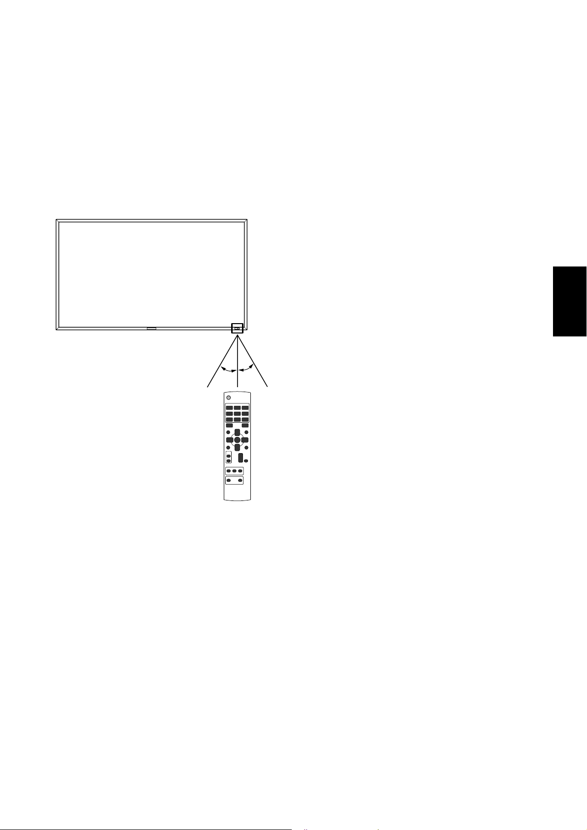
<
Funcionamiento del mando a distancia
Señale con la parte superior del mando a distancia hacia el
sensor de control remoto del monitor LCD mientras pulsa el
botón.
Utilice el mando a una distancia máxima de 7 m de la parte
frontal del sensor de control remoto del monitor LCD y dentro
de un ángulo horizontal y vertical de 30° a una distancia
máxima de 3 m.
30° 30°
>
Español
PELIGRO:
Es importante tener en cuenta que el sistema de control
remoto puede no funcionar cuando el sensor de control
remoto del monitor LCD recibe la luz directa del sol o está
sometido a una fuerte
iluminación o cuando hay algún objeto entre el mando a
distancia y el sensor del monitor.
< Manejo del mando a distancia >
* No lo exponga a golpes fuertes.
* Evite el contacto del mando a distancia con agua u otros
líquidos. Si el mando a distancia se moja, séquelo inmedi-
atamente.
* Evite exponerlo al calor y al vapor.
* No abra el mando a distancia excepto para colocar las
pilas.
Español-9
Page 98

Procedimiento de confi guración
1. Determine la ubicación de la instalación
PELIGRO:
NO INTENTE INSTALAR EL MONITOR LCD USTED MISMO
La instalación de la pantalla LCD debe realizarla un técnico
cualifi cado. Póngase en contacto con su distribuidor si desea
más información.
PELIGRO:
SE NECESITAN AL MENOS DOS PERSONAS PARA MOVER
O INSTALAR EL MONITOR LCD.
Si no se tiene en cuenta esta advertencia y el monitor LCD se
cae, podría causar lesiones.
PELIGRO:
No monte ni utilice el monitor al revés, ni encarado hacia
abajo.
PELIGRO:
No instale el monitor LCD en lugares expuestos a la luz solar
directa, ya que esto puede provocar defectos de visualización.
PELIGRO:
Este monitor LCD incluye un sensor de temperatura y un ventilador. Si el monitor LCD se calienta demasiado, el ventilador
se pone en marcha automáticamente. Si el monitor LCD se
recalienta y el ventilador está en funcionamiento, aparece el
menú “Peligro”. En caso de aparecer el menú “Peligro”, deje
de utilizar la unidad para que se enfríe. Si el monitor LCD se
utiliza en una caja o con una protección en la superfi cie, com-
pruebe la temperatura interior del monitor mediante “ESTADO
TEMPERATURA” (véase la página 31). Si la temperatura es
superior a la normal, active el “ventilador” mediante la función
PROTECTOR PANTALLA (véase la página 28).
IMPORTANTE:
Coloque la lámina protectora con la que se le suministró el
monitor LCD debajo de éste para que no se raye el panel.
• Coloque las pilas “AAA” de manera que la indicación de
los polos + y – de cada pila corresponda a la indicación +
y – del compartimento.
• No mezcle distintos tipos de pila.
• No mezcle pilas nuevas y usadas.
Ello hace que la pila dure menos o que se produzcan
fugas en ella.
• Retire inmediatamente las pilas agotadas para evitar que
el líquido de las mismas se derrame en el compartimento.
Si cae líquido, no lo toque, ya que puede dañarle la piel.
NOTA:
Si no va a utilizar el mando a distancia durante un periodo
prolongado, retire las pilas.
3. Conecte el equipo externo
(Véanse las páginas 15-19)
• Para proteger el equipo conectado, apague el interruptor
principal antes de realizar las conexiones.
• Consulte el manual del usuario del equipo.
4. Conecte el cable de alimentación que
se suministra con el producto
• La toma de corriente debe estar lo más cerca posible del
equipo y debe ser fácilmente accesible.
• Introduzca completamente los terminales de contacto en
la toma de corriente. Si la conexión no queda bien sujeta
pueden producirse ruidos.
NOTA:
Consulte el apartado “Medidas de seguridad, mantenimiento
y uso recomendado” de este manual para asegurarse de que
selecciona el cable de alimentación de CA adecuado.
2. Instalación y retirada de las pilas del
mando a distancia
El mando a distancia funciona con pilas AAA de 1,5 V.
Para colocar las pilas o cambiarlas:
Cómo instalar las pilas
1. Desbloquee la tapa y tire de ella en la dirección que indica
la fl echa.
2. Coloque las pilas siguiendo la indicación de los polos (+) y
(–) que hay en el receptáculo.
3. Vuelva a colocar la tapa.
Cómo retirar las pilas
1. Desbloquee la tapa y tire de ella en la dirección que indica
la fl echa.
2. Retire las pilas.
PELIGRO:
La utilización incorrecta de las pilas puede provocar fugas o
roturas en las mismas.
Preste especial atención a los siguientes puntos.
Español-10
Abrazadera
Utilice la abrazadera
para sujetar el cable
con firmeza.
5. Encienda todos los equipos externos
Una vez que los equipos estén conectados al ordenador,
encienda primero el ordenador.
Page 99

6. Funcionamiento del equipo externo
Visualización de la señal en el equipo externo que desee.
7. Ajuste el sonido
Realice los ajustes necesarios, si es preciso bajando o subiendo el volumen.
8. Ajuste la pantalla
(Véanse las páginas 24-34)
Realice los ajustes necesarios, si es preciso ajustar la confi guración o la posición de la pantalla.
9. Ajuste la imagen
(Véanse las páginas 24-34)
Realice los ajustes necesarios cuando sea preciso ajustar
características como el brillo o el contraste de la imagen.
Cómo instalar el soportes
1. Apague el monitor.
2. Apriete los tornillos de ambos lados del monitor.
NOTA:
Instale los soportes de modo que la parte más larga quede
dirigida hacia el frente.
Cómo retirar el soportes
1. Extienda la lámina protectora en una superfi cie, por
ejemplo en una mesa.
2. Coloque el monitor encima de la lámina protectora.
3. Retire los tornillos con un destornillador y colóquelos en
un lugar seguro para volver a utilizarlos.
12. Conexión del cable HDMI y cable
Display Port
10. Ajuste recomendado
Para reducir el riesgo de “persistencia de la imagen”, ajuste
los siguientes elementos en función de la aplicación utilizada.
“AHORRO DE ENERGÍA” (véase la página 28),“PROTECTOR
PANTALLA” (véase la página 28), “COLOR DEL BORDE” (véase
la página 28), “FECHA Y HORA” (véase la página 31), “PROGRAMA” (véase la página 31).
11. Instalación y retirada del soportes
Los soportes son preparados como opción.
Consulte el manual del usuario del soporte para obtener más
información.
Orificios para
tornillos para MDT421S
Español
Abrazadera
Utilice la abrazadera
para sujetar el cable
con firmeza.
Soportes
(La parte más larga
queda dirigida hacia
el frente.)
Español-11
Page 100
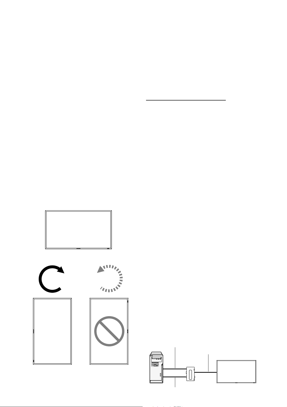
13. Cuando se instala el MDT421S en
posición vertical
Condiciones
El MDT421S puede instalarse en posición vertical bajo las
siguientes condiciones.
Precaución:
La posición vertical es efectiva solamente si se monta en la
pared o bajo el el techo.
El soporte no puede instalarse en el monitor en posición vertical.
Al situar el monitor en posición portrait, disminuirá la duración
media de la retroiluminación de la pantalla LCD.
El ambiente de operación (Temperatura) deberá estar limitado,
de acuerdo a la tabla siguiente:
Ambiente de operación:
Temperatura 5 - 35 °C / 41 - 95 °F
Humedad 20 - 80 % (sin condensación)
Ajuste la posición del producto solamente en las direcciones
sugeridas, como se muestra a continuación:
No lo coloque en posición opuesta.
Los altavoces opcionales (SP-421S) no pueden ser colocados
cuando este monitor LCD está instalado en posición vertical.
Instalación
El borde izquierdo en posición panorámica (viéndolo de frente) deberá ser el borde superior.
Panorámica
14. Para la conexión a larga distancia
mediante el CAT5 Kit
NOTA:
El CAT5 Kit es una opción diseñada para MDT421S. Para
detalles del procedimiento de montaje, consulte la guía del
usuario para el CAT5 Kit (opción).
Conexión de vídeo CAT5
La función de conexión de vídeo CAT5 es para transmitir la
señal de vídeo analógica RGB del ordenador y la señal de
control del monitor a larga distancia utilizando cables CAT5.
El ordenador puede controlar el monitor mediante el CAT5
Tx BOX opcional y el CAT5 Rx BOX que está montado en el
MDT421S.
PELIGRO:
No conecte jamás dispositivos de red (tales como un
concentrador y un ordenador para LAN) a los conectores
CAT5 IN y OUT del CAT5 Kit. Si están conectados, pueden
dañarse los dispositivos de red en sí, el CAT5 Tx BOX, el
CAT5 Rx BOX y el monitor.
1.
Instalación del controlador USB para el
control de comunicación en serie CAT5
Para conectar el ordenador y el CAT5 Tx BOX mediante la interfaz
USB, es necesario instalar el controlador USB al ordenador desde
el CD-ROM suministrado con el CAT5 Kit (opción).
(Cuando conecte el ordenador y la CAJA CAT5 Tx a través de
interfaz RS-232C, no necesitará instalar el controlador USB.)
®
Sistema operativo soportado: Windows
XP, Windows Vista®
En sentido de las
manecillas del reloj (de
izquierda a derecha)
90°
MDT421S
En sentido contrario al de
las manecillas del reloj (de
derecha a izquierda)
90°
MDT421S
Forma de instalar:
®
1) Instalación en Windows
Ejecute el archivo “PL2303-Driver_XP2K_v******.exe” en
la carpeta “Windows XP” del CD-ROM suministrado con
el CAT5 Kit (opción) e instale el controlador siguiendo las
instrucciones que se muestran en pantalla.
2) Instalación en Windows Vista
Ejecute el archivo “PL2303_Prolifi c_Vista_******.exe” en la
carpeta “Windows VISTA” del CD-ROM suministrado con
el CAT5 Kit (opción) e instale el controlador siguiendo las
instrucciones que se muestran en pantalla.
XP
®
2. Conexión de la función de conexión de
vídeo CAT5
Existen dos casos de conexión.
1) Conexión a un monitor
Ordenador
Cable USB
Cable CAT5
CAJA CAT5 Tx
(opción)
Monitor con CAT5
Rx BOX (opción)
Español-12
Cable VGA (mini D-Sub de 15 clavijas) (suministrado)
 Loading...