

Page 1
TRANSISTORIZED INVERTER
FR-S500
INSTRUCTION MANUAL (Detailed)
SIMPLE INVERTER
FR-S520E-0.1K to 3.7K (-C)
FR-S540E-0.4K to 3.7K
FR-S520SE-0.1K to 1.5K
FR-S510WE-0.1K to 0.75K
WIRING
FUNCTIONS
PROTECTIVE
FUNCTIONS
SPECIFICA TIONS
Chapter 1
Chapter 2
Chapter 3
Chapter 4
Page 2
Thank you for choosing this Mitsubishi Transistorized inverter.
WARNING
CAUTION
CAUTION
This instruction manual (detailed) provides instructions for advanced use of the FRS500 series inverters.
Incorrect handling might cause an unexpected fault. Before using the inverter, always
read this instruction manual and the instruction manual (basic) [IB-0600151E] packed
with the product carefully to use the equipment to its optimum.
This section is specifically about safety matters
Do not attempt to install, operate, maintain or inspect the inverter until you have read
through this instruction manual (basic) and appended documents carefully and can
use the equipment correctly. Do not use the inverter until you have a full knowledge
of the equipment, safety information and instructions.
In this instruction manual (detailed), the safety instruction levels are classified into
"WARNING" and "CAUTION".
Assumes that incorrect handling may cause hazardous
conditions, resulting in death or severe injury.
Assumes that incorrect handling may cause hazardous
conditions, resulting in medium or slight injury, or may cause
physical damage only.
Note that even the level may lead to a serious consequence
according to conditions. Please follow the instructions of bo th levels because they are
important to personnel safety.
1. Electric Shock Prevention
WARNING
While power is on or when the inverter is running, do not open the front cover. You
may get an electric shock.
Do not run the inverter with the front cover or wiring cover removed. Otherwise,
you may access the exposed high-voltage terminals or the charging part of the
circuitry and get an electric shock. Also, the inverter's ability to withstand
earthquakes will deteriorate.
Even if power is off, do not remove the front cover except for wiring or periodic
inspection. You may access the charged inverter circuits and get an electric shock.
Before starting wiring or inspection, check to make sure that the 3-digit LED inverter
monitor is off, wait for at least 10 minutes after the pow er s upply ha s b een switched
off, and check to make sure that there are no residual voltage using a tester or the
like.
This inverter must be earthed (grounded). Earthing (grounding) must conform to
the requirements of national and local s afety regulations and el ectrical codes. (JIS,
NEC section 250, IEC 536 class 1 and other applicable standards)
Any person who is involved in the wiring or inspection of this equipment should be
fully competent to do the work.
Always install the inverter before wiring. Otherwise, you may get an electric shock
or be injured.
Perform setting dial and key operations with dry hands to prevent an electric
shock.
Do not subject the cables to scratches, excessive stress, heavy loads or pinching.
Otherwise, you may get an electric shock.
Do not change the cooling fan while power is on. It is dangerous to change the
cooling fan while power is on.
When you have removed the front cover, do not touch the connector above the 3-
digit monitor LED display. Otherwise, you get an electrick shock.
A-1
Page 3
2. Fire Prevention
*Temperatures applicable for a short time, e.g. in transit.
Environment
Ambient
Temperature
-10°C to +50°C (non-freezing)
(-10°C to +40°C for totally enclosed structure feature)
Ambient humidity 90%RH maximum (non-condensing)
Storage
temperature
-20°C to +65°C *
Atmosphere
Indoors (free from corrosive gas, flammable gas, oil mist,
dust and dirt)
Altitude/
vibration
Max.1000m above sea level 5.9m/s
2
or less
(conforming to JIS C 60068-2-6)
CAUTION
Mount the inverter and bra ke res is to r on an i ncom bus t ibl e surf ac e. In st a lli ng th e i nve rter
and brake resistor directly on or near a combusti ble surface could lead to a fire.
If the inverter has become faulty, switch off the inverter power . A contin uous flow of
large current could cause a fire.
When using a brake resistor, make up a sequence that will turn off power when an
alarm signal is output. Otherwise, the brake resistor may excessively overheat due
to damage of the brake transistor and such, causing a fire.
Do not connect a resistor directly to the DC terminals P, N. This could cause a fire.
3. Injury Prevention
CAUTION
Apply only the voltage specified in the instruction manual to each terminal to
prevent damage, etc.
Always connect to the correct terminal to prevent damage, etc.
Always make sure that polarity is correct to prevent damage, etc.
While power is on or for some time after power-off, do not touch the inverter as it is
hot and you may get burnt.
4. Additional Instructions
Also note the following points to prevent an accidental failure, injury, electric shock,
etc.
(1) Transportation and installation
CAUTION
When carrying products, use correct lifting gear to prevent injury.
Do not stack the inverter boxes higher than the number recommended.
Ensure that installation position and material can withstand the weight of the
inverter. Install according to the information in the instruction manual.
Do not install or operate if the inverter is damaged or has parts missing.
When carrying the inverter, do not hold it by the front cover or setting dial; it may
fall off or fail.
Do not stand or rest heavy objects on the inverter.
Check the inverter mounting orientation is correct.
Prevent other conductive bodies as screws and metal fragments or other
flammable substance as oil from entering the inverter.
As the inverter is a precision ins trument, do not d rop or subject it to impact .
Use the inverter under the following environmental conditions: This could cause
the inverter damage.
A-2
Page 4
(2) Wiring
CAUTION
Do not fit capacitive equipment such as power factor correction capacitor, radio
noise filter (option FR-BIF(-H)) or surge suppressor to the output of the inverter.
The connection orientation of the output cables U, V, W to the motor will affect the
direction of rotation of the motor.
(3) Trial run
CAUTION
Check all parameters, and ensure that the machine will not be damaged by a
sudden start-up.
When the load GD
output current may v ary whe n the outp ut fre quency is i n the 20H z to 30 Hz ra nge.
If this is a problem, set the Pr.72 "PWM frequency selection" to 6kHz or higher.
(When setting the PWM to a higher frequency, check for noise or leakage current
problem and take countermeasures against it.)
(4) Operation
2
is small (at the motor GD or smaller) for 400V from 1.5K to 3.7K, the
WARNING
When you have chosen the retry function, stay away from the equipment as it will
restart suddenly after an alarm stop.
The [STOP] key is valid only when the appropriate function setting has been made.
Prepare an emergency stop switch separately.
Make sure that the start signal is off before resetting the inverter alarm. A failure to
do so may restart the motor suddenly.
The load used should be a three-phase induction motor only. Connection of any
other electrical equipment to the inverter output may damage the equipment.
Do not modify the equipment.
Do not perform parts removal which is not instructed in this manual. Doing so may
lead to fault or damage of the inverter.
A-3
Page 5
CAUTION
The electronic thermal relay function does not guarantee protection of the motor
from overheating.
Do not use a magnetic contactor on the inverter input for frequent starting/stopping
of the inverter.
Use a noise filter to reduce the effect of electromagnetic interference. Otherwise
nearby electronic equipment may be affected.
Take measures to suppress harmonics. Otherwise power supply harmonics from
the inverter may heat/damage the power capacitor and generator.
When a 400V class motor is inverter-driven, please use an insulation-enhanced
motor or measures taken to suppre ss s urge vo ltages. Surge voltages at tributable to
the wiring constants may occur at the motor terminals, deteriorating the insulation of
the motor.
When parameter clear or all clear is performed, reset the required parameters
before starting operations. Each parameter returns to the factory setting.
The inverter can be easily set for high-speed operation. Before changing its
setting, fully examine the performances of the motor and machine.
In addition to the inverter's holding function, install a holding device to ensure safety.
Before running an inverter which had been stored for a long period, always
perform inspection and test operation.
(5) Emergency stop
CAUTION
Provide a safety backup such as an emergency brake which will prevent the
machine and equipment from hazardous conditions if the inverter fails.
When the breaker on the inverter primary side trips, check for the wiring fault (short
circuit), damage to internal parts of the inverter, etc. Identify the cause of the trip,
then remove the cause and power on the breaker.
When any protective function is activated, take the appropriate corrective action,
then reset the inverter, and resume operation.
(6) Maintenance, inspection and parts replacement
CAUTION
Do not carry out a megger (insulation resistance) test on the control circuit of the
inverter.
(7) Disposing of the inverter
CAUTION
Treat as industrial waste.
(8) General instructions
Many of the diagrams an d dra wi ng s in th i s inst ruc ti o n ma nua l (detailed) show the inverter
without a cover, or p artiall y open. N ever ope rate the inverter in this m anner. Always replace
the cover and fo llow t his ins tructi on man ual (detailed) when operating the inv erter.
A-4
Page 6

CONTENTS
1. WIRING 1
1.1 Standard connection diagram and terminal specifications ..2
1.1.1 Standard connection diagram .......................................................................2
1.1.2 Explanation of main circuit terminals.............................................................3
1.2 Main circuit termina ls ............ ................ ............... ....................6
1.2.1 Terminal block layout ....................................................................................6
1.2.2 Cables, wiring length, and crimping terminals...............................................8
1.2.3 Wiring instructions.........................................................................................9
1.2.4 Selection of peripheral devices...................................................................10
1.2.5 Leakage current and installation of earth (ground) leakage circuit breaker 12
1.2.6 Power-off and magnetic contactor (MC)......................................................16
1.2.7 Regarding the installation of the power factor improving reactor................17
1.2.8 Regarding noise and the installation of a noise filter...................................18
1.2.9 Earthing (Grounding) precautions...............................................................19
1.2.10 Power supply harmonics.............................................................................20
1.2.11 Harmonic suppression guideline.................................................................21
1.2.12 Inverter-driven 400V class motor................................................................24
1.3 How to use the control circuit terminals...............................25
1.3.1 Terminal block layout ..................................................................................25
1.3.2 Wiring instructions.......................................................................................25
1.3.3 Changing the control logic............................... ...... ...... ..... ...........................26
CONTENTS
1.4 Input terminals.........................................................................28
1.4.1 Run (start) and stop (STF, STR, STOP) .....................................................28
1.4.2 Connection of frequency setting potentiometer and
output frequency meter (10, 2, 5, 4, AU).....................................................31
1.4.3 External frequency selection (REX, RH, RM, RL).......................................32
1.4.4 Indicator connection and adjustment (FM)..................................................34
1.4.5 Control circuit common terminals (SD, 5, SE).............................................36
1.4.6 Signal inputs by contactless switches.........................................................36
1.5 How to use the input signals
(assigned terminals RL, RM, RH, STR)..................................37
1.5.1 Multi-speed setting (RL, RM, RH, REX signals):
Pr. 60 to Pr. 63 setting "0, 1, 2, 8"
Remote setting (RL, RM, RH signals):
Pr. 60 to Pr. 63 setting "0, 1, 2"...................................................................37
1.5.2 Second function selection (RT signal): Pr. 60 to Pr. 63 setting "3".............37
I
Page 7

1.5.3 Current input selection "AU signal": Pr. 60 to Pr. 63 setting "4".................. 37
1.5.4 Start self-holding selection (STOP signal): Pr. 60 to Pr. 63 setting "5"....... 38
1.5.5 Output shut-off (MRS signal): Pr. 60 to Pr. 63 setting "6"........................... 38
1.5.6 External thermal relay input: Pr. 60 to Pr. 63 setting "7".............................39
1.5.7 Jog operation (JOG signal): Pr. 60 to Pr. 63 setting "9"..............................39
1.5.8 Reset signal: Pr. 60 to Pr. 63 setting "10"................................................... 40
1.5.9 PID control valid terminal: Pr. 60 to Pr. 63 setting "14"...............................41
1.5.10 PU operation/external operation switchover: Pr. 60 to Pr. 63 setting "16".. 41
1.6 Connection to the Stand-Alone Option.................................42
1.6.1 Connection of the dedicated external brake resistor (option) (FR-S520E-0.4K
to 3.7K only)................................................................................................ 42
1.6.2 Connection of the brake unit (BU type)....................................................... 43
1.6.3 Connection of the high power factor converter (FR-HC)............................. 44
1.6.4 Connection of the power regeneration common converter (FR-CV)........... 45
1.7 Handling of the RS-485 connector ................................ ........46
1.7.1 Connection of the parameter unit (FR-PU04).............................................46
1.7.2 Wiring of RS-485 communication ............................................................... 47
1.8 Design information .................................................................50
2. FUNCTIONS 51
2.1 Function (Parameter) list................. .......................................52
2.2 List of parameters classified by purpose of use..................65
2.3 Expl a n a ti on o f fu n c ti o n s (p a ra m e t e rs ) .. ............................. ..67
2.3.1 Torque boost (Pr. 0 , Pr. 46 )...................................................................... 67
2.3.2 Maximum and minimum frequency (Pr. 1 , Pr. 2 )...................................... 68
2.3.3 Base frequency, base frequency voltage (Pr.3 , Pr.19 , Pr.47 )..................69
2.3.4 Multi-speed operation (Pr. 4, Pr. 5, Pr. 6, Pr. 24 to Pr. 27, Pr. 80 to Pr. 87)70
2.3.5 Acceleration/deceleration time (Pr. 7 , Pr. 8 , Pr. 20 , Pr. 44 , Pr. 45 ) ....... 71
2.3.6 Selection and protection of a motor (Pr. 9 , Pr. 71 , H7 )............................ 73
2.3.7 DC injection brake (Pr. 10 , Pr. 11 , Pr. 12 )............................................... 75
2.3.8 Starting frequency (Pr. 13 )......................................................................... 76
2.3.9 Load pattern selection (Pr. 14 )...................................................................77
2.3.10 Jog operation (Pr.15 , Pr.16 )......................................................................78
2.3.11 RUN key rotation direction selection (Pr.17 )..............................................78
2.3.12 Stall prevention function and current limit function (Pr. 21 ) .......................79
2.3.13 Stall prevention (Pr. 22 , Pr. 23 , Pr. 28 ).................................................... 81
2.3.14 Acceleration/deceleration pattern (Pr. 29 ).................................................83
II
Page 8

2.3.15 Extended function display selec tio n (Pr. 30 )..............................................84
2.3.16 Frequency jump (Pr. 31 to Pr. 36 ).............................................................84
2.3.17 Speed display (Pr. 37 )................................................................................85
2.3.18 Biases and gains of the frequency setting voltage (current)
(Pr. 38 , Pr. 39 , C2 to C7 ).........................................................................86
2.3.19 Start-time earth (ground) fault detection selection (Pr. 40 ) ........................90
2.4 Output terminal function parameters....................................90
2.4.1 Up-to-frequency (Pr. 41 ).............................................................................90
2.4.2 Output frequency detection (Pr. 42 , Pr. 43 )...............................................91
2.5 Curren t d et e c ti o n fun c t io n p ar a me t e rs........... .. ............... .....92
2.5.1 Output current detection functions (Pr. 48 , Pr. 49 )....................................92
2.5.2 Zero current detection (Pr. 50 , Pr. 51 ).......................................................93
2.6 Display fu n c ti o n pa r a me te r s ................. ............... ............... ...94
2.6.1 Monitor display (Pr. 52 , Pr. 54 )..................................................................94
2.6.2 Setting dial function selection (Pr. 53 )........................................................95
2.6.3 Monitoring reference (Pr. 55 , Pr. 56 ).........................................................96
2.7 Restart operation parameters ................................................96
2.7.1 Restart setting (Pr. 57 , Pr. 58 , H6 )...........................................................96
2.8 Additio n a l fu n c tion parameters ... ............... ................ .. .........9 9
2.8.1 Remote setting function selection (Pr. 59 ).................................................99
2.9 Termin a l fu n c ti o n se le c t io n pa r a me ters .............................102
2.9.1 Input terminal function selection (Pr. 60 , Pr. 61 , Pr. 62 , Pr. 63 )............102
2.9.2 Output terminal function selection (Pr. 64 , Pr. 65 ) ..................................104
2.10 Operation selection function parameters ...........................105
2.10.1 Retry function (Pr. 66 , Pr. 67 , Pr. 68 , Pr. 69 )........................................105
2.10.2 PWM carrier frequency and long wiring mode (Pr. 70 , Pr. 72 )................107
2.10.3 Voltage input selection (Pr. 73 )................................................................108
2.10.4 Input filter time constant (Pr. 74 )..............................................................109
2.10.5 Reset selection/PU stop selection (Pr. 75 )...............................................109
2.10.6 Cooling fan operation selection (Pr. 76 )...................................................111
2.10.7 Parameter write disable selection (Pr. 77 )...............................................112
2.10.8 Reverse rotation prevention selection (Pr. 78 ).........................................113
2.10.9 Operation mode selection (Pr. 79 ) ...........................................................113
2.10.10PID control (Pr. 88 to Pr. 94 )...................................................................117
CONTENTS
2.11 Auxiliary pa ra meters.................. ................ ........................... 1 2 4
2.11.1 Slip compensation (Pr. 95 , Pr. 96 , Pr. 97 )..............................................124
2.11.2 Automatic torque boost selection (Pr. 98 )................................................125
III
Page 9

2.11.3 Motor primary resistance (Pr. 99 ) ............................................................ 126
2.12 Maintenance parameters......................................................126
2.12.1 Maintenance output function (H1, H2 )..................................................... 126
2.12.2 Current average value monitor signal (H3, H4, H5)..................................127
2.13 Brake parameters (FR-S520E-0.4K to 3.7K only)...............130
2.13.1 Regenerative braking operation (b1 , b2 )................................................130
2.14 Calibration parameters.........................................................131
2.14.1 Meter (frequency meter) calibration (C1 )................................................. 131
2.15 Clear param e te r s... .. ................ ............... ................ ...............134
2.15.1 Parameter clear (CLr )..............................................................................134
2.15.2 Alarm history clear (ECL )......................................................................... 134
2.16 Communicatio n p a ra me t e rs ... ............... .. ................ .............135
2.16.1 Communication settings (n1 to n7 , n11 )................................................137
2.16.2 Operation and speed command source (n8 , n9 ) ....................................152
2.16.3 Link startup mode selection (n10 )............................................................ 153
2.16.4 E2PROM write selection (n12 )................................................................. 155
2.17 Parameter un it (FR-PU04) sett in g.................. ............... ... ....156
2.17.1 PU display language selection (n13 ) .......................................................156
2.17.2 PU buzzer control (n14 )........................................................................... 156
2.17.3 PU contrast adjustment (n15 ).................................................................. 157
2.17.4 PU main display screen data selection (n16 )...........................................157
2.17.5 Disconnected PU detection /PU setti ng lock sel ec tio n (n17 )....................158
3. PROTECTIVE FUNCTIONS 159
3.1 Errors (A l a rms).. ............... ............... ................ ............... .......160
3.1.1 Error (alarm) definitions............................................................................ 161
3.1.2 To know the operating status at the occurrence of alarm
(only when FR-PU04 is used)................................................................... 169
3.1.3 Correspondence between digital and actual characters........................... 169
3.1.4 Resetting the inverter................................................................................ 169
3.2 Troubleshooting....................................................................170
3.2.1 Motor remains stopped............................................................................. 170
3.2.2 Motor rotates in opposite direction............................................................ 171
3.2.3 Speed greatly differs from the setting.......................................................171
3.2.4 Acceleration/deceleration is not smooth................................................... 171
3.2.5 Motor current is large................................................................................171
IV
Page 10

3.2.6 Speed does not increase...........................................................................171
3.2.7 Speed varies during operation ..................................................................171
3.2.8 Operation mode is not changed properly..................................................172
3.2.9 Operation panel display is not operating...................................................172
3.2.10 Parameter write cannot be performed.......................................................172
3.2.11 Motor produces annoying sound...............................................................172
4. SPECIFICATIONS 173
4.1 Specifi c a tion list. .. ................ ............... ................ ............... ...174
4.1.1 Ratings......................................................................................................174
4.1.2 Common specifications.............................................................................178
4.2 Outline drawings ...................................................................180
APPENDIX 183
APPENDIX 1 Parameter Instruction Code List .............................184
CONTENTS
V
Page 11

1. WIRING
This chapter explains the basic "wiring" for use of this product. Always
read the instructions before use.
For description of "installation", refer to the instruction manual (basic).
1.1 Standard connection diagram and terminal
specifications .....................................................
1.2 Main c ir c u it te r m i n a ls .......... ............... ............... 6
1.3 How to use the control circuit terminals.......... 25
1.4 Input terminals.................................................... 28
1.5 How to use the input signals (assigned
terminals RL, RM, RH, STR) ..............................
1.6 Connection to the Stand-Alone Option............ 42
1.7 Handling of the RS-485 connector...................... 46
1.8 Design information............................................. 50
<Abbreviations>
•PU
Operation panel and parameter unit (FR-PU04)
•Inverter
Mitsubishi transistorized inverter FR-S500 series
•FR-S500
Mitsubishi transistorized inverter FR-S500 series
•Pr.
Parameter number
2
37
Chapter 1
Chapter 2
Chapter 3
Chapter 4
1
Page 12
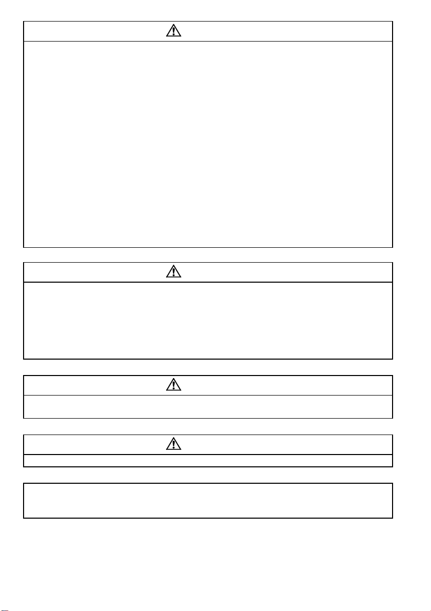
Standard connection diagram and terminal specifications
Inverter
Motor
IM
U
V
W
RUN
SE
Running
Alarm output
Operation status
output
Open
collector
Open collector
outputs
A
B
C
Frequency setting
potentiometer
1/2W1kΩ
Frequency setting signals (Analog)
10
2
2
3
1
4 to 20mADC(+)
4
0 to 5VDC
0 to 10VDC
5
Current input(-)
(+5V)
(Common)
(4 to 20mADC)
Selected
output
common
Low speed
RL
NFB MC
Power factor improving
DC reactor
(FR-BEL: Option)
Jumper:
Remove this
jumper when FR-BEL
is connected.
P1
SINK
SOURCE
Multi-speed
selection
Take care not to short
terminals PC-SD.
RS-485
Connector
Three-phase AC
power supply
Control circuit terminalMain circuit terminal
When using the current input as
the frequency setting signal, set
"4" in any of Pr. 60 to Pr. 63 (input
terminal function selection), assign
AU (current input selection) to any
of terminals RH, RM, RL and STR
and turn on the AU signal.
Control input
signals
(No voltage
input allowed)
STF
STR
RM
Forward rotation start
Reverse rotation start
Middle speed
High speed
RH
*3
FM
SD
(+)
Calibration
resistor
(-)
Earth (Ground)
R
Brake resister
Earth
(Ground)
External transistor common
24VDC power supply
Contact input common (source)
SD
PC
Contact input common
Indicator
1mA full-scale
Analog meter
(Digital indicator)
*6
*4
*6
*6
*6
*7
*7
*7
*7
*1
*2
*5
PR
R/L1
S/L2
T/L3
P/+
N/-
1.1 Standard connection diagram and terminal specifications
1.1.1 Standard connection diagram
Three-phase 200V power input
Three-phase 400V power input
REMARKS
*1. The N/- terminal is not provided for the FR-S520E-0.1K to 0.75K.
*2. The PR terminal is provided for the FR-S520E-0.4K to 3.7K.
*3. Not needed when the setting dial is used for calibration.
Used when calibration must be made near the frequency meter for such a reason as a remote frequency meter.
However, the frequency meter needle may not deflect to full-scale if the calibration resistor is connected.
In this case, use this resistor and setting dial together.
*4. You can switch the position of sink and so urce logic. Refer to page 26.
*5. When the setting potentiometer is used frequently, use a 2W1kΩ potentiometer.
*6. The terminal functions change with input terminal function selection (Pr . 60 to Pr . 63). (Refe r to page 102.)
(RES, RL, RM, R H, R T, AU, STOP, MRS, OH, REX, JO G, X14, X16, (STR) si gna l s elec tion )
*7. The terminal function changes according to the setting of output terminal function selection (Pr. 64, Pr. 65).
(Refer to page 104.) (RUN, SU, OL, FU, R Y, Y12, Y13, FDN, FUP, RL, Y93, Y95, LF, ABC signal selectio n)
2
Page 13
Standard connection diagram and terminal specifications
1
WIRING
CAUTION
To prevent a mal function d ue to nois e, keep the signa l cable s mor e than 10 cm away
from the power cables.
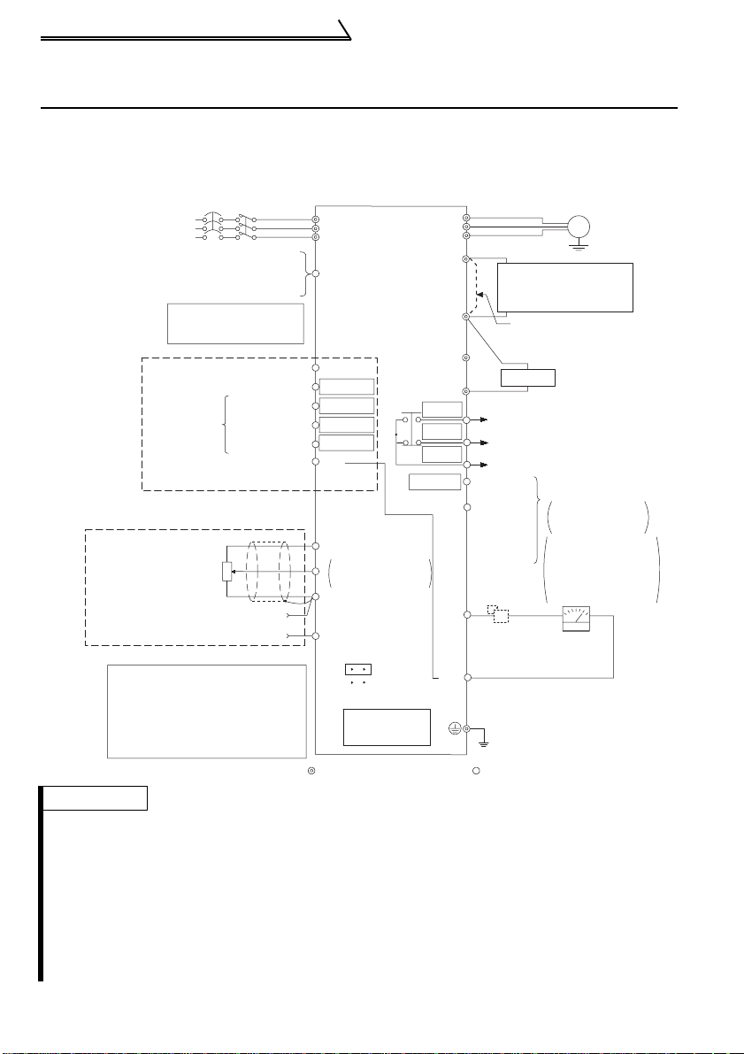
Single-phase 200V power input
Single-phase 100V power input
Power
supply
MC
R/L1
S/L
U
2
V
W
Motor
IM
Earth (Ground)
NFB
REMARKS
•To ensure safety, connect the power input to the inverter via a magnetic contactor and earth leakage
circuit breaker or no-fuse breaker, and use the magnetic contactor to switch power on-off.
•The output is three-phase 200V.
1.1.2 Explanation of main circuit terminals
(1) Main circu it
Terminal
Symbol
R/L1, S/L2,
T/L3 (*1)
U, V, W Inverter output
P/+, PR (*2)
P/+, N/−
P/+, P1
*1. When using single-phase power in put , te rm inals are R/L1 and S/L2.
*2. The PR terminal is provided for the FR-S520E-0.4K to 3.7K.
Terminal Name Description
AC power input
Brake resistor
connection
Brake unit
connection
Power factor
improving DC
reactor
connection
Earth (ground)
Connect to the com m erc i al pow er supply.
Connect a three-ph ase squirrel-cage motor.
Connect the optional brake resistor (MRS/MYS typ e, FR ABR) (The brake resi st or can be connected to the FRS520E-0.4K to 3.7K only.)
Connect the brake un it (BU), power regeneration
common converter (FR-CV) or high power factor
converter (FR-HC) . (The N/- terminal is not provided for
the FR-S520E-0.1K to 0.75 K. )
Remove the jumper across terminals P - P1 and connect
the option al power factor i m proving DC reac t or (FRBEL(-H)).
(The single-phase 10 0V power input model cannot be
connected.)
For earthing (groun di ng) th e i nve rt er chassis. Must be
earthed (grounded).
3
Page 14

Standard connection diagram and terminal specifications
(2) Control circuit
Symbol Terminal Name Definition
Turn on the STF signal to
start forward rota t i on and
turn it off to stop.
Turn on the STR signal to
start rev erse rotat i on and
turn it off to stop.
Turn on the RH, RM and RL signals in
appropriate combinations to select
multiple speeds.
The priorities of the spee d com m ands
are in order of jog, multi-speed setting
(RH, RM, RL, REX) and AU.
Common to the contact input terminals (STF, STR, RH, RM,
RL) and terminal FM. (*6)
When connecting the transistor output (open collector output),
such as a programmable controller (PLC), connect the positive
external power supply for transistor output to this terminal to
prevent a malfunction caused by undesirable currents.
This terminal can be used as a 24VDC, 0.1A power output
across terminals PC-SD.
When source logic has been selected, this terminal serves
as a contact input common.
5VDC, Permissible l oa d current 10mA.
Inputting 0 to 5VDC (or 0 to 10V) provides the maximum output
frequency at 5 V (10 V) and makes input and ou tput p ropor tion al.
Switch between 5V and 10V using Pr. 73 "0-5V , 0-10V selection".
Input resistance 10kΩ. Maximum permissible input voltage 20V
Input 4 to 20mADC. It is factory set at 0Hz for 4mA and at
60Hz for 20mA.
Maximum permiss ib le in put current 30mA. Input resistanc e
approximately 250Ω.
Turn ON signal AU for current inpu t .
Turning the AU signal on makes voltage input invalid. Use any of
Pr. 60 to Pr. 63 (input terminal function selection) to set the AU
signal.
Frequency setting signal (terminal 2, 4) common terminal.
(*6)
Input signals
STF
STR
RH
Contact input
RM
RL
SD
(*1)
PC
(*1)
10
Frequency setting
5
Forward rotation
start
Reverse rotation
start
Multi-speed
selection
Contact input
common (sink)
External
transistor
common, 24VDC
power supply,
contact input
common (source)
Frequency setting
power supply
Frequency setting
2
(voltage signal)
Frequency setting
4
(current signal)
Frequency setting
input common
When the STF and STR
signals are turned on
simultaneously, the stop
command is given.
The terminal
functions change
with input terminal
function selection
(Pr. 64, Pr.65).
(*3)
4
Page 15

Standard connection diagram and terminal specifications
1
WIRING
Symbol Terminal Name Definition
Changeover contact output indicates
A
BCAlarm output
Inverter
RUN
running
Open collector
Open collect or
SE
Output signals
common
FM For meter
Indicator
that the inverter protective function has
activate d and the output stopped.
230VAC 0.3A, 30VDC 0.3A. Alarm:
discontinuity across B-C (continuity
across A-C), Normal: continuity across
B-C (discontinuity ac ro ss A- C ) .(*5)
Switched low when the inverter output
frequency is equal to or higher than the
starting frequency (f actory set to 0.5Hz
variable). Switched high during stop or
DC injection brake ope ra tion. (*2)
Permissible load 24VDC 0. 1A (a
voltage drop is 3.4V maximum when
the signal is on)
Common terminal fo r inv er te r r unn in g t er m in al RU N .
The output signal across terminals FM-SD is factory set to about
1mA at 60Hz and is proportional to the corresponding output
frequency. Since output voltage is pulse shape, a digital meter
can be connected.
Frequency permissi ble load current 1mA
Pulse specification 1440 pulses/s at 60Hz
The function of the
terminals changes
according to the
output terminal
function selection
(Pr. 64, Pr.65).
(*4)
(*6)
Using the parameter unit connection cable (FR-CB201 to
205), the parameter unit (F R-PU04) can be connected.
Communication op er at io n can be performed using RS- 485.
For details of RS-485 comm unication, refer to page 47.
——
RS-485
connector
Communication
*1. Do not co nnect terminals SD and PC eac h ot her or to the earth (ground).
For sink logic (factory setting), terminal SD acts as the com m on terminal of contact in pu t.
For source log ic, terminal PC acts as the commo n terminal of contact input. (Re fer to
page 26 for switching meth od.)
*2. Low ind icates that the open collector outpu t transistor is on (conducts). High in dicates
that the transistor is off (does not conduct).
*3. RL, RM, RH, RT, AU, STOP, MRS, OH, REX, JOG, RES, X14, X16, (STR) signal
selection (Refer to page 10 2. )
*4. RUN, SU, OL, FU, RY, Y12, Y 13, FDN, FUP, RL , Y93, Y95, LF, ABC signal selec tion
(Refer to page 104.)
*5. To be compliant with the European Directive (Low Voltage Directive), the operating
capacity of relay outputs (A, B, C) s hould be 30VDC 0.3A.
*6. Terminals SD, SE and 5 are isolated from each other. Do not earth (gro und) .
5
Page 16
Main circuit terminals
r
P1
Motor
Jumper
U V W
IM
Power supply
R/L1 S/L2
P/+
PR
T/L3
1.2 Main circuit terminals
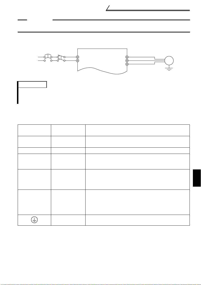
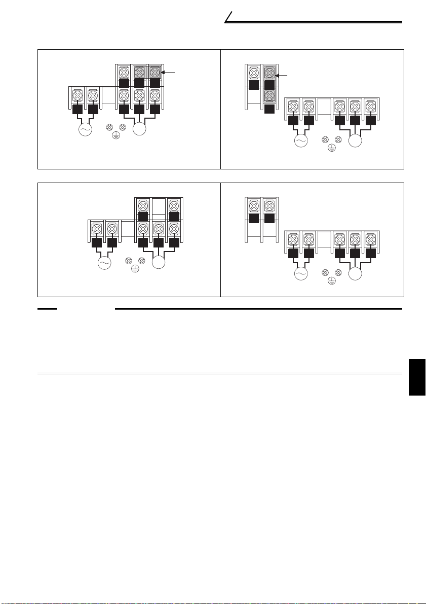
1.2.1 Terminal block layout
1)Three-phase 200V power input
• FR-S520E-0.1K, 0.2K (-C) • FR-S520E-1.5K, 2.2K, 3.7K (-C)
Jumpe
P/+
P1
R/L1 S/L2 T/L3
Power supply
U V W
IM
Motor
• FR-S520E-0.4K, 0.75K (-C)
2)Three-phase 400V power input
• FR-S540E-0.4K, 0.75K, 1.5K, 2.2K, 3.7K (-C)
N/-
PR
P/+
P1
Jumper
R/L1 S/L2 T/L3
Power supply
U V W
IM
Motor
N/-
Jumper
P/+
P1
R/L1 S/L2 T/L3
Power supply
U V W
IM
Motor
6
Page 17
1
WIRING
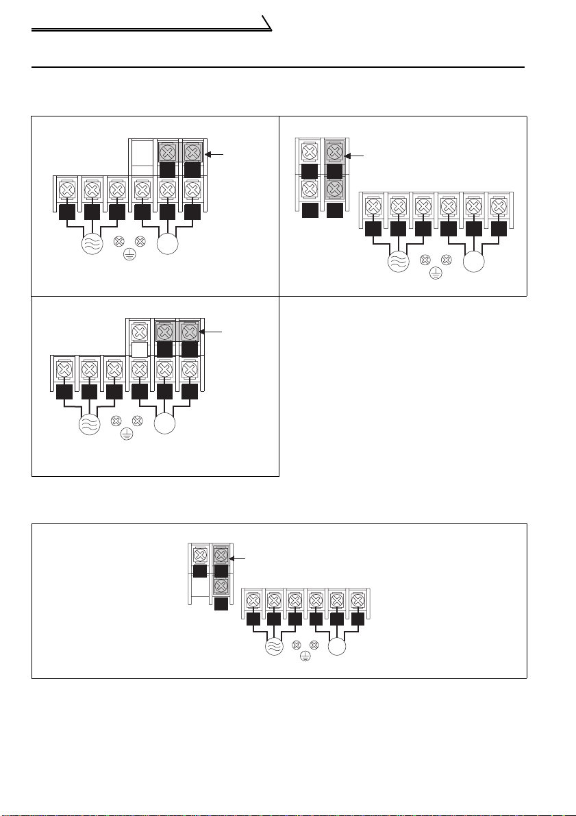
3)Single-phase 200V power input
r
• FR-S520SE-0.1K, 0.2K, 0.4K, 0.75K • FR-S520SE-1.5K
N/-
P1
P/+
N/-
Jumpe
Jumper
P/+
Main circuit terminals
R/L1 S/L2
Power supply
U V W
IM
Motor
P1
R/L1 S/L2
Power supply
U V W
IM
Motor
4)Single-phase 100V power input
• FR-S510WE-0.1K, 0.2K, 0.4K • FR-S510WE-0.75K
R/L1 S/L2
Power supply
P/+N/-
U V W
IM
Motor
N/-
P/+
R/L1 S/L2
Power supply
U V W
IM
Motor
CAUTION
•Make sure the power cables are connected to the R/L1, S/L2, T/L3 of the inverter.
Never connect the power cable to the U, V, W of the inverter. (Phase need not be
matched)
•Connect the motor to U, V, W. At this time, turning on the forward rotation switch
(signal) rotates the motor in the counterclockwise direction when viewed from the
motor shaft.
7
Page 18
Main circuit terminals
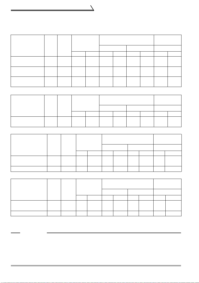
1.2.2 Cables, wiring length, and crimping terminals
The following table indicates a selection example for the wiring length of 20m.
1) Three-phase 200V power input
U, V, W
PVC Insulation
Cable
2
mm
R, S, T
U, V, W
PVC Insulation
Cable
2
mm
PVC Insulation
Cable
2
mm
PVC Insulation
Cable
2
mm
Ter-
Applied Inverter
FR-S520E-0.1K
to 0.75K (-C)
FR-S520E-
1.5K, 2.2K (-C)
FR-S520E-3.7K
(-C)
Tight-
minal
ening
Screw
Torque
size
N
M3.5 1.2 2-3.5 2-3.5 2 2 14 14 2.5 2.5
M4 1.5 2-4 2-4 2 2 14 14 2.5 2.5
M4 1.5 5.5-4 5.5-4 3.5 3.5 12 12 4 2.5
⋅
m
R, S, T U, V, W
Crimping
Terminal
R, S, T
mm
Cable
2
U, V, W
AWG
R, S, T
2) Three-phase 400V power input
Ter-
Applied Inverter
FR-S540E-0.4K
to 3.7K
Tight-
minal
ening
Screw
Torque
size
N
M4 1.5 2-4 2-4 2 2 14 14 2.5 2.5
Crimping
Terminal
⋅
m
R, S, T U, V, W R, S, T U, V, W R, S, T U, V, W R, S, T U, V, W
mm
2
Cable
AWG
3) Single-phase 200V power input
Applied Inverter
FR-S520SE-0.1K
to 0.75K
FR-S520SE-
1.5K
Termi-
Screw
Tight-
nal
ening
Torque
size
M3.5 1.2 2-3.5 2-3.5 2 2 14 14 2.5 2.5
N
M4 1.5 2-4 2-4 2 2 14 14 2.5 2.5
⋅
m
Crimping
Terminal
U, V, W U, V, W U, V, W U, V, W
mm
2
Cable
AWG
4) Single-phase 100V power input
Applied Inverter
FR-S510WE-
0.1K
to 0.4K
FR-S510WE-0.75K
Termi-
Screw
Tight-
nal
ening
Torque
size
M3.5 1.2 2-3.5 2-3.5 2 2 14 14 2.5 2.5
N
M4 1.5 5.5-4 2-4 3.5 2 12 14 4 2.5
Crimping
Terminal
⋅
m
R, S U, V, W R, S U, V, W R, S U, V, W R, S U, V, W
mm
2
Cable
AWG
Wiring length
100m maximum. (50m maximum for the FR-S540E-0.4K.)
CAUTION
•When the wiring length of the 0.1K and 0.2K of the three-phase 200V, singlephase 200V, and single-phase 100V class and 0.4K and 0.75K of the threephase 400V class is 30m or more, set the carrier frequency to 1kHz.
•When automatic torque boost is selected in Pr. 98 "automatic torque boost
selection (motor capacity)", the wiring length should be 30m maximum. (Refer
to page 125.)
8
Page 19

Main circuit terminals
1
WIRING
1.2.3 Wiri ng instructions
1) Use insulation-sleeved crimping terminals for the power supply and motor cables.
2) Application of power to the output terminals (U, V, W) of the inverter will damage the
inverter. Never perform such wiring.
3) After wiring, wire offcuts must not be left in the inverter.
Wire offcuts can cause an alarm, failure or malfunction. Always keep the inverter
clean.
When drilling a control box etc., take care not to let wire offcuts enter the inverter.
4) Use cables of the recommended size to make a voltage drop 2% maximum.
If the wiring distance is long between the inverter and motor, a main circuit cable
voltage drop will cause the motor torque to decrease especially at the output of a
low frequency.
5) For long distance wiring, the high response current limit function may be reduced or
the devices connected to the secondary side may malfunction or become faulty
under the influence of a charging current due to the stray capacity of wiring.
Therefore, note the maximum overall wiring length.
6) Electromagnetic wave interference
The input/output (main circuit) of the inverter includes high frequency components,
which may interfere with the communication devices (such as AM radios) used near
the inverter. In this case, install a FR-BIF(-H) optional radio noise filter (for use on
the input side only) or FR-BSF01 or FR-BLF line noise filter to minimize
interference.
7) Do not install a power capacitor, surge suppressor or radio noise filter (FR-BIF(-H)
option) on the output side of the inverter.
This will cause the inverter to trip or the capacitor and surge suppressor to be
damaged. If any of the above devices are connected, remove them. (When using
the FR-BIF(-H) radio noise filter with a single-phase power supply, connect it to the
input side of the inverter after isolating the T phase securely.)
8) Before starting wiring or other work after the inverter is operated, wait for at least 10
minutes after the power supply has been switched off, and check that there are no
residual voltage using a tester or the like. The capacitor is charged with high
voltage for some time after power off and it is dangerous.
9
Page 20

Main circuit terminals
1.2.4 Selection of peripheral devices
Check the capacity of the motor applicable to the inverter you purchased. Appropriate
peripheral devices must be selected according to the capacity.
Refer to the following list and prepare appropriate peripheral devices:
1) Three-phase 200V power input
No-fuse Breaker
Motor
Output
(kW)
Applied Inverter
Type
(NFB *1, 4) or
Earth Leakage
Circuit Breaker
(ELB) (Refer to
page 12) (*2, 4)
0.1 FR-S520E-0.1K(-C) 30AF/5A S-N10
0.2 FR-S520E-0.2K(-C)
0.4 FR-S520E-0.4K(-C)
0.75 FR-S520E-0.75K(-C)
30AF/5A S-N10
30AF/5A S-N10 FR-BAL-0.4K FR-BEL-0.4K
30AF/10A S-N10 FR-BAL-0.75K FR-BEL-0.75K
1.5 FR-S520E-1.5K(-C) 30AF/15A S-N10 FR- BAL- 1.5K FR-BEL-1.5K
2.2 FR-S520E-2.2K(-C)
3.7 FR-S520E-3.7K(-C)
30AF/20A S-N10 FR- BAL- 2.2K FR-BEL-2.2K
30AF/30A
2) Three-phase 400V power input
No-fuse Breaker
Motor
Output
(kW)
Applied Inverter
Type
(NFB *1, 4) or
Earth Leakage
Circuit Breaker
(ELB) (Refer to
page 12) (*2, 4)
0.4
0.75
1.5
2.2
3.7
FR-S540E-0.4K
FR-S540E-0.75K
FR-S540E-1.5K
FR-S540E-2.2K
FR-S540E-3.7K
30AF/5A S-N10
30AF/5A S-N10
30AF/10A S-N10
30AF/15A S-N10
30AF/20A
Magnetic
Contactor
(MC)
(Refer to
page 16 )
S-N20,
S-N21
Magnetic
Contactor
(MC)
(Refer to
page 16)
S-N20,
S-N21
Power Factor
Improving AC
Reactor
(Refer to page
17)
FR-BAL-0.4K
(*3)
FR-BAL-0.4K
(*3)
FR-BAL-3.7K FR-BEL-3.7K
Power Factor
Improving AC
Reactor
(Refer to page
17)
FR-BAL-
H0.4K
FR-BAL-
H0.75K
FR-BAL-
H1.5K
FR-BAL-
H2.2K
FR-BAL-
H3.7K
Power Factor
Improving DC
Reactor
(Refer to page
17)
FR-BEL-0.4K
(*3)
FR-BEL-0.4K
(*3)
Power Factor
Improving DC
Reactor
(Refer to page
17)
FR-BEL-
H0.4K
FR-BEL-
H0.75K
FR-BEL-
H1.5K
FR-BEL-
H2.2K
FR-BEL-
H3.7K
10
Page 21
1
WIRING
3) Single-phase 200V power input
No-fuse Breaker
Motor
Output
(kW ))
Applied Inverter
Type
(NFB *1, 4) or
Earth Leakage
Circuit Breaker
(ELB) (Refer to
page 12) (*2, 4)
0.1
FR-S520SE-0.1K 30AF/5A S-N10 FR-BAL-0.4K FR-BEL-0.4K
0.2
FR-S520SE-0.2K
0.4
FR-S520SE-0.4K
0.75
FR-S520SE-0.75K
1.5
FR-S520SE-1.5K
30AF/10A S-N10 FR- BAL- 0.4 K FR-BEL-0.4K
30AF/10A
30AF/15A
30AF/20A
4) Single-phase 100V power input
No-fuse Breaker
Motor
Output
(kW )
Applied Inverter
Type
(NFB *1, 4) or
Earth Leakage
Circuit Breaker
(ELB) (Refer to
page 12) (*2, 4)
0.1
FR-S510WE -0.1K
0.2
FR-S510WE -0.2K
0.4
FR-S510WE -0.4K
0.75
FR-S510WE-0.75K
30AF/10A S-N10 FR-BAL-0.75K
30AF/15A S-N10 FR-BAL-1.5K
30AF/20A
30AF/30A
Magnetic
Contactor
(MC)
(Refer to
page 16)
S-N20,
S-N21
S-N20,
S-N21
S-N20,
S-N21
Magnetic
Contactor
(MC)
(Refer to
page 16)
S-N20,
S-N21
S-N20,
S-N21
Main circuit terminals
Power Factor
Improving AC
Reactor
(Refer to page
17) (*3)
FR-BAL-0.75K FR-BEL-0.75K
FR-BAL-1.5K FR-BEL-1.5K
FR-BAL-2.2K FR-BEL-2.2K
Power Factor
Improving AC
Reactor
(Refer to page
17) (*3)
FR-BAL-2.2K
FR-BAL-3.7K
Power Factor
Improving DC
Reactor
(Refer to page
17) (*3)
Power Factor
Improving DC
Reactor
(Refer to page
17) (*5)
*1. •Select the NFB according to the inverter power
supply capacity.
•Install one NFB per inverter.
NFB
NFB INV
INV
IM
IM
*2. For installations in the United States or Canada, the circuit breaker must be inverse
time or instantaneous trip type.
*3. The power factor may be slightly lower.
*4. When the breaker on the inverter primary side trips, check for the wiring fault (short
circuit), damage to internal parts of the inverter, etc. Identify the cause of the trip,
then remove the cause and power on the breaker.
*5. The sing le-pha se 100V po wer in put model do es not al low the power fact or improv ing
DC reactor to be fitted.
11
Page 22

Main circuit terminals
1.2.5 Leakage current and installation of earth (ground) leakage circuit breaker
Due to static capacitances existing in the inverter I/O wiring and motor, leakage
currents flow through them. Since their values depend on the static capacitances,
carrier frequency, etc., take the following countermeasures.
(1) To-earth (ground) leakage currents
Leakage currents may flow not only into the inverter's own line but also into the
other line through the earth (ground) cable, etc.
These leakage currents may operate earth (ground) leakage circuit breakers and
earth (ground) leakage relays unnecessarily.
Countermeasures
• If the carrier frequency setting is high, decrease the carrier frequency (Pr. 72) of the
inverter.
Note that motor noise increases. Selection of Soft-PWM control (Pr. 70) will make it
unoffending. (Factory setting)
• By using earth leakage circuit breakers designed for harmonic and surge
suppression in the inverter's own line and other line, operation can be performed
with the carrier frequency kept high (with low noise).
12
Page 23
Main circuit terminals
1
WIRING
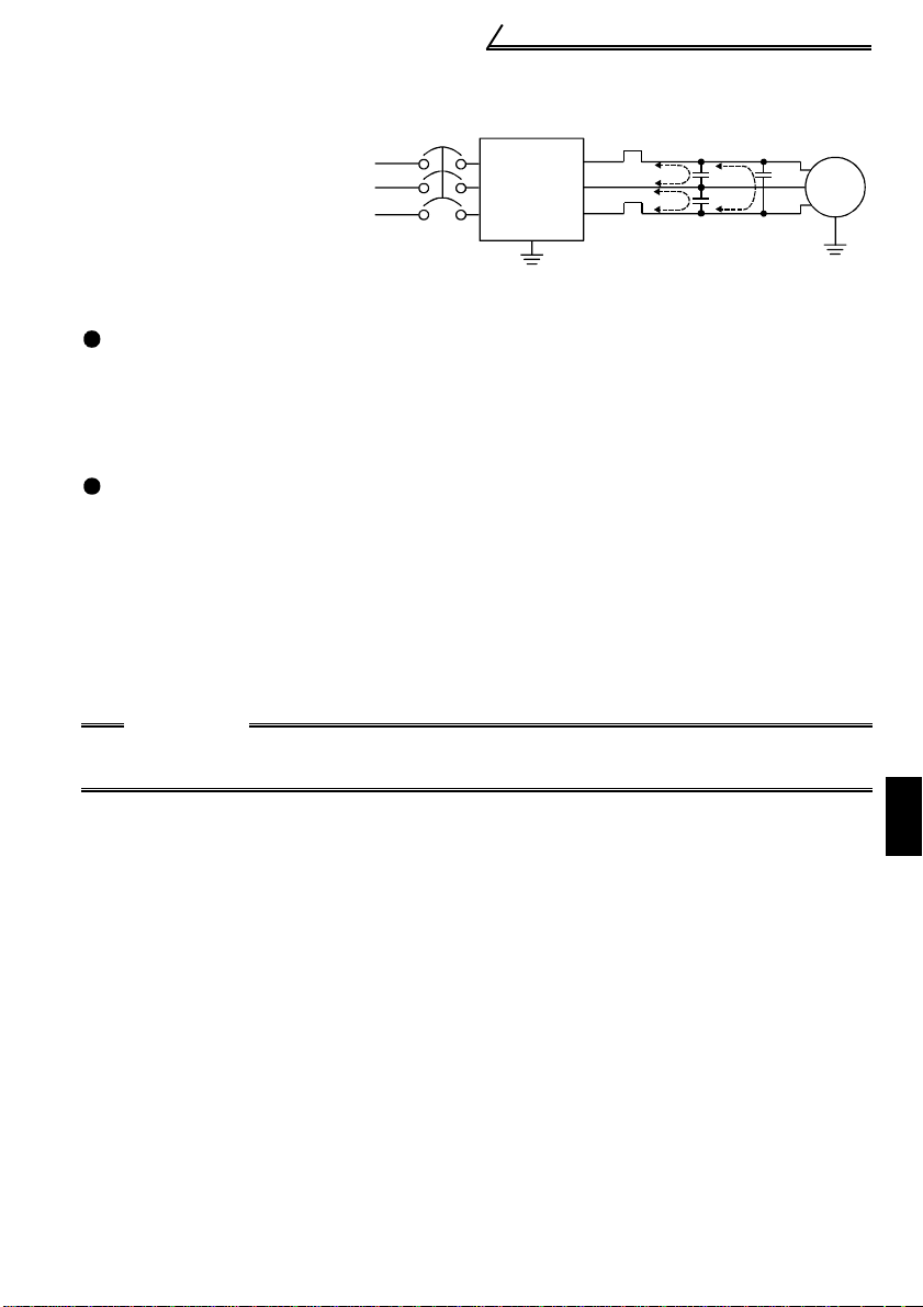
(2) Line-to-line leakage currents
Harmonics of
leakage currents
flowing in static
capacities between
Power
supply
the inverter output
cables may operate
the external thermal
relay unnecessarily.
Countermeasures
• Use the electronic thermal relay function of the inverter.
• Decrease the carrier frequency. Note that motor noise increases. Selection of
Soft-PWM (Pr. 70) makes it unoffending.
To ensure that the motor is protected against line-to-line leakage currents, it is
recommended to use a temperature sensor to directly detect motor temperature.
Installation and selection of no-fuse breaker
Install a no-fuse breaker (NFB) on the power receiving side to protect the wiring of
the inverter primary side. Select the NFB according to the power supply side power
factor (which depends on the power supply voltage, output frequency and load).
Especially for a completely electromagnetic NFB, one of a slightly large capacity
must be selected since its operation characteristic varies with harmonic currents.
(Check it in the data of the corresponding breaker.) As an earth (ground) leakage
breaker, use the Mitsubishi earth (ground) leakage breaker designed for harmonics
and surge suppression. (Refer to page 8 for the recommended models.)
NFB
Inverter
Line-to-Line Leakage Current Path
Thermal relay
Line static
capacitances
Motor
IM
CAUTION
•Select the NFB according to the inverter power supply capacity.
•Install one NFB per inverter.
13
Page 24
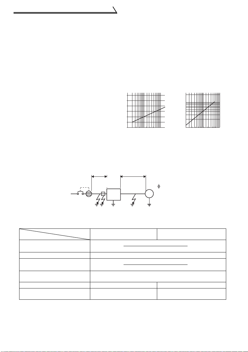
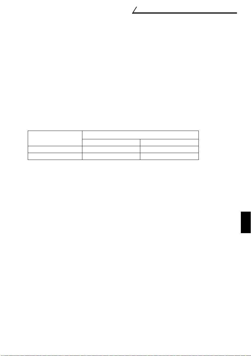
Main circuit terminals
Motor capacity (kW)
Example of leakage
current per 1km in cable
path during commercial
power supply operation
when the CV cable is
routed in metal conduit
Leakage current (mA)
Leakage current (mA)
Cable size (mm)
2
Leakage current
example of three-phase
induction motor
during commercial
power supply
operation
(200V 60Hz)
(200V 60Hz)
0
20
40
60
80
100
120
2 3.5 8 142238 80
5.5 3060100
150
1.5 3 .7
2.2
7.5 15 2 21137
30
55
45
5.5 18.5
2.0
1.0
0.7
0.5
0.3
0.2
0.1
NV
Ig1 Ign Ig2 Igm
2mm ×5m
2mm ×70m
IM
3
200V
1.5kW
Inverter
Noise
filter
22
(3) Selecting the rated sensiti vity current f or the earth leakage ci rcuit
breaker
When using the earth leakage circuit breaker with the inverter circuit, select its rated
sensitivity current as follows, independently of the PWM carrier frequency:
• Breaker for harmonic and surge
Rated sensitivity current:
I
∆n ≥ 10 × (lg1+Ign+lg2+lgm)
• Standard breaker
Rated sensitivity current:
I
∆n ≥ 10 × {lg1+lgn+3 × (lg2+lgm)}
lg1, lg2 : Leakage currents of cable
path dur ing commercial
lgn* : Leakage current of noise
lgm : Leakage current of motor
* Note the l eakage current value of the
<Example>
power supply operation
filter on inverter input side
during commercial power
supply operation
noise filter installed on the inverter
input side.
Breaker for harmonic and
surge
Leakage current (Ig1) (mA)
20 ×
5m
1000m
Leakage current (Ign) (mA) 0 (without noise filter)
Leakage current (Ig2) (mA)
Motor leakage
current ( Igm) (mA)
Total leakage current (mA ) 1.66 4.78
Rated sensitivity cu rr ent
(mA) (≥ Ig
× 10)
20 ×
30 100
14
70m
1000m
0.16
Standard breaker
= 0.10
= 1.40
Page 25

Main circuit terminals
1
WIRING
CAUTION
•The earth (ground) leakage circuit breaker should be installed to the primary
(power supply) side of the inverter.
•In the connection neutral point earthed (grounded) system, th e sensitivity
current becomes worse for earth (ground) faults on the inverter secondary
side. Earthing (grounding) must confor m to the requirements of national and
local safety regulations and electrical codes. (JIS, NEC section 250, IEC 536
class 1 and other applicable standards)
•When the breaker is installed on the secondary side of the inverter, it may be
unnecessarily operated by harmonics if the effective value is less than the
rating. In this case, do not install the breaker since the eddy current and
hysteresis loss increase and the temperature rises.
•General products indicate the following models: BV-C1, BC-V, NVB, NV-L, NVG2N, NV-G3NA, NV-2F, earth (ground) leakage relay (except NV-ZHA), NV with
AA neutral wire open-phase protection
The other models are designed for h armonic and surge suppression: NV-C/
NV-S/MN series, NV30-FA, NV50-FA, BV-C2, earth (ground) leakage alarm
breaker (NF-Z), NV-ZHA, NV-H
15
Page 26
Main circuit terminals
r
1.2.6 Power-off and magnetic contactor (MC)
(1) Inverter input side magnetic contactor (MC)
On the inverter's input side, it is recommended to provide an MC for the following
purposes. (Refer to page 10 for selection)
1)To release the inverter from the power supply when the inverter protective function
is activated or the drive becomes faulty (e.g. emergency stop operation)
When cycle operation or heavy-duty operation is performed with an optional brake
resistor connected, overheat and burnout of the electrical-discharge resistor can be
prevented if a regenerative brake transistor is damaged due to insufficient heat
capacity of the electrical-discharge resistor and excess regenerative brake duty.
2)To prevent any accident due to an automatic restart at restoration of power after an
inverter stop made by a power failure
3)To rest the inverter for an extended period of time
The control power supply for inverter is always running and consumes a little power.
When stopping the inverter for an extended period of time, powering off the inverter
will save power slightly.
4) To separate the inverter from the power supply to ensure safe maintenance and
inspection work
The inverter's input side MC is used for the above purpose, select class JEM1038AC3 for the inverter input side current when making an emergency stop during
normal operation.
REMARKS
The MC may be switched on/off to start/stop th e inverter. However, since repeated inrush
currents at power on will shorten the life of the converter circuit (switching life is about 100,000
times), freque nt starts and stops must be avoi ded. Turn on/off the inverter start controlling
terminals (STF, STR) to run/stop the inverter.
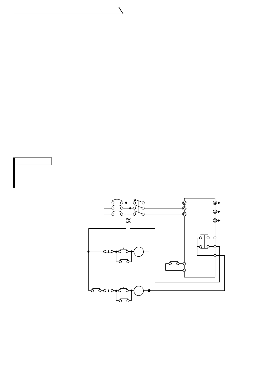
As shown on the right,
always use the start signal
(ON or OFF across
terminals STF or STR-SD)
Power
supply
to make a start or stop.
(Refer to page 28)
*1. When the power supply
is 400V class, install a
step-down transformer.
MC
(2) Handling of output side magnetic contactor
In principle, do not provide a magnetic contactor between the inverter and motor and
switch it from off to on during operation. If it is switched on during inverter operation, a
large inrush current may flow, stopping the inverter due to overcurrent shut-off. When
an MC is provided for switching to the commercial power supply, for example, switch it
on/off after the inverter and motor have stopped.
NFB
Operation ready
OFF
Start/Stop
Operation
OFF
ON
MC
RA
MC
T (*1)
MC
RA
RA
Inverter Start/Stop Circuit Example
R/L1
S/L2
T/L3
Inverter
STF(STR)
SD
W
U
To
V
moto
A
B
C
16
Page 27
Main circuit terminals
1
WIRING
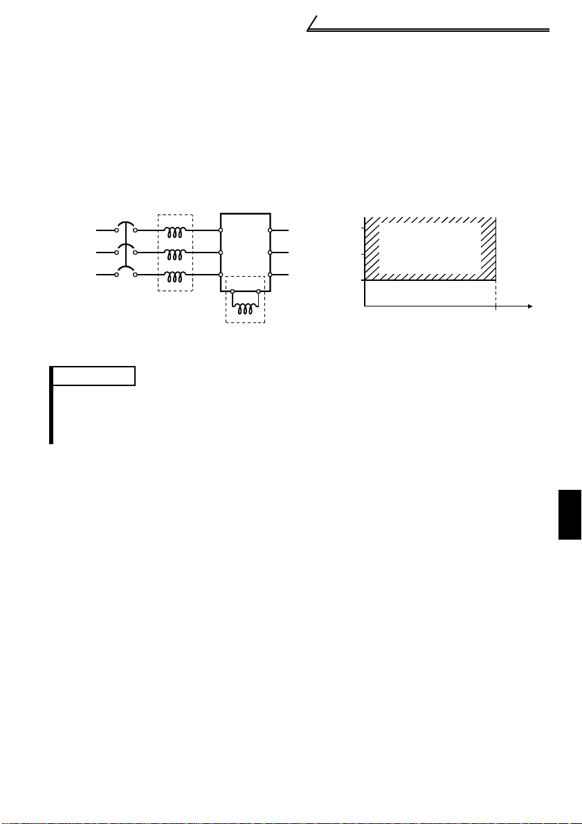
1.2.7 Regarding the installation of the power factor improving reactor
When the inverter is installed near a large-capacity power transformer (500kVA or
more with the wiring length of 10m or less) or the power capacitor is to be switched, an
excessive peak current will flow in the power supply input circuit, damaging the
converter circuit. In such a case, always install the power factor improving reactor (FRBEL(-H) or FR-BAL(-H)).
Power
supply
FR-BAL(-H)
NFB
R
S
TZ
Inverter
X
R
Y
S
T
P
FR-BEL(-H)(*)
P1
W
U
V
1500
1000
500
Power supply equipment
capacity (kVA)
Power factor
improving reactor
installation range
010
Wiring length (m)
REMARKS
*When connecting the FR-BEL(-H), remove the jumper ac ross terminals P- P1.
The wiring lengt h between t he FR-BEL(- H) and the i nverter should be 5m maxim um and as
short as possible.
Use the cables which are equal in size to those of the main circuit. (Refer to page 8)
17
Page 28
Main circuit terminals
1.2.8 Regarding noise and the installation of a noise filter
Some noise enters the inverter causing it to malfunction and others are generated by
the inverter causing the malfunction of peripheral devices. Though the inverter is
designed to be insusceptible to noise, it handles low-level signals, so it requires the
following general countermeasures to be taken.
(1) General countermeasures
• Do not run the power cables (I/O cables) and signal cables of the inverter in parallel
with each other and do not bundle them.
• Use twisted shield cables for the detector connecting and control signal cables and
connect the sheathes of the shield cables to terminal SD.
• Earth (Ground) the inverter, motor, etc. at one point.
• Capacitances exist between the inverter's I/O wiring, other cables, earth (ground)
and motor, through which leakage currents flow to cause the earth leakage circuit
breaker, earth (ground) leakage relay and external thermal relay to operate
unnecessarily. To prevent this, take appropriate measures, e.g. set the carrier
frequency in Pr. 72 to a low value, use an earth (ground) leakage circuit breaker
designed for suppression of harmonics and surges, and use the electronic thermal
relay function built in the inverter.
• The input and output of the inverter main circuit include high-degree harmonics,
which may disturb communication devices (AM radios) and sensors used near the
inverter. In this case, install a FR-BIF(-H) optional radio noise filter (for use on the
input side only) or FR-BSF01 line noise filter to minimize interference.
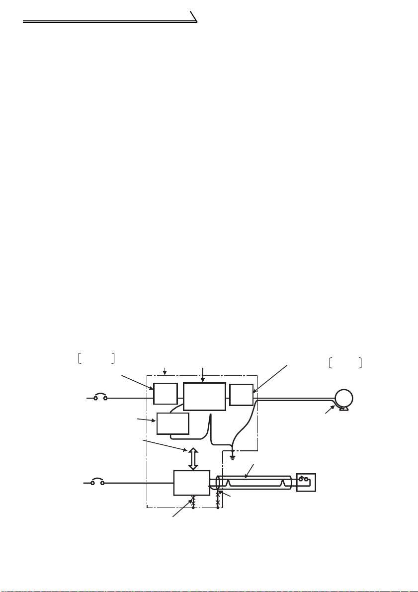
<Noise reduction examples>
Install filter
on inverter's input side.
Inverter
power supply
Separate inverter and power
line by more than 30cm and
at least 10cm from sensor
circuit.
Control
power supply
FR-BSF01
Install filter FR-BIF
on inverter's input side.
Do not earth (ground)
control box directly.
Do not earth (ground)
control cable.
Control
box
FRBSF01
FR-BIF
Reduce carrier
frequency.
Inverter
Power
supply
for sensor
18
Install filter
on inverter's output side.
FRBSF01
Use 4-core cable for motor
power cable and use one
cable as earth (ground) cable.
Use twisted pair shielded cable.
Do not earth (ground) shield but connect
it to signal common cable.
Sensor
FR-BSF01
IM
Motor
Page 29
Main circuit terminals
1
WIRING
1.2.9 Earthing (Grounding) precautions
Leakage currents flow in the inverter. To prevent an electric shock, the inverter and
motor must be earthed (grounded). Earthing (grounding) must conform to the
requirements of national and local safety regulations and electrical codes.
(JIS, NEC section 250, IEC 536 class 1 and other applicable standards)
Use the dedicated earth (ground) terminal to earth (ground) the inverter. (Do not use
the screw in the casing, chassis, etc.)
Use a tinned* crimping terminal to connect the earth (ground) cable. When
tightening the screw, be careful not to damage the threads.
*Plating should not include zinc.
Use the thickest possible earth (ground) cable. Use the cable whose size is equal to
or greater than that indicated in the following table, and minimize the cable length.
The earthing (grounding) point should be as near as possible to the inverter.
Motor Capacity
2.2kW or less 2 (2.5) 2 (2.5)
3.7kW 3.5 (4) 2 (4)
Earth (Ground) Cable Size (Unit: mm
200V class, 100V class 400V class
2
)
For use as a product compliant with the Low Voltage Directive, use PVC cable
whose size is indicated within parentheses.
Earth (Ground) the motor on the inverter side using one wire of the 4-core cable.
19
Page 30
Main circuit terminals
Inverter
NFB
Do not provide power factor
improving capacit or.
Motor
IM
FR-BEL(-H)
FR-BAL(-H)
FR-BAL
FR-BEL
1.2.10 Power supply harmonics
The inverter may generate power supply harmonics from its converter circuit to affect
the power generator, power capacitor etc. Power supply harmonics are different from
noise and leakage currents in source, frequency band and transmission path. T ake the
following countermeasure suppression techniques.
The following table indicates differences between harmonics and noise:
Item Harmonics Noise
Frequency
Environment To-electric channel, power impedance To-space, distance, wiring path
Quantitative
understanding
Generated amount Nea rly proportional t o load capacity
Affected equipment
immunity
Suppression example Provide reactor. Increase distance.
Suppression technique
Harmonic currents produced
on the power supply side by
the inverter change with such
conditions as whether there
are wiring impedances and a
power factor improving reactor
(FR-BEL(-H) or FR-BAL(-H))
and the magnitudes of output
frequency and output current
on the load side.
For the output frequency and output current, we understand that they should be
calculated in the conditions under the rated load at the maximum operating frequency.
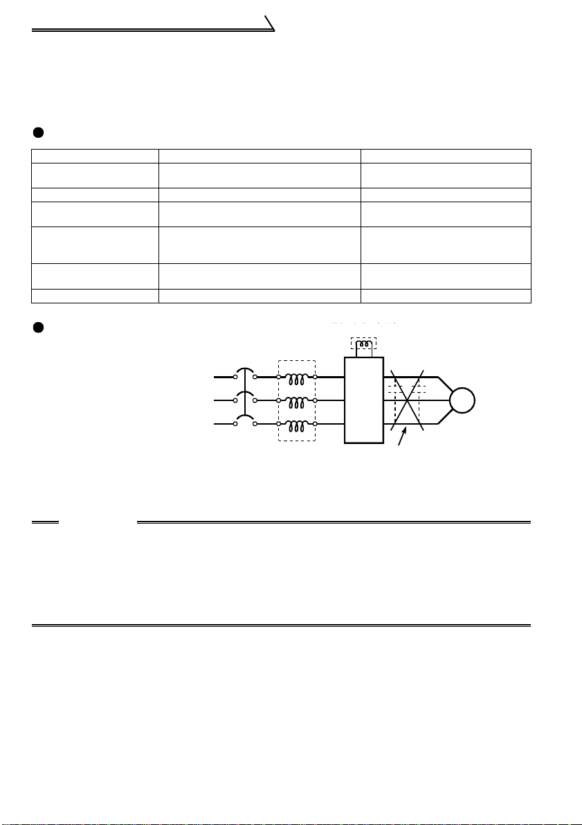
CAUTION
The power factor improving capacitor and surge suppressor on the inverter
output side may be overheated or dama ged by the har moni c co mponents of the
inverter output. Also, since a n exces sive c urr ent flows in the inverter to activa te
overcurrent protection, do not provide a capacitor and surge suppressor on the
inverter output side when the motor is driven by the inverter. To improve the
power factor, insert a power factor improving reactor on the inverter's primary
side or DC circuit. For full information, refer to page 17.
Normally 40th to 50th degrees or less
(up to 3kHz or less)
Theoretical calculation possible
Specified in standard per equipment
High frequency (several 10kHz
to 1GHz order)
Random occurrence,
quantitative grasping difficult
Change with current variation
ratio (larger as switching speed
increases)
Different depending on maker's
equipment specifications
20
Page 31

Main circuit terminals
1
WIRING
Not more than
reference capacity
New installation/addition/
renewal of equipment
Calculation of equivalent
capacity sum
Sum of equivalent
capacities
Over reference
capacity
Calculat io n of outgoing
harmonic current
Is outgoing harmonic
current equal to or lower
than maximum valu e?
Not more than
maximum value
Harmonic suppression
technique is not required.
Over maximum value
Harmonic suppression
technique is required.
1.2.11 Harmonic suppression guideline
Harmonic currents flow from the inverter to a power receiving point via a power
transformer. The harmonic suppression guideline was established to protect other
consumers from these outgoing harmonics.
The transistorized inverter has been excluded from the target products covered by
"harmonic suppression guideline for household appliances and general-purpose
products" in January 2004. In addition, all models of transistorized inverter used by
specific consumers are covered by "harmonic suppression guideline for consumers
who receive high voltage or special high voltage" (hereinafter referred to as "guideline
for specific consumers").
"Guideline f or spec ific c ons umers"
This guideline sets forth the maximum values of harmonic currents outgoing from a
high-voltage or spec i all y high-v ol ta ge con sume r who wi ll ins t all , add or rene w harm onic
generating equipment. If any of the maximum values is exceeded, this guideline
requires that c onsume r to t ak e cert ai n supp ressi on me asures .
T able 1 Maximum Values of Outgoing H armonic Curr ent s per 1 kW Contract Power
Received Power Voltage 5th 7th 11th 13th 17th 19th 23rd
6.6 kV 3.5 2.5 1.6 1.3 1.0 0.9 0.76 0.70
22 kV 1.8 1.3 0.82 0.69 0.53 0. 47 0.39 0.36
33 kV 1.2 0.86 0.55 0.46 0.35 0.32 0.26 0.24
(1) Application of the guideline for specific consumers
Over
23rd
21
Page 32

Main circuit terminals
Table 2 Conversion Factors for FR-S500 Series
Circuit Type Conversion Factor (Ki)
Without reactor K31 = 3.4
Three-phase bridge
(Capacitor-smoothed)
Single-phase bridge
(capacitor smoothed)
* K42=0.35 is a value when the reactor value is 20%. Since a 20% reactor is large and
considered to b e not prac tical , K42=1. 67 is wr itte n as c onversi on fa ctor f or a 5% react or in
the technica l data JEM-TR2 01 of the Japan Electric Machin e Industry Associati on and th is
value is recommended for calculation for the actual practice.
With reactor (AC side) K32 = 1.8
With reactor (DC side) K33 = 1.8
With reactors (AC, DC sides) K34 = 1.4
Without reactor K41 = 2.3
With reactor (AC side) K42 = 0.35 *
Table 3 Equivalent Capacity Limits
Received Power Voltage Reference Capacity
6.6kV 50 kVA
22/33 kV 300 kVA
66kV or more 2000 kVA
Table 4 Harmonic Contents (Values of the fundamental current is 100%)
Reactor 5th 7th 11th 13th 17th 19th 23rd 25th
Not used 65 41 8.5 7.7 4.3 3.1 2.6 1.8
Three-phase
bridge
(capacitor
smoothed)
Single-phase
bridge
(capacitor
smoothed)
* The harm onic contents for "single-phase bridge/with reactor" in the table 4 are values when
the reactor val ue is 20%. Since a 20% reactor is lar ge and cons idered to be not pract ical,
harmonic con tents when a 5% reactor is used is writte n in the technical data JEM-TR201 of
the Japan Electric Machine Industry Association and this value is recommended for
calculation for the actual practice.
Used (AC side) 38 14.5 7.4 3.4 3.2 1.9 1.7 1.3
Used (DC side ) or
with filter pack
Used (AC, DC
sides)
Without reactor 50 24 5.1 4.0 1.5 1.4
With reactor (AC
side) *
30 13 8.4 5.0 4.7 3.2 3.0 2.2
28 9.1 7.2 4.1 3.2 2.4 1.6 1.4
6.0 3.9 1.6 1.2 0.6 0.1
1) Calculation of equivalent capacity (P0) of harmonic generating equipment
The "equivalent capacity" is the capacity of a 6-pulse converter converted from the
capacity of consumer's harmonic generating equipment and is calculated with the
following equation. If the sum of equivalent capacities is higher than the limit in
Table 3, harmonics must be calculated with the following procedure:
P0=Σ (Ki × Pi) [kVA]
Ki: Conversion factor (refer to Table 2)
Pi: Input rated capacity of harmonic
generating equipment* [kVA]
i: Number indicating the conversion
circuit type
*Input rated capacity: Determined by
the capacity of the applied motor and
found in Table 5. It should be noted
that the rated capacity used here is
used to calculate a generated
harmonic amount and is different
from the power supply capacity
required for actual inverter drive.
22
Page 33

Main circuit terminals
1
WIRING
2) Calculation of outgoing harmonic current
Outgoing harmonic current = fundamental wave current (value converterd from
received power voltage) × operation ratio × harmonic
content
• Operation ratio: Operation ratio = actual load factor × operation time ratio during
30 minutes
• Harmonic content: Found in Table 4.
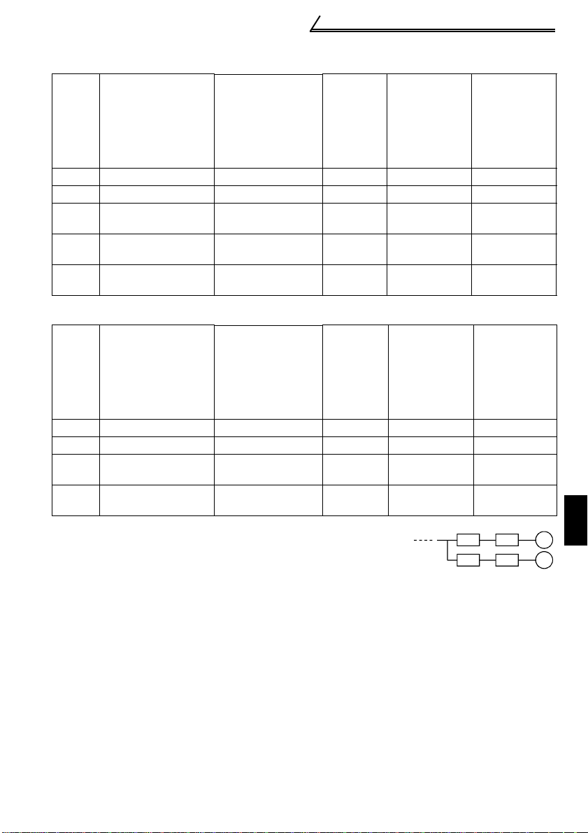
Table 5 Rated Capacities and Outgoing Harmonic Currents for Inverter Drive
Applied
Motor
(kW)
0.4 1.61 0.81 49 0.57 14.7 6.37 4.12 2.45 2.30 1.57 1.47 1.08
0.75 2.74 1.37 83 0.97 24.9 10.76 6.97 4.15 3.90 2.66 2.49 1.83
1.5 5.50 2.75 167 1.95 50.10 21.71 14.03 8.35 7.85 5.34 5.01 3.67
2.2 7.93 3.96 240 2.81 72.00 31.20 20.16 12.00 11.28 7.68 7.20 5.28
3.7 13.0 6.50 394 4.61 118.2 51.2 33.10 19.70 18.52 12.61 1 1.82 8.67
Rated
Current [A]
200V 400V 5th 7th 11th 13th 17th 19th 23rd 25th
6.6kV
Equivalent of
fundamental
wave input
current (mA)
Input
rated
capacity
(kVA)
Outgoing Harmonic Current Converted from
6.6kV (mA)
(without reactor, 100% operation ratio)
3) Harmonic suppression technique requirement
If the outgoing harmonic current is higher than; maximum value per 1kW (contract
power) × contract power, a harmonic suppression technique is required.
4) Harmonic suppression techniques
No. Item Description
Reactor inst a llation
1
(ACL, DCL)
Installation of power
2
factor improving
capacitor
Transformer multiphase operation
3
Passive
4
(AC filter)
Active filter This filter detects the current of a circui t generating a harm o nic
5
Install a reactor (ACL) in the AC side of the inverter or a reactor
(DCL) in its DC side or bo th to suppress outgoing harmonic
currents.
When used with a series reactor, the power factor i m proving
capacitor has an effect of absorbing harmonic currents.
Use two transformers with a phase angle difference of 30
∆, ∆-∆ combination to provide an effect corresponding to 12 pulses,
reducing low-degree harmonic currents.
A capacitor and a reactor are used together to reduce impedances
at specific freq u en cies, producing a great effect of abs o rb i n g
harmonic currents.
current and gen erates a ha rmonic cu rrent equ ivalent to a diff erence
between that current and a fundamental wave current to suppress
a harmonic current at a detection poi n t, providing a great effect of
absorbing harmonic currents.
23
° as in -
Page 34

Main circuit terminals
1.2.12 Inverter-driven 400V class motor
In the PWM type inverter, a surge voltage attributable to wiring constants is generated
at the motor terminals. Especially for a 400V class motor, the surge voltage may
deteriorate the insulation. When the 400V class motor is driven by the inverter,
consider the following measures:
•Measures
It is recommended to take either of the following measures:
(1) Rectifying the motor insulation
For the 400V class motor, use an insulation-enhanced motor. Specifically
1) Specify the "400V class inverter-driven, insulation-enhanced motor".
2) For the dedicated motor such as the constant-torque motor and low-vibration
motor, use the "inverter-driven, dedicated motor".
CAUTION
When the wiring length between the motor and inverter is 40m or more, take
the above countermeasure and also set the long wiring mode in Pr. 70 "SoftPWM setting". (Refer to page 107 for Pr. 70.)
(2) Suppressing the surge voltage on the inverter side
On the secondary side of the inverter, connect the optional surge voltage
suppression filter (FR-ASF-H).
24
Page 35

How to use the control circuit terminals
1
WIRING
1.3 How to use the control circuit terminals
1.3.1 Terminal block layout
In the control circuit of the inverter, the terminals are arranged as shown below:
Terminal arrangement
of control circuit
10 2 5 4
RUN
PC SE
A BC
Terminal screw
size: M3
Tightening torque: 0.5N m to 0.6N m
SD SD STF
Wire size: 0.3mm
STR
Terminal screw size: M2
Tightening torque: 0.22N m to 0.25N m
RM RH
RL FM
2
to 0.75mm
2
1.3.2 Wiri ng instructions
1) Terminals SD, SE and 5 are common to the I/O signals isolated from each other. Do
not earth them.
Avoid connecting the terminal SD and 5 and the terminal SE and 5.
2) Use shielded or twisted cables for connection to the control circuit terminals and run
them away from the main and power circuits (including the 200V relay sequence
circuit).
3) The input signals to the control circuit are micro currents. When contacts are
required, use two or more parallel micro signal contacts or a twin contact to prevent
a contact fault.
*Information on bar terminals
Introduced products (as of Oct., 2003): Phoenix Contact Co.,Ltd.
Bar Terminal Model
T erminal Screw Size
(With Insulation
Sleeve)
M3 (A, B, C terminals)
M2
(Other than the above)
Al 0.5-6WH A 0.5-6 0.3 to 0.5
Al 0.75-6GY A 0.75-6 0.5 to 0.75
Al 0.5-6WH A 0.5-6 0.3 to 0.5
Bar terminal crimping terminal: CRIMPFOX ZA3 (Phoenix Contact Co., Ltd.)
Bar Terminal Model
(Without Insulation
Sleeve)
Wire Size (mm
2
)
CAUTION
When using the bar terminal (without insulation sleeve), use care so that the
twisted wires do not come out.
25
Page 36

How to use the control circuit terminals
1.3.3 Changing the control logic
The input signals are set to sink
logic.
To change the control logic, the
jumper connector under the setting
dial must be moved to the other
position.
Change the jumper connector
position using tweez ers , a p air of
long-nose pliers etc.
Change the jumper connector
position before switch ing power on.
CAUTION
•Make sure that the front cover is installed securely.
•The front cover is fitted with the capacity plate and the inverter unit with the
rating plate. Since these plates have the same serial numbers, always replace
the removed cover onto the original inverter.
•The sink-source logic change-over jumper connector must be fitted in only
one of those positions. If it is fitted in both positions at the same time, th e
inverter may be damaged.
1) Sink logic type
• In this logic, a signal switches on when a current flows from the corresponding signal
input terminal.
Terminal SD is common to the contact input signals. Terminal SE is common to the
open collector output signals.
Power supply
• Connecting a positive terminal of the
STF
STR
SD
R
R
external power supply for transistor
output to terminal PC prevents a
malfunction caused by an undesirable
current. (Do not connect terminal SD
of the inverter with terminal 0V of the
external power supply. When using
terminals PC-SD as a 24VDC power
supply, do not install an external
power supply in parallel with the
inverter. Doing so may cause a
malfunction in the inverter due to an
undesirable current.)
AY40
transistor
output module
26
RUN
1
2
9
9
10
24VDC SD
SE
24VDC
STF
STR
PC
Current flow
AX40Inverter
1
9
Inverter
R
R
24VDC
(SD)
Page 37

How to use the control circuit terminals
1
WIRING
AY80
transistor
output module
9
1
2
10
PC
STF
STR
SD
Inverter
24VDC
(SD)
24VDC
Current flow
2) Source logic type
• In this logic, a signal switches on when a current flows into the corresponding signal
input terminal.
Terminal PC is common to the contact input signals. For the open collector output
signals, terminal SE is a positive external power supply terminal.
AX80
1
R
Power
supply
PC
STF
Inverter
RUN
R
STR
R
R
SE
24VDC
9
• Connecting the 0V terminal of the
external power supply for transistor
output to terminal SD prevents a
malfunction caused by an undesirable
current.
27
Page 38

Input terminals
ON
NFB
Power
supply
Forward
rotation start
Reverse
rotation start
STF
STR (Pr.63= "- - -" )
Inverter
Output frequency
Time
2-wire type connection example
SD
R, S, T
Across
STF-SD
(STR)
1.4 Input terminals
1.4.1 Run (start) and stop (STF, STR, STOP)
To start and stop the motor, first switch on the input power supply of the inverter
(switch on the magnetic contactor, if any, in the input circuit during preparation for
operation), then start the motor with the forward or reverse rotation start signal.
(1) Two-wire type connection (STF, STR)
A two-wire type connection is shown
on the right.
1) The forward/reverse rotation
signal is used as both the start
and stop signals. Switch on
either of the forward and reverse
rotation signals to start the motor
in the corresponding direction.
Switch on both or switch off the
start signal during operation to
decelerate the inverter to a stop.
2) The frequency setting signal may
either be given by entering 0 to
5VDC (or 0 to 10VDC) across
frequency setting input terminals
2-5 or by setting the required
values in Pr. 4 to Pr. 6 "multispeed setting" (high, middle, low
speeds). (For multi-speed
operation, refer to page 32.)
3) After the start signal has been input, the inverter starts operating when the
frequency setting signal reaches or exceeds the "starting frequency" set in Pr. 13
(factory-set to 0.5Hz).
If the motor load torque is large or the "torque boost" set in Pr . 0 is small , operation
may not be started due to insufficient torque until the inverter output frequency
reaches about 3 to 6Hz.
If the "minimum frequency" set in Pr. 2 (factory setting = 0Hz) is 6Hz, for example,
merely entering the start signal causes the running frequency to reach the
minimum frequency of 6Hz according to the "acceleration time" set in Pr. 7.
4) To stop the motor, operate the DC injection brake for the period of "DC injection
brake operation time" set in Pr. 11 (factory setting = 0.5s) at not more than the DC
injection brake operation frequency or at not more than 0.5Hz.
To disable the DC injection brake function, set 0 in either of Pr. 11 "DC injection
brake operation time" or Pr. 12 "DC injection brake voltage".
In this case, the motor is coasted to a stop at not more than the frequency set in
Pr. 10 "DC injection brake operation frequency" (0 to 120Hz variable) or at not
more than 0.5Hz (when the DC injection brake is not operated).
5) If the reverse rotation signal is input during forward rotation or the forward rotation
signal is input during reverse rotation, the inverter is decelerated and then
switched to the opposite output without going through the stop mode.
28
Page 39

1
WIRING
Input terminals
(2) Three-wire type connection (STF, STR, STOP)
A three-wire type connection is shown on
the right. Assign the start self-holding
signal (STOP) to any of the i nput terminals.
To make a reverse rotation start, set Pr. 63
Power
supply
to "- - -" (factory setting).
1) Short the signals STOP-SD to enable
the start self-holding function. In this
case, the forward/reverse rotation signal
functions only as a start signal.
(Note) Assign the stop signal to any of
Pr. 60 to Pr. 62 (input terminal
function selection).
2) If the start signal terminals STF (STR)-
SD are shorted once, then opened, the
start signal is kept on and starts the
inverter. To change the rotation direction,
short the start signals STR (STF)-SD
once, then open it.
3) The inverter is decelerated to a stop by
opening the signals STOP-SD once. For
the frequency setting signal and the
operation of DC injection brake at a stop
time, refer to paragraphs 2) to 4) in (1)
Two-wire type connection. The right
diagram shows 3-wire type connection.
4) When the signals JOG-SD are shorted, the STOP signal is invalid and the JOG
signal has precedence.
5) If the output stop signals MRS-SD are shorted, the self-holding function is not
deactivated.
DC Injection Brake and Coasting to Stop Functionality
Operation
Mode
DC Injection
Brake
DC injection
brake enabled
DC injection
brake disabled
External Operation or Combined
Terminals STF
(STR)-SD
disconnected
DC injection br ak e
operated at not
more than "DC
injection brak e
operation
frequency" set in
Pr. 10
Coasted to a stop
at not more than
"DC injection
brake operation
frequency" set in
Pr. 10
*1: Also stopped by the . Refer to page 109.
Operation
Pr. 79 = "0", "2", "3"
Set frequency
(*1)
changed to 0Hz
DC injection brake
operated at 0.5Hz
or less.
Coasted to a stop
at 0.5Hz or less.
STOP
RESET
NFB
Forward
rotation start
Stop
Reverse
rotation start
Output frequency
Start
Stop
3-wire type connectio n example
DC injection brake
operated at not
more than "DC
injection brak e
operation
frequency" set in
Pr. 10
Coasted to a stop
at not more than
"DC injection
brake operatio n
frequency" set in
Pr. 10
ON
PU Operation or Comb in ed
Pr. 79 = "0 ", "1 ", "4"
Stop key
R, S, T
Inverter
STF
STR (Pr.63= "- - -" )
STOP
SD
Operation
DC injection brake
operated at 0.5Hz
or less.
Coasted to a stop
at 0.5Hz or less.
Time
ON
Set frequency
changed to 0Hz
29
Page 40

Input terminals
Output frequency
Starting
frequency
Pr.13
(*1)
0.5Hz
Forward
rotation
Forward
rotation
3Hz
3Hz
Start signal switched on
while DC injection brake
is being operated
DC injection brake operation
frequency Pr. 10
DC injection
brake enabled
Time
DC injection brake
operation time Pr. 11
0.5s
ON
ON ON
ON
Revers e
rotation
0.5Hz
Start
signal
terminal
(*3)
(*4)
Across
STF-SD
Across
STR-SD
Start signal
terminal
Across STF-SD
Across STR-SD
DC injection brake disabledDC injection brake enabled
Starting frequency
Pr.13
(*1)
0.5Hz
Output frequency
ON
DC injection brak e
operation
frequency Pr. 10
3Hz
0.5Hz
0.5s
DC injection
brake operation
time Pr. 11
(*3)
(*2)
DC injection
brake operation
time Pr. 11
ON
0.5Hz
0.5s
(*3)
Start/Stop Timing Chart (for two-wire type)
DC injection brake
not operate d
ON
(*4)
3Hz
Coasted to
a stop
Time
Forward-Reverse Rotation Switch-Over Timing Chart
REMARKS
*1. The "starting frequency" in Pr. 13 (factory-set to 0.5Hz) m ay be set between 0 and 60Hz.
*2. If the next start signal is gi ve n duri ng DC inj ect ion bra ke oper at ion, the D C inje ct ion br ake
is disabled and re start is made.
*3. The "DC injection brak e ope rat io n time " in Pr. 11 (factory-set to 0.5s) may be se t be t ween
0 and 10s.
*4. The frequency at whic h the mot or is coas ted to a st op is not more tha n the "DC injec tion
brake operation frequency" set in Pr. 10 (factory setting = 3Hz; may be set b e tween 0 and
120Hz) or not more than 0.5Hz.
*5. The "starting frequen cy" in Pr. 13, "DC injection brake operati on time" in Pr. 11 and "DC
injection brake operation frequency" in Pr. 10 are the factory-set values.
30
Page 41

Input terminals
1
WIRING
Maximum frequency
(0 to 120Hz)
Minimum frequency
(0 to 120Hz)
Starting frequency
(0 to 60Hz)
0.5
0
Output frequencies
(Hz)
Input voltage is
proportional to
output
frequency.
Pr.38
Pr.39
Pr.1
Pr.2
Pr.13
Pr.73
5V
(10V)
(20mA)
Frequency setting signal
Frequency setting
voltage gain frequency
Frequency setting
current gain frequency
(1 to 120Hz)
1.4.2 Connection of frequency setting potentiometer and output frequency meter (10, 2, 5, 4, AU)
The analog frequency setting input signals that may be entered are voltage and
current signals.
For the relationships between the frequency setting input voltages (currents) and
output frequencies, refer to the following diagram. The frequency setting input signals
are proportional to the output frequencies. Note that when the input signal is less than
the starting frequency, the output frequency of the inverter is 0Hz.
If the input signal of 5VDC (or 10V, 20mA) or higher is entered, the output frequency
does not exceed the maximum output frequency.
Relationships between Frequency Setting Inputs and Output Frequencies
REMARKS
For the way to calibrate the output frequency meter, refer to page 131.
(1) Voltage input (10, 2, 5)
Enter the frequency setting input signal of 0 to 5VDC (or 0 to 10VDC) across the
frequency setting input terminals 2-5. The maximum output frequency is reached
when 5V (10V) is input across terminals 2-5.
The power supply used may either be the inverte r's b uilt-in p ower supply or an exter nal
power supply. For the built-in power supply, terminals 10-5 provide 5VDC output.
For operation at 0 to 5VDC, set "0" in
Pr. 73 to the 0 to 5VDC input. Use
terminal 10 for the built-in power
supply.
0 to 5VDC
+5V 10
2
5
For operation at 0 to 10VDC, set "1" in
Pr. 73 to the 0 to 10VDC input.
2
5
31
0 to 10VDC
Page 42

Input terminals
REX
Speed 1
(high speed)
Speed 5
Speed 6
Speed 7
Time
ON ON ON ON
RM
ONONON
RL
RH
ON ON ON ON
Output frequency (Hz)
(low speed)
Speed 3
Speed 2
(middle speed)
Speed 4
(2) Current input (4, 5, AU)
To automatically perform operation under constant pressure or temperature control
using a fan, pump etc., enter the controller output signal of 4 to 20mADC across
terminals 4-5.
Terminals AU-SD must be shorted to use the 4 to 20mADC signal for operation.
(Assign the signal AU using any of Pr. 60 to Pr. 63.)
When the multi-speed signal is input, the current input is ignored.
Automatic/manual
signal switching
Manual operation
Frequency setting
potentiometer
Automatic signal
4-20mADC
AU
SD
10
2
Inverter
5
4
Manual-Automatic Switching
Across
AU-SD
Operation
Automatic
operation
4 to 20mA
OFFON
Manual
operation
0 to 5V
(0 to 10V)
1.4.3 E xternal frequency selection (REX, RH, RM, RL)
Up to 15 speeds (*) may be selected for an external command forward rotation start or
up to 7 speeds for an external command reverse rotation start according to the
combination of connecting the multi-speed select terminals REX, RH, RM and RL-SD,
and multi-speed operation can be performed as shown below by shorting the start
signal terminal STF (STR)-SD.
Speeds (frequencies) may be specified as desired from the operation panel or
parameter unit as listed below.
CAUTION
• * C hange the setting of Pr. 63 "STR terminal function selection" to "8", and
assign and use as the 15-speed select signal (REX).
Has precedence over the main speed setting signal (0 to 5V, 0 to 10V, 4 to
20mADC).
32
RH
RM
RL
REX
Speed 10
Speed 11
Speed 9
Speed 8
Output frequency (Hz)
ON ON ON ON
ON ON ON ON
ONON ON ON ON ON ON ON
Speed 12
Speed 13
Speed 14
Speed 15
Time
ON ON ON ON
Page 43

Input terminals
1
WIRING
ONONONONONONONONONONONONONONONONONONONONONONONONONONONONONONON
ON
Multi-Speed Setting
Terminal Input
REX-
Speed
Speed 1
(high
speed)
Speed 2
(middle
speed)
Speed 3
(low
speed)
Speed 4 OFF OFF Pr. 24
Speed 5 OFF OFF Pr. 25 Pr. 6 setting when Pr. 25="- - -"
Speed 6 OFF OFF Pr. 26 Pr. 5 setting when Pr. 26="- - -"
Speed 7 OFF Pr. 27 Pr. 6 setting when Pr. 27="- - -"
Speed 8 OFF OFF OFF Pr. 80 0Hz when Pr. 80="- - -"
Speed 9 OFF OFF Pr. 81 Pr. 6 setting when Pr. 81="- - -"
Speed 10 OFF OFF Pr. 82 Pr. 5 setting when Pr. 82="- - -"
Speed 11 OFF Pr. 83 Pr. 6 setting when Pr. 83="- - -"
Speed 12 OFF OFF Pr. 84 Pr. 4 setting when Pr. 84="- - -"
Speed 13 OFF Pr. 85 Pr. 6 setting when Pr. 85="- - -"
Speed 14 OFF Pr. 86 Pr. 5 setting when Pr. 86="- - -"
Speed 15 Pr. 87 Pr. 6 setting when Pr. 87="- - -"
External
setting
RH-SDRM-SDRL-
SD*
OFF OFF OFF Pr. 4 0 to 120Hz
OFF OFF OFF Pr. 5 0 to 120Hz
OFF OFF OFF Pr. 6 0 t o 120Hz
OFF OFF OFF OFF
Parameter
SD*
Frequency
setting
potentiometer
Set Frequency
Range
0 to 120Hz, - - -
0 to max. setting
Remarks
Pr. 6 setting when Pr. 24="- - -"
*When using the REX signal, an external command cannot be used to make a
reverse rotation start.
10
U
V
W
2
5
IM Motor
*1
Frequency
setting
potentiometer
Power supply
Forward rotation
Multi-speed
selection
R
S
T
STF
REX
RH
RM
RL
SD
Inverter
*2
Multi-Speed Operation Connection Example
REMARKS
*1. When the freq uency s ettin g pot entio meter is co nnect ed, t he i nput s igna l of the freque ncy
setting potenti ometer is ignore d if th e multi-s peed sele ct signa l is switc hed on. (Th is als o
applies to the 4 to 20m A input signal.)
*2. For a reverse rotation star t, set Pr. 63 to "- - -" (fa ctory se ttin g) to make the STR s ignal of
terminal STR valid.
33
Page 44

Input terminals
r
1.4.4 Indicator connection and adjustment (FM)
The output frequency, etc. of the inverter can be indicated by a DC ammeter of 1mA
full-scale deflection and maximum 300Ω internal resistance or a commercially
available digital indicator which is connected across terminals FM-SD.
The indicator can be calibrated from the operation panel or parameter unit. Note that
the reading varies according to the wiring distance if the indicator is placed away from
the inverter. In this case, connect a calibration resistor in series with the indicator as
shown below and adjust until the reading matches the operation panel or parameter
unit indication (indicator monitoring mode).
Install the indicator within 200m (50m for the digital indicator) of the inverter and
connect them by at least 0.3mm
Inverter
Calibration re s is t o r *
FM
1mA
SD
REMARKS
* Not needed when calibration is made using the calibration parameter C1 "FM terminal
calibration". T his res istor is used when calib ration mu st be ma de near th e freque ncy mete r
for such a reason as a remote frequency meter. Note that the needle of the fr equency meter
may not deflect to full-scale when th e c a lib ra tion resistor is c on ne c te d. In this case, us e both
the resistor and calibration parameter "C1".
CAUTION
•Refer to page 131 for the procedure of indicator adjustment.
2
twisted or shielded cables.
Inverter
(+)
Analog
indicator
(-)
(1mA full-scale)
FM
SD
T ypes of Indicators Connected
1440 pulses/s
Digital indicato
34
Page 45

Input terminals
1
WIRING
Output waveform of terminal FM
The output signal of terminal FM has a pulse waveform as shown in the table below
and the number of its pulses is proportional to the inverter output frequency.
The output voltage (average voltage) is also proportional to the output frequency.
Terminal FM Output Voltage
Specifications
Output
Calibration parameter C1 (Pr. 900)
waveform
8V
Max. 2400 pulses/s
Number of
output
pulses
(pulses/
second)
Output
voltage
*1. 0.5V or l ess when a DC ammeter of 300Ω or less intern al resistance is connected to
Set a full-scale value which
achieves 1440 pulses/s.
Pr. 55: frequency monitoring
reference
Pr. 56: cu rrent monitoring
reference
0 to 8VDC max. (*1)
(Approx. 5V at 1440 pulses/s)
measure the ou tput voltage.
Inverter
24V
FM
SD
FM
Example of Inverter and Frequency
Meter
Adjustment
• Analog meter
To adjust the reading of an analog indicator (ammeter), turn the calibration resistor to
change the current.
When using the operation panel or parameter unit for adjustment, change the pulse
width of the output waveform (calibration parameter "C1") (adjust the current through
the adjustment of the output voltage) to adjust the reading. (For details, refer to page
131.)
REMARKS
It is not recommended to use a voltage type indicator because it is easily affected by a voltage
drop, induction noise, etc. and may not provide correct reading if the wiring distance is long.
35
Page 46

Input terminals
• Digital indicator
Since the digital indicator counts and displays the number of pulses, adjust it from
the operation panel or parameter unit.
The inverter output, at which the reference pulses of 1440 pulses/s are output, can
be set in Pr. 55 when frequency monitoring is used as reference, or in Pr. 56 when
current monitoring is used as reference.
[Example]1. To set the output across FM-SD to 1440 pulses/s at the inverter output
frequency of 120Hz, set "120" (Hz) in Pr. 55. (Factory setting: 60Hz)
2. To set the output across FM-SD to 1440 pulses/s at the inverter output
current of 15A, set "15" (A) in Pr. 56. (Factory setting: rated inverter
current)
1.4.5 Cont rol circuit common terminals (SD, 5, SE)
Terminals SD, 5, and SE are all common terminals (0V) for I/O signals and are isolated
from each other.
Terminal SD is a common terminal for the contact input terminals (STF, STR, RH, RM,
RL) and frequency output signal (FM).
Terminal 5 is a common terminal for the frequency setting analog input signals. It
should be protected from external noise using a shielded or twisted cable.
Terminal SE is a common terminal for the open collector output terminal (RUN).
1.4.6 Signal inputs by contactless switches
If a transistor is used instead of a
contacted switch as shown on the
+24V
right, the input signals of the
inverter can control terminals STF,
STR, RH, RM, RL.
STF, etc.
Inverter
SD
External signal input using transistor
REMARKS
1.When us ing an extern al transis tor con nected to an ext ernal powe r suppl y, use terminal SD
to prevent a malfun c t io n fro m oc cu rring due to a leakage current. (Refer to page 26.)
2.Note that an SSR (solid-state relay) has a relatively large leakage current at OFF time and it
may be accidentally input to the inver ter.
36
Page 47

How to use the input signals (assigned terminals
1
WIRING
STF (STR)
RT
Inverter
Start
Second acceleration
/deceleration
SD
A
1.5 How to use the input signals (assigned terminals RL, RM, RH, STR)
RL, RM, RH, STR)
These terminals can be
changed in function by
setting Pr. 60 to Pr. 63.
Pr. 60 "RL terminal function selection"
Pr. 61 "RM terminal function selection"
Pr. 62 "RH terminal function selection"
Page 102
Pr. 63 "STR terminal function selection"
1.5.1 Mu lti-speed setting (RL, RM, RH, REX signals):
Pr. 60 to Pr. 63 setting "0, 1, 2, 8"
Remote setting (RL, RM, RH signals ):
Pr. 60 to Pr. 63 setting "0, 1, 2"
• By entering frequency commands into the RL, RM, RH and REX signals and turning
on/off the corresponding signals, you can perform multi-speed operation (15
speeds). (For details, refer to page 32.)
• If the operation panel is away from the control box, you can perform continuous
variable-speed operation with signal contacts, without using analog signals. (For
details, refer to page 99.)
1.5.2 Second function selection (RT signal): Pr . 60 to P r. 63 setting "3"
Pr. 44 "second acceleration/deceleration time"
Pr. 45 "second deceleration time"
Pr. 46 "second torque boost"
Pr. 47 "second V/F (base frequency)"
To set any of the above functions, turn on this
"RT signal".
1.5.3 Current input selection "AU signal": Pr. 60 to Pr. 63 setting "4"
used to perform operation
of constant- pressure/
temperature control,
automatic operation can
be performed by entering
When a fan, pump etc. is
the 4-20mADC output
signal of a regulator into
across terminals 4-5.
When the 4-20mADC signal is used to perform operation, always short the AU signal.
REMARKS
The current inp ut is ignored if the multi -speed signal is input .
Frequency setting
utomatic signal
Automatic/manual
signal switching
Manual operation
potentiometer
4-20mADC
37
AU
SD
10
2
5
4
Operation
Inverter
Across
AU-SD
ON
Automatic
operation
4 to 20mA
OFF
Manual
operation
0 to 5V
(0 to 10V)
Page 48

How to use the input signals (assigned terminals
Output frequency
Motor coasted
to stop
0.5Hz
Across
STF (STR)
ON
ON
Pr. 13
"starting
frequency"
Across
MRS-
SD
SD
RL, RM, RH, STR)
1.5.4 Start self-holding selection (STOP signal): Pr. 60 to Pr. 63
setting
"5"
This connection example is used when you want
to self-hold the start signal (forward rotation,
*
STOP
reverse rotation).
* Connected to the STOP signal to avoid
Stop
forward or reverse rotation if forward or
reverse rotation and stop are turned on
simultaneously.
Forward
rotation
Reverse
rotation
(Wiring example for sink logic)
SD
STF
STR
1.5.5 Output shut-off (MRS signal): Pr. 60 to Pr. 63 setting "6"
Short the output stop terminal MRS-SD during inverter output to cause the inverter to
immediately stop the output. Open terminals MRS-SD to resume operation in about
10ms. Terminal MRS may be used as described below:
(1) To stop the motor by
mechanical brake (e.g.
electromagnetic brake)
Terminals MRS-SD must be
shorted when the mechanical
brake is operated and be opened
before motor restart.
(2) To provide interlock to
disable operation by the
inverter
After MRS-SD have been shorted,
the inverter cannot be operated if
the start signal is given to the
inverter.
(3) To coast the motor to stop
The motor is decelerated according to the preset deceleration time and is stopped
by operating the DC injection brake at 3Hz or less. By using terminal MRS, the
motor is coasted to a stop.
38
Page 49

How to use the input signals (assigned terminals
1
WIRING
r
A
A
A
RL, RM, RH, STR)
1.5.6 External thermal relay input: Pr. 60 to Pr. 63 setting "7"
When the external thermal relay or thermal relay built in
the motor is actuated, the inverter output is shut off and
an alarm signal is given to keep the motor stopped to
protect the motor from overheat. Even if the thermal
relay contact resets, the motor cannot be restarted
unless the reset terminals RES-SD are shorted for more
Inverter
Thermal relay
U
V
W
OH
SD
Moto
IM
than 0.1s and then opened or a power-on reset is made.
The function may therefore be used as an external
emergency stop signal input.
1.5.7 J og operation (JOG signal): Pr. 60 to Pr. 63 setting "9"
(1) Jog operation using external signals
Jog operation can be started/stopped by shorting the jog mode select terminals JOGSD and shorting/opening the start signal terminals STF or STR-SD. The jog frequency
and jog acceleration/deceleration time are set in Pr. 15 (factory setting 5Hz, variable
between 0 and 120Hz) and Pr. 16 (factory setting 0.5s, variable between 0 and 999s),
respectively, and their settings can be changed from the operation panel or parameter
unit.
The JOG signal has precedence over the multi-speed signal. (External)
Jog frequency Pr. 15
DC injection brake
ON
3Hz
ON
Reverse
rotation
ON
Time
Forward
0.5Hz
rotation
Output frequency
cross JOG -
Forward rotation
cross STF-
Reverse rotation
cross STR-
SD
SD
SD
39
Page 50

How to use the input signals (assig ne d ter m in als
Across RES Across
STF (STR)-
ON
ON
Coasting
When motor is restarted
during coasting, inverter
activates current limit to
start acceleration.
Coasting to stop
(Indicates motor speed)
Coasting time
ON
T
Ordinary
acceleration
T: Should be longer than the time of
coasting to stop.
Output frequency
(Hz)
SD
SD
RL, RM, RH, STR)
1.5.8 Reset signal: Pr. 60 to Pr. 63 setting "10"
Used to reset the alarm stop state established when the inverter's protective function
is activated. The reset signal immediately sets the control circuit to the initial (cold)
status, e.g. initializes the electronic thermal relay function protection circuit. It shuts off
the inverter output at the same time. During reset, the inverter output is kept shut off.
To give this reset input, short terminals RES-SD for more than 0.1s. When the shorting
time is long, the operation panel or parameter unit displays the initial screen, which is
not a fault.
After opening terminals RES-SD (about 1s), operation is enabled.
The reset terminal is used to reset the inverter alarm stop state. If the reset terminal is
shorted, then opened while the inverter is running, the motor may be restarted during
coasting (refer to the timing chart below) and the output may be shut off due to
overcurrent or overvoltage.
Setting either "1" or "15" in reset selection Pr. 75 allows the accidental input of the
reset signal during operation to be ignored.
(For details, refer to page 109.)
CAUTION
Frequent resetting will make electronic thermal relay function invalid.
40
Page 51

How to use the input signals (assigned terminals
1
WIRING
RL, RM, RH, STR)
1.5.9 PID control valid terminal:
Pr. 60 to Pr . 6 3 setting
"14"
To exercise PID control, turn on the X14 signal. When this signal is off, ordinary
inverter operation is performed. For more information, refer to page 117.
♦Related parameters♦
Pr. 88 "PID action selec tion ", Pr. 89 "PID propo rti on al ba nd ", Pr. 90 "PID i nte gr al t ime", Pr. 91
"PID upper limit", Pr. 92 "PID lower limit", Pr. 93 "PID action set point for PU operation", Pr. 94
"PID differential time" (Refer to page 117.)
1.5.10 PU operation/external operation switchover:
setting
"16"
Pr. 60 to Pr. 63
You can change the operation mode.
With "8" set in Pr. 79 "operation mode selection", turning on the X16 signal shifts the
operation mode to the external operation mode and turning off the X16 signal shifts it
to the PU operation mode. For details, refer to page 113.
♦Related parameters♦
Pr. 79 "operation mode selection" (Refer to page 113.)
41
Page 52

Connection to the Stand-Alone Option
FR-S520E-0.4K, 0.75K
PR
P/+
FR-S520E-1.5K to 3.7K
Brake resistor
Brake resistor
V
T/L3
N/-
PR
P/+
P1
1.6 Connection to the Stand-Alone Option
The inverter accepts a variety of stand-alone option units as required.
Incorrect connection will cause inverter damage or accident. Connect and operate the
option unit carefully in accordance with the corresponding option unit manual.
1.6.1 Connection of the dedicated external brake resistor (option) (FR-S520E-0.4K to 3.7K only)
REMARKS
A dedicated exte rnal brake resistor can be connected to the FR-S520E-0.4K to 3.7K .
Connect a brake resistor across terminals P/+ and PR. Connect a dedicated brake
resistor only. (For the locations of terminals P/+ and PR, refer to the terminal block
layout (page 6).)
CAUTION
If the transistors in the inverter should become faulty, the resistor can be
unusually hot, causing a fire. Therefore, install a magnetic contactor (MC) on
the inverter's power supply side to configure a circuit so that a current is shut
off in case of fault.
(For connection of the electro magnetic contactor, refer to page 16.)
42
Page 53

Connection to the St and-Alone Option
1
WIRING
Motor
Inverter
BU(-H) type brake unit
T(Caution 4)
MC
U
V
W
HCHBHA TB
P
OCR
PR
NFB
PC
ON
OFF
MC
OCR
N
MC
Remove
jumpers.
IM
Discharge resistor
Connect a
jumper.
Power
supply
(Caution 3)
R/L1
S/L2
T/L3
N/-
P/+
1.6.2 Connection of the brake unit (BU type)
Connect the BU type brake unit correctly as shown below. Incorrect connection will
damage the inverter. Remove jumpers across terminals HB-PC and TB-HC and
connect a jumper across terminals PC-TB of the brake unit.
CAUTION
1. The wiring distance between the inverter, brake unit and discharge resistor
should be within 2m. If twisted wires are used, the distance should be within
5m.
2. If the transistors in th e brake unit should b ecome faulty, the resistor can be
unusually hot, causing a fire. Therefore, install a magnetic contactor on the
inverter's power supply side to shut off a current in case of fault.
3. The N terminal is not provided for the FR-S520E-0.1K to 0.75K.
4. When the power supply is 400V class, install a step-down transformer.
43
Page 54

Connection to the Stand-Alone Option
1.6.3 Conne ction of the high power factor converter (FR-HC)
When connecting the high power factor converter (FR-HC) to suppress power supply
harmonics, perform wiring securely as shown below. Incorrect connection will damage
the high power factor converter and inverter.
Power
supply
(Caution 2)
MC1MC2
RSTR4S4T4 N
From FR-HCL02
MC2
MC1
NFB
High power factor converter (FR-HC)
P
R4S4T4
R3S3T3
External box
R2S2T2
FR-HCL01
S
R
T
(Caution 2)
Y1 or Y2 RDY RSO SE
(Caution 5)
Inverter
R
(Caution 2)
S
T
(Caution 1)
SD
RES (Caution 4)
MRS (Caution 4)
P
(Caution 6)
N
CAUTION
1. Use sink logic (factory setting) when the FR-HC is connected. The FR-HC
cannot be connected when source logic is selected.
2. The power input terminals R, S, T must be open. Incorrect connection will
damage the inverter. Opposite polarity of terminals N, P will damage the
inverter.
3. The voltage phases of terminals R, S, T and terminals R4, S4, T4 must b e
matched before connection.
4. Use Pr. 60 to Pr. 63 (input terminal function selection) to assign the terminals
used for the RES and MRS signals.
5. Do not insert NFB between terminals P-N (P - P, N - N)
6. The N terminal is not provided for the FR-S520E-0.1K to 0.75K.
44
Page 55

Connection to the St and-Alone Option
1
WIRING
A
1.6.4 Connection of the power regeneration common converter (FR-CV)
When connecting the FR-CV type power regeneration common converter, connect the
inverter terminals (P, N) and FR-CV type power regeneration common converter
terminals as shown below so that their signals match with each other.
Three-phase
C power
supply
NFB
MC1
Dedicated stand-alone
reactor (FR-CVL)
R/L11
S/L21
T/L31
R2/L12
S2/L22
T2/L32
FR-CV power regenerative
common converter
(Caution 2)
1
R2/L
2
S2/L
3
T2/L
(Caution 5)
R/L11
S/L21
T/MC1
P/L+
N/L-
P24
SD
RDYA
RDYB
RSO
SE
(Caution 4)
R
(Caution 1)
S
T
Inverter
P
N
(Caution 7)
PC
(Caution 6)
SD
MRS (Caution 3)
RES (Caution 3)
U
IM
V
W
CAUTION
1. Use sink logic (factory setting) when the FR-CV is connected. The FR-CV
cannot be connected when source logic is selected.
2. The power input terminals R, S, T must be open. Incorrect connection will
damage the inverter. Opposite polarity of terminals N, P will damage the
inverter.
3. The voltage phases of terminals R/L11, S/L21, T/MC1 and terminals R2/L1,
S2/L2, T2/L3 must be matched before connection.
4. Use Pr. 60 to Pr. 63 (input terminal function selection) to assign the terminals
used for the RES and MRS signals.
5. Do not insert NFB between terminals P-N (P/L+ - P, N/L− - N)
6. Make sure to connect the terminal R/L11, S/L21, T/MC1 to the power supply.
Running the inverter without connecting the terminals will damage the
power regeneration common converter.
7. The N terminal is not provided for the FR-S520E-0.1K to 0.75K.
45
Page 56

Handling of the RS-485 connector
1.7 Handling of the RS-485 connector
<RS-485 connector pin layout>
View A of the inverter (receptacle
side)
8) to 1)
View A
CAUTION
1. Do not plug the connector to a computer LAN port, fax modem socket,
telephone modular connector etc.. The product could be damaged due to
differences in electrical specifications.
2. Pins 2 and 8 (P5S) are provid ed for the parameter unit power su pply. Do not
use them for any other purpose or when making parallel connection by RS485 communication.
3. Refer to page 137 for the communication parameters.
1.7.1 Connection of the parameter unit (FR-PU04)
When connecting the parameter unit to the RS-485 connector, use the optional
parameter unit connection cable (FR-CB2 ).
CAUTION
When the parameter unit is used, the operation other than the stop key
STOP
( ) of the operation panel is disabled.
RESET
View A
1) SG
2) P5S
3) RDA
4) SDB
5) SDA
6) RDB
7) SG
8) P5S
Refer to page 156 for the parameters related to parameter unit setting.
46
Page 57

Handling of the RS-485 connector
1
WIRING
RS-485
connector
Inverter
Station 0
Computer
RS-485
interface/
terminal
10BASE-T cable 1)
RJ-45 connector 2)
RS-485
connector
Inverter
Station 0
Computer
10BASE-T cable 1)
RJ-45 connector 2)
RS-232C
cable
Max. 15m
RS-232C
connector
RS-232C RS-485
converter
Product Model Maker
1) 10BASE-T cable
SGLPEV-T 0.5mm
× 4P
* Do not use pins No. 2, 8 (P5S).
Mitsubishi Cable Industries, Ltd.
2) RJ-45 connector 5-554720-3 Tyco Electronics Corporation
1.7.2 Wiring of RS-485 communication
Use the RS-485 connector to perform communication operation from a personal
computer etc.
When the RS-485 connector is connected with a personal, FA or other computer
by a communication cable, a user program can run and monitor the inverter or
read and write to the parameters. For parameter setting, refer to page 135.
•Conforming standard: EIA-485 (RS-485)
•Transmission format: Multidrop link system
•Communication speed: Max. 19200bps
•Overall extension: 500m
Refer to page 135 for the setting related to RS-485 communication operation.
<System configuration examples>
(1) Connection of a computer to the inverter (1:1 connection)
Computer-inverter connection cable
Refer to the following for the cable (RS-232C
⇔RS-485 converter) for connection of
the computer having the RS-232C interface with the inverter.
Example of product available on the market (as of April, 2004)
Model Maker
FA-T-RS40 *
Mitsubishi Electric Engineering Co., Ltd.
*The converter cable cannot connect two or more inverters (the computer and
inverter are connected on a 1:1 basis). Since the product is packed with the RS232C cable and RS-485 cable (10BASE-T + RJ-45 connector), the cable and
connector need not be prepared separately.
REMARKS
Refer to the follo wing when fabricating the cable on the user side.
Example of produc t available on the market (as of April, 2004)
47
Page 58

Handling of the RS-485 connector
r
r
* Do not use pins No. 2, 8 (P5S) of the 10BASE-T cable.
Product Model Maker
1) 10BASE-T cable SGLPEV-T 0.5mm × 4P* Mitsubishi Cable Industries, Ltd.
2) RJ-45 connector 5-554720-3 Tyco Electronics Corpor ation
(2) Combination of computer and multiple inverters (1:n connection)
Station n
Computer
Station 0
Inverter
RS-485
connector
RS-485
interface/
terminal
Distribution
terminal
10BASE-T cable 1)
Station 1
Inverter
RS-485
connector
Distribution
terminal
3)
RS-232C
cable
Computer
RS-232C
connector
Max. 15m
Converter
10BASE-T cable 1)
REMARKS
Refer to the follo w ing when fabricating the cable on the user side .
Example of produc t available on the market (as of April, 2004)
Station 1
Inverter
RS-485
connector
3)
Station 2
Inverter
RS-485
connector
RJ-45 connector 2)
(Max. 32 inverters)
connector
RJ-45 connector 2)
Station n
connector
Inverter
RS-485
Termination resisto
Inverter
RS-485
Termination resisto
48
Page 59

Handling of the RS-485 connector
1
WIRING
SDB
SDA
RDB
RDA
FG
SG
CSB
CSA
RSB
RSA
RDB
RDA
SDB
SDA
SG SGSG
RDB
RDA
SDB
SDA
RDB
RDA
SDB
SDA
Computer
Terminating
resistor
(*2)
Cable connection and signal direction
10 BASE-T Cable
(*1)
Station 1 Station 2 Station n
Inverter
Inverter Inverter
<Wiring methods>
1) Wiring of one RS-485 computer and one inverter
Computer Side Terminals
Signal
name
RDA
RDB
SDA
SDB
RSA
RSB
CSA
CSB
SG
FG
Description
Receive data
Receive data
Send data
Send data
Request to send
Request to send
Clear to send
Clear to send
Signal ground
Frame ground
2) Wiring of one RS-485 computer and "n" inverters (several inverters)
Cable connection and signal direction
10 BASE-T Cable
(*1)
2
0.3mm or more
RS-485 connector
Inverter
SDA
SDB
RDA
RDB
SG
REMARKS
*1. Make connection in accordance with the i nstruction manual of t he computer to be use d
with. Fully check t h e terminal numbers of the computer since th ey change with the model.
*2. The inverters may be affected by reflection depending on the transmission speed or
transmission distance. If this reflection hinders communication, provide a terminating
resistor. When the RS-485 conne ctor is used fo r co nne cti on, a ter min ati ng re sist or can not
be fitted, so use a distributor. Connect the terminating resistor to only the inverter remotest
49
Ω)
from the computer. (Terminating resistor: 100
Page 60

Design information
k
1.8 Design information
1) Provide electrical and mechanical interlocks for MC1 and MC2 which are used for
commercial power supply-inverter switchover.
When the wiring is incorrect or if there is a commercial power supply-inverter
switch-over circuit as shown below, the inverter will be damaged by leakage current
from the power supply due to arcs generated at the time of switchover or chattering
caused by a sequence error.
2) If the machine must not be restarted when power is restored after a power failure,
provide a magnetic contactor in the inverter's primary circuit and also make up a
sequence which will not switch on the start signal.
If the start signal (start switch) remains on after a power failure, the inverter will
automatically restart as soon as the power is restored.
3) Since the input signals to the control circuit are on a low level, use two or more
parallel micro signal contacts or a twin contact for contact inputs to prevent a
contact fault.
4) Do not apply a large voltage to the contact input terminals (e.g. STF) of the control
circuit.
5) Always apply a voltage to the alarm output terminals (A, B, C) via a relay coil, lamp
etc.
6) Make sure that the specifications and rating match the system requirements.
1) Commercial power supply-inverter
switchover
MC1
Power
supply
R
S
T
Inverter
U
V
W
MC2
Leakage current
Interloc
IM
3) Low-level signal contacts
Low-level si gn al contacts Twin contact
50
Page 61

2. FUNCTIONS
This chapter explains the "functions" for use of this product. For simple
variable-speed operation of the inverter, the factory settings of the
parameters may be used as they are. Set the necessary parameters to
meet the load and operational specifications. Refer to the instruction
manual (basic) for the operation procedures. Always read the
instructions before using the functions.
2.1 Function (Parameter) list ................................................. 52
2.2 List of parameters classified by purpose of use........... 65
2.3 Explanation of functions (parameters)........................... 67
2.4 Output terminal function parameters ............................. 90
2.5 Current detection function parameters.......................... 92
2.6 Display function parameters........................................... 94
2.7 Restart operation parameters.......................................... 96
2.8 Additional function parameters ...................................... 99
2.9 Terminal function selection parameters......................... 102
2.10 Operation selection function parameters ...................... 105
2.11 Auxiliary parameters........................................................ 124
2.12 Maintenance parameters ................................................. 126
2.13 Brake parameters (FR-S520E-0.4K to 3.7K only)........... 130
2.14 Calibration parameters .................................................... 131
2.14 Calibration parameters .................................................... 131
2.16 Communication parameters............................................ 135
2.17 Parameter unit (FR-PU04) setting ................................... 156
CAUTION
As the contact input terminals RL, RM, RH, STR, open collector
output terminal RUN and contact output terminals A, B, C can be
changed in functions by parameter setting, their signal names
used for the corresponding functions are used in this chapter
(with the exception of the wiring examples). Note that they are
not terminal names.
REMARKS
Parameter copy
Use of the parameter unit (FR-PU04) allows the parameter values to
be copied to another FR-S500 series inverter. After batch-reading the
parameters of the copy source inverter, you can connect the
parameter unit to the copy destination inverter and batch-write the
parameters.
For the operation procedure, refer to the instruction manual of the
parameter unit (FR-PU04).
Chapter 1
Chapter 2
Chapter 3
Chapter 4
51
Page 62

Function (Parameter) list
2.1 Function (Parameter) list
CAUTION
indicates that the setting can be changed during operation i f Pr. 77 "parameter
write disable selection" has been set to "0" (factory setting). (Note that the Pr. 53, Pr.
70 and Pr. 72 values can be changed only during PU operation.)
Parameter List
Parameter
*1. The factory setting varies with the inverter capacity: 5% for FR-S540E-1.5K and 2.2K, 4%
Indica-
tion
0 Torque boost 0 to 15% 0.1%
1 Maximum frequency 0 to 120Hz 0.1Hz 60Hz 68
2 Minimum freque nc y 0 to 120Hz 0.1Hz 0Hz 68
3 Base frequency 0 to 120Hz 0.1Hz 60Hz 69
4
5
6
7 Acceleration time 0 to 999s 0.1s 5s 71
8 Deceleration time 0 to 999s 0.1s 5s 71
9
30
79
for FR-S540E-3.7K.
Multi-speed setting
(high speed)
Multi-speed setting
(middle speed)
Multi-speed setting
(low speed)
Electronic thermal O/L
relay
Extended function
display selection
Operation mode
selection
Name
Setting
Range
0 to 120Hz 0.1Hz 60Hz 70
0 to 120Hz 0.1Hz 30Hz 70
0 to 120Hz 0.1Hz 10Hz 70
0 to 50A 0.1A
0, 1 1 0 84
0 to 4, 7, 8 1 0 113
Minimum
Setting
Increments
Factory
Setting
6%/5%/
4%/
(*1)
Rated
output
current
Refer
To:
67
73
Cus-
tomer
Setting
52
Page 63

2
FUNCTIONS
Parameter List
Function (Parameter) list
The extended function parameters are made valid by setting "1" in Pr. 30 "extended
function display selection". (For more detailed information on the way to set Pr. 30,
refer to the instruction manual (basic).)
Minimum
Setting
Increments
Factory
Setting
1077
1078
Func-
Para-
tion
Standard operation functions
Indica-
meter
tion
10
11
12
13
14
15 Jog frequency 0 to 120Hz 0.1Hz 5Hz 78
16
17
19
20
21
22
23
Name Setting Range
Parameters 0 to 9 are basic function param eters.
DC injection
brake
operation
frequency
DC injection
brake
operation time
DC injection
brake voltage
Starting
frequency
Load pattern
selection
Jog
acceleration/
deceleration
time
RUN key
rotation
direction
selection
Base frequency
voltage
Acceleration/
deceleration
reference
frequency
Stall
prevention
function
selection
Stall
prevention
operation
level
Stall
prevention
operation level
compensation
factor at
double speed
0 to 120Hz 0.1Hz 3Hz 75
0 to 10s 0.1s 0.5s 75
0 to 15% 0.1% 6% 75
0 to 60Hz 0.1Hz 0.5Hz 76
0:For constant-torque
loads,
1:For variable-torque
loads,
2:For vertical lift loads,
3:For vertical lift loads
0 to 999s 0.1s 0.5s 7 8
0: Forward rotation,
1: Reverse rotation
0 to 800V, 888, - - - 1V - - - 69
1 to 120Hz 0.1Hz 60Hz 71
0 to 31, 100 1 0 79
0 to 200% 1% 150% 81
0 to 200%, - - - 1% - - - 81
Refer
To:
Cus-
tomer
Setting
53
Page 64

Function (Parameter) list
Parameter List
Func-
tion
Standard operation functions
Para-
meter
Indica-
tion
Name Setting Range
Minimum
Setting
Increments
Factory
Setting
Multi-speed
24
setting
0 to 120Hz, - - - 0.1Hz - - - 70
(speed 4)
Multi-speed
25
setting
0 to 120Hz, - - - 0.1Hz - - - 70
(speed 5)
Multi-speed
26
setting
0 to 120Hz, - - - 0.1Hz - - - 70
(speed 6)
Multi-speed
27
setting
0 to 120Hz, - - - 0.1Hz - - - 70
(speed 7)
Stall
prevention
28
operation
reduction
0 to 120Hz 0.1Hz 60Hz 81
starting
frequency
0: Linear acceleration/
deceleration,
1: S-pattern acceleration/
deceleration A,
2: S-pattern acceleration/
1083
29
Acceleration/
deceleration
pattern
deceleration B
Parameter 30 is basic function parameter.
31
32
33
34
35
36
Frequency
jump 1A
Frequency
jump 1B
Frequency
jump 2A
Frequency
jump 2B
Frequency
jump 3A
Frequency
jump 3B
0 to 120Hz, - - - 0.1Hz - - - 84
0 to 120Hz, - - - 0.1Hz - - - 84
0 to 120Hz, - - - 0.1Hz - - - 84
0 to 120Hz, - - - 0.1Hz - - - 84
0 to 120Hz, - - - 0.1Hz - - - 84
0 to 120Hz, - - - 0.1Hz - - - 84
37 Speed display 0, 0.1 to 999 0.1 0 85
Frequency
38
setting voltage
1 to 120Hz 0.1Hz 60Hz 86
gain frequency
Frequency
39
setting current
1 to 120Hz 0.1Hz 60Hz 86
gain frequency
Start-time
40
earth (ground )
fault detectio n
0: Not detected
1: Detected
1090
selection
Refer
To:
Cus-
tomer
Setting
54
Page 65

Function (Parameter) list
2
FUNCTIONS
Parameter List
Func-
Para-
meter
41
42
43
44
45
46
47
48
49
50
51
Indica-
tion
tion
Output terminal functions
Second functions
Current detection
Name Setting Range
Up-tofrequency
sensitivity
Output
frequency
detection
Output
frequency
detection for
reverse
rotation
Second
acceleration/
deceleration
time
Second
deceleration
time
Second
torque boost
Second V/F
(base
frequency)
Output current
detection level
Output current
detection
period
Zero current
detection
level
Zero current
detection
period
0 to 100% 1% 10% 9 0
0 to 120Hz 0.1Hz 6Hz 91
0 to 120Hz, - - - 0.1Hz - - - 91
0 to 999s 0.1s 5s 71
0 to 999s, - - - 0.1s - - - 71
0 to 15%, - - - 0.1% - - - 67
0 to 120Hz, - - - 0.1Hz - - - 69
0 to 200% 1% 150% 92
0 to 10s 0.1s 0s 92
0 to 200% 1% 5% 93
0.05 to 1s 0.01s 0. 5s 93
Minimum
Setting
Increments
Factory
Setting
Refer
To:
Cus-
tomer
Setting
55
Page 66

Function (Parameter) list
Parameter List
Func-
tion
Display functions
Automatic restart
Additional function
functions
Para-
meter
52
53
54
55
56
57
58
59
Indica-
tion
Name Setting Range
0: Output frequency,
Operation
panel display
data selection
1: Output current,
100:Set frequency
during stop/o utput
frequency during
operation
Frequency
setting
operation
selection
FM terminal
function
selection
0:Setting dial
frequency setting
mode
1:Setting dial
potentiometer mode
0:Output frequency
monitor
1:Output current
monitor
Frequency
monitoring
0 to 120Hz 0.1Hz 60Hz 96
reference
Current
monitoring
0 to 50A 0.1A
reference
Restart
coasting time
Restart
cushion time
0 to 5s, - - - 0.1s - - - 96
0 to 60s 0.1s 1s 96
0:Without remote
setting function
1: With remote setting
Remote
setting
function
selection
function
With frequency setting
storage function
2:With remote setting
function
Without frequency
setting storage
function
Minimum
Setting
Increments
Factory
Setting
Refer
To:
1094
1095
1094
Rated
output
96
current
1099
Cus-
tomer
Setting
56
Page 67

Function (Parameter) list
2
FUNCTIONS
Parameter List
Func-
Para-
meter
60
61
62
63
64
65
66
67
68
69
Indica-
tion
tion
Terminal function selection
Operation selection f unctions
Name Setting Range
RL terminal
function
selection
RM terminal
function
selection
RH terminal
function
selection
STR terminal
function
selection
RUN terminal
function
selection
A, B, C
terminal
function
selection
Retry
selection
Number of
retries at
alarm
occurrence
Retry waiting
time
Retry count
display erase
0: RL, 1: RM, 2: RH,
3: RT, 4: AU, 5: STOP,
6: MRS, 7: OH,
8: REX, 9: JOG,
10: RES, 14: X14,
16: X16,
- - -: STR (The STR
signal can be
assigned to the STR
terminal only.)
0:RUN, 1:SU, 3:OL,
4:FU, 11:RY, 12:Y12,
13:Y13, 14:FDN,
15:FUP, 16:RL,
93:Y93, 95:Y95 98:LF,
99:ABC
(The Y93 signal ca n
be assigned to th e
RUN terminal only.)
0:OC1 to 3, OV1 to 3,
THM, THT, BE, GF,
OHT, OLT, PE, OPT
1:OC1 to 3,
2:OV1 to 3,
3:OC1 to 3, OV1 to 3
0: No retry
1 to 10:
Without alarm output
during retry operation
101 to 110:
With alarm outp u t
during retry operation
0.1 to 360s 0.1s 1s 105
0:Cumulative count
erase
Minimum
Setting
Increments
Factory
Setting
10102
11102
12102
1- - -102
10104
199104
10105
10105
10105
Refer
To:
Cus-
tomer
Setting
57
Page 68

Function (Parameter) list
Soft-
PWM
Long wiring
mode
0 Absence Absence
1 Presence Absence
10 Absence Presence
11 Presence Presence
Parameter List
Func-
tion
Operation selection
Para-
Indica-
meter
70
tion
Soft-PWM
setting
functions
71 Applied mot or
PWM
72
frequency
selection
73
74
0-5V/0-10V
selection
Input filter
time constant
Name Setting Range
Presence/absence of
Soft-PWM control and
long wiring mode can
be selected.
When Soft-PWM is
valid, the metallic tone
of motor noise can be
changed into
unoffending composite
tone.
In the long wiring
mode, surge voltage s
can be suppressed
independently of the
wiring length.
0, 100:
Thermal characteristic
for Mitsubishi
standard motor
1, 101:
Thermal characteristic
for Mitsubishi
constant-torque motor
(Thermal characteristic
for Mitsubishi constanttorque motor is
selected with the RT
signal ON when 100
and 101 are set.)
0 to 15 1 1 107
0: For 0 to 5VDC input
1: For 0 to 10VDC input
0:2-step moving
average processing
1 to 8:
Exponential
average value of 2n
at the setting of n
Minimum
Setting
Increments
Factory
Setting
Refer
To:
11107
1073
10108
11109
Cus-
tomer
Setting
58
Page 69

Function (Parameter) list
2
FUNCTIONS
Parameter List
Func-
Para-
meter
75
76
77
78
80
81
82
Indica-
tion
tion
Operation selection functions
83
Multi-speed operati on f unction
Name Setting Range
0:Reset normally
enabled/PU stop
key disabled
1:Enabled at alarm
Reset
selection/PU
stop selection
Cooling fan
operation
selection
Parameter
write disable
selection
Reverse
rotation
prevention
selection
Parameter 79 is basic function parameter.
Multi-speed
setting
(speed 8)
Multi-speed
setting
(speed 9)
Multi-speed
setting
(speed 10)
Multi-speed
setting
(speed 11)
occurrence only /PU
stop key disa bl ed
14:Reset normally
enabled/normally
decelerated to st op
15:Enabled at alarm
occurrence only/
normally
decelerated to stop
0:Operation started at
power on
1:Cooling fan ON/
OFF control
0:Write is enabled
only during a sto p
1:Write disabled
(except some
parameters)
2:Write during
operation enabled
0:Both forward
rotation and reverse
rotation enabled,
1:Reverse rotation
disabled,
2:Forward rotation
disabled
0 to 120Hz, - - - 0.1Hz - - - 70
0 to 120Hz, - - - 0.1Hz - - - 70
0 to 120Hz, - - - 0.1Hz - - - 70
0 to 120Hz, - - - 0.1Hz - - - 70
Minimum
Setting
Increments
Factory
Setting
114109
1 1 111
10112
10113
Refer
To:
Cus-
tomer
Setting
59
Page 70

Function (Parameter) list
Parameter List
Func-
tion
Multi-speed operation function
PID control
Slip compensation
Para-
meter
84
85
86
87
88
89
90
91
92
93
94
95
96
97
98
Indica-
tion
Name Setting Range
Multi-speed
setting
0 to 120Hz, - - - 0.1Hz - - - 70
(speed 12)
Multi-speed
setting
0 to 120Hz, - - - 0.1Hz - - - 70
(speed 13)
Multi-speed
setting
0 to 120Hz, - - - 0.1Hz - - - 70
(speed 14)
Multi-speed
setting
0 to 120Hz, - - - 0.1Hz - - - 70
(speed 15)
PID action
selection
20: PID reverse action,
21: PID forward action
PID
proportional
0.1 to 999%, - - - 0.1% 100% 117
band
PID integral
time
PID upper
limit
PID lower
limit
0.1 to 999s, - - - 0.1s 1s 117
0 to 100%, - - - 0.1% - - - 117
0 to 100%, - - - 0.1% - - - 117
PID action set
point for PU
0 to 100% 0.01% 0% 117
operation
PID
differential
0.01 to 10s, - - - 0.01s - - - 117
time
Rated motor
slip
0 to 50%, - - - 0.01% - - - 124
Slip
compensation
0.01 to 10s 0.01s 0.5s 124
time constant
Constantoutput region
slip
0, - - - 1 - - - 124
compensation
selection
Automatic
torque boost
selection
0.1 to 3.7kW, - - - 0.01kW - - - 125
(Motor
capacity)
Minimum
Setting
Increments
Factory
Setting
Refer
To:
120117
Cus-
tomer
Setting
99
Automatic torque boost
Motor primary
resistance
0 to 50
Ω, - - - 0.01Ω - - - 126
60
Page 71

Function (Parameter) list
2
FUNCTIONS
Parameter List
Maintenance parameters
Mainte-
Func-
tion
Maintenance function
nance
parame-
ters
H1 (503)
H2 (504)
H3 (555)
H4 (556)
H5 (557)
Indi-
cation
Maintenance
timer
Maintenance
timer alarm o utput
set time
Current average
time
Data output mask
time
Current average
value monitor
signal output
reference current
Name Setting Range
0 to 999
0 to 999, - - -
0.1 to 1s 0.1s 1s 127
0 to 20s 0.1s 0s 127
0.1 to 999A 0.1A 1A 127
Minimum
Setting
Incre-
ments
1
(1000h)
1
(1000h)
Factory
Setting
(36000h)
Refer
0126
36
To:
126
Cus-
tomer
Setting
Additional parameters
Func-
tion
Additional
Mainte-
nance
parame-
H6 (162)
function
H7 (559)
ters
Indi-
cation
Automatic restart
after instant aneous
power failure
selection
Second ele ctronic
thermal O/L re la y
Name Setting Range
0, 1, 10 1 1 96
0 to 50A, - - - 0.1A - - - 73
Minimum
Setting
Incre-
ments
Factory
Setting
Refer
To:
Cus-
tomer
Setting
Brake parameters
Set when using an optional brake resistor with the FR-S520E-0.4K to 3.7K.
Func-
tion
Brake
Mainte-
nance
parame-
b1 (560)
b2 (561)
function
ters
Indi-
cation
Regenerative
function selec tion
Specia l
regenerative
brake duty
Name Setting Range
0, 1 1 0 130
0 to 30% 0 .1% 0 % 130
Minimum
Setting
Incre-
ments
Factory
Setting
Refer
To:
Cus-
tomer
Setting
61
Page 72

Function (Parameter) list
Calibration parameters
Func-
Parame-
tion
Parameter List
ters
cation
C1 (900)
C2 (902)
C3 (902)
C4 (903)
C5 (904)
C6 (904)
Calibration parameters
C7 (905)
C8 (269) Paramet er set by manufacturer. Do not set.
CLr Parameter clear
Indi-
FM terminal
calibration
Frequency
setting voltage
bias frequency
Frequency setting
voltage bias
Frequency setting
voltage gain
Frequency
setting current
bias frequency
Frequency setting
current bias
Frequency setting
current gain
Name Setting Range
131
0 to 60Hz 0.1Hz 0Hz 86
0 to 300% 0.1% 0% (*) 86
0 to 300% 0.1 %
0 to 60Hz 0.1Hz 0Hz 86
0 to 300% 0.1% 20% (*) 86
0 to 300% 0.1 %
0: Not executed
1: Parameter clear
10: All clear
Minimum
Setting
Incre-
ments
Factory
Setting
10134
96%
(*)
100%
(*)
Refer
To:
86
86
Cus-
tomer
Setting
ECL
Clear parameters
Alarm history
clear
0:Not cleared,
1:Alarm history
clear
10134
* Factory settings may differ because of calibration parameters.
62
Page 73

2
FUNCTIONS
Parameter List
Function (Parameter) list
Communication Parameters
Func
tion
Parame-
ter
Indica-
tion
Name Setting Range
Minimum
Setting
Incre-
ments
Factory
Setting
0 to 31: Specify
n1 (331)
Communication
station number
the station
number of the
10137
inverter.
n2 (332)
Communication
speed
n3 (333) Stop bit length
48: 4800bps,
96: 9600bps,
192: 19200bps
0, 1: (Data leng th 8),
10, 11: (Data
1 192 137
11137
length 7)
0:Absent,
n4 (334)
Parity check
presence/
absence
1:With odd parity
check,
2:With even
12137
parity check
Number of
n5 (335)
communication
0 to 10, - - - 1 1 137
retries
Communication
n6 (336)
check time
0 to 999s, - - - 0.1s - - - 137
interval
n7 (337)
Waiting time
setting
0 to 150ms, - - - 1 - - - 137
0:Command
source is
n8 (338)
Operation
command source
computer,
1:Command
source is
10152
external
Communication Parameters
terminal
0:Command
sourse is
n9 (339)
Speed command
source
computer,
1:Command
source is
10152
external
terminal
0: As set in Pr. 79.
n10
(340)
Link startup
mode selection
1: Star ted i n
computer link
10153
operation mode.
0:Without CR/LF,
n11
(341)
CR/LF selection
1:With CR,
without LF
11137
2:With CR/LF
0:Write to RAM
n12
(342)
2
E
PROM write
selection
and E2PROM
1:Write to RAM
10155
only
Refer
To:
Cus-
tomer
Setting
63
Page 74

Function (Parameter) list
0 (Light)
63 (Dark)
PU parameters
When the parameter unit (FR-PU04) is used, operation from the operation panel is
not accepted. (The stop key ( ) is valid)
Func
Parame-
tion
Parameter List
(145)
(990)
ter
n13
n14
Indica-
tion
PU display
language
selection
PU buzzer
control
STOP
RESET
Name Setting Range
0: Japanese,
1: English,
2: German,
3: French,
4: Spanish,
5: Italian,
6: Swedish,
7: Finish
0:Without sound,
1:With sound
Minimum
Setting
Incre-
Factory
Setting
Refer
To:
ments
10156
11156
Cus-
tomer
Setting
n15
(991)
PU contrast
adjustment
158157
0:Selectable
between
output
frequency and
output current
n16
(992)
PU parameters
PU main display
screen data
selection
100:
(during stop):
Set frequency,
output current
10157
(during
operation):
Output
frequency, output
current
0:Without
disconnected
PU error,
1:Error at
n17
(993)
disconnected PU
detection/PU
setting lock
disconnected
PU,
10:Without
10158
disconnected
PU error (PU
operation
disable)
REMARKS
1.The parameter number in parentheses is the one for use with the parameter unit (FR-PU04).
2. Set "9999" when settin g a va lu e " - - -" using the parameter unit (FR-PU04) .
3. The deci m al places of a value 100 or more (3 digits or more) cannot be displayed.
64
Page 75

List of parameters classified by purpose of use
2
FUNCTIONS
2.2 List of parameters classified by purpose of use
Set the parameters according to the operating conditions. The following list indicates
purpose of use and corresponding parameters.
Purpose of Use
Use of extended function parameters Pr. 30
Operation mode selection
Accelerati on /d eceleration time /pattern
adjustment
Selection of outpu t characteristics
optimum for load characteristics
Output frequency restriction (limit) Pr. 1, Pr. 2
Operation over 60Hz
Adjustment of frequency setting signals
and output s
Motor output torque adjustment Pr. 0, Pr. 98
Brake operation adj ustment Pr. 10, Pr. 11, Pr. 12, brake parameter b1, b2
Related to operation
Multi-speed operation
Jog operation Pr. 15, Pr. 16
Frequency jump operation Pr. 31, Pr. 32, Pr. 33, Pr. 34, Pr. 35, Pr. 36
Automatic restart operation after
instantaneous power failure
Slip compensation setting Pr. 95 to Pr. 97
Setting of output characteristics matching
the motor
Electromagnetic br ake operation timing Pr. 42, Pr. 64, Pr. 65
Sub-motor operation
Operation in communicat i on with
personal computer
operation
Operation under PID co nt rol
Related to application
Noise reduction Pr. 70, Pr. 72
Parameter numbers which must be s et
Pr. 53, Pr. 79
(Communication parameters n10, n17)
Pr. 7, Pr. 8, Pr. 16, Pr. 20, Pr. 29, Pr. 44, Pr. 45
Pr. 3, Pr. 14, Pr. 19, Pr. 44, Pr. 45
Pr. 1, Pr. 38, Pr. 39,
calibration parameter C4, C7
Pr. 38, Pr. 39, Pr. 73,
calibration parameter C2 to C7
Pr. 1, Pr. 2, Pr. 4, Pr. 5, Pr. 6, Pr. 24, P r. 25, Pr.
26, Pr. 27, Pr. 80, Pr. 81, Pr. 82, Pr. 83, Pr. 84,
Pr. 85, Pr. 86, Pr. 87
Pr. 57, Pr. 58, additional parameter H6
Pr. 3, Pr. 19, Pr. 71
Pr. 0, Pr. 3, Pr. 7, Pr. 8, Pr. 44, Pr. 45,
Pr. 46, Pr. 47, additional parameter H7
Communication parameters n1 to n12
Pr. 60 to Pr. 65, Pr. 73, Pr. 79, Pr. 88
to Pr. 94
Parameter Numbers
65
Page 76

List of parameters classified by purpose of use
Purpose of Use
Frequency meter calibration
Display of monitor on operation panel or
parameter unit (FR-PU04)
Related to
monitoring
Display of speed, etc. Pr. 37 , Pr. 52
Parameter numbers which must be set
Pr. 54, Pr. 55, Pr. 56,
calibration parameter C1
Pr. 52, Communication parameter n16
Parameter Numbers
Function write pr evention Pr. 77
Reverse rotation prevention (Pr. 17), Pr. 78
Current detection Pr. 48 to Pr. 51, Pr. 64, Pr. 65
Motor stall prev ention Pr. 21, Pr. 22, Pr. 23, Pr. 28
Related to incorrect
operation prevention
Input terminal function assignment Pr. 60 to Pr. 63
Output terminal function assignment Pr. 64, Pr. 65
Increased cooli ng fan life Pr. 76
Motor protection from overheat Pr. 9, Pr. 71
Automatic restart operation at alarm stop Pr. 66 to Pr. 69
Others
Setting of earth (ground) fault overcurrent
protection
Pr. 40
Inverter reset selection Pr. 75
Maintenance tim er output Maintenance paramet ers H1 to H5
66
Page 77

Explanation of functions (parameters)
2
FUNCTIONS
2.3 Explanation of functions (parameters)
2.3.1 Torque boost (Pr. 0 , Pr. 46 )
Increase this value for use when the
inverter-to-motor distance is long or
motor torque is insufficient in the low
speed range (stall prevention is
activated).
Motor torque in the low-frequency
range can be adjusted to the load to
increase the starting motor torque.
Parameter Name Factory Setting Setting Range Remarks
0 Torque boost 6%/5%/4% 0 to 15%
Second torque
46
boost
- - -
Pr.0
Pr.46
0 to 15%,
- - -
Setting range
The factory setting varies according
to the inverter capacity. (Refer to the
following table for details.)
- - -: Function invalid. Setting is
enabled when Pr. 30 = "1".
<Setting>
•Assuming that the base frequency voltage is 100%, set the 0Hz voltage in %.
Use the RT signal to switch between two different torque boosts. (Tur n on the RT
signal to make Pr. 46 valid(*).)
REMARKS
* The RT signal acts as the second function selection signal and makes the other second functions valid.
voltage
Output
Output frequency (Hz)
0
When using an inverter-dedicated motor (constant-torque motor), make setting as
indicated below.
(If the factory set Pr. 71 value is changed to the setting for use with a constant-torque
motor, the Pr. 0 setting changes to the corresponding value in the following table.)
Inverter Type Inverter Capacity Factory Setting Constant-torque Motor Setting
FR-S520E
FR-S520SE
FR-S510WE
FR-S540E
0.1K to 0.75K
1.5K to 3.7K 4%
0.4K, 0.75K 6% 6% (no change)
1.5K
2.2K
3.7K 4%
6%
5%
6% (no change)
4%
3%
CAUTION
•Selecting automatic torque boost control makes this p arameter setti ng invalid.
•A too large setting may cause the motor to overheat or result in an
overcurrent trip. The guideline is about 10% at the greatest.
♦Related parameters♦
• RT signal (secon d function "Pr. 46") setting⇒ Pr. 60 to Pr. 63 "input terminal function selection"
• Constant-torque motor setting ⇒ Pr. 71 "applied motor" (refer to page 73)
• Automatic torque boost control selection ⇒ Pr. 98 "automatic torque boost selection (motor
(refer to page 102)
capacity)" (refer to page 125)
67
Page 78

Explanation of functions (parameters)
2.3.2 Maximum and minimum frequency (Pr. 1 , Pr. 2 )
You can clamp the upper and
lower limits of the output
frequency.
Parameter Name F actory Setting Setting Range
1 Maximum frequency 60Hz 0 to 120Hz
2 M inimum frequency 0Hz 0 to 120Hz
<Setting>
•Use Pr. 1 to set the upper limit of the output frequency. If the frequency of the
frequency command entered is higher than the setting, the output frequency is
clamped at the maximum frequency.
•Use Pr. 2 to set the lower limit of the output frequency.
Output frequency (Hz)
Pr.1
Pr.2
(4mA)
Set frequency
0
5,10V
(20mA)
REMARKS
When using the potentiometer (frequency setting potentiometer) connected across terminals
2-5 to perform oper ation above 60Hz, change the Pr. 1 and Pr. 38 (Pr. 39 when using the
potentiometer across terminals 4-5) values.
CAUTION
If the Pr. 2 setting is higher than the Pr. 13 "starting frequency" value, note
that the motor will run at the frequency set in Pr. 2 according to the
acceleration time setting by merely switching the start signal on, without
entry of the command frequency.
♦Related parameters♦
• Starting frequency setting⇒ Pr. 13 "starting frequency" (refer to page 76)
• Maximum frequency setting using external potentiometer
⇒ P r. 30 "extended function display selection" (refer to page 84),
Pr. 38 "frequency setting voltage gain frequency",
Pr. 39 "frequency setting current gain frequency" (refer to page 86)
68
Page 79

2
FUNCTIONS
Explanation of functions (parameters)
2.3.3 Base frequency, base frequency voltage (Pr.3 , Pr.19 , Pr.47 )
Used to adjust the inverter
outputs (voltage, frequency) to
the motor rating.
Parameter Name
3 Base frequency 60Hz 0 to 120 Hz
Base frequency
19
voltage
Second V/F
47
(base frequency)
*1. 1.9 times greater than the power supply voltage for the FR-S510WE-0.1K to 0. 75K.
*2. Twice greater than the power supply voltage for the FR-S510WE-0.1K to 0.75K.
Factory
Setting
- - -
- - -
<Setting>
•In Pr. 3 and Pr. 47, set the base frequency (motor's rated frequency).
Use the RT signal to switch between these two different base frequencies.
(Turn on the RT signal to make Pr. 47 valid.) (*)
When running the standard motor, generally set the "base frequency" to the rated
frequency of the motor. When running the motor using commercial power supplyinverter switch-over operation, set the base frequency to the same value as the
power supply frequency.
If only "50Hz" is given on the motor rating plate as the frequency, always set the
"base frequency" to "50Hz". If it remains at "60Hz", the voltage may become too low
and torque shortage occurs, resulting in an overload trip. Spec ial care must be taken
when "1" is set in Pr. 14 "load pattern selection".
•Set the base voltage (e.g. rated voltage of motor) in Pr. 19.
CAUTION
1. Set 60Hz in Pr. 3 "base frequency" when using a Mitsubishi constant-torque
motor.
2. When automatic torque boost is selected, Pr. 47 is invalid. When automatic
torque boost is selected, setting "- - -" or "888" in Pr. 19 uses the rated
output voltage.
REMARKS
* T he RT signal serves a s the second fu nction selection signal and makes t he other second
functions valid.
♦Related parameters♦
When rated motor frequency is "50Hz" ⇒ Pr. 14 "load pattern selection" (refer to page 77)
•
• RT signal (second function "Pr. 47") setting ⇒ Pr. 60 to Pr. 63 (input terminal function selection)
• Motor setting ⇒ Pr. 71 "applied motor" (refer to page 73)
• Automatic torque boost selection ⇒ Pr. 98 "automatic torque boost selection (motor capacity)"
(refer to page 125)
Pr.19
Output voltage
Setting
Range
0 to 800V,
888, - - -
0 to 120Hz,
- - -
(refer to page 102)
69
Pr.3
Pr.47
Remarks
888: 95% of power supply voltage (*1)
- - -: Same as power sup ply voltage (*2)
Setting is enabled when Pr. 30 = "1".
- - -: Function i nvalid
Setting is enabled when Pr. 30 = "1".
Output
frequency (Hz)
Page 80

Explanation of functions (parameters)
REX
Speed 1
(high speed)
Speed 5
Speed 6
Speed 7
Time
ON ON ONON
RM
ONONON
RL
RH
ON ONONON
Output frequency (Hz)
(low speed)
Speed 2
(middle speed)
Speed 4
Priority: RL>RM>RH
Speed 3
Time
Speed 9
Speed 10
Speed 11
Speed 12
Speed 13
Speed 14
Speed 15
ON ON ON ON
RH
ON ON ON ON
RM
ON ON ON ON
RL
ONON ON ON ON ON ON ON
REX
Output frequency (Hz)
Speed 8
2.3.4 Multi-speed operation (Pr. 4 , Pr. 5 , Pr. 6 , Pr. 24 to Pr. 27 , Pr. 80 to Pr. 87 )
Used to switch between the predetermined running speeds.
Any speed can be selected by merely switching on/off the corresponding
contact signals (RH, RM, RL, REX signals).
By using these functions with Pr . 1 "max imum frequency" and Pr. 2 "minimum
frequency", up to 17 speeds can be set.
This function is valid in the external operation mode or in the combined
operation mode which is available when Pr. 79 = "3" or "4".
Parameter Name
Multi-speed setting
4
(high speed)
Multi-speed setting
5
(middle sp ee d)
Multi-speed setting
6
(low speed)
24 to 27
80 to 87
<Setting>
•Set the running frequencies in the corresponding parameters.
Each speed (frequency) can be set as desired between 0 and 120Hz during inverter
operation.
When the parameter of any multi-speed setting is read, turn the to change the
setting.
In this case, press the ( ) to store the frequency. (This is also enabled in
the external mode.)
The setting is reflected by pressing the ( ).
•Assign the terminals used for signals RH, RM, RL and REX using Pr. 60 to Pr. 63.
(When terminal assignment is changed using Pr . 60 to P r. 63, the other functions may
be affected. Please make setting after confirming the function of each terminal.)
Multi-speed setting
(speeds 4 to 7)
Multi-speed setting
(speeds 8 to 15)
SET
Factory
Setting
60Hz 0 to 120Hz
30Hz 0 to 120H z
10Hz 0 to 120H z
- - -
- - -
WRITE
Setting
Range
0 to 120Hz,
0 to 120Hz,
SET
70
- - -
- - -
WRITE
Remarks
"- - -" = no setting. Setting
enabled when Pr. 30 = "1".
"- - -" = no setting. Setting
enabled when Pr. 30 = "1".
Page 81

Explanation of functions (parameters)
2
FUNCTIONS
Running
frequency
Acceleration
time
Deceleration
time
Time
Pr.20
Output frequency (Hz)
Pr.7
Pr.44
Pr.8
Pr.45
Acceleration Deceleration
Constant speed
CAUTION
1. The multi-speed set tings override the main speeds (across terminals 2-5, 45, setting dial). When the multi-speed settings and set ting dial are used in
the combined operation mode (Pr. 79=3), the multi-speed settings have
precedence.
2. The multi-speeds can also be set in the PU or external operation mode.
3. For 3-speed setting, if two or three speeds are simultaneously selected,
priority is given to the set frequency of the lower signal.
4. Pr. 24 to Pr. 27 and Pr. 80 to Pr. 87 settings have no priority between them.
5. The parameter values can be changed during operation.
6. When using this function with the jog signal, the jog signal has precedence.
REMARKS
The frequency- set external terminals have the following priority:
Jog > multi-speed operation > AU (terminal 4) > terminal 2
♦Related parameters♦
Maximum, minimum frequency setting ⇒ Pr. 1 "maximum frequency", Pr. 2 "minimum frequency"
•
(refer to page 68)
• Assignment of signals RH, RM, RL, REX to terminals ⇒ Pr. 60 to Pr. 63 (input terminal function
selection) (refer to page 102)
• External operation mode setting ⇒ Pr. 79 "operation mode selection" (refer to page 113)
• Computer link mode ⇒ Pr. 79 "operation mode selection" (refer to page 113), communication
parameter n10 "link startup mode selection" (refer to page 153)
• Speed command source ⇒ Communication parameter n9 "speed command source"
(refer to page 152)
2.3.5 Acceleration/deceleration time (Pr. 7 , Pr. 8 , Pr. 20 , Pr. 44 , Pr. 45 )
Used to set motor acceleration/
deceleration time.
Set a larger value for a slower
speed increase/decrease or a
smaller value for a faster speed
increase/decrease.
Parameter Name
7 Acceleration time 5s 0 to 999s ---------8 Deceleration time 5s 0 to 999s ----------
Acceleration/
20
deceleration refer ence
frequency
Second acceleration/
44
deceleration time
Second deceleration
45
time
Factory
Setting
60Hz 1 to 120Hz
5s 0 to 999s
- - -
Setting
Range
0 to 999s,
- - -
71
Remarks
Setting is enabled when
Pr. 30 = "1".
Setting is enabled when
Pr. 30 = "1".
- - -:
acceleration time=
deceleration time.
Setting is
enabled when
Pr. 30 = "1".
Page 82

Explanation of functions (parameters)
t = 4×
T
× f
2
+
5
T
9
(Pr.3)
2
9
Frequency setting (Hz)
Acceleration/
deceleration time (s)
60 120
5 5 12
15 15 35
<Setting>
•Use Pr. 7 and Pr. 44 to set the acceleration time required to reach the frequency set
in Pr. 20 from 0Hz.
•Use Pr. 8 and Pr. 45 to set the deceleration time required to reach 0Hz from the
frequency set in Pr. 20.
•Pr. 44 and Pr. 45 are valid when the RT signal is on. (When the RT signal is on, the
other second functions (Pr. 44, Pr. 45, Pr. 46, Pr. 47, additional parameter H7) are
also selected.)
•Set "- - -" in Pr. 45 to make the deceleration time equal to the acceleration time (Pr. 44).
CAUTION
1. In S-shaped acceleration/deceleration pattern A (refer to page 83), the set
time is the period required to reach the base frequency set in Pr. 3.
• Acceleration/deceleration time formula w hen the set frequency is the base
frequency or higher
T: Acceleration/deceleration time setting (s)
f : Set frequency (Hz)
•Guideline for acceleration/deceleration time at the base frequency o f 60Hz
(0Hz to set frequency)
2. If the Pr. 20 setting is changed, the settings of calibration functions Pr. 38
and Pr. 39 (frequency setting signal gains) remain unchanged.
To adjust the gains, adjust calibration functions Pr. 38 and Pr. 39.
3. When the setting of Pr. 7, Pr. 8, Pr. 44 or Pr. 45 is "0", the acceleration/
deceleration time is 0.04s.
4. If the acceleration/deceleration time is set to the shortest value, the actual
motor acceleration/deceleration time cannot be made shorter than the
shortest acceleration/deceleration time which is determined by the
mechanical system's J (moment of inertia) and motor torque.
♦Related parameters♦
• Base frequency setting ⇒ Pr. 3 "base frequency" (refer to page 69)
• Accelerati on/deceleration pattern, S-pattern acceleration/deceleration A
⇒ Pr. 29 "acceleration/deceleration pattern" (refer to page 83)
• Calibration function ⇒ Pr. 38 "frequency setting voltage gain frequency"
• RT signal setting ⇒ Pr. 60 to Pr. 63 (input terminal function selection) (refer to page 102)
• Jog acceleration/deceleration time ⇒ Pr. 16 "jog acceleration/deceleration time"
Pr. 39 "frequency setting current gain frequency" (refer to page 86)
(refer to page 78)
72
Page 83

Explanation of functions (parameters)
2
FUNCTIONS
2.3.6
Selection and protection of a motor (Pr. 9 , Pr . 71 , H7 )
Set the motor used and protect the motor from overheat.
This feature provides the optimum protective characteristics, including reduced
motor cooling capability, at low speed.
POINT
•When using the Mitsubishi constant-torque motor
Set "1" in Pr. 71 for V/F control or automatic torque boost control.
The electronic thermal relay function is set to the thermal characteristic of the
constant-torque motor.
•When you s elected the Mitsubishi constant-torque moto r, the values of the following
parameters are automatically changed. (only when the setting values of those
parameters are at factory setting)
Pr. 0 "torque boost", Pr. 12 "DC injection brake voltage"
Para
meter
9
71 Applied moto r 0
H7
(559)
Name
Electronic thermal
O/L relay
Second electronic
thermal O/L relay
Factory
Setting
Rated output
current(*)
- - -
Setting
Range
0 to 50A
0, 1,
100, 101
0 to 50A,
- - -
Remarks
- - -: Without second electronic
thermal relay function
• * 0.75K or less is set to 85% of the rated inverter current.
• The parameter number in parentheses is the one for use with the parameter unit (FR-PU04).
<Setting>
•Refer to the following list an d se t Pr. 71 according to the m otor u sed.
Setting "100 or 101" chan ges th ermal characteristic of the ele ct ron ic the rma l rela y functi o n
to thermal chara cteristic s of a Mit subi shi const ant -torque mot or when the RT signa l is ON.
Pr. 71 Setting Thermal Characteristic of the Electroni cThermal Relay Functi on
0, 100 Thermal characteristics of a standard motor
1, 101
•Set the rated current [A] of the m otor in Pr. 9. (Normally set the rated current at 50 Hz.)
•Setting "0" in Pr. 9 disables electronic thermal relay function (motor protective
function). (The protective function of the inverter is activated.)
•When setting second electronic thermal relay function, set the motor rated current
value in the additional parameter H7. The second electronic thermal relay function is
valid when the RT signal is on. (When the RT signal is on, other second functions
(Pr.44 to Pr.47) are also selected.)
CAUTION
•When two or more motors are connected to the inverter, they cannot be
protected by the electronic thermal relay func tion. Install an external thermal
relay to each motor.
•When a difference between the inverter and motor capacities is large and the
setting becomes less than half amount of the inverter rated current, the
protective characteristics of the electronic thermal relay function will be
deteriorated. In this case, use an external thermal relay.
•A special motor cannot be protected by the electronic thermal relay function.
Use an external thermal relay.
Thermal characteristics of a Mitsubishi constant-torque motor
(This provides a 100% continuous torque characteristic in the low-speed region.)
Setting is
enabled
when
Pr. 30 = "1"
73
Page 84

Explanation of functions (parameters)
Pr. 71
applied
motor
First Motor Electronic Thermal Relay
Function
Second Motor Electronic Thermal
Relay Function
Pr. 9
setting
RT = OFF RT = ON
additional
parameter
H7 setting
RT = OFF RT = ON
0
0
- - -, 0
0.1 to 50A
standard
0.1 to 50A
standard
- - 0
0.1 to 50A
standard
1
0
- - -, 0
0.1 to 50A
standard
0.1 to 50A
constant-
torque
- - 0
0.1 to 50A
standard
100
0
- - -, 0
0.1 to 50A
constanttorque
0.1 to 50A
standard
- - 0
0.1 to 50A
constanttorque
101
0
- - -, 0
0.1 to 50A
constanttorque
0.1 to 50A
constant-
torque
- - 0
0.1 to 50A
constanttorque
standard...................Thermal chara ct er istic for
standard motor
constant-t or que ........Thermal chara ct er i st ic for
constant-torque motor
.....Output current value is used to
perform integration processing.
..... Perform integration processing
using output current of 0A.
.....Electronic the rmal relay functi on
is not activated (cumulative
value clear)
REMARKS
•When run ning tw o mot or s wit h one i nv ert er, you can set t he elect r onic th erm al re lay f un ctio n
of each inverter.
Set this parameter correctly according to the motor used.
Incorrect setting may cause the motor to overheat and burn.
CAUTION
74
Page 85

Explanation of functions (parameters)
2
FUNCTIONS
Output frequency (Hz)
Time
Time
DC injection
brake voltage
"Operation
frequency"
Pr.10
Pr.12
"Operation
voltage"
Pr.11 "Operation time"
2.3.7 DC injection brake (Pr. 10 , Pr. 11 , Pr. 12 )
By setting the DC injection brake
voltage (torque), operation time
and operation starting frequency ,
the stopping accuracy of
positioning operation, etc. or the
timing of operating the DC
injection brake to stop the motor
can be adjusted according to the
load.
Parameter Name
* The factory setting varies according to the inverter capacity. (Refer to the following table for details.)
<Setting>
•Use Pr. 10 to set the frequency at which the DC injection brake operation is started.
•Use Pr. 11 to set the period during when the brake is operated.
•Use Pr. 12 to set the percentage of the power supply voltage.
•Change the Pr. 12 setting to 4% when using the inverter-dedicated (constant-torque
motor).
(If the Pr. 12 value remains unchanged from the factory setting and Pr. 71 is changed
to the setting for use of the constant-torque motor, the Pr. 12 setting is automatically
changed to 4%.)
.
Factory
Setting
DC injection brake
10
operation frequency
DC injection brake
11
operation time
12 DC injection brake voltage 6% 0 to 15%
3Hz 0 to 120Hz
0.5s 0 to 10s
Setting
Range
Setting is enabled w hen
Pr. 30 = "1".
(When Pr. 11 is set to "0s" or
Pr. 12 is set to "0%", DC
injection brake is not
operated.)
CAUTION
Install a mechanical brake. No holding torque is provided.
75
Remarks
Page 86

Explanation of functions (parameters)
2.3.8 Starting frequency (Pr. 13 )
The starting frequency at
which the start signal is
turned on can be set in the
range 0 to 60Hz.
Parameter Name
13 Starting frequency 0.5Hz 0 to 60Hz Setting is enabled when Pr. 30 = "1".
CAUTION
The inverter will not start if the frequency setting signal is less than the value
set in Pr. 13 "starting frequency".
For example, when 5Hz is set in Pr. 13, the motor will not start running until the
frequency setting signal reaches 5Hz.
Output frequency
Foward rotation
Factory
Setting
(Hz)
Setting range
Pr.13
Setting
Range
60
0
Frequency setting signal (V)
ON
Remarks
Time
CAUTION
Note that when Pr. 13 is set to any value lower than Pr. 2 "minimum
frequency", simply turning on the start signal will run the motor at the
preset frequency even if the command frequency is not input.
♦Related parameters♦
• Minimum frequency setting ⇒ Pr. 2 "minimum frequency" (refer to page 68)
76
Page 87

Explanation of functions (parameters)
2
FUNCTIONS
(Factory setting)
2.3.9 Load pattern selection (Pr. 14 )
You can select the optimum output characteristic (V/F characteristic) for the
application and load characteristics.
Pr.14=0
For constant-torque
loads
(e.g. conveyor, cart)
100%
Output
voltage
Base frequency
Output frequency (Hz)
Parameter Name
Load pattern
14
selection
Pr.14=1
For variable-torque
loads
(Fan, pump)
100%
Output
voltage
Base frequency
Output frequency (Hz)
Factory
Setting
1 0, 1, 2, 3
100%
Pr.0
Pr.46
Setting
Range
Pr.14=2
For lift
Forward
rotation
Output
voltage
Reverse
rotation
Base frequency
Output frequency (Hz)
Boost for forward rotation
...Pr. 0 (Pr.46) setting
Boost for reverse rotation
...0%
100%
Pr.0
Pr.46
Remarks
0: For consta nt-torque loads
1: For variable-tor que loads
2: For vertical lift loads
3: For vertical lift loads
Pr.14=3
For lift
Reverse
rotation
Output
voltage
Forward
rotation
Base frequency
Output frequency (Hz)
Boost for forward rotation
...0%
Boost for reverse rotation
...Pr. 0 (Pr.46) setting
Setting is
enabled when
Pr. 30 = "1".
CAUTION
1. When automatic torque boost control is selected, this parameter setting is
ignored.
2. Pr. 46 "second torque boost" is made valid when the RT signal turns on.
The RT signal acts as the second function selection signal and makes the
other second functions valid.
♦Related parameters♦
•
Automatic torque boost ⇒ Pr. 98 "automati c torque boost selection (mot or capacity)"
(refer to page 125)
•Boost setting ⇒ Pr. 0 "torque boost", Pr. 46 "second torque boost" (refer to page 67)
•Assignment of RT signal to terminal when second torque boost is used
⇒ Pr. 60 to Pr. 63 (input terminal function selection) (refer to page 102)
77
Page 88

Explanation of functions (parameters)
Output frequency (Hz)
ON
Pr.20
Forward
rotation
Pr.16
Jog frequency
setting range
Pr.15
JOG signal
STF signal
ON
2.3.10 Jog operation (Pr.15 , Pr.16 )
To start/stop jog operation in the
external operation mode, choose the
jog operation function in input terminal
function selection, turn on the jog
signal, and turn on/off the start signal
(STF , STR).
You can choose the jog operation
mode from the parameter unit (FRPU04) and perform jog operation
using the or .
(Can be read as the basic parameters when the FR-PU04 is connected.)
Set the frequency and acceleration/deceleration time for jog operation.
Parameter Name Factory Setting Setting Range Remarks
15 Jog fr equency 5Hz 0 to 120Hz
16
CAUTION
•In S-shaped acceleration/deceleration pattern A, the acceleration/deceleration
time is the period of time required to reach Pr. 3 "base frequency", not Pr. 20
"acceleration/deceleration reference frequency".
•The acceleration time and deceleration time cannot be set separately for jog
operation.
•The Pr. 15 "Jog frequency" value should be equal to or higher than the Pr. 13
"starting frequency" setting.
•Assign the jog signal using any of Pr. 60 to Pr. 63 (input terminal function
selection).
FWD REV
Jog accelera tio n/
deceleration time
0.5s 0 to 999s
Setting is enabled when
Pr. 30 = "1".
♦Related parameters♦
Assignment of jog signal to terminal ⇒ Pr. 60 to Pr. 63 (input terminal function selection)
•
(refer to page 102)
•Acceleration/deceleration pattern S-shaped acceleration/deceleration A
⇒ Pr. 29 "acceleration/deceleration pattern" (refer to page 83)
2.3.11 RUN key rotation direction selection (Pr.17 )
Used to choose the direction of rot ati on by opera t in g the key of the operation
panel.
Parameter Name
17
RUN
RUN key rotation
direction selection
Refer to (page 69)
Refer to , (page 71)
Factory
Setting
00, 1
Setting
Range
78
RUN
Remarks
0: Forward rotation
1: Reverse rotation
Setting is enabled
when Pr. 30 = "1".
Page 89

2
FUNCTIONS
Explanation of functions (parameters)
2.3.12 Stall prevention function and current limit function (Pr. 21 )
You can make setting to prevent stall caused by overcurrent and/or to prevent the
inverter from resulting in an overcurrent trip (to disable high-response current
restriction that limits the current) when an excessive current flows due to sudden
load fluctuation or ON-OFF on the output side of a running inverter.
• Stall prevention
If the current exceeds the stall prevention operation level (Pr.22), the output
frequency of the inverter is automatically varied to reduce the current.
• High response current limit
If the current exceeds the limit value, the output of the inverter is shut off to
prevent an overcurrent.
Parameter Name
Stall prevention
21
function selection
Stall
Prevention
High
Response
Current
Limit
Pr. 21
Setting
* When "Operation not continued for OL signal
output" is selected, the "OLT" alarm code
(stopped by stall prevention) is displayed and
operation sto p ped.
(Alarm stop display " ")
:
Activated
: Not
activated
016
117
218
319
420
521
622
723
824
925
10 26
11 27
12 28
13 29
14 30
15 31
Operation
Selection
:
Activated
: Not
activated
speed
Constant
Acceleration
Factory
Setting
0 0 to 31, 100
OL Signal
Output
:
Operation
continued
:
Operation
not
continued
(*)
Deceleration
Setting
Range
Pr. 21
Setting
100
Setting is enabled when Pr. 30 =
"1".
Stall
Prevention
High
Response
Current
Limit
:
Activated
:Not
activated
Driving
rative
Regene
Operation
Selection
:
Activated
:Not
activated
Acceleration
Remarks
speed
Constant
OL Signal Output
:
Operation continued
:
Operation not
continued(*)
Deceleration
79
Page 90

Explanation of functions (parameters)
CAUTION
•If the load is heavy, the lift is predetermined, or the acceleration/deceleration
time is short, the stall prevention may be activated and the motor not stopped
in the preset acceleration/deceleration time. Therefore, set optimum values to
the Pr. 21 and stall prevention operation level.
•When the high response current limit has been set in Pr. 21 (factory setting),
torque will not be provided at the Pr. 22 setting of 170% or higher. At this time,
make setting so that the high response current limit is not activated.
•In vertical lift applications, make setting so that the high response current
limit is not activated. Torque may not be produced, causing a drop due to
gravity.
CAUTION
Always perform test operation.
Stall prevention operation performed during acceleration may increase the
acceleration time.
Stall prevention operation performed during constant speed may cause
sudden speed changes.
Stall prevention operation performed during deceleration may increase the
deceleration time, increasing the deceleration distance.
80
Page 91

Explanation of functions (parameters)
2
FUNCTIONS
120Hz
Pr.22
Pr.28
Pr.23
Stall preventi on
operation level (%)
Output
frequency (Hz)
Reduction ratio
compensation factor (%)
="- - -"Pr.23
When
Setting example
(Pr.22=
Pr.23=100%, Pr.28= Hz)
0
80100120
Stall prevention
operation level (%)
Output
frequency (Hz)
60
90
75
60
112.5
150
150%,
2.3.13 Stall prevention (Pr. 22 , Pr. 23 , Pr. 28 )
Set the output current level (% value to the inverter rated current) at which the
output frequency will be adjusted to prevent the inverter from stopping due to
overcurrent etc.
During high-speed operation above the rated motor frequency, acceleration
may not be made because the motor current does not increase. To improve
the operating characteristics of the motor in this case, the stall prevention
level can be reduced in the high frequency region. This function is effective for
performing operation up to the high speed range on a centrifugal separator
etc. Normally, set 60Hz in Pr. 28 "stall prevention operation reduction starting
frequency" and 100% in Pr. 23.
Parameter Name
Stall prevention operation
22
level
Stall prevention operation
23
level compensation factor at
double speed
Stall prevention operation
28
reduction starting frequency
Factory
Setting
150% 0 to 200%
- - -
60Hz 0 to 120Hz
Setting
Range
0 to 200%,
- - -
- - -: Pr. 22
equally
Remarks
Setting is
enabled
when
Pr. 30 = "1".
<Setting>
•Generally, set 150% (factory setting) in Pr. 22 "stall prevention operation level".
Setting "0" in Pr. 22 disables stall prevention operation.
•To reduce the stall prevention operation level in the high frequency range, set the
reduction starting frequency in Pr. 28 "stall prevention operation reduction starting
frequency" and the reduction ratio compensation factor in Pr. 23.
Formula for stall prevention operation level
Stall prevention operation level (%) = A + B ×[
where, A =
•By setting "- - -" (factory setting) in Pr. 23, the stall prevention operation level is
constant at the Pr. 22 setting up to 120Hz.
Pr. 28 (Hz)
output frequency (Hz) 120Hz
× Pr. 22 (%)
, B =
81
Pr. 28 (Hz)
Pr. 22-A
Pr. 22-B 100
]×[
Pr. 23-100
× Pr. 22 (%)
]
Page 92

Explanation of functions (parameters)
REMARKS
When the high response current limit is set in Pr. 21 "stall prevention function selection"
(factory setting), do not set any value above 17 0% in Pr. 22. The torque w ill not be devel oped
by doing so.
If the Pr. 22 value is set to higher than 170%, make setting in Pr. 21 to disable the high
response curren t limit.
In vertical lift applicat ions, make setting so the high response current limit is not ac tivated.
Torque may not be produced , ca us in g a dr op due to gravity.
CAUTION
Do not set a small value as the stall prevention operation current. Otherwise,
torque generated will reduce.
Test operation must be performed.
Stall prevention operation during acceleration may increase the acceleration
time.
Stall prevention operation during constant speed may change the speed
suddenly.
Stall prevention operation during deceleration may increase the deceleration
time, increasing the deceleration distance.
to Refer to to (page 70)
82
Page 93

Explanation of functions (parameters)
2
FUNCTIONS
2.3.14 Acceleration/deceleration pattern (Pr. 29 )
Set the acceleration/deceleration pattern.
Set value 0
[Linear
acceleration/deceleration]
Output
frequency (Hz)
Parameter Name
Acceleration/
29
deceleration pattern
<Setting>
Pr. 29
Setting
0
1
2
Function Description
Linear
acceleration/
deceleration
S-pattern
acceleration/
deceleration A (*)
S-pattern
acceleration/
deceleration B
Time
Set value 1
[S-pattern
acceleration/deceleratio n A]
fb
Output
frequency (Hz)
Factory
Setting
0 0, 1, 2 Setting is enabled when Pr. 30 = "1".
Acceleration is made to the set frequency linearly.
(Factory setting)
For machine tool spindle applications, etc.
Used when acceler at io n/ de cel er at i on must be made in a short
time to a high-speed re gi on of no t low er than the base
frequency. Acceleration/deceleration is made in a pattern
where fb (base frequency) acts as the inflection point of a n S
shape, and you can set the acceleration/deceleration time
which matches the motor torque reduction in th e constantoutput operation regi on of not lower than the base frequency.
For prevention of load shifting in conveyor and othe r
applicat ions . Sin ce accel era tion /dec el erat ion is a lway s ma de i n
an S shape from f2 (current frequency) to f1 (target frequency),
this function eases shock produced at acceleration/
deceleration and is effective for load collapse prevention , e tc .
Time
Setting
Range
[S-pattern
acceleration/decelera tion B]
Output
frequency (Hz)
Set value 2
f1
f2
Time
Remarks
CAUTION
* As th e acceleration/deceleration time, set the time taken to reach the Pr. 3
"base frequency" value, not the Pr. 20 "acceleration/deceleration reference
frequency" value.
♦Related parameters♦
Base frequency (acceleration/deceleration time setting) setting ⇒ Pr. 3 "base frequency"
•
(refer to page 69)
• Pr. 20 "acceleration / deceleration reference frequency" ⇒ refer to page 71
• For setting of "1" (S-pattern acceleration/deceleration A)
⇒
Pr. 44 "second acceleration/deceleration time", Pr. 45 "second deceleration time" (refer to
page 71)
83
Page 94

Explanation of functions (parameters)
2.3.15 Extended function display selection (Pr. 30 )
Used to display the extended function parameters.
Refer to page 52 for the extended function parameter list.
Refer to the instruction manual (basic) for the parameter setting method.
Parameter Name
Extended function
30
display selection
Factory
Setting
00, 1
Setting
Range
Remarks
0: Without display,
1: With display
2.3.16 Frequency jump (Pr. 31 to Pr. 36 )
When it is desired to avoid
resonance attributable to the
natural frequency of a
mechanical system, these
Pr.36
Pr.35
parameters allow resonant
frequencies to be jumped. Up
to three areas may be set,
Pr.34
Pr.33
with the jump frequencies set
to either the top or bottom
point of each area.
The value set to 1A, 2A or 3A
Running frequency (Hz)
Pr.32
Pr.31
is a jump point and operation
is performed at this frequency.
Parameter Name
31 Frequency jump 1A --- 0 to 120Hz,--32 Frequency jump 1B --- 0 to 120Hz,--33 Frequency jump 2A --- 0 to 120Hz,--34 Frequency jump 2B --- 0 to 120Hz,--35 Frequency jump 3A --- 0 to 120Hz,--36 Frequency jump 3B --- 0 to 120Hz,---
Factory
Setting
Setting Range Remarks
Frequency jump
2A
1B
1A
• - - -: Function invalid
•Setting is enabled whe n Pr.
30 = "1"
3B
3A
2B
<Setting>
•To fix the frequency at 30Hz between Pr . 33 and Pr . 34
(30Hz and 35Hz), set 30Hz in Pr. 33 and 35Hz in Pr . 34.
•To jump to 35Hz between 30 and 35Hz, set 35Hz in
Pr. 33 and 30Hz in Pr. 34.
CAUTION
During acceleration/deceleration, the running f requency within the set area is
valid.
REMARKS
Write disable error " " occurs if the frequency jump setting ranges ov erlap.
84
Pr.34:35Hz
Pr.33:30Hz
Pr.33:35Hz
Pr.34:30Hz
Page 95

Explanation of functions (parameters)
2
FUNCTIONS
2.3.17 Speed display (Pr. 37 )
You can change the output frequency indication or set frequency of the
operation panel and parameter unit (FR-PU04) to the motor speed or machine
speed.
Parameter Name
37 Speed display 0 0, 0.1 to 9 99
Factory
Setting
Setting
Range
0:Output
frequency
Remarks
Setting is enabled
when Pr. 30 = "1".
<Setting>
• To display the machine speed, set in Pr. 37 the machine speed for 60Hz operation.
CAUTION
•The motor speed is converted from the output frequency and does not match
the actual speed.
•When you want to change the monitor (PU main display) of the operation
panel, refer to Pr. 52 "operation panel display data selection" and
communication parameter n16 "PU main display screen data selection".
•Since the operation panel indication is 3 digits, make a setting so that the
monitor value does not exceed "999". If the Pr. 1 value is higher than 60Hz and
Pr. 1 value × Pr. 37 value > 60Hz × 999
(write error) occurs when Pr. 1 or Pr. 37 is written.
REMARKS
When the speed is set in Pr. 37 (Pr. 37 ≠ 0), the speed i s monitored and displaye d in the
monitor/frequency setting mode.
At this time, set ting can be made in the min imum setting (display) inc rements of 0.01r/min.
Due to the limitations on the resolution of the set frequency, the indication in the second
decimal place may differ from the setting.
CAUTION
Make sure that the running speed setting is correct.
Otherwise, the motor might run at extremely high speed, damaging the
machine.
♦Related parameters♦
•
To choose running speed monitor display ⇒
• FR-PU04 display switching ⇒ Communication parameter n16 "PU main display screen data
selection" (refer to page 157)
Pr. 52 "operation panel display data selection"
(refer to page 94)
85
Page 96

Explanation of functions (parameters)
2.3.18 Biases and gains of the frequency setting voltage (current) (Pr . 38 , Pr. 39 , C2 to C7 )
You can set the magnitude (slope) of the output frequency as desired in relation
to the external frequency setting signal (0 to 5V, 0 to 10V or 4 to 20mADC).
The "bias" and "gain" functions are used to adjust the relationship between the
input signal entered from outside the inverter to set the output frequency, e.g. 0
to 5V, 0 to 10V or 4 to 20mADC, and the output frequency.
60Hz 60Hz
( Pr.38 )
Output
frequency (Hz)
C2
0Hz( )
Parameter Name Factory Se tting
C2 (902) *2
C3 (902) *2 Frequency setting vo ltage bias 0% *1 0 to 30 0%
C4 (903) *2 Frequency setting voltage gain 96% *1 0 to 300%
C5 (904) *2
C6 (904) *2 Frequency setting current bias 20% *1 0 to 300%
C7 (905) *2 Frequenc y setting current gain 100% *1 0 to 300%
*1.Factory settings may differ because of calibration parameters.
*2.The parameter number in parentheses is the one for use with the parameter unit (FR-PU04).
0V
(0% C3 *1)
Frequency setting voltage signal
Frequency setting voltage gain
38
frequency
Frequency sett ing current gain
39
frequency
Frequency setting voltage bias
frequency
Frequency sett ing current bias
frequency
Factory setting
5V or 10V
(100% C4 *1)
(Across
terminals
2-5)
Pr.73
( Pr.39 )
Output
frequency (Hz)
C5
0Hz( )
(20% C6 *1)
Frequency setting current signal
60Hz 1 to 120Hz
60Hz 1 to 120Hz
0Hz 0 to 60Hz
0Hz 0 to 60Hz
4mA
Setting
Range
Factory setting
(Across
terminals
4-5)
20mA
(100% C7 *1)
Remarks
Setting is enabled
when Pr. 30 = "1".
POINT
•Bias setting for 0-5VDC (0-10VDC) input Use calibration parameters C2, C3
for setting.
•Gain setting for 0-5VDC (0-10VDC) input Use Pr. 38, calibration parameter
C4 for setting.
•Bias setting for 4-20mADC input Use calibration parameters C5, C6
for setting.
•Gain setting for 4-20mADC input Use Pr. 39, calibration parameter
C7 for setting.
(For 4 to 20mADC input, set "4" in any of Pr. 60 to Pr. 63 (input terminal
function selection) and assign AU (current input selection) to any of terminals
RH, RM, RL and STR, and turn on the AU signal.)
86
Page 97

Explanation of functions (parameters)
2
FUNCTIONS
Confirm the RUN indication and operation
mode indication.
The inverter must be at a stop.
The inverter must be in the PU operation mode.
(Press the .)
2.
MODE
1.
MODE
RUN
PU
EXT
PU
EXT
Press the to choose the parameter
setting mode.
The parameter
number read
previously
appears.
DisplayOperation
4.
SET
Pressing the shows the currently
set value.
SET
3.
Turn the until the
parameter number 38 "frequency
setting voltage gain frequency" appears.
Pr. 30 must be set to "1".
(For the Pr. 30 setting method, refer to
the instruction manual (basic).)
5.
Turn the to change
the set value to .
6. Press the to set the value.
SET
Flicker ... Parameter setting complet e !!
SET
SET
SET
By turning the , you can read another parameter.
Press the to show the setting again.
Press the twice to show the next parameter.
"50.0" (50Hz)
(60Hz)
<Setting>
(1) How to change the highest frequency
(2) Adjusting the deviation of the highest frequency from the Pr. 38 (Pr. 39) setting.
(2)-1) Make adjustment with a voltage applied directly across terminals 2-5 (with a
current flowing across terminals 4-5)
(2)-2) Make adjustment at any point without a voltage applied across terminals 2-5
(without a current flowing across terminals 4-5)
Changing example When you want to us e the 0 to 5VDC input frequency setting
potentiometer to change the 5V frequency from 60Hz(factory
setting) to 50Hz
POINT
•Pr. 38 is an extended function parameter. Pr. 30 must be set to "1".
•Change Pr. 38 "frequency setting voltage gain frequency" to 50Hz.
(1) How to change the highest frequency
The monitor/frequency setting indication cannot be changed to just 50Hz
... Why?
The calibration parameter C4 "frequency setting voltage gain" value must
be set. (Refer to next page (2).)
REMARKS
T o change the value to more than 60Hz, Pr. 1 "maximum frequency" must be set to more than 60Hz.
87
Page 98

Explanation of functions (parameters)
Confirm the RUN indication and operation
mode indication.
The inverter must be at a stop.
The inverter must be in the PU operation mode.
(Press the )
1.
4.
5.
SET
2.
MODE
MODE
The parameter
number read
previously
appears.
6.
Press the to show the analog
voltage value (%).
SET
SET
7.
Apply a 5V voltage.
(Turn the external potentiometer
connected to across terminals 2-5 to
the maximum (any position).)
1
2
3
4
5
6
7
8
9
10
Analog voltage
value (%) across
terminals 2-5
*
Press the to choose the parameter
setting mode.
RUN
PU
EXT
*The value is nearly 100 (%) in the
maximum position of the potentiometer.
3.
Turn the to show " ".
Pr. 30 must be set to "1".
(For the Pr. 30 setting method, refer to
the instruction manual (basic).)
PU
EXT
Turn the until the calibration
parameter C4 "frequency setting
voltage gain" appears.
SET
Press the to show " ".
DisplayOperation
When adjusting Pr. 38
Flicker ... Parameter setting complete!!
*The value is nearly 100 (%) in the
maximum position of the potentiometer.
8.
SET
(Adjustment complete)
*
SET
Press the to set the value.
• By turning the , you can read another parameter.
SET
• Press the to return to the indica tion (step 4).
SET
• Press the twice to show the next parameter ( ).
Changing example Changing the calibration parameter C4 "frequency setting
voltage gain" value
POINT
The calibration parameter C4 is an extended function parameter. Pr . 30 must be set to "1".
(2) Adjusting a deviation of the highest frequency from the Pr . 38 (Pr . 39) setting.
(2)-1 Making adjustment with a voltage applied directly across
terminals 2-5 (with a current flowing across terminals 4-5)
CAUTION
After performing operation in step 7, do not touch the until completion of
calibration.
The frequency meter (indicator) connected to across terminals FM-SD do es
not indicate just 50Hz ... Why?
The calibration parameter C1 "FM terminal calibration" value must be set.
(For the setting method, refer to the instruction manual (basic).)
When write is performed, an error ( ) is displayed.
The gain and bias frequency settings are too close.
88
Page 99

Explanation of functions (parameters)
2
FUNCTIONS
Confirm the RUN indication and operation
mode indication.
The inverter must be at a stop.
The inverter must be in the PU operation mode.
(Press the )
SET
SET
MODE
Current
operation
Analog voltage
value (%)
Flicker ... Parameter setting complete!!
SET
*The value is 100 (%) in the maximum
position of the potentiometer.
*
3.
4.
5.
6.
2.
1.
8.
7.
*
Turn the to show " ".
Pr. 30 must be set to "1".
(For the Pr. 30 setting method, refer to
the instruction manual (basic).)
Press the to show " ".
SET
Turn the until the
calibration parameter C4 "frequency
setting voltage gain" appears.
Press the to show the analog
voltage value (%).
(The maximum value can be displayed by
merely turning the clockwise or
counterclockwise in this status by one
pulse's worth of turns (there is tactile
feedback because of the notch type).)
SET
Turn the to the maximum
value (100%) or any point.
SET
Press the to set the value.
MODE
Press the to choose the parameter
setting mode.
The parameter
number read
previously
appears.
RUN
PU
EXT
*The value is 100 (%) in the
maximum position of the
potentiometer.
PU
EXT
DisplayOperation
When adjusting Pr. 38
Turn the to read another parameter.
SET
Press the to return to the indication (step 4).
SET
Press the twice to show the next parameter ( ).
(2)-2 Making adjustment at any po int wit h a volt age not applie d across
terminals 2-5 (w ithout a curr ent flowi ng across te rminals 4-5 )
REMARKS
For the way to change the output frequency setting of the frequency setting potentiometer,
refer to the instruction man ual (basic).
89
Page 100

Output terminal function parameters
2.3.19 Start-t ime earth (ground) fault detection selection (Pr. 40 )
Y ou can choose whether to make earth (ground) fault detection at start valid or invalid.
Earth (Ground) fa ult detecti on is execut ed only right afte r th e start sig nal is in put to
the inverter.
Protective function will not activate if an earth fault occurs during operation.
Parameter Name
Start-time earth
40
(ground) faul t
detection selection
Factory
Setting
Setting
Range
0:Earth (Ground) fault
00, 1
1:Earth (Ground) fault
Remarks
detection for protection is
not executed.
detection for protection is
executed.
Setting is
enabled when
Pr. 30 = "1".
CAUTION
1. If an earth (ground) fault is detected with "1" set in Pr. 40, alarm output " "
is detected and the output is shut off.
2. If the motor capacity is less than 0.1kW, earth (ground) fault protection may
not be provided.
REMARKS
When an earth (gro und) fault is detected wit h "1" set in Pr. 40, an approximate 20ms dela y
occurs at every star t.
2.4 Output terminal function parameters
2.4.1 Up-to-frequency (Pr. 41 )
The ON range of the up-tofrequency signal (SU) output
when the output frequency
reaches the running frequency
can be adjusted between 0 and
±100% of the running frequency.
This parameter can be used to
ensure that the running
frequency has been reached to
provide the operation start
signal etc. for related
equipment.
Parameter Name
41 Up-to-frequency 10% 0 to 100% Setting is enabled when Pr. 30 = "1".
Factory
Setting
Output signal
(SU)
Start signal
Setting
Range
Output
Use Pr. 64 or Pr. 65 (output terminal function selection) to assign the terminal used for
SU signal output.
CAUTION
Using Pr. 64 or Pr. 65 to change the termin al assignment may affect the other functions.
Please make setting after confirming the function of each terminal. (Refer to page 104.)
♦
Related parameters♦
• Assignment of SU signal to terminal ⇒ Pr. 64 "RUN terminal function selection", Pr. 65 "A, B, C
terminal function selection" (refer to page 104)
Running
frequency
frequency (Hz)
OFF
ON OFF
Adjustable
range
ON OFF
Remarks
Pr.41
Time
90
 Loading...