

Page 1
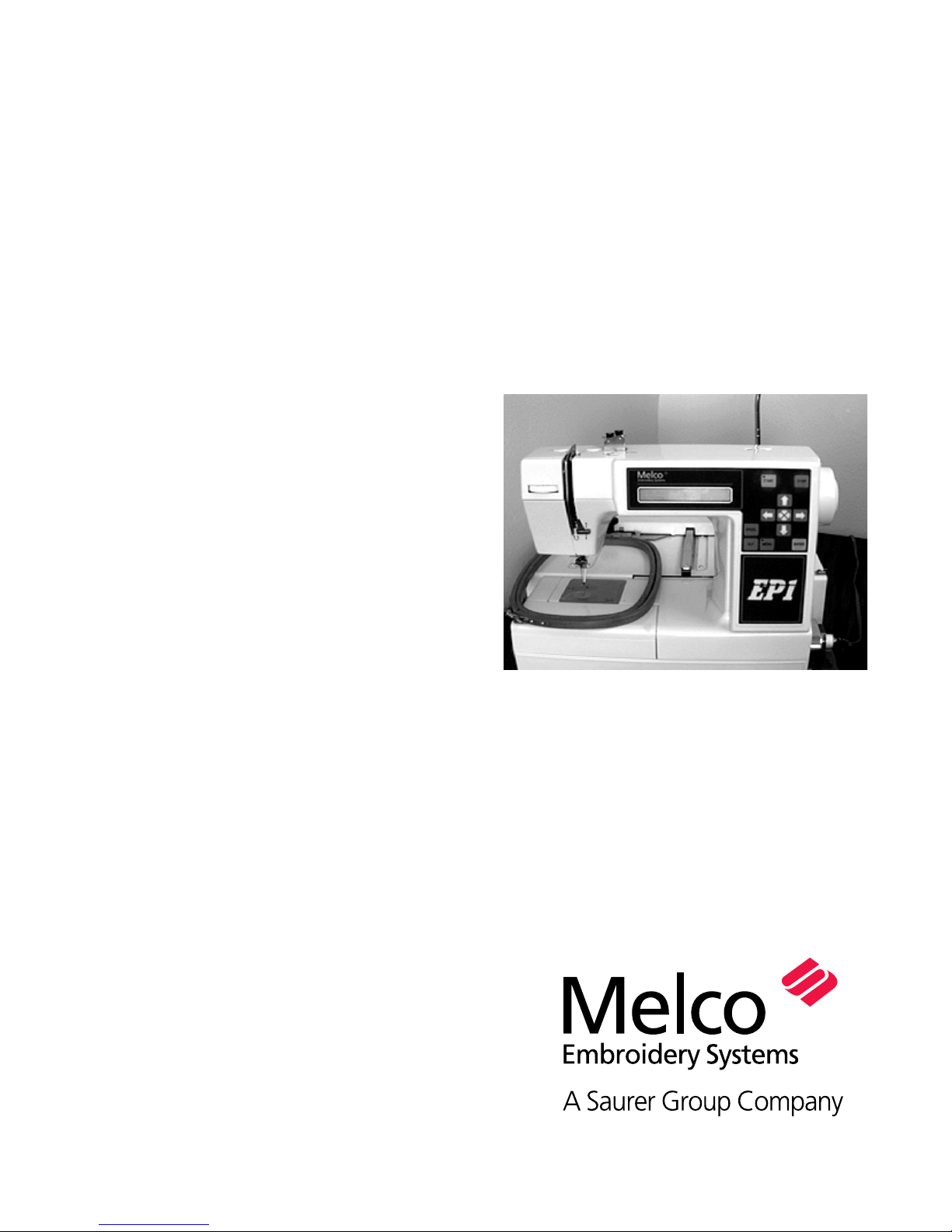
Installation, Operation, and
Maintenance manual
for the EP 1
embroidery peripheral
Part Number 11034, Revision A
• Single head, single needle
• Easy to operate
• Low power consumption
• High-quality results
Page 2

1575 West 124th Avenue
Denver, Colorado 80234
United States of America
© Copyright 1998 by Melco Embroidery Systems
ALL RIGHTS RESERVED No part of this publication may be reproduced, stored in a retrieval system,
or transmitted in any form or by any means (electronic, mechanical, photocopying, recording, or
otherwise) without prior written approval of Melco Embroidery Systems. Melco reserves the right
to revise this publication and to make changes in it at any time without obligation of Melco to
notify any person or organization of such revisions or changes.
All precautions have been taken to avoid errors or misrepresentations of facts, equipment, or
products. However, Melco does not assume any liability to any party for loss or damage caused by
errors or omissions.
Printed in the United States of America
Revision A, May 1998
Page 3

Table of Contents
Table of Contents
1. Setup
2. Needles, Bobbins, and Threads
Threading the EP1 2 - 1
Drawing Out the Bobbin Thread 2 - 3
The Bobbin Case 2 - 3
Removal 2 - 3
Winding Thread Onto The Bobbin Reel 2 - 4
Setting the Bobbin 2 - 4
Installation 2 - 5
Setting Thread Tensions 2 - 5
Upper Thread Tension 2 - 5
Bobbin Thread Tension 2 - 5
How to Select a Needle 2 - 6
Needle Replacement 2 - 6
3. Embroidery Hoops
Loading Garments 3 - 1
Round Hoops 3 - 1
Rectangular Hoops 3 - 1
Attaching The Hoop To The Pantagraph 3 - 2
4. Detailed Operation
The Control Panel 4 - 1
The Liquid Crystal Display (LCD) 4 - 1
Start Key 4 - 1
Stop Key 4 - 1
Arrow Keys 4 - 1
Hoop Center Key 4 - 1
Spool Key 4 - 1
Menu Key 4 - 1
Enter Key 4 - 1
Alt Key 4 - 2
The Light Emitting Diodes (LED) 4 - 2
The Operation Menus 4 - 2
Design Menu 4 - 2
i
Page 4

Table of Contents
Run Design 4 - 2
Frame Menu 4 - 3
Trace Menu 4 - 3
Hoop Selection 4 - 3
Move Menu 4 - 3
Moving The Hoop Numerically 4 - 3
Seeing The Hoop’s Physical Location 4 - 3
Reset Menu 4 - 4
System Reset 4 - 4
Hard Reset 4 - 4
Other Functions 4 - 4
Thread Break 4 - 4
Bobbin Thread Low 4 - 4
Dust Accumulation 4 - 4
Upper Shaft Lock 4 - 4
Hoop Limits 4 - 4
5. Configuration
Unit Number 5 - 1
Display Brightness 5 - 1
Key Click Volume 5 - 2
Error Beep Volume 5 - 2
6. Operator Maintenance
Cleaning 6 - 1
Disassembling the Hook Area 6 - 1
Assembling the Hook Area 6 - 1
General Cleaning 6 - 2
Lubrication 6 - 2
Lubricating the Hook Area 6 - 2
General Lubrication 6 - 2
7. Troubleshooting Guide
ii
Page 5

Single-Head Embroidery Peripheral
EP 1 Specifications
Maximum embroidery speed
1000 stitches per minute
Number of Heads
1
Number of needles
1
Dimensions
46cm W x 36cm H x 52cm D
18" W x 14" H x 20.5" D
Weight
26kg
58 lbs
Recommended power conditioning equipment
LC 1800 Line stabilizer (available from
Accessory Resource Corporation)
Embroidering field size
24 x 14cm (9.5 x 5.5")
Compatibility
Premier, EDS-EZ, and EDS III
Intended use
The EP 1 is designed to embroider on textile
products which are placed easily in a Melco
embroidery hoop. The machine should not be
used on thick leather, wood, plastic, or other
dense material.
Shipping weight
31kg
68 lbs
Power consumption
60 W; wired for 200V to 250V 50 or 60Hz
2 fuses, 800mA Fast Blow (FB)
Noise level and test conditions
Equivalent continuous A weighted sound pressure level at 1 meter from the machine is 66db.
The peak C weighted instantaneous sound
pressure level is 71db.
The noise level was measured sewing a test
design at 600 spm.
iii
Page 6
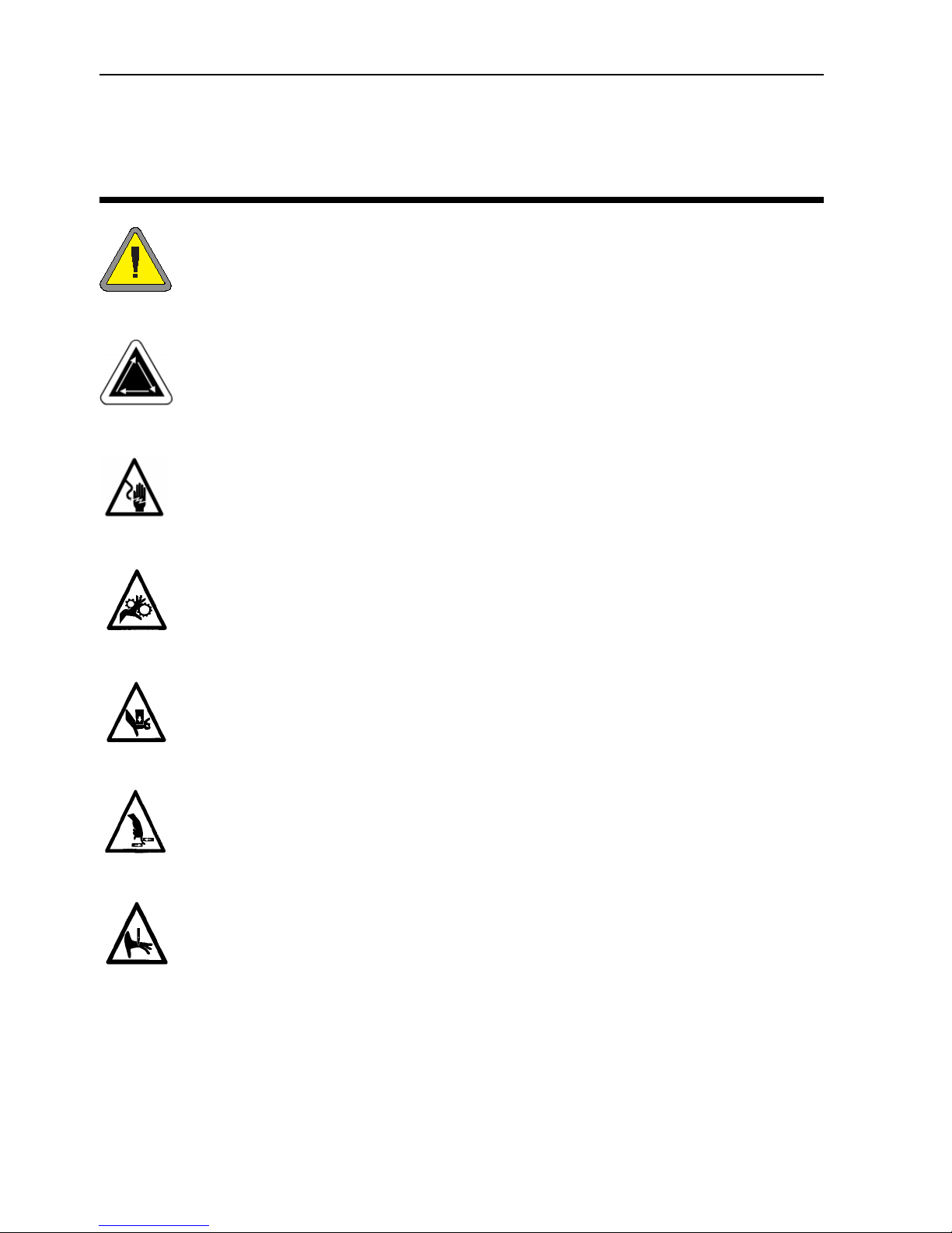
Table of Contents
Caution!
Indicates a machine component will move. Keep clear!
Shock hazard. No user replaceable parts behind this label. Do not open!
Explanation of Symbols
Pinch point, Keep clear!
Pinch point, Keep clear!
Pinch points, Keep clear!
Needle pinch point, Keep clear!
iv
Page 7
1-1
1. Setup
The setup procedure for the EP 1 Embroidery Peripheral is easy and will only take a few minutes.
1. Carefully remove the machine from the shipping container, using care not to drop or damage
any other items packed around it. The machine is heavy, so be careful. Place the machine on a
sturdy table or work bench.
NOTE: Be sure to save the shipping container and packing supplies that your embroidery periph-
eral came in. If your machine should ever require factory service, it should be returned in
the original (or other equally suitable) shipping container.
2. Make certain the machine’s power switch is turned to the OFF position.
3. Plug one end of the power cord into a wall outlet. A
surge protector is recommended but not required.
Plug the other end into the machine.
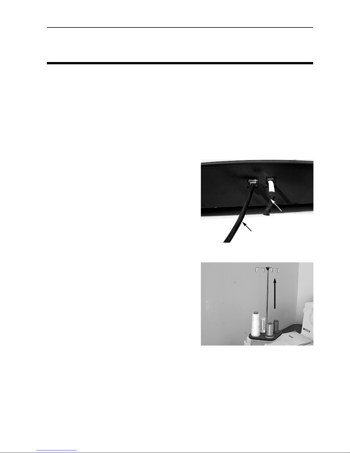
4. Connect the peripheral to your controller or host
computer using the network cable. Plug the network cable into either of the network ports, as
shown in Figure 1-1. Plug the terminator cable into
the other network connector. It does not matter
which cable is plugged into which connector.
5. Your machine may have come with a needle already
installed, but it is a good idea to start your sewing
with a new needle.
6. Locate the thread guide bar and gently pull it
upward until it reaches its maximum height. It will
extend like a car antenna. Rotate the guide bar until
the ends are aligned over the thread cones on the
base below (see Figure 1-2).
7. Your machine may have come with thread already
loaded on the bobbin, but check to make certain.
8. Load a spool of thread onto the thread stand and
thread the machine as required.
Network cable
Figure 1-1
Terminator cable
Figure 1-2
At this point your EP 1 should be ready to begin sewing.
If you should encounter any problems during this procedure, contact your local Melco representative for assistance, or call Melco’s Technical Support line.
11034 Rev. A 1. Setup
Page 8
1-2
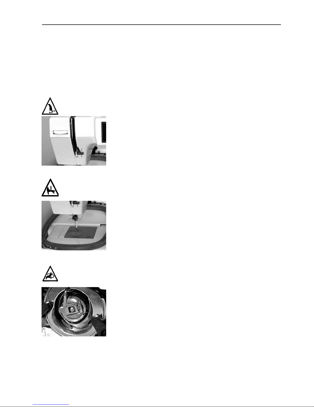
Hazards of operation
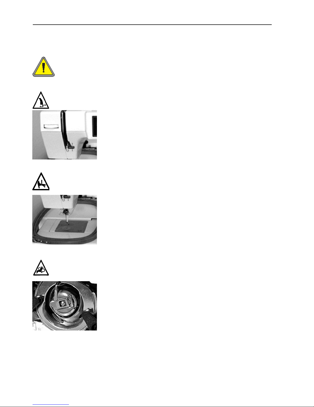
Caution! Below are risk areas or danger points encountered during operation. Always wear eye protection while operating the
machine to prevent injury in the event of a needle break. Do not
wear loose or baggy clothing when operating the machine.
Take-up Lever Oscillation
Do not touch the take-up levers during operation.
Exposed Needles During Operation
Do not place body parts or other foreign objects under the needles
during operation.
Rotary Hook Rotation
Do not attempt to change bobbin thread during operation. Do not
place hands or other objects in the rotary hook area during operation.
Do not operate the machine without the hook guards in place.
EP 1 Operation Manual Melco Embroidery Systems
Page 9
1-3
Dangers de service
Attention! Ci-dessous vous trouverez les descriptions de diverses zones
de risque ou points dangereux lors du service de la machine. Il faut toujours porter des lunettes protectrices pendant le service de la machine
afin d'éviter des blessures en cas d'une casse d'aiguille.
Oscillation du releveur de fil
Ne pas toucher les releveurs de fil pendant le service.
Aiguilles exposées pendant le service.
Ne mettre ni de parties du corps ni d'autres objets au-dessous
des aiguilles pendant le service.
Rotation de la navette rotative
Ne pas essayer de changer la canette pendant le service. Ne
pas mettre ni les mains ni d'autres objets dans la zone de la
navette rotative pendant le service. Ne pas mettre la machine
en marche sans avoir mis en place les gardes du ramasseur.
11034 Rev. A 1. Setup
Page 10

1-4
Betriebsgefahren
Vorsicht! Nachfolgend sind Risikobereiche und Gefahrenpunkte genannt,
die während des Betriebs auftreten können. Tragen Sie immer einen
Augenschutz, wenn die Maschine in Betrieb ist, um Verletzungen im Falle
eines Nadelbruchs vorzubeugen. Tragen Sie keine weite oder lockere
Kleidung, wenn Sie die Maschine bedienen.
Hin- und Herbewegung des Fadengebers
Die Fadengeber nicht berühren, wenn die Maschine in Betrieb
ist.
Offenliegende Nadeln während des Betriebs
Körperteile fernhalten und keine fremden Gegenstände unter
die Nadeln legen, wenn die Maschine in Betrieb ist.
Umdrehung des Umlaufgreifers
Die Garnspule nicht austauschen, während die Maschine in
Betrieb ist. Die Hände vom Umlaufgreifer fernhalten oder
andere Gegenstände nicht in den Bereich des Umlaufgreifers
bringen, wenn die Maschine läuft. Die Maschine nicht bedienen, wenn der Greiferschutz nicht an seinem Platz ist.
EP 1 Operation Manual Melco Embroidery Systems
Page 11
1-5
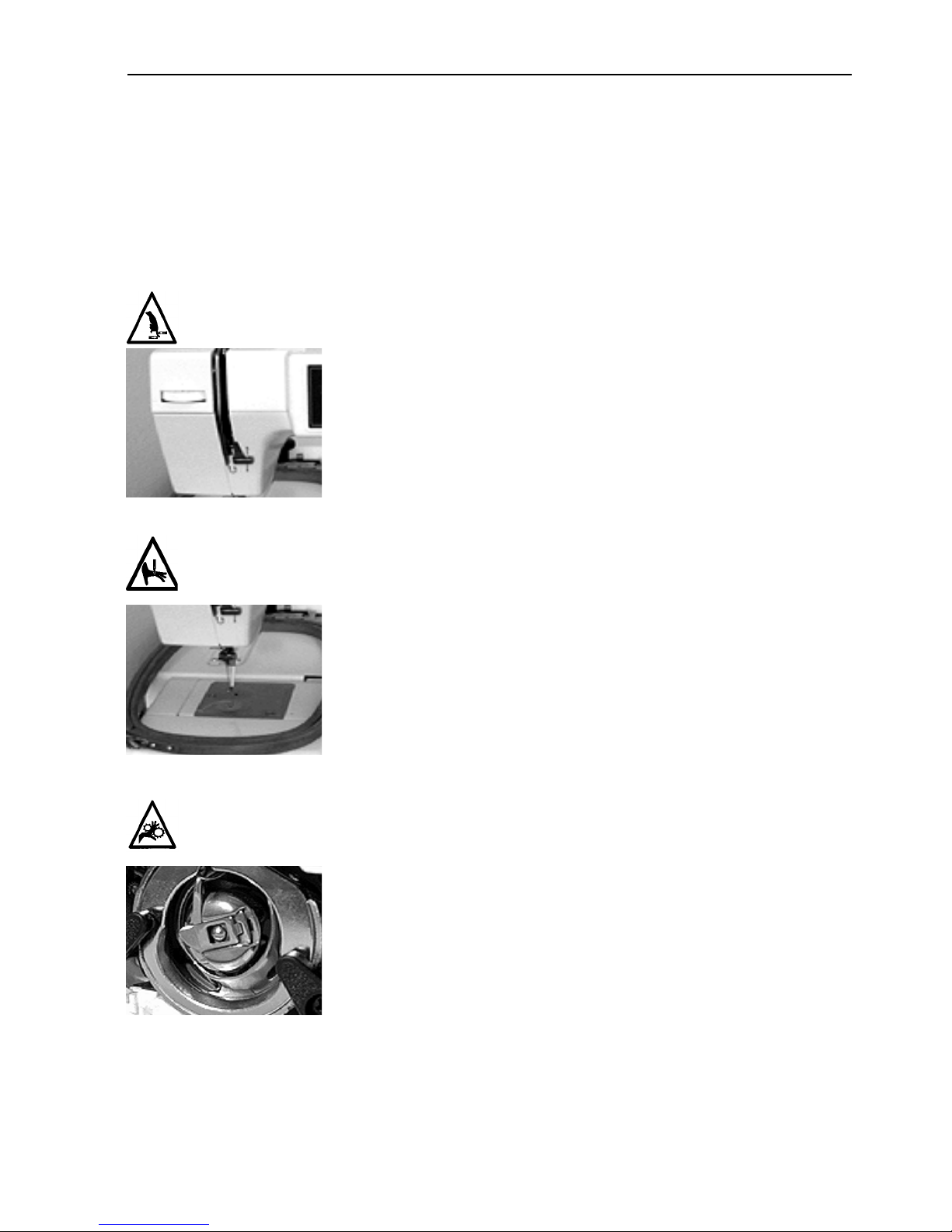
Pericoli nel funzionamento
Attenzione! Di sotto vengono descrite le zone di rischio o i punti pericolosi che potreste incontrare durante il funzionamento. Portate sempre
degli occhiali prottetivi mentre comandate la macchina, per pervenire il
ferimento in caso di rottura di ago.
Oscillazione delle leve d'avvolgimento
Non toccate le leve durante il funzionamento
Aghi esposti durante il funzionamento
Non mettete delle parti del corpo o altri oggetti stranieri sotto
gli aghi durante il funzionamento.
Rotazione del perno girevole della bobina
Non provate a ricambiare la bobina di filo durante il funzionamento. Non mettete le mani o altri oggetti sul perno girevole
della bobina durante il funzionamento.
11034 Rev. A 1. Setup
Page 12
1-6
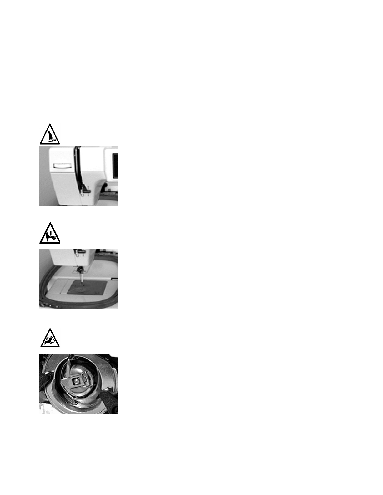
Risco de funcionamento
Atenção! São a seguir indicadas áreas de risco ou zonas perigosas encontradas durante o funcionamento. Usar sempre protecção para os olhos ao
comandar a máquina para evitar ferimentos no caso de quebra de agulhas.
Não use vestuário solto ou desapertado quando trabalhar com a máquina.
Oscilação da alavanca de enrolamento
Não toque nas alavancas de enrolamento durante o seu funcionamento.
Agulhas à vista durante o funcionamento
Não coloque partes do corpo ou objectos estranhos por baixo
das agulhas durante o funcionamento.
Rotação do gancho rotativo
Não tente mudar fios das bobinas durante o funcionamento.
Não ponha as mãos ou outros objectos na área do gancho rotativo durante o funcionamento. Não trabalhe com a máquina
sem os resguardos dos ganchos estarem instalados.
EP 1 Operation Manual Melco Embroidery Systems
Page 13
1-7
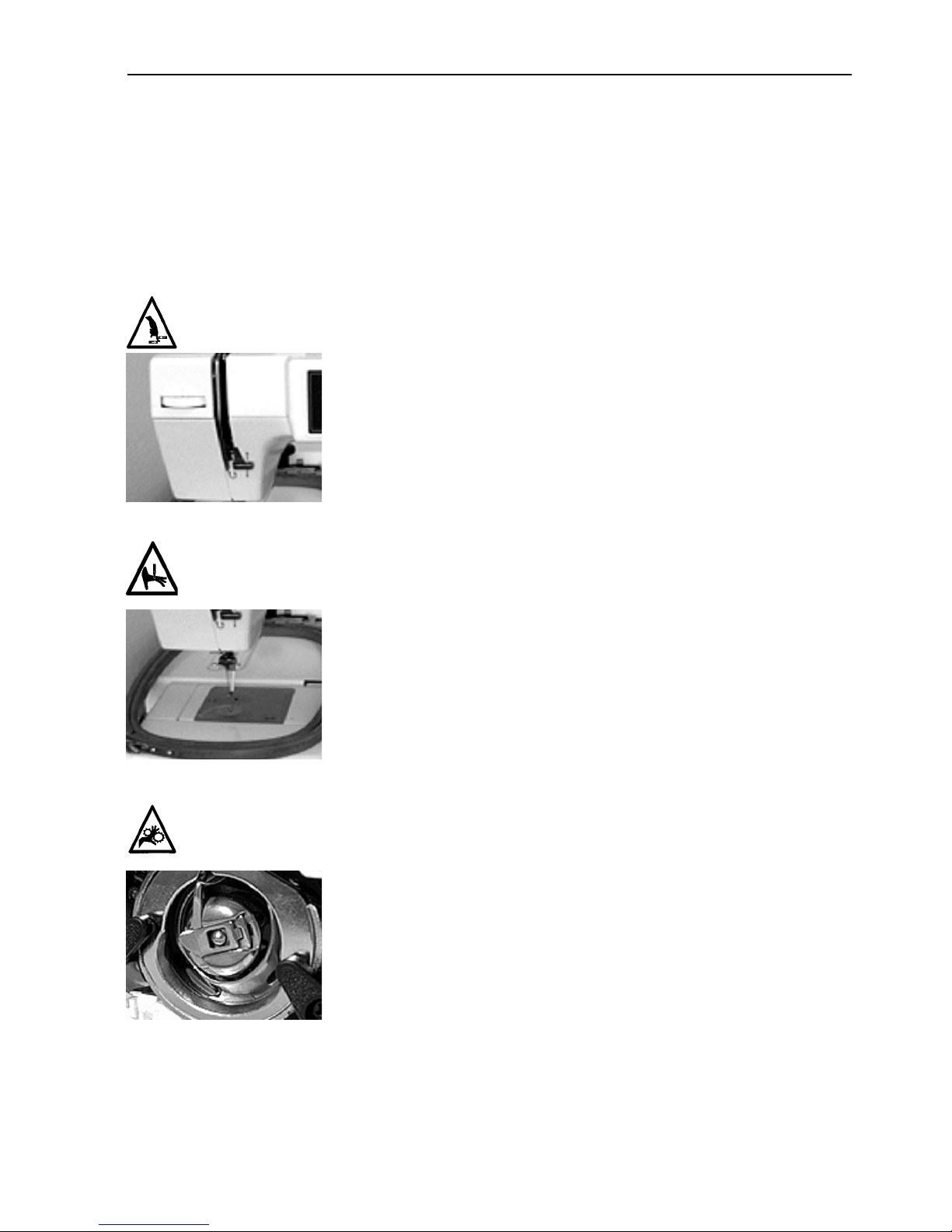
Peligros durante el funcionamiento
¡Atención! A continuación se mencionan las zonas de riesgo o los puntos
de peligro con los que se podrían encontrar Vds. durante la maniobra.
Utilicen siempre gafas protectoras cuando operen la máquina a fin de prevenir heridas en caso de rotura de la aguja. No lleven vestidos holgados
mientras están operando la máquina.
Oscilación de la palanca de compensación (entrega-hilo)
Eviten tocar las palancas de compensación (entrega-hilo)
durante el funcionamiento.
Agujas al descubierto durante el funcionamiento
Eviten colocar partes del cuerpo u otros objetos debajo de las
agujas durante el funcionamiento.
Rotación del gancho giratorio
No traten de cambiar el hilo inferior de bobina durante la
operación. Eviten colocar las manos u otros objetos en la área
del gancho giratorio durante el funcionamiento. No accionen la
máquina sin el dispositivo de protección del gancho en su sitio.
11034 Rev. A 1. Setup
Page 14

1-8
EP 1 Operation Manual Melco Embroidery Systems
Page 15
2-1
2. Needles, Bobbins, and Threads
This chapter covers how to thread your machine, select and install needles, wind the bobbin reels,
and properly set the upper and lower thread tensions.
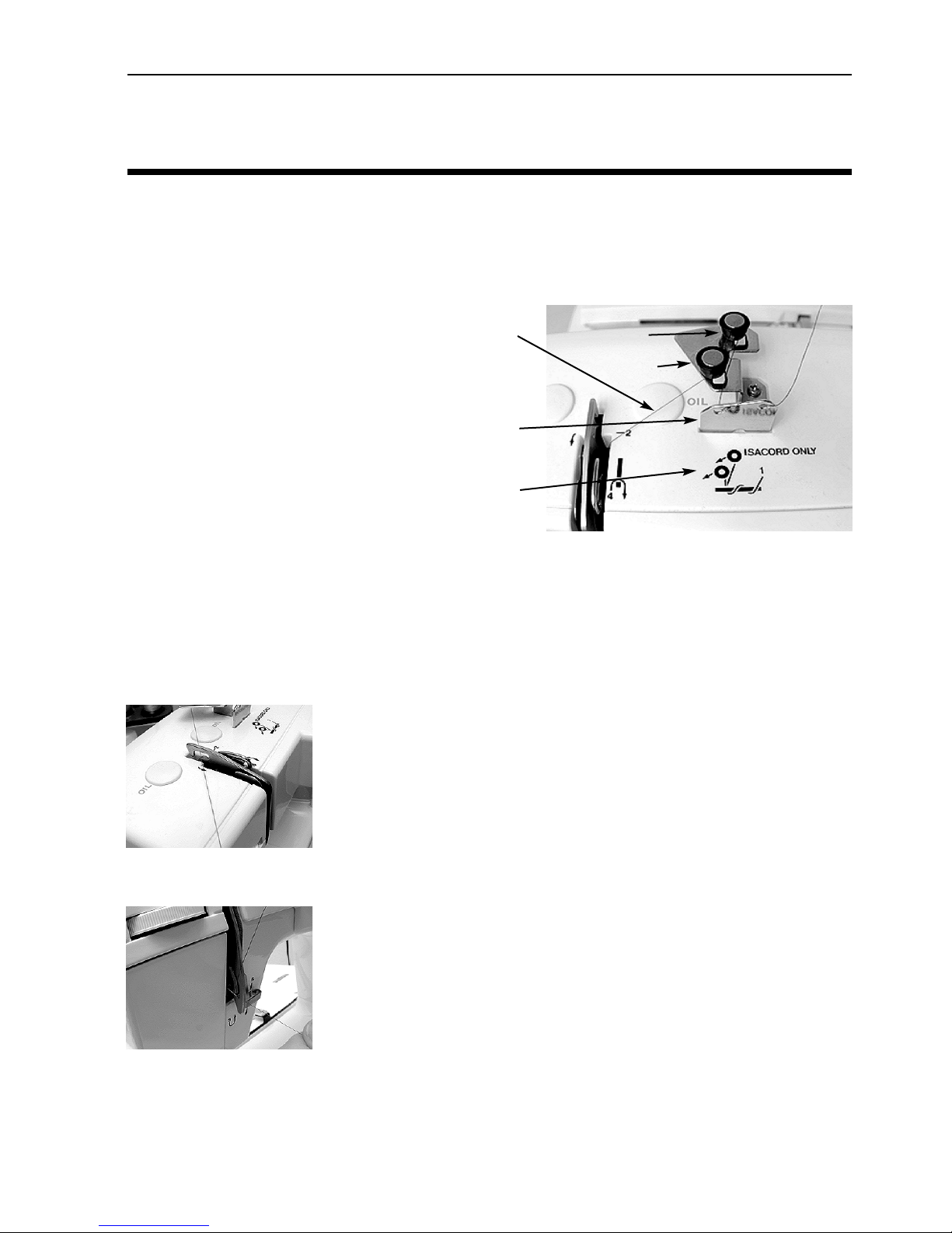
Threading the EP 1
1. When routing the thread, apply a
small amount of pressure on the
supply spool to prevent the thread
from unwinding too quickly .
2. Hook the thread onto the thread
guide mounted above the supply
spool.
3. Pass the thread into the right hole
of the top plate thread guide from
the front to the back. Bring the
thread over the top of the same
thread guide and pass it into the left hole, again from the front to the back (refer to Figure 2-
1).
4. Hook it around the back of the tension disc (A) 1/2 turn in a counter-clockwise rotation (refer
to Figure 2-1). Use the rear tension disk (B) instead of (A) only when the Isacord thread is
used.
5. Pass the thread into the rear hole of the thread tension unit, with
the thread between the thin metal piece and the bar.
Thread
Thread
guide
Threading
diagram
B
A
Figure 2-1
Figure 2-2
Figure 2-3
11034 Rev. A 2. Needles, Bobbins, and Threads
6. Pull the thread under the take-up spring and up the right side of
the thread tension unit, passing it under the take-up spring.
Page 16
2-2
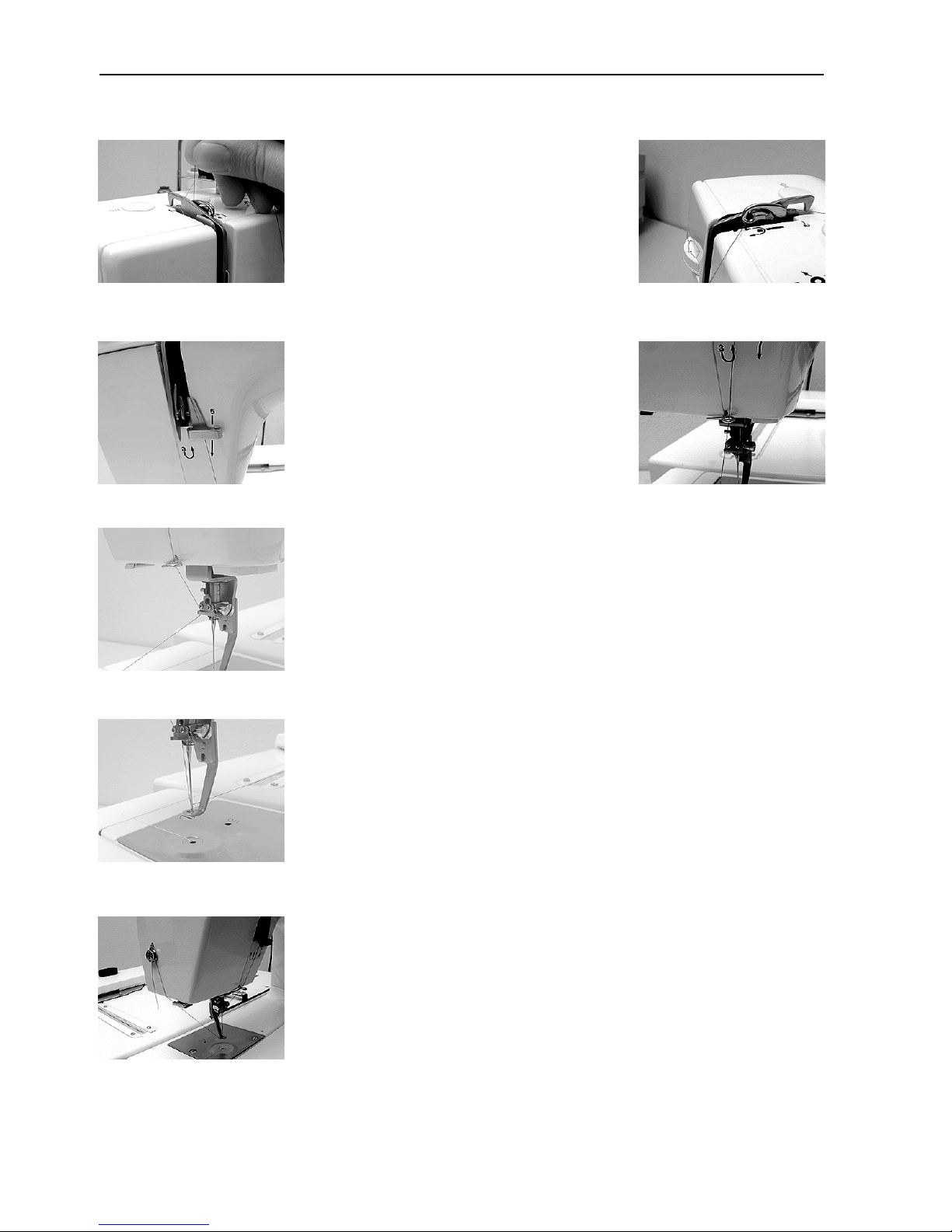
7. Pass the thread through the embroidery
thread take-up lever from the left to the
right; and then pull it downward toward
the first lower thread guide.
Figure 2-4
Figure 2-6
Figure 2-8
Figure 2-5
8. Hook the thread into the two lower
thread guides as you continue to pull it
downward.
Figure 2-7
9. Hook the thread into the needle bar thread guide from the left
side.
10. Pass the thread into the needle from the front to the rear (use a
Figure 2-9
11. After threading the needle, position the embroidery thread through
Figure 2-10
EP 1 Operation Manual Melco Embroidery Systems
threader if desired).
the presser foot hole. You may do this now by threading it as you
would the eye of a needle or in the following procedure while
drawing out the bobbin thread.
Page 17
The Bobbin Case
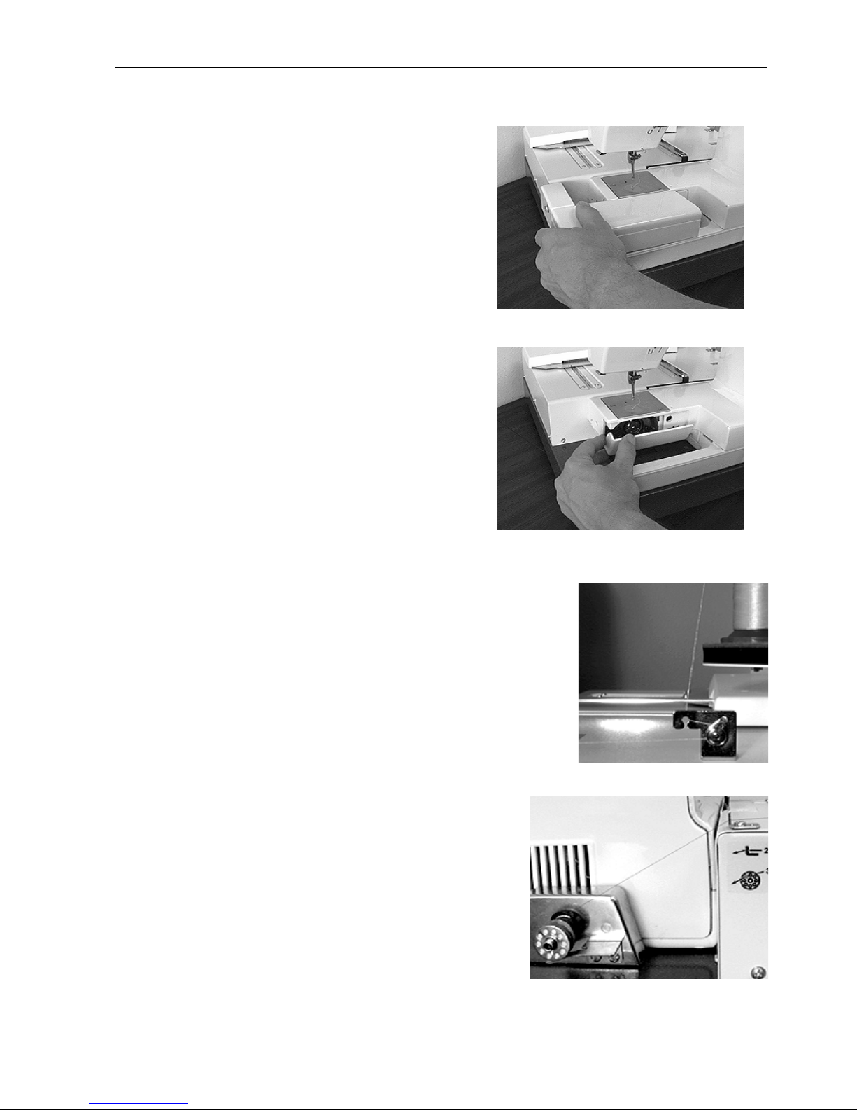
Removal
1. After turning off the power switch, lift the needle
above the throat plate by rotating the flywheel.
2. Remove the auxiliary table by lifting slightly at its
left front and sliding it off to the left.
3. Open the bed cover by placing your finger at the
left rear of the cover and flipping it forward and
down to its opened position.
4. Pull out the bobbin case lever and remove the
bobbin case from
2-3
Figure 2-11
NOTE: The hook area must be kept clean to avoid
thread breakage problems! If you find any
thread debris at this time, clean it out.
Winding Thread Onto The Bobbin Reel
The bobbin winder can wind bobbin thread anytime, even while
embroidering, because the bobbin winder is an independent part of
the embroidery machine.
1. Attach the bobbin reel onto the bobbin winding shaft, and push
the bobbin winding shaft downward.
2. After hooking the bobbin thread onto the thread guide above the
bobbin thread cone, route the thread through the first thread
guide, and then the second guide, in this order. Each thread
guide features a thread path diagram, as shown in Figures 2-13
and 2-14.
3. Pass the thread through a bobbin reel hole from the inside
of the wall to the outside.
4. Press and hold the [SPOOL] key until the bobbin begins
turning.
Figure 2-12
Figure 2-13
NOTE: If the [SPOOL] key is not held down long enough, the
bobbin will not turn.
11034 Rev. A 2. Needles, Bobbins, and Threads
Figure 2-14
Page 18
2-4
5. After the thread has been wound completely, the bobbin reel will continue to spin for a few
moments before stopping.
6. After the bobbin reel has stopped turning, cut the thread and remove the bobbin reel from
the bobbin winding shaft.
7. If the thread was cut or if thread cannot be wound on the bobbin reel normally during thread
winding, the thread winding can be stopped by pressing the [SPOOL] key again.
Setting the Bobbin
After thread has been wound onto the bobbin reel and the bobbin reel is placed into the bobbin
case, install the bobbin case into the hook body.
NOTE: Turn the power switch OFF when putting the bobbin case into the hook body.
1. Hold the bobbin case in your left hand so the open side is facing toward you.
2. Hold the bobbin reel in your right hand.
NOTE: It is recommended that you orient the bobbin reel so the thread is coming off in a clock-
wise direction. However, some users feel that orienting it with the thread coming off in a
counter-clockwise direction is better. Either way is acceptable.
3. Place the bobbin reel into the bobbin case.
4. Grasp the end of the thread, and pass the thread into the bobbin case slit.
5. Draw the thread under the tension plate and out the opening in the bobbin case, then pass
the thread into the hole of the bobbin case horn (use the aid of the threader if desired).
6. Draw out the thread about 4 inches (10cm).
7. Set the bobbin thread tension.
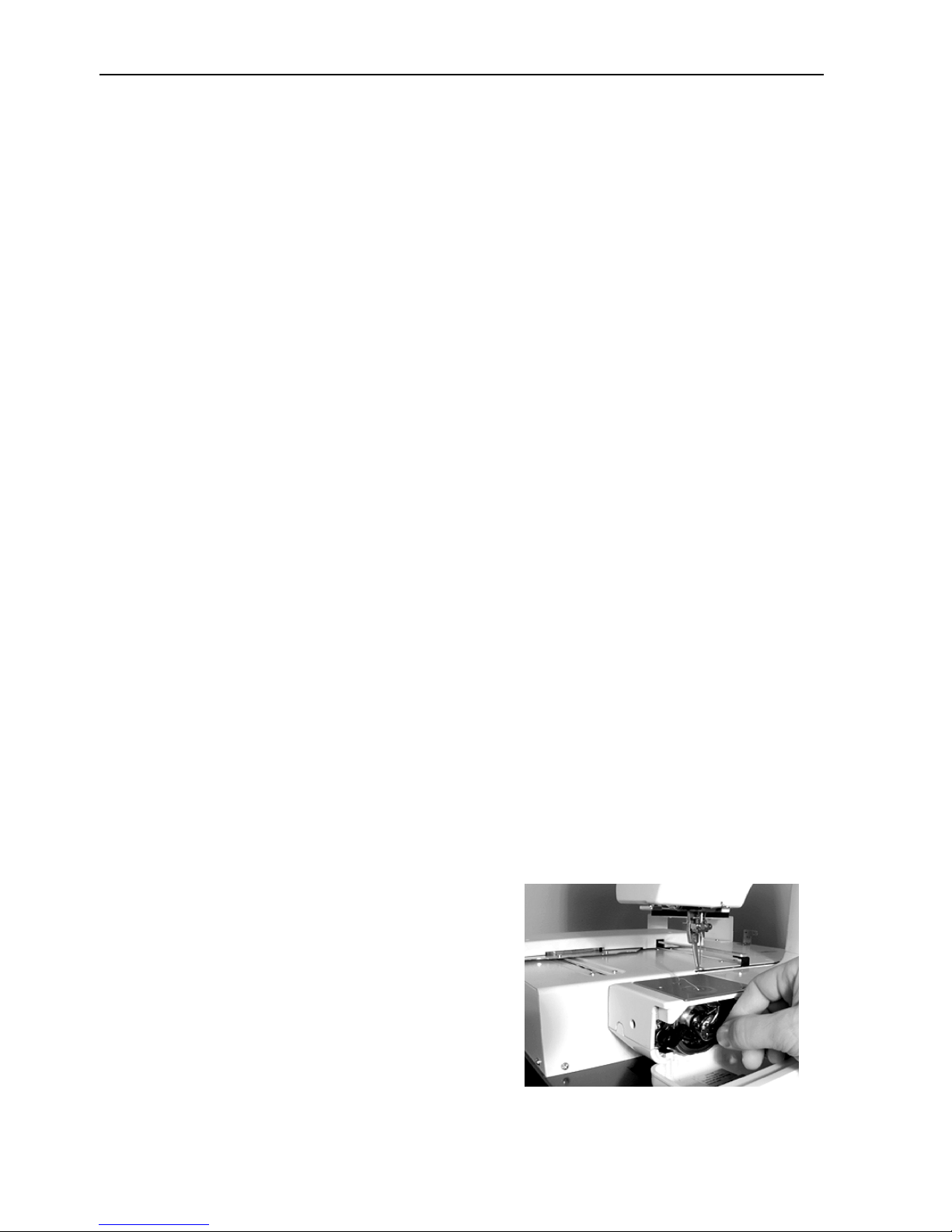
Installation
1. To install the bobbin case into the hook body, pull out the bobbin case lever as you do when
you remove the bobbin case (the bobbin does not
fall out of the case when the lever is held out).
2. Position the bobbin case horn so it points
upward. Set the horn into the concave portion of
the hook body as you insert the bobbin case onto
the post in the middle of the hook body.
3. Release the bobbin case lever and check that the
lever has grasped the end of the post, thus securing the bobbin case in the hook body.
EP 1 Operation Manual Melco Embroidery Systems
Figure 2-15
Page 19

2-5
Drawing Out the Bobbin Thread
After setting the bobbin thread and threading the embroidery thread, draw the bobbin thread out
of the needle plate hole as follows:
1. Hold the end of the embroidery thread by the left hand. Do not stretch it so tightly that the
needle tip is deflected.
2. Lower the needle once, and lift it again by rotating the flywheel toward you (counterclock-
wise) with your right hand.
3. After the embroidery thread take-up lever has reached the top, pull slightly on the embroidery
thread, and the bobbin thread will come through the needle plate hole.
4. Pull the drawn bobbin thread to the left, and hook it to the thread holder of the auxiliary
table.
5. Pull the embroidery thread loop to the left from below the Presser Foot, thus allowing it to
pass through the bottom hole.
6. Hook the embroidery thread to the thread holder on the left side of the faceplate. Take up any
looseness, and hang it down about 1 1/4 inches (3cm).
7. Use the face plate thread cutter to cut any surplus thread to a suitable length.Setting Thread
Tensions
Setting Thread Tensions
Upper Thread Tension
The upper thread tension wheel works best when set between 4 and 5 on the numbered dial. A
higher number on the dial will increase the tension and a lower number will decrease the tension.
Experimentation with different threads and fabrics will give you experience on how to set the
upper thread tension to best suit your needs.
Bobbin Thread Tension
For the best possible results, it is important to use the bobbin reels and bobbin thread that was
furnished with your machine. Most pre-wound bobbins do not work well with the EP 1. Melco
recommends the use of Rasant bobbin thread, which is available from Accessory Resource
Corporation.
1. Put the filled bobbin reel into the bobbin case. Make certain the thread goes through the slit
in the side of the case and under the tension plate.
2. Support the bobbin case with one hand and lift the thread with the other hand.
3. Dangle the case by the thread. The tension should be tight enough that the case is supported
by the thread. If the thread unwinds from the reel too easily, the tension must be increased.
Tighten the setscrew (clockwise) on the outside of the case.
11034 Rev. A 2. Needles, Bobbins, and Threads
Page 20

2-6
4. Gently jiggle the case like a yo-yo. The tension should be loose enough that a small amount of
thread (about an inch) unwinds from the reel, then stops. If no thread comes out, the tension
must be decreased. Loosen the setscrew slightly (counter-clockwise), then jiggle the case
again.
5. Once the tension has been set properly, put the thread through the hole in the horn that is
attached to the bobbin case, then install the case into the machine.
How to Select a Needle
The EP 1 embroidery machine uses a Class 15 household sewing machine needle. The following
needle types are given to help guide you in selecting the proper needle for your various embroidering situations. This is only a suggestion, and you should choose your needles in the future
through experience you gain while embroidering.
HA x 1 65/9 sharp: for embroidering a thin material, like a pocket in the lining of a coat.
HA x 1 75/11 sharp: standard, applicable to almost all embroidering.
HA x 1 90/14 sharp: for embroidering a thick material, like a canvas bag.
65/9 ball point, 75/11 ball point, & 90/14 ball point: for knits, sweaters, & other delicate garments.
Needle Replacement
1. With the power switch turned OFF, raise the needle above the needle plate by turning the flywheel counter-clockwise.
2. Loosen the needle clamp screw with a screwdriver.
3. Remove the needle by pulling it down and out of the needle clamp.
4. Check the new needle for a flat portion on the shank. If there is a flat, rotate the needle so
the flat is facing to the rear of the machine. This automatically positions the needle properly
for installation. If no flat is on the shank of the new needle you must orient the needle with
the “scarf’ facing to the rear of the machine. This will leave the ”thread groove" of the needle
in the front. (You can easily feel the groove by rubbing your finger nail across the front of the
needle.)
5. Insert the new needle fully into the needle clamp until it touches the pin.
6. Tighten the needle clamp screw securely.
EP 1 Operation Manual Melco Embroidery Systems
Page 21

3-1
3. Embroidery Hoops
Loading Garments
Do not load garments or fabrics while the hoop is attached to the EP 1. Doing so may damage
the machine. Hooping is best accomplished on a clean, sturdy table.
Round Hoops
1. Place the outer frame on a flat surface with the label on the mounting plate facing up.
2. Lay the garment over the outer frame of the hoop and center the work area.
3. Put the inner frame over the garment and press downward, capturing the garment between
the two hoops.
4. Pull the edges of the garment outward to stretch it tautly.
NOTE: Many fabrics will stretch unevenly and cause distorted embroidery if care is not used dur-
ing hooping.
5. Tighten the adjusting screw to secure the outer frame. This will not tighten the garment, only
the frame itself.
You may need to load some garments several times until you get it “just right.”
Rectangular Hoops
When stitching large embroidery designs (maximum of 5.5" x 9.4"), use the rectangular embroidery hoop (available from Accessory Resource Corporation).
Put a fabric on the embroidery hoop after placing the embroidery hoop on a table or a flat surface. Fix the four sides by inserting the fabric holders from the top. To hoop the fabric correctly,
check the fabric position after mounting the right-hand fabric holder. When mounting the lefthand fabric holder, press the fabric with the palm before mounting, and the fabric should not
stretch excessively.
11034 Rev. A 3. Embroidery Hoops
Page 22
3-2
Attaching The Hoop To The Pantagraph
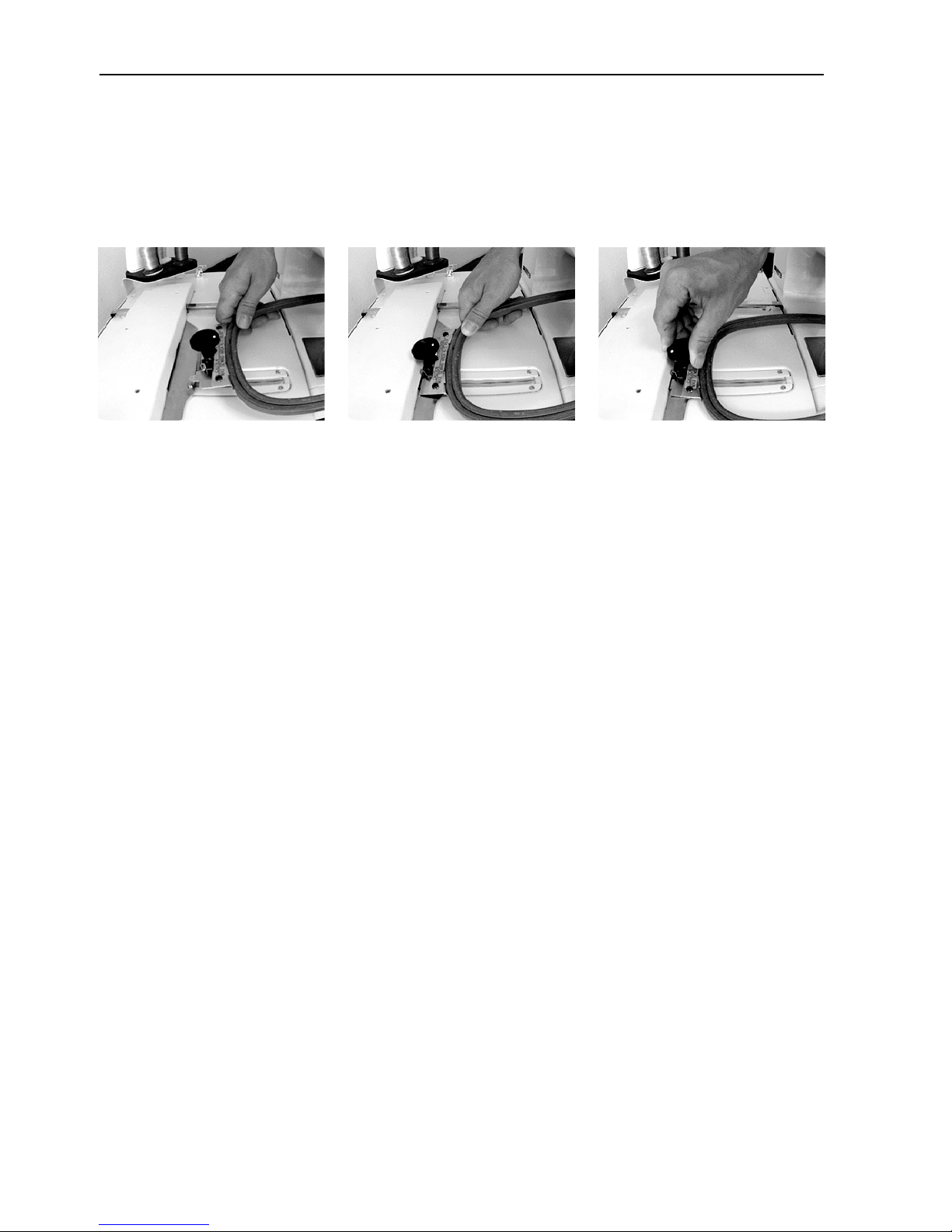
1. Hold the hoop at a slight angle (approximately 15 degrees) and slide the mounting plate into
the pantagraph opening, as shown in Figure 3-1.
Figure 3-1 Figure 3-2 Figure 3-3
2. Lower the hoop, with the mounting plate centered over the two guide pins, as shown in
Figure 3-2.
4. When the mounting plate is firmly placed on the guide pins, turn the mounting knob clockwise to secure the hoop, as shown in Figure 3-3.
To remove the rectangular embroidery hoop, turn the knob in the direction opposite the arrow
then remove the mounting plate from the guide pins.
NOTE: When removing a fabric from a rectangular hoop, press the fabric holder from the rear
side (lower face) of the hoop, and the fabric can be removed easily.
EP 1 Operation Manual Melco Embroidery Systems
Page 23

3-3
After sending a design to the EP 1, follow the steps below:
1. Press [MENU] until the display reads DESIGN MENU.
2. Press [ENTER] to display the design. Select from the available designs by using the [ò] or [ñ]
keys.
3. Press [ENTER] again to select the design in the display. The display will then read RUN DESIGN.
4. Press [ENTER] once again to set the design queue.
5. Press [MENU] until the display reads TRACE MENU.
6. Press [ENTER]. The display will read CENTERING OFF.
7. Press the [ò] key. The display will read TRACE OUTLINE. Press [ENTER] to calculate the trace
area. The display will read TRACE DESIGN.
8. Press [START] to trace the design.
If the hoop needs to be moved for embroidery, use the appropriate arrow keys, then press [START]
to trace the design again.
9. Press [ENTER] to prepare the EP 1 for embroidery.
10. Press [START] two times.
11. When the design is finished embroidering, the display reads END OF DESIGN. Press [START] to
embroider this design again, or press [MENU] until the display reads RESET MENU to change
designs.
12. Press [ENTER] four times (until the display reads MACHINE 01 READY.
13. Repeat procedure for the next design.
NOTE: If you lose your place during this sequence, go to the RESET MENU and press [ENTER] four
times. It is easier to reset and start again than to back out of an error.
11034 Rev. A 3. Embroidery Hoops
Page 24

3-4
EP 1 Operation Manual Melco Embroidery Systems
Page 25
4. Detailed Operation
This chapter explains all the control panel keys and the various operation menus of the EP 1
embroidery peripheral.
The Control Panel
The Liquid Crystal Display (LCD)
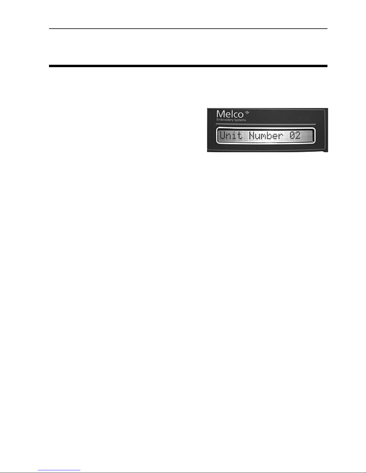
Displays the different menus and choices, as well as
embroidering and design information (see Figure 4-1).
Figure 4-1
Start Key
Begins the embroidery process and restarts it if the machine was stopped. Also activates the
Return to Origin, Trace Outline, and Move operations.
4-1
Stop Key
Halts the embroidering process. Also activates the Frame Back function. Press once and release
and the machine will “back up” one stitch. Press and hold for 5 seconds and the machine will
back up continuously, even after the key is released, until [STOP] is pressed again.
Arrow Keys
The arrow keys allow you to move the hoop and manually select the starting position for embroidery. Also used to move through the various operation menus.
Hoop Center Key
Pressing this key centers the chosen hoop directly beneath the needle.
Spool Key
Activates the bobbin winding mechanism, and manually stops winding.
Menu Key
Selects the different operation menus. Each time [MENU] is pressed the next menu will be shown
on the display. After the last menu has been displayed, the first will be shown again
11034 Rev. A 4. Detailed Operation
Page 26

4-2
Enter Key
Used to choose different menu options and to display design information during embroidery. Press
once during embroidery and the stitch count and preset maximum embroidery speed are displayed. Press again during embroidering and the design name and present embroidery speed are
displayed.
Alt Key
This key is used only in conjunction with other keys to activate the following options:
[ALT] + [ñ] increases the preset maximum embroidery speed while embroidering.
[ALT] + [ò] decreases the preset maximum embroidery speed while embroidering, deletes design
files in the Design menu, and allows you to change the machine’s unit number during a hard
reset.
[ALT] + [ï] allows you to see the width of a chosen design from the centerpoint.
[ALT] + [ð] allows you to see the height of a chosen design from the centerpoint.
[ALT] + [MENU] allows you to move through the operation menus in reverse order.
[ALT] + [ENTER] enables you to “undo” your current menu choice and return to the idle mode display.
The Light Emitting Diodes (LED)
Two of the control keys, Start and Menu, feature a small red LED in the upper left corner.
The Menu LED will glow to indicate a menu operation in progress.
The Start LED will glow while the machine is embroidering. If the embroidering is stopped (either
manually or due to a thread break) the LED will blink continuously.
The Operation Menus
Design Menu
Press [MENU] until the display reads DESIGN MENU, then press [ENTER]. You can use the [ñ] or
[ò] keys to scroll through up to 16 different designs sent from the controller computer. If no
designs are present, the display will read NO DESIGNS FOUND.
To select a design that is displayed, press [ENTER]. To delete a design that is displayed, press [ALT]
+ [ò], then press [ñ] for “yes” or [ò] for “no”. If the design is sent from the controller computer
using the Auto Delete feature, it will automatically be deleted at the end of embroidering.
EP 1 Operation Manual Melco Embroidery Systems
Page 27

4-3
Run Design
Press [MENU] until the display reads RUN DESIGN, then press [ENTER]. The display will read SET
QUEUE 01, then will display your chosen file name. Up to 28 queue settings may be assigned and
their designs embroidered one after another. Once a file has been embroidered, it will be removed
from the queue if the auto delete feature is activated and the next file in the queue will be selected. If the design is sent from the controller computer using the Auto Run feature, it will automatically be added to the queue.
NOTE: If you are embroidering one design at a time, always make certain the display reads:
QUEUE 01. This ensures you are always embroidering the “current” design and not a
“previous” one.
Frame Menu
Press [MENU] until the display reads FRAME MENU, then press [ENTER]. The display will read
FRAME BACK. Press [ð] and the display will read FRAME FORWARD.
Press [STOP] once and release, and the machine will “back up” or “move forward” one stitch.
Press and hold for 5 seconds and the machine will frame backward or forward continuously, even
after the key is released, until [STOP] is pressed again. This operation will stop automatically at the
origin, end point, or next color change.
Press [ò] and the display will read RETURN TO ORIGIN. Press [ENTER] and the display will read:
FRAME FORWARD. Press [START] and the hoop will move to the point of origin for the last design
sewn.
Trace Menu
Press [MENU] until the display reads TRACE MENU, then press [ENTER]. The display will read CENTERING OFF. Press [ð] and the display will read CENTERING ON. Press [ENTER] and the display will
read CALCULATING. Once the design outline has been calculated, the display will read TRACE
OUTLINE. Press [ENTER] and the display reads TRACE FILE1. Press [START] and the hoop will move
beneath the needle to trace the outline of the selected design.
If the outline of the design is larger than the hoop, the alarm will sound and the display will read
FRAME OVER. If no design was selected, the alarm will sound and the display will read RUN JOB
ERROR.
Hoop Selection
Press [MENU] until the display reads HOOP SELECTION, then press [ENTER]. You are offered four
different hoop choices. Press [ñ] or [ò] to select a hoop type and size, then press [ENTER]. The
chosen hoop will remain selected even after the power has been turned off.
NOTE: Hoop sizes cannot be changed during embroidering.
11034 Rev. A 4. Detailed Operation
Page 28
4-4
Move Menu
Moving The Hoop Numerically
Press [MENU] until the display reads MOVE MENU, then press [ENTER]. The display will read X, Y
MOVE. Press [ENTER] again and the display will read X+00.00 Y+00.00. Move the cursor to the
area you want to change by pressing [ï] or [ð]. Change the coordinates by pressing [ñ] or [ò]
until the desired number has been reached. Press [START] and the hoop will move to the new
location.
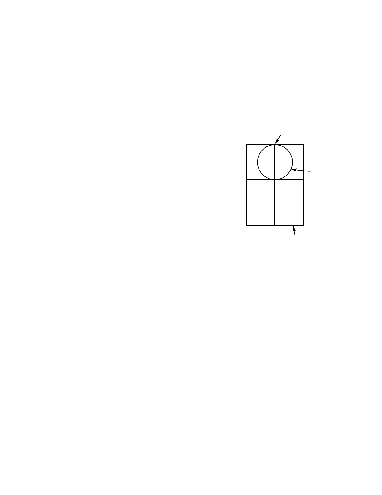
Mounting point
Seeing The Hoop’s Physical Location
Press [MENU] until the display reads MOVE MENU, then press
[ENTER]. The display will read X, Y MOVE. Press [ò] and the
display will read LOCATION. Press [ENTER] and the display will
show the X and Y coordinates of the selected hoop based on
the total embroidery area available to the EP 1.
Figure 4-2 shows an example of this. The X,Y location of any
design is based on the total embroidery area of the EP 1,
with the reference point being the lower-left corner of that
area. The total embroidery area is 5.5" wide by 9.4" high, so
all location measurements are based on that size.
0,0
Reset Menu
System Reset
Press [MENU] until the display reads RESET MENU, then press [ENTER]. The display will read SYSTEM RESET. Press [ENTER] and the display will read ** RESET **. All of the designs in the embroidery queue will be cleared but not deleted from memory.
Hard Reset
Press [MENU] until the display reads RESET MENU, then press [ENTER]. The display will read SYSTEM RESET. Press [ñ] or [ò] and the display will read HARD RESET. Press [ENTER] and the display
will read ** RESET **, followed by MEMORY CLEARED. All of the changes that you have made
since the machine was turned on will be reset.
Y
Current
hoop
X
Sewing field
Figure 4-2
Other Functions
Thread Break
If the upper thread should break while embroidering, the EP 1 will stop embroidering, the alarm
buzzer will sound, and the display will read THREAD BROKEN.
EP 1 Operation Manual Melco Embroidery Systems
Page 29

4-5
Bobbin Thread Low
If the bobbin thread runs low, the alarm will sound and the display will read BOBBIN THREAD.
Dust Accumulation
If excessive dust accumulates inside the bobbin case, the alarm will sound and the display will
read DUST! KEEP CLEAN.
Upper Shaft Lock
If the upper shaft stops moving and locks up due to excessive thread build-up in the bobbin case,
the alarm will sound and the display will read REMOVE THE LOCK! Clear the lock.
Hoop Limits
If your selected design is too large for the current hoop, there is a chance the hoop will move
beneath the needle during embroidering, which will damage the needle, hoop, and possibly the
drive mechanism. Using the Trace option prior to embroidering eliminates the chance of this
occurring. However, if the hoop limits are exceeded, the alarm will sound and the display will read
RACK LIMIT.
11034 Rev. A 4. Detailed Operation
Page 30

4-6
EP 1 Operation Manual Melco Embroidery Systems
Page 31

5-1
5. Configuration
The EP 1 allows you the option of setting the unit number, display brightness, and volume of the
key clicks and error beeps.
Unit Number
If you have several embroidery machines hooked up to one computer, each machine must be
assigned its own unit number. Each EP 1 is set at the factory as unit #1 but you can change that
number easily.
1. With the machine power OFF, hold down the [ALT] and [ò] keys and keep holding them down
while you turn the power ON. Once the power is on, release the keys and the display will
read: UNIT NUMBER _ _. Press [ENTER] and the display will read UNIT NUMBER 01.
2. Change the unit number by pressing the [ñ] or [ò] keys until the display shows the number
that you want.
3. Press [ENTER] until the display reads: MEMORIZE & EXIT.
4. Press [ENTER] again to “save” the unit number.
5. Turn the machine power OFF, wait a few seconds, then turn it back ON. When the machine
powers up, the display will show the new unit number.
NOTE: If the power is turned off before completing this procedure, the setting will not be saved.
Display Brightness
The LCD can be set at several different brightness levels.
1. With the machine power OFF, hold down [ALT] and the [ò] key and keep holding it down
while you turn the power ON. Once the power is on, release the key and the display will read:
UNIT NUMBER _ _. Press the [ò] key and the display will read BRIGHTNESS. Press [ENTER] and
the display will read BRIGHTNESS 50.
2. Change the display brightness by pressing the [ñ] or [ò] keys until the display is at the right
brightness setting for your particular needs.
3. Press [ENTER] until the display reads: MEMORIZE & EXIT.
4. Press [ENTER] again to “save” the brightness level.
5. Turn the machine power OFF, wait a few seconds, then turn it back ON. When the machine
powers up, the display will be at the new brightness setting.
NOTE: If the power is turned off before completing this procedure, the setting will not be saved.
11034 Rev. A 5. Configuration
Page 32

5-2
Key Click Volume
Each time you press one of the keys on the EP 1 control panel, the machine responds with a
“click” sound. You can adjust the volume of this click to suit your needs.
1. With the machine power OFF, hold down the [ALT] and [ò] keys and keep holding them down
while you turn the power ON and the display will read UNIT NUMBER _ _.
2. Press the [ò] twice and the display will read: KEY CLICK.
3. Press [ENTER] and the display will read: KEY CLICK 30.
4. Change the key click volume by pressing the [ñ] or [ò] keys until the desired volume is
obtained.
5. Press [ENTER] until the display reads: MEMORIZE & EXIT.
6. Press [ENTER] again to “save” the click volume.
7. Turn the machine power OFF, wait a few seconds, then turn it back ON. When the machine
powers up, the key click volume remains at the new level.
NOTE: If the power is turned off before completing this procedure, the setting will not be saved.
Error Beep Volume
Whenever an operation error occurs, the EP 1 beeps. The volume of this beep can be adjusted to
suit your needs.
1. With the machine power OFF, hold down the [ALT] and [ò] keys and keep holding them down
while you turn the power ON and the display will read UNIT NUMBER _ _.
2. Press the [ò] three times and the display will read: ERROR BEEP.
3. Press [ENTER] and the display will read: ERROR BEEP 30.
4. Change the error beep volume by pressing the [ñ] or [ò] keys until the desired volume is
obtained.
5. Press [ENTER] until the display reads: MEMORIZE & EXIT.
6. Press [ENTER] again to “save” the beep volume.
7. Turn the machine power OFF, wait a few seconds, then turn it back ON. When the machine
powers up, the error beep volume remains at the new level.
NOTE: If the power is turned off before completing this procedure, the setting will not be saved.
EP 1 Operation Manual Melco Embroidery Systems
Page 33
6. Operator Maintenance
This section explains how to clean and correctly lubricate your EP 1 .
Cleaning
A clean hook area is essential for proper operation.
The hook area should be checked at the start of
each day and each time bobbin thread is added.
Disassembling the Hook Area
1. Position the needle above the needle plate by
rotating the flywheel.
2. Open the bed cover and remove the bobbin
case.
6-1
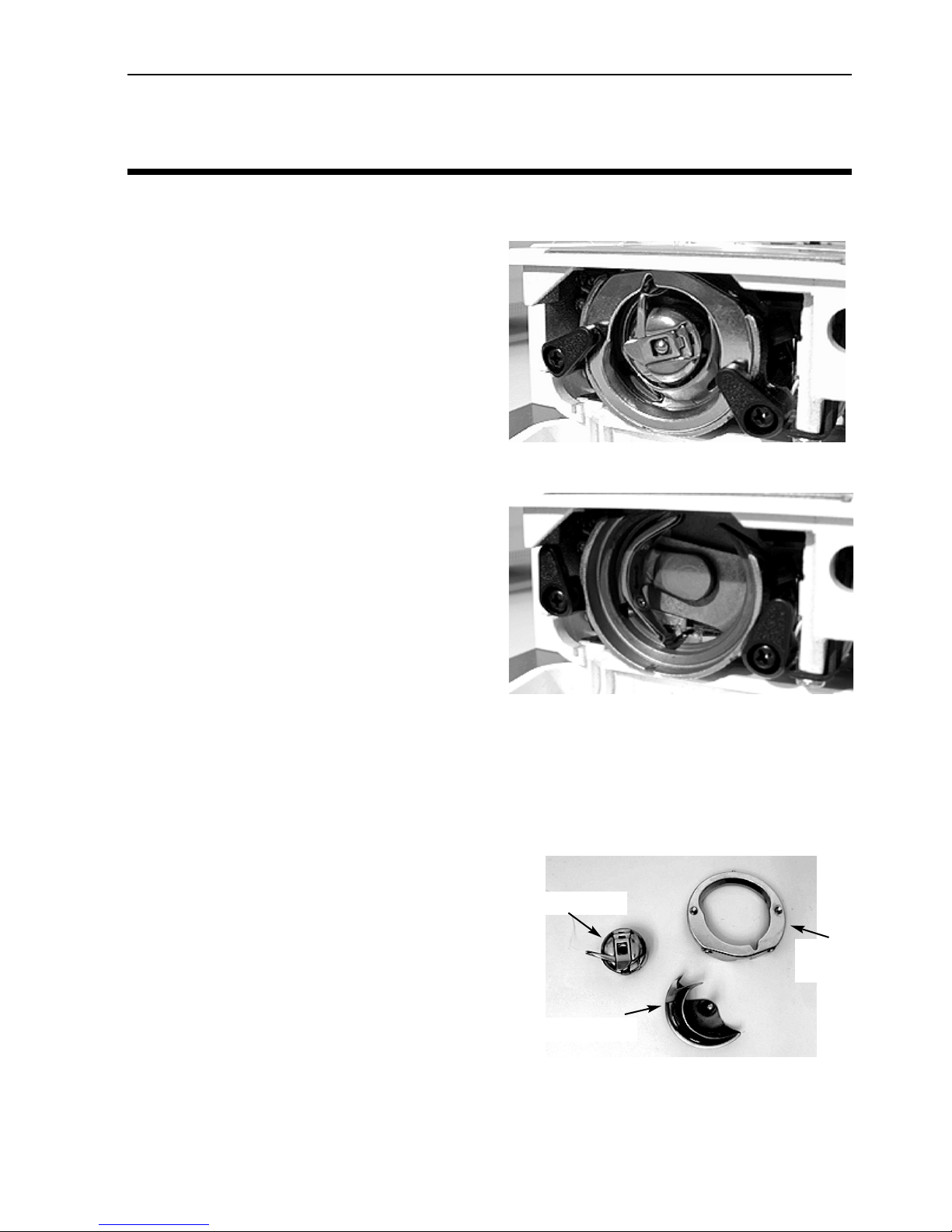
Figure 6-1
3. Open the two hook race body cover holders by
rotating the left one counterclockwise and the
right one clockwise, as shown in Figure 6-1.
4. Remove the hook race body cover.
5. Remove the rotary hook.
Clean the interior of the hook race body cover and
rotary hook body by using a brush or a soft, oily
cloth only. Remove any dust from the two bobbin
thread sensor holes inside the hook race body with a cotton swab.
NOTE: Do not use any cleaning chemicals to remove pieces of threads and dust.
Figure 6-2
Assembling the Hook Area
1. Insert the rotary hook body into the hook race
body.
2. Install the hook race body cover by fitting the
hook race body pin into the hook race body
slit.
Bobbin case
Hook race
body cover
3. Close the right and left hook race body cover
holders.
4. Install the bobbin case.
5. Close the bed cover.
11034 Rev. A 6. Operator Maintenance
Rotary hook
Figure 6-3
Page 34
6-2
General Cleaning
Cleaning the outside surfaces of the machine is not important for operation, but is an aesthetic
consideration. Do not use harsh detergents such as powdered cleansers or “all-purpose cleaners”
for the plastic or painted parts of your machine. Use mild cleaners or a mild detergent soap solution, along with a soft, clean cloth to wipe the surfaces.
Lubrication
Lubricating the Hook Area
A well lubricated hook assembly is essential for proper operation of the machine. It should be
oiled every day or each time you clean the hook assembly. Make certain that the needle is in
the"up" position.
1. Remove the rotary hook body the same way you would to clean it.
2. Wipe the inside of the hook race body and the outside of the rotary hook body with an oil
cloth. To avoid excessive lubrication, use an oil cloth only.
3. Reassemble the hook assembly.
General Lubrication
CAUTION! Stop the machine before performing any lubrication procedures.
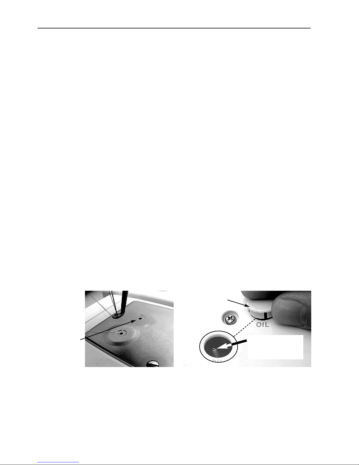
1. Place 1-2 drops of lubricating oil in the throat plate shown in Figure 6-4, once every week.
2. Lift the plastic cap and place 1-2 drops of lubricating oil in the tube shown in Figure 6-5 once
every week. Replace the plastic cap when done.
Lift this cap
1-2 drops of oil
each week in
this hole.
Figure 6-4
Figure 6-5
Place 1-2 drops of
oil into this tube
each week
EP 1 Operation Manual Melco Embroidery Systems
Page 35
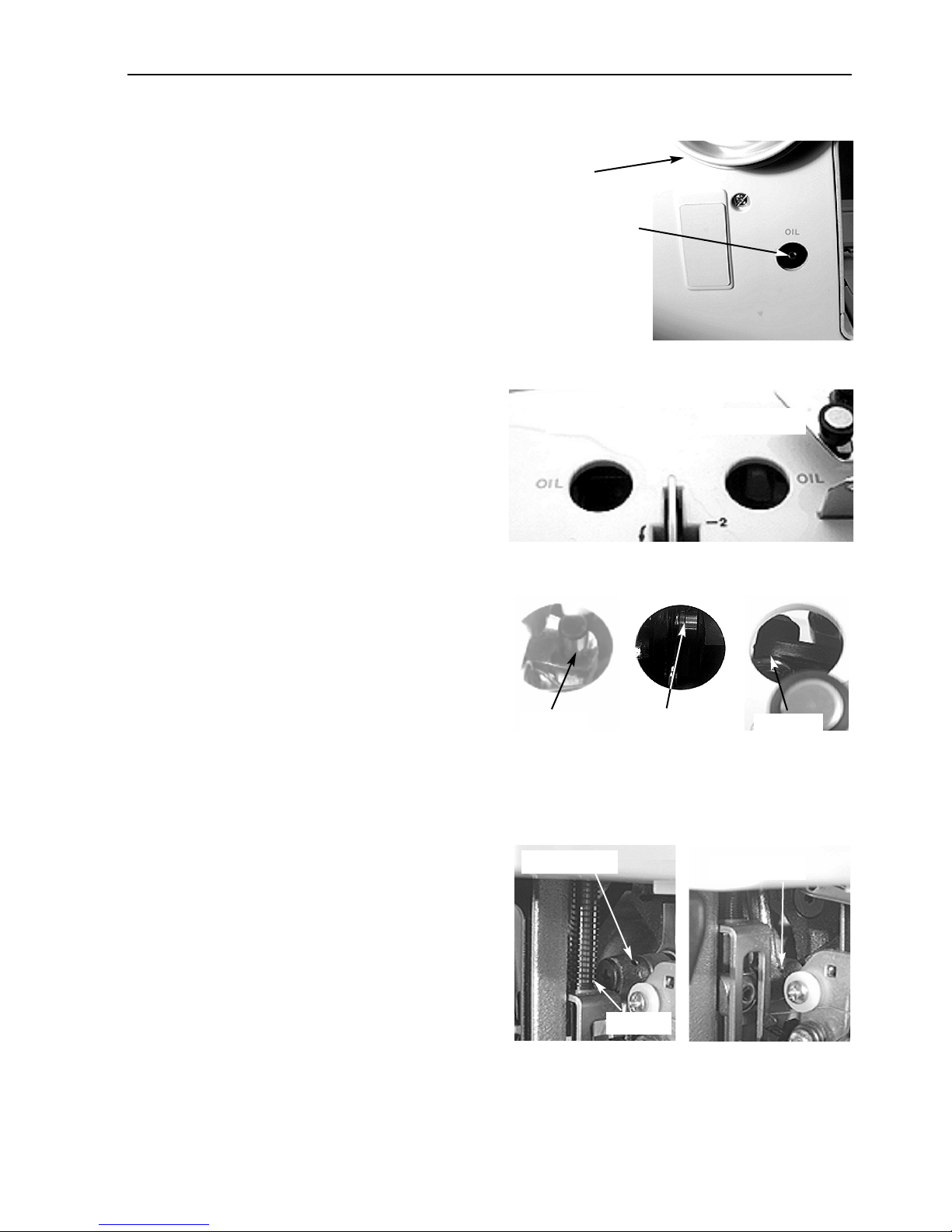
3. Below the flywheel, remove the plastic cap and
place 1-2 drops of lubricating oil in the tube
shown in Figure 6-6 once every month. Replace
the plastic cap when done.
4. Remove the plastic caps over oil holes #1 and
#2, as shown in Figure 6-7.
5. Inside oil hole #1, place 1-2 drops of oil onto
the shaft as shown in Figure 6-8, Detail “A”,
once each month.
6. Inside oil hole #2, place 1-2 drops of oil onto
the connecting arm shaft, as shown in Figure
6-8, Detail “B”, once each month. A small
flashlight will help to locate the right spot.
7. Inside oil hole #2, place 1-2 drops of oil onto
the other end of the connecting arm shaft, as
shown in Figure 6-8, Detail “C”, once each
month. Rotating the flywheel will help move
the connecting arm into the correct position.
Replace the plastic caps when done.
Flywheel
Place 1-2 drops
of oil into this
tube once each
month
Oil hole #1
6-3
Figure 6-6
Oil hole #2
Figure 6-7
8. Open the face cover. Referring to Figure 6-9,
Detail “A”, place 1-2 drops of oil in the upper
oil hole of the main connecting rod each
month. Rotating the flywheel will help move
the connecting rod into the correct position.
Also place 1-2 drops of oil at the base of the
spring each month.
9. Referring to Figure 6-9, Detail “B”, place 1-2
drops of oil in the lower oil hole of the main
connecting rod each month. Rotating the flywheel will help move the connecting rod into
the correct position.
Oil here Oil here
Detail A
Detail B
Figure 6-8
Upper hole
Spring
Detail A
Oil here
Detail C
Lower hole
Detail B
11034 Rev. A 6. Operator Maintenance
Figure 6-9
Page 36
6-4
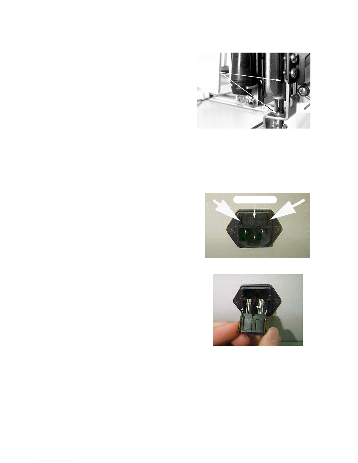
10. Place 1-2 drops of oil at both locations
where the shaft passes through a bushing, as
shown in Figure 6-10, once each month.
Close the face cover when done.
11. After lubrication, the fabric and thread during the next embroidery operation may
become contaminated with oil. To keep from
contaminating actual garments, sew on a
scrap piece of fabric for a short time before
continuing.
NOTE: Never use any oil other than the sewing machine oil recommended by Melco (one contain-
er of oil is included with the machine).
1-2 drops of
oil at each
location.
Figure 6-10
Replacement Parts
Fuses
There are two operator-replaceable fuses. 2 spare fuses are
included with your machine. To replace a fuse, follow these
steps:
Plastic cover
1. Turn off the power and disconnect the power cord.
2. Directly above where the power cord plugs in is a small
plastic cover (see Figure 6-11). Use your fingernails to
unclip each side of this cover in the locations shown in
Figure 6-11.
3. When the cover is unclipped, pull on the cover to
remove the fuse holder (see Figure 6-12).
4. Change the fuse(s), then replace the fuse holder.
5. Reconnect the power cord and turn on the power.
Figure 6-11
Figure 6-12
EP 1 Operation Manual Melco Embroidery Systems
Page 37
Tool Kit
Large Slotted Screwdriver Small Slotted Screwdriver
Cleaning brush Scissors
Thread Tool
ITEM DESCRIPTION
11034 MANUAL, OPRTR, EP-1
007134-06 THD METALLIC GOLD
007135-01 THD METALLIC SILVER
764121-01 THD RASANT 150, WHITE CONE
353233-01 BOX, KIT, ACCESS, STELLAR
005911-01 HOOP, ASSY, PREMIER 9X5
011359-01 KIT, POLY, SOFT, 20 CONE
790000-88 POLY-SOFT COLOR CHART
763201-01 SOLUFAB, 5YD/PK, 20 MICRON
10121 CARD, WARRANTY, REGISTRATION
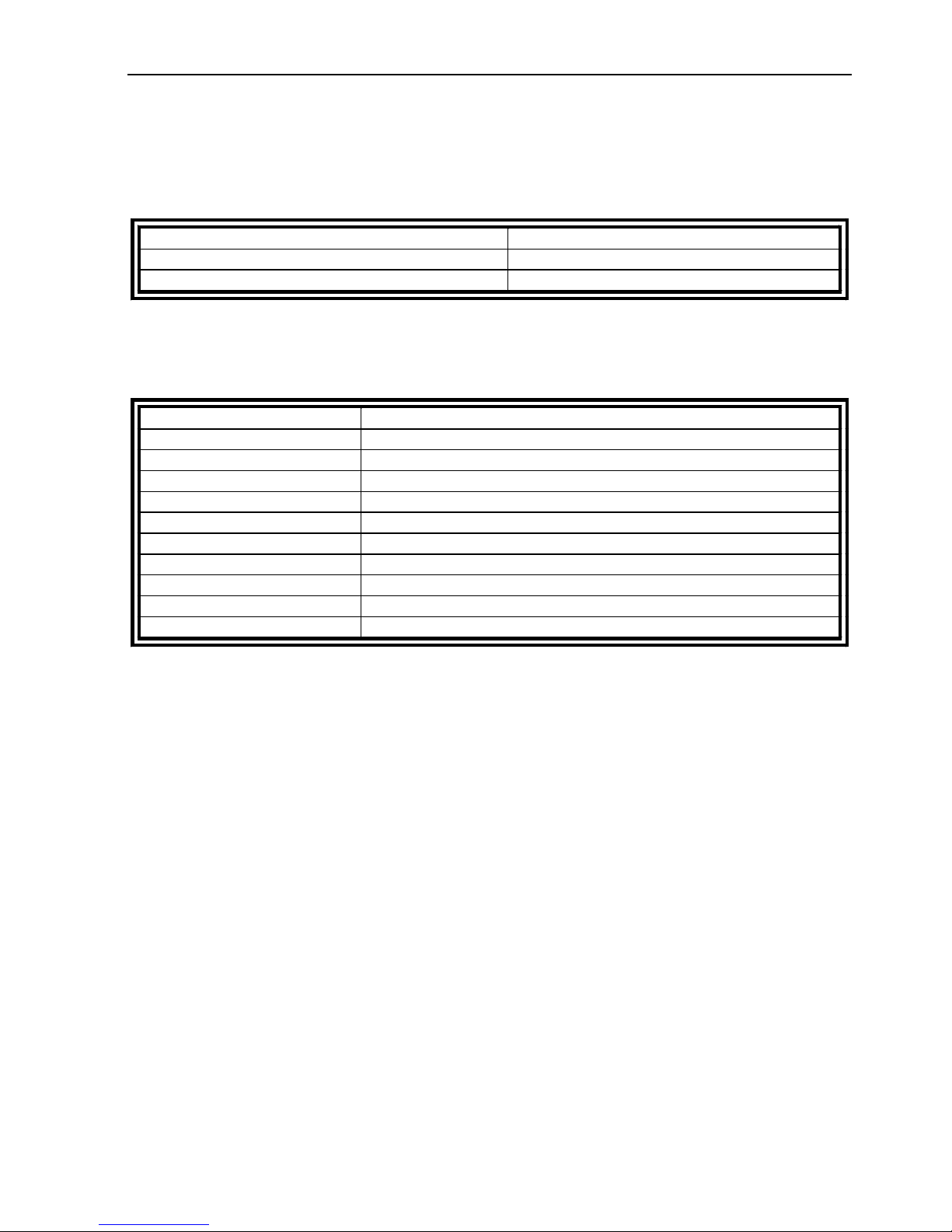
The tool kit contains the following items and is included in the operator’s kit:
Operator Kit
Following is a list of all items found in the kit:
6-5
11034 Rev. A 6. Operator Maintenance
Page 38

6-6
EP 1 Operation Manual Melco Embroidery Systems
Page 39
5. Troubleshooting Guide
PROBLEM
SOLUTIONS
Design
Check the design for short and/or
dense stitches, and edit the
design to remove them
Needles
Replace with a compatible needle
Replace needle
Install the needle correctly (see
needle installation)
burred
Replace needle
Thread
Incorrect thread size for the
needle being used
Replace with a compatible needle
Poor quality thread
Replace with a high quality
thread or spray silicone on thread
cone
S-twist (right twist) thread being
used
Replace with a Z-twist (left twist)
thread
Thread correctly (refer to
threading section)
Upper/bobbin
tension
Loosen upper/bobbin tension
Adjust upper and/or bobbin
tension (see tension section)
tension/stroke
Adjust/replace check spring (refer
to the technical manual)
Fabric and hoops
Fabric is hooped loosely
Tighten fabric in the hoop (see
hooping section)
Inadequate backing allows fabric
to pull into needle plate hole
Increase number of backing
pieces
Rotary hook
Hook timing is incorrect
Adjust hook timing (refer to the
technical manual)
Rotary hook does not rotate
smoothly
Clean, oil, or replace
Gap between the UTC retaining
tab and the rotary hook is too
narrow
Widen the gap (refer to the
technical manual)
Bobbin
Bobbin is damaged
Replace bobbin
Repair or replace bobbin
Thread path
Remove scratches with emery
cloth
Needle depth
Adjust needle depth (refer to the
technical manual)
Thread breakage
POSSIBLE CAUSES
Stitches are too short and/or too
dense
Incorrect needle for thread size
being used
Needle is bent, damaged, or dull
Needle position is incorrect
Needle scarf and/or needle eye is
7-1
Improper threading
Upper/bobbin tension too tight
Ratio of upper thread to bobbin
thread incorrect
Incorrect check spring
Bobbin thread feeds poorly
Scratches or burrs on thread path
Needle depth is incorrect
11034 Rev. A 7. Troubleshooting
Page 40
7-2
PROBLEM
SOLUTIONS
Needles
Replace needle
Replace with a compatible
needle
Install needle correctly (see
needle replacement section)
Needle depth
Needle bar lowest dead point is
incorrect
Adjust needle depth (refer to
the technical manual)
Rotary hook
Adjust gap (refer to the
technical manual)
Hook point is dull
Replace hook
Upper/bobbin
tension
Bobbin thread does not feed
out smoothly
Replace the bobbin and/or
bobbin case
Upper thread does not feed out
smoothly
Adjust the upper tensions
Presser foot
A weak or broken presser foot
prevents the needle from
coming out of the fabric
smoothly
Replace or strengthen the
spring (refer to the technical
manual)
Thread
Thread twist is too tight
Use the appropriate thread or
consult the service department
for suggestions
Thread is too elastic to form an
adequate loop
Check spring
The check spring stroke is too
Adjust the check spring stroke
(refer to the technical manual)
The check spring tension is too
high
Decrease the tension
POSSIBLE CAUSES
SOLUTION
Needle is bent
Replace needle
Needle installation is incorrect
Install correctly (see needle replacement section)
Needle strikes the rotary hook
Adjust hook timing refer to the technical
manual)
Poor needle quality
Replace needle
Dull needle tip
Replace needle
Needle is too small for the fabric
Replace with compatible needle
Needle strikes the needle plate
Adjust position of the needle case (refer to the
technical manual)
Needle strikes the UTC
Reposition the UTC (refer to the technical
manual)
Skipped stitches
POSSIBLE CAUSES
Needle is bent or damaged
Incorrect needle for the thread
size being used
Needle is installed incorrectly
Hook timing is incorrect
Needle breaks
high
EP 1 Operation Manual Melco Embroidery Systems
Page 41
Loose stitches
POSSIBLE CAUSES
SOLUTIONS
Upper thread tension too low
Adjust the upper thread tensions (see tension
section)
Bobbin tension too low
Adjust the bobbin case set screw
Uneven thread size
Replace with quality thread
Upper tension inconsistent
Clean tensioner parts
Rotary hook timing is incorrect
Adjust hook timing (refer to the technical
manual)
Inadequate rotary hook lubrication
Lubricate the rotary hook (see the rotary hook
lubrication section)
Design density too tight
Decrease density (refer to the EDS manual for
design editing)
Gap between UTC retaining tab and hook too
wide
Adjust gap (see the UTC adjustments section)
ISSUE
SOLUTIONS
Bird Nesting
Thread may be wrapped around the hook
assembly; check hook timing and the UTC
retaining finger (refer to the technical manual)
Burrs
Check the needle plate or run the thread test
design
7-3
Other issues
11034 Rev. A 7. Troubleshooting
Page 42

7-4
EP 1 Operation Manual Melco Embroidery Systems
Page 43

Quick
Reference
Guide
for the
EP 1
11034 Revision A
Page 44

EP 1 QUICK REFERENCE
HOOP SELECTION MENU
1. Press [ENTER].
2. Use [UP] or [DOWN] arrows to select
hoop size.
3. Press [ENTER].
MOVE MENU
1. Press [ENTER] 2 times.
2. Use the [LEFT] and [RIGHT] arrows to set
number positions.
3. Use the [UP] or [DOWN] arrows to select
appropriate numbers for move.
4. Press [START] to move hoop to new position.
To display the current hoop position, press
[DOWN] arrow, then [ENTER].
RESET MENU
1. Press [ENTER] to select SYSTEM
RESET.
2. Press [ENTER]; display shows RESET.
3. Press [ENTER] to reset the machine.
4. Press [ENTER] to display MACHINE 01
READY.
5. Press [MENU] to begin the process
again.
7. Press [ALT]+[LEFT] arrow to show design
size in the x-plane.
8. Press [ALT]+[RIGHT] arrow to show
design size in the y-plane.
FRAME MENU
1. Press [ENTER].
2. Select Frame Forward by pressing
[RIGHT] arrow and Frame Back by pressing [LEFT] arrow.
3. Press [DOWN] arrow to return to the
design origin.
4. Press [STOP] to move forward or back
(depending on which is selected) through
the design.
5. Press [START] to return to the design origin.
TRACE MENU
1. Press [ENTER].
2. Use the [LEFT] or [RIGHT] arrow keys
to turn centering ON or OFF.
3. Press [DOWN] arrow to select TRACE
OUTLINE.
4. Press [ENTER] to calculate TRACE
AREA.
5. Press [START] to TRACE DESIGN.
6. Press [ENTER] to ready machine for
sewing.
7. Press [START].
8. Press [START] again to begin embroidering.
Start-up with a Premier Controller
1. Turn on the Premier Controller
2. Insert the SYSTEM DISK into the
Premier’s drive.
3. Turn on the EP 1 peripheral.
4. Remove the SYSTEM DISK and insert the
lettering disk.
5. Set the following PARAMETERS before
entering any lettering:
• FONT
• LAYOUT
• SIZE
• NEEDLE POSITION
• DENSITY
6. Once the PARAMETERS are set, enter lettering from the Premier keyboard.
7. Press [READ DATA].
8. Press [RUN].
9. Press [LETTER A/C] to clear the keyboard
to enter the next file.
Steps in bold type are critical to operation.
DESIGN MENU
1. Press [ENTER] to display the design
name.
2. Select designs using [UP] or [DOWN]
arrows.
3. press [ENTER] to select the design;
display shows RUN DESIGN.
4. Press [ENTER] to set the design
queue.
5. Press [ENTER] to display stitch count and
machine speed.
6. Press [ENTER] to display the design name
and embroidery speed.
 Loading...