

Page 1
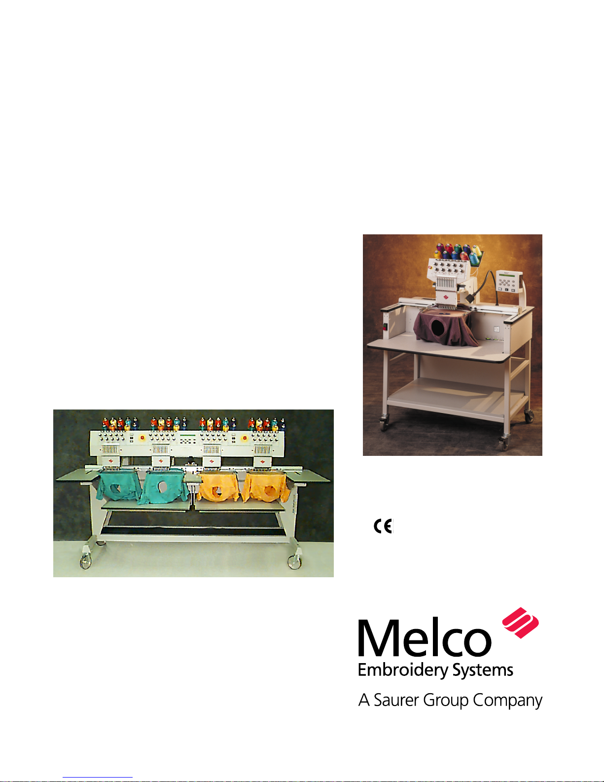
Installation, Operation, and
Maintenance manual for
the EMT 10T, 10/4, and 10/4T
embroidery peripherals
• Single- and four-head tubular
embroidery peripherals
•
Part Number 11817, Revision A
Page 2

1575 West 124th Avenue
Denver, Colorado 80234
United States of America
E-mail: editor@melco.com
© Copyright 1998 by Melco Embroidery Systems
ALL RIGHTS RESERVED No part of this publication may be reproduced, stored in a retrieval system,
or transmitted in any form or by any means (electronic, mechanical, photocopying, recording, or
otherwise) without prior written approval of Melco Embroidery Systems. Melco reserves the right
to revise this publication and to make changes in it at any time without obligation of Melco to
notify any person or organization of such revisions or changes.
All precautions have been taken to avoid errors or misrepresentations of facts, equipment, or
products. However, Melco does not assume any liability to any party for loss or damage caused by
errors or omissions.
All trademarks and trade names contained within this publication are the property of their respective owners.
Printed in the United States of America
Revision A, November 1998
Page 3

Table of Contents
General
EMT 10T Specifications iv
EMT 10/4 and 10/4T Specifications v
Explanation of Symbols vi
1. Installation
Unpacking 1-1
Moving the Peripheral 1-4
Cart Assembly (EMT 10T only) 1-6
Installing the Tabletop (EMT 10/4 and 10/4T only) 1-8
Connecting cables 1-10
First Powerup 1-13
Support Brackets (EMT 10/4 and 10/4T only) 1-15
2. Operation
Hazards of Operation 2-2
Threading 2-4
Tensions 2-5
Keypad 2-6
The Menus 2-8
Main Operator Menu 2-8
Disk Directory Menu 2-8
Design Menu 2-8
Color Menu 2-8
Run Design Menu 2-8
Function Menu 2-9
Options Menu 2-10
Frame Menu 2-12
Reset Menu 2-12
Service/Maintenance Menu 2-12
Head Timing Menu 2-13
4 Hr Lubrication Menu 2-14
8 Hr Lubrication Menu 2-14
40 Hr Lubrication Menu 2-14
80 Hr Lubrication Menu 2-14
480 Hr Lubrication Menu 2-14
2100 Hr Lubrication Menu 2-14
Table of Contents
i
Page 4

Configuration Menu 2-15
Move Function Menu 2-17
Define Custom Hoop 2-18
Test Mode 2-18
Diagnostics Menu 2-19
Disk Drive 2-19
Loading a Design 2-21
Hooping 2-22
Quick Start 2-23
Set Home 2-23
Select Hoop 2-23
Select Orientation 2-23
Center Hoop 2-23
Attach Hoop 2-24
Select a Design 2-26
Color Menu 2-26
Run Menu 2-26
Trace the Design 2-26
Start Embroidering 2-27
Embroidery Speed 2-27
Idle Display 2-27
3. Accessories
Standard Cap Frame 3-1
Wide-Angle Cap Frame 3-6
Sash Frame 3-15
Spider Hoops 3-16
Lamps 3-18
Bobbin Winder 3-19
4. Operator Maintenance
Installing a Needle 4-1
Cleaning 4-2
Lubrication 4-3
Time to oil hook 4-3
8 Hr Maintenance 4-4
40 Hr Lubrication Menu 4-5
80 Hr Maintenance 4-5
480 Hr Maintenance 4-8
2100 Hr Maintenance 4-10
Replacement Parts 4-12
Table of Contents
ii
Page 5

5. Troubleshooting Guide
Thread Breakage 5-1
Skipped Stitches 5-2
Needle Breaks 5-2
Loose Stitches 5-3
6. Error Messages
7. Glossary of Embroidery Terms
Index
Quick Reference Guides
Table of Contents
iii
Page 6

iv
Single-Head Embroidery Peripheral
EMT 10T Specifications
Maximum embroidery speed
1000 stitches per minute
Number of heads
1
Needles per head
10
Dimensions
114cm W x 92cm H x 89cm D
45" W x 36" H x 35" D
Weight
97.7kg
215 lbs
Shipping weight
136.4kg
300 lbs
Power consumption
100 W
Noise level and test conditions
Equivalent continuous A weighted sound pressure level at 1 meter from the floor is 78db.
The peak C weighted instantaneous sound
pressure level is 77db.
The noise level was measured sewing a test
design at 800 spm.
Recommended power conditioning equipment
LC 1800 Line stabilizer (available from Accessory Resource Corporation)
Embroidering field size
28 x 50cm (11 x 19.7") with the Sash Frame
26 x 41cm (10.25 x 16.15") with a tubular frame
Options
Cap frame option
Wide-angle cap frame option
Sash frame option
Bobbin winder option
Cart option
Compatibility
EDS III and Wilcom
Intended use
The EMT 10T is designed to embroider on textile products which are placed easily in a Melco
embroidery hoop. The machine should not be
used on thick leather, wood, plastic, or other
dense material.
The EMT 10T is designed to embroider using
tubular and flat hoops, cap frames, and the
sash frame.
Page 7

v
Multi-Head Embroidery Peripheral
EMT 10/4 and 10/4T Specifications
Maximum embroidery speed
1000 stitches per minute
Number of Heads
4
Number of needles
10 per sewing head
Dimensions
244cm W x 152cm H x 88cm D
96" W x 60" H x 34.5" D
Weight
332kg
730 lbs
Shipping weight
355kg
780 lbs
Power consumption
400 W
Noise level and test conditions
Equivalent continuous A weighted sound pressure level at 1 meter from the floor is 84db.
The peak C weighted instantaneous sound
pressure level is 84db.
The noise level was measured sewing a test
design at 850 spm.
Recommended power conditioning equipment
LC 1800 Line stabilizer (available from Accessory Resource Corporation)
Embroidering field size
28 x 40.6cm (11.02 x 16.0") with the Sash Frame
26 x 41cm (10.25 x 16.15") with a tubular frame
Options
Cap frame option
Wide-angle cap frame option
Sash frame option
Compatibility
EDS III and Wilcom
Intended use
The EMT 10/4 and 10/4T are designed to
embroider on textile products which are placed
easily in a Melco embroidery hoop. The
machine should not be used on thick leather,
wood, plastic, or other dense material.
The EMT 10/4 and 10/4T are designed to
embroider using tubular and flat hoops, cap
frames, and the sash frame.
Page 8
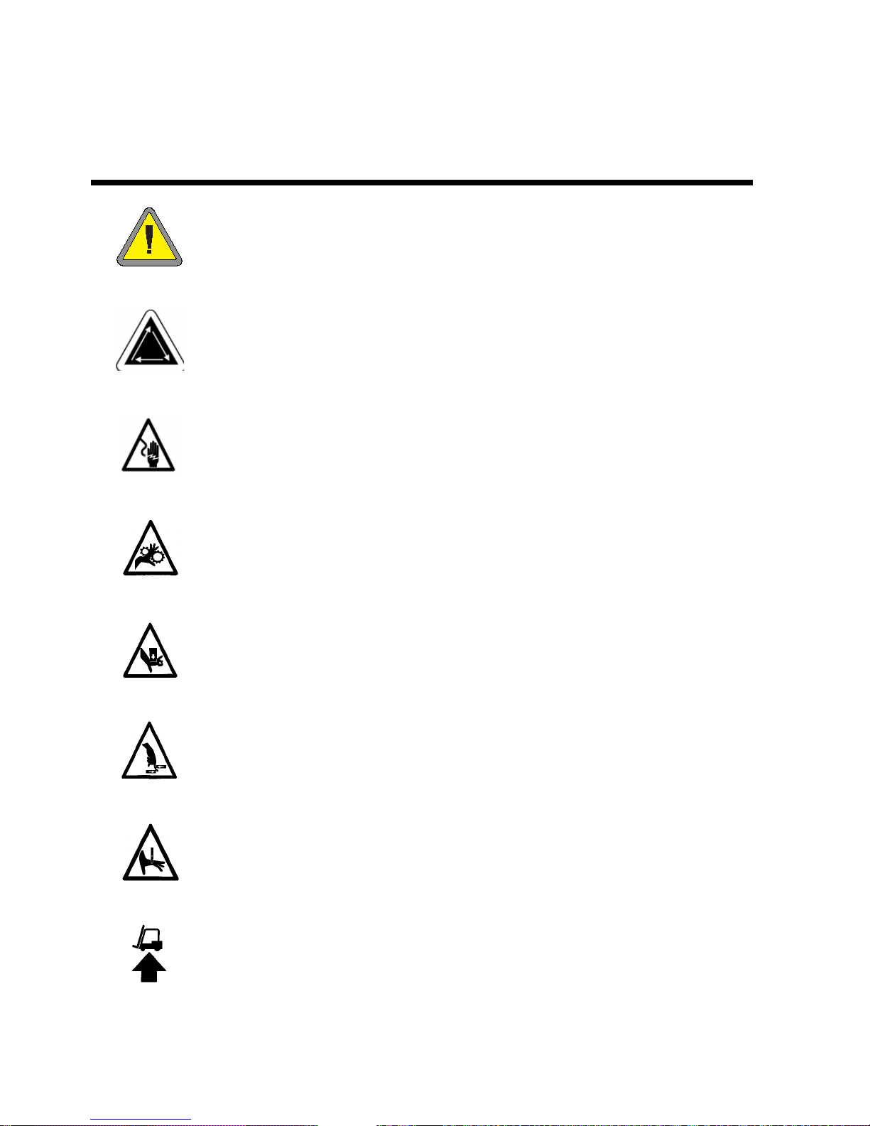
Explanation of Symbols
Caution!
Indicates a machine component will move. Keep clear!
Shock hazard. No user replaceable parts behind this label. Do not open!
Pinch point, Keep clear!
Pinch point, Keep clear!
Pinch points, Keep clear!
Needle pinch point, Keep clear!
Use a forklift.
vi
Page 9
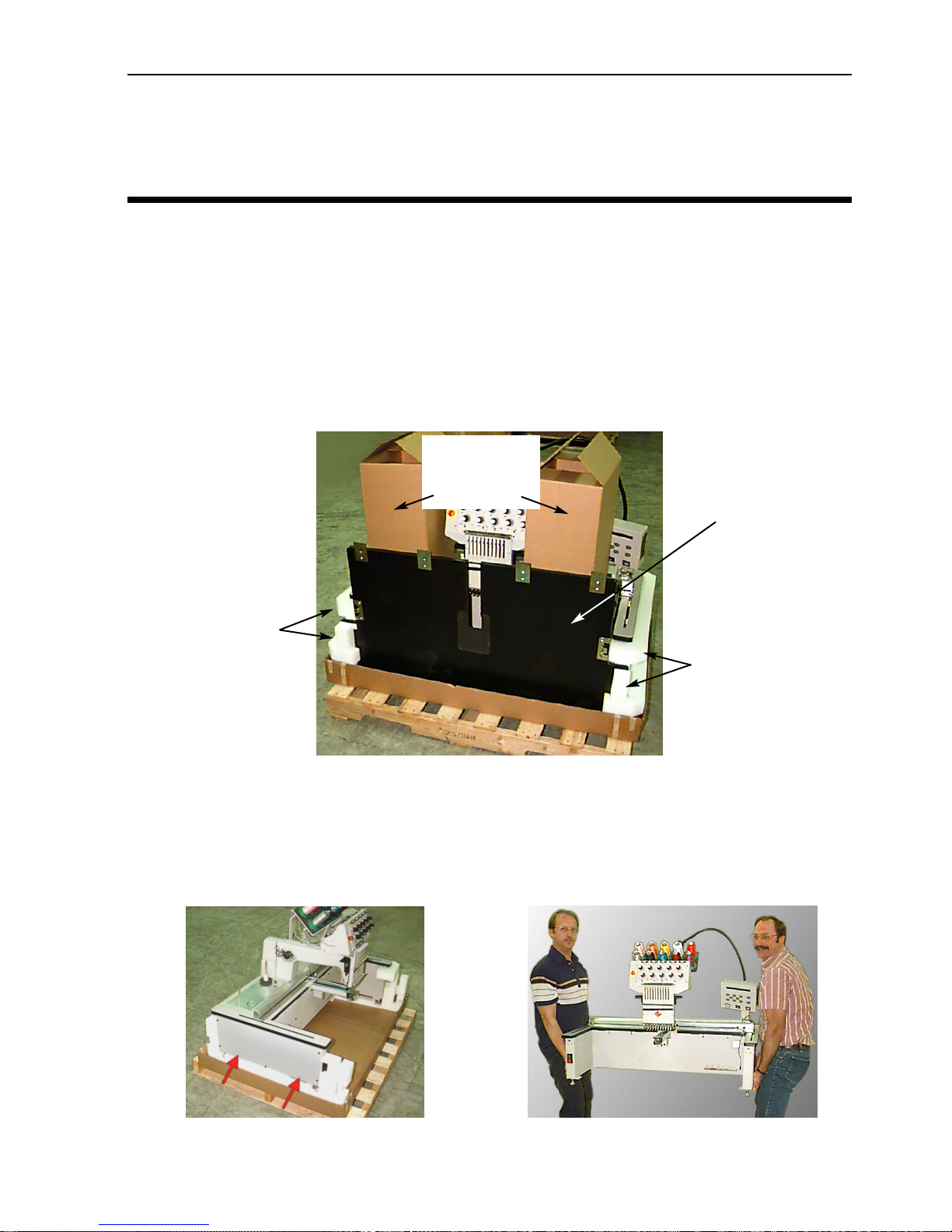
Unpacking 1-1
11817 Rev. A 1. Installation
1.Installation
Read the entire manual before operating the machine. Save all packing material; if you ever need
to move the peripheral, use the original packing material.
Unpacking
EMT 10T
Remove the packing straps holding the box together using a knife. Lift off the top of the box, and
then remove the sides of the carton. Remove the plastic bag enclosing the equipment. When the
plastic is off, refer to Figure 1-1 for further instructions.
Prepare the designated area for the peripheral. If you have purchased the cart option, you must
clear a temporary location for the machine (until you have assembled the cart). If you purchased
the foot option, install the 4 feet before removing the machine from the box. Two people are
required to lift the EMT 10T. Refer to Figure 1-2 to locate the hand-holds, and lift as shown in Figure 1-3.
Figure 1-1
Remove these
boxes (one contains the opera-
tor kit)
Remove the
tabletop
Remove these
foam braces
Remove these
foam braces
Figure 1-2 Figure 1-3
Page 10
1-2 Unpacking
Operation Manual for the EMT 10T, 10/4, and 10/4T Melco Embroidery Systems
EMT 10/4 and 10/4T
There are two versions of the EMT 10/4 and 10/4T machines, and each are shipped in a different
way. Domestic models are shipped with a “coffin-style” crate surrounding the heads. International
models are shipped in a full crate and are packed on a palette within the crate. Determine which
style you have, and refer to the pertinent section.
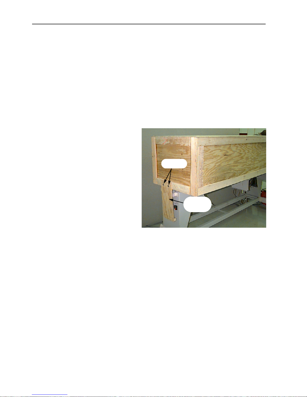
Domestic models
Two people are required to unpack the EMT 10/4 or 10/4T. Be careful when unpacking your new
peripheral. On one end of the “coffin-style” crate is a wooden cover that protects the power
switches during shipment (refer to Figure 1-
4). 2 bolts secure this cover to the crate.
remove both bolts, and remove the cover.
Along the back of the crate are 2 “L” shaped
brackets; these brackets hold the crate to the
frame, protecting the heads. Remove the
bolts holding the bracket to the crate, then
remove the bolts holding the bracket to the
frame. When the bolts have been removed,
remove the bracket.
The crate weighs 115lbs (52.3kg) and is very
awkward, so use caution. With one person
standing at each end of the crate, carefully
lift the crate until it is clear of the heads.
Remove the crate. Store all packing materials
and hardware in a safe place. Reuse the
packing materials if you ever relocate the
peripheral.
Figure 1-4
Bolts
Wood-
en cover
Page 11
Unpacking 1-3
11817 Rev. A 1. Installation
International models
Two people and a forklift are required to unpack the EMT 10/4 or 10/4T. Be careful when unpacking your new peripheral. On one end of the crate is a “window” of wood. This end is the door.
Open the door by removing the nails from around the perimeter. Next, remove the nails from
around the bottom perimeter of the box. Slide the crate off the pallet. Use a forklift to lift the
peripheral off the pallet. Place the forks in the locations shown below.
Figure 1-5
Do not make contact with
the motors located here!
Page 12
1-4 Moving
Operation Manual for the EMT 10T, 10/4, and 10/4T Melco Embroidery Systems
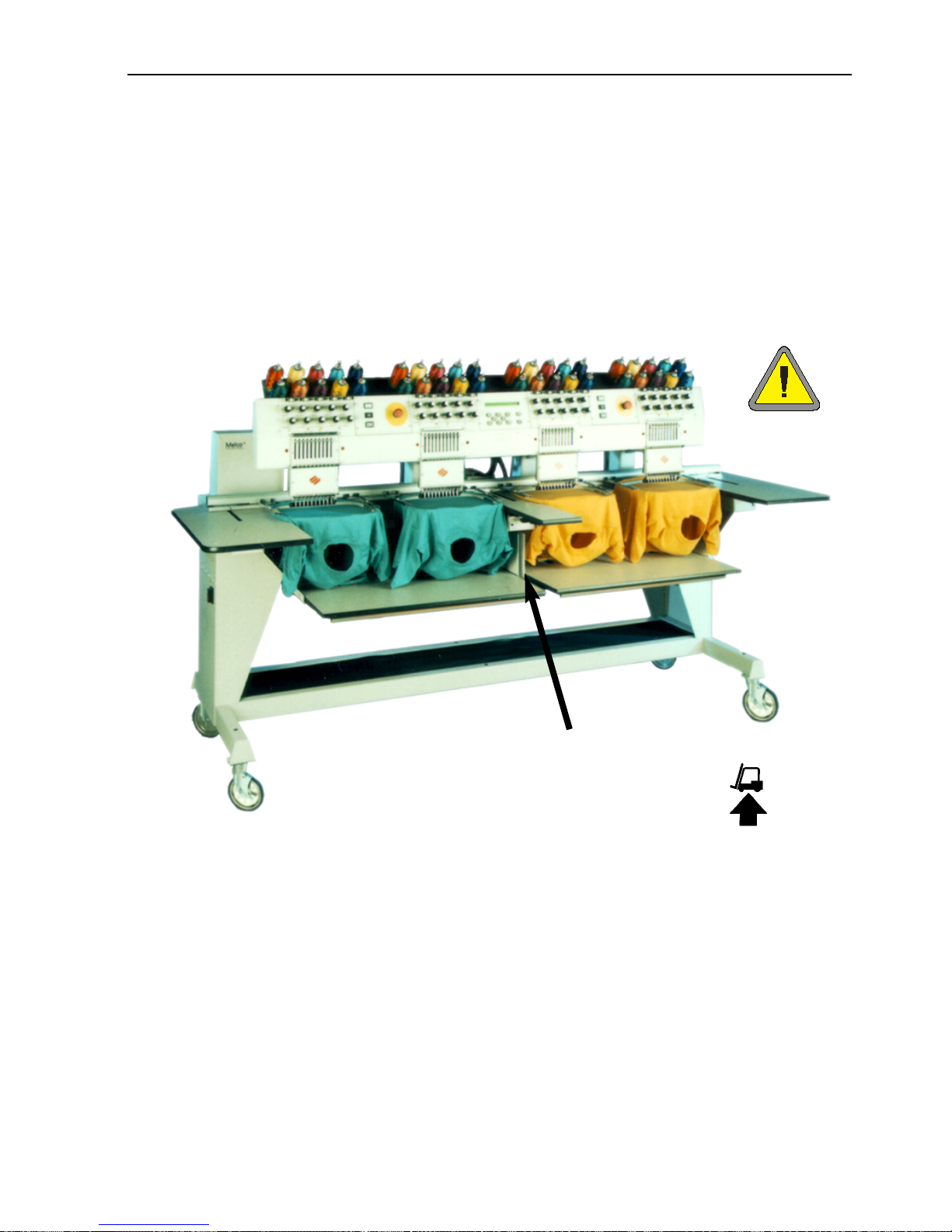
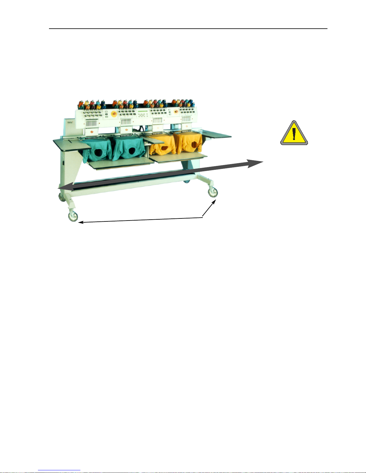
Moving the Peripheral
Make sure you leave enough room around your peripheral
to have easy access to all sides.
EMT 10T
Use two people to lift the machine; use the hand-holds
shown in Figure 1-6.
If the machine is on a cart, disengage the brakes on the
indicated wheels before attempting to move the machine.
Engage the brakes when the machine is in the desired
location. Observe the precautions below. You cannot remove the machine from the cart without
first removing the 4 bolts securing the machine to the cart.
Figure 1-7
Push carefully in the
directions shown or
the cart may tip.
Figure 1-6
Brakes
Page 13
Moving 1-5
11817 Rev. A 1. Installation
EMT 10/4 and 10/4T
Move the machine as indicated below. Disengage the brakes on the indicated wheels before
attempting to move the machine. Engage the brakes when the machine is in the desired location.
Figure 1-8
Push only in the direction of
the arrows when moving
the machine more than a
short distance.
Brakes
Page 14
1-6 Assembly
Operation Manual for the EMT 10T, 10/4, and 10/4T Melco Embroidery Systems
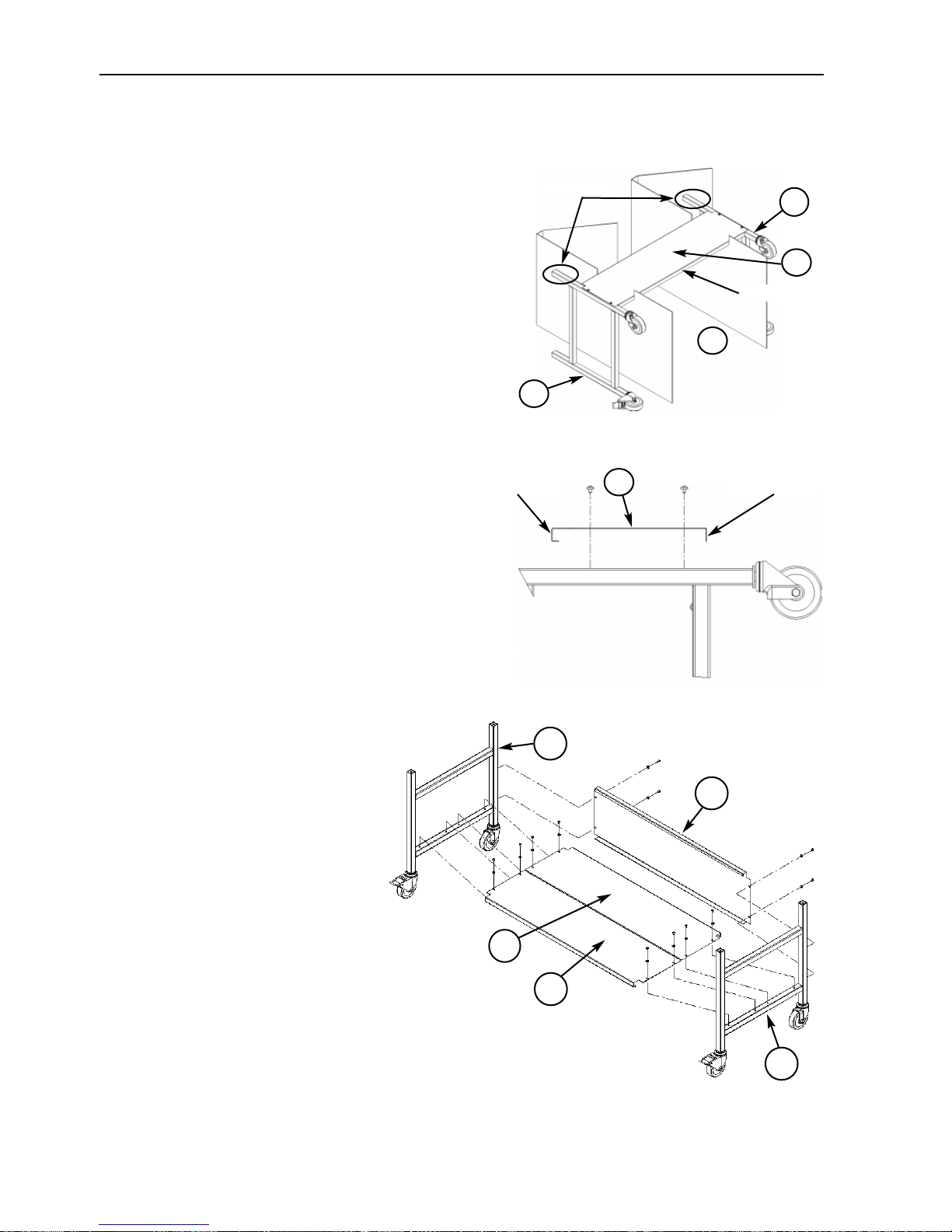
Cart Assembly (EMT 10T Only)
If you purchased the optional cart with the EMT
10T, you must assemble the cart and mount the
peripheral on the cart. The following section
describes how to assemble the cart and attach the
EMT 10T. To dismantle, reverse these steps.
The cart has 5 pieces. They attach as shown in Figure 1-11. Use the enclosed hardware to build the
cart. Pieces 1, 4, and 5 are identical to each other.
Pieces 2 and 3 are also identical to each other.
Referring to Figure 1-9 and 1-10, lay piece 1 on top
of the existing cardboard packaging with the
straight flange pointing down. Attach piece 2 with
wheels on the same end as the straight flange on
piece 1 (see Figure 1-10). The wheels with the
brakes on them should be on the ground as shown
in Figure 1-9. Insert the necessary screws (M5
phillips head screw with a flat washer between the
screw and the cart piece) securing them tightly.
Attach piece 3 the same way. While standing in
area indicated in Figure 1-9, grasp and carefully lift
cart off of cardboard and place all four wheels onto
floor.
Referring to Figure 1-11, place pieces
4 and 5 resting on top of the cross
bars of pieces 2 and 3 and piece 4
resting on the straight flange of piece
1. The straight flange of pieces 4 and
5 will be placed together in the mid-
dle of the cart assembly. Insert the
necessary screws (M5 phillips head
screw with a flat washer between the
screw and the cart piece) securing
them tightly.
Figure 1-11
1
2
4
3
5
Figure 1-9
1
2
3
x
Stand here
Grasp here
Figure 1-10
Straight flange
1
Bent flange
Straight Flange
Page 15
Assembly 1-7
11817 Rev. A 1. Installation
Mounting the EMT 10T on the cart
1. Remove the main tabletop.
2. Remove the side covers; there are 5 screws holding each
side cover in place (see Figure 1-12). Use the #2 Phillips
head driver included in the operator kit to remove the
screws.
Caution! The side panels are heavy; if
dropped, damage may occur.
3. Lift the EMT 10T (2 people are required) and carefully place the machine on the “pillars” of
the cart. The 4 holes where the feet attach should be aligned with the 4 holes on the cart’s
pillars. If the holes do not match up then slightly loosen all of the cart screws for flexibility.
4. Secure the machine to the cart using the M6 socket-head cap screws, a flat washer, and a
lock washer (provided with the cart). Refer to Figure 1-13.
Install the flat washer, then the lock washer, then the bolt.
5. Make sure the cart is standing straight, tighten all screws.
6. Replace the side covers.
7. Replace the tabletop (if desired).
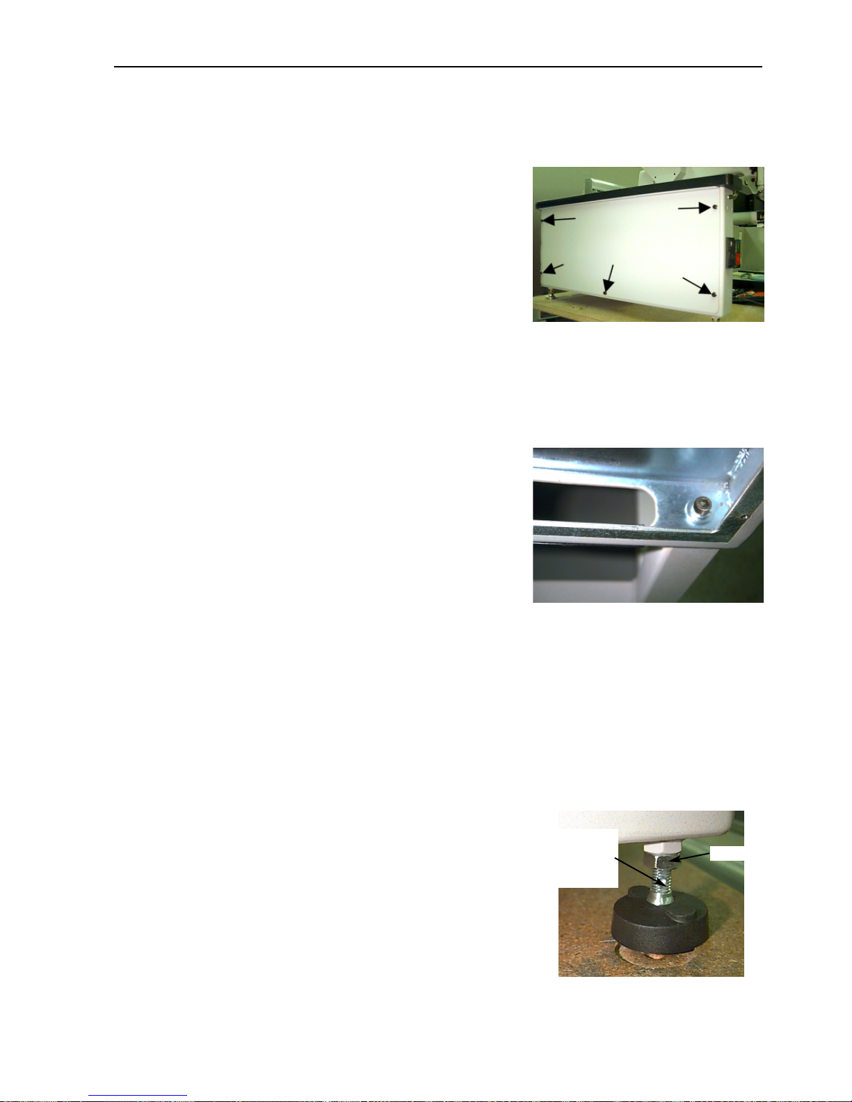
Installing the feet
If you have purchased the Foot option with your EMT 10T, refer to these steps to install the feet.
1. Remove the main tabletop.
2. Remove the side covers; there are 5 screws holding each side cover in place (see Figure 1-12).
Use the #2 Phillips head driver included in the operator kit to remove the screws.
Caution! The side panels are heavy; if dropped, damage may occur.
3. Working on one side at a time, raise the machine and support it securely. The machine should
be lifted approximately 4" (10cm).
4. Install the 4 “feet” on the peripheral (see Figure 1-14). Turn
the indicated flat section of the stem with an adjustable
wrench to install or remove the foot on to the peripheral.
5. Place the machine on the surface where you intend to use it,
and level the machine. Adjust the appropriate feet by turning
the stem up or down and sequre with the lock nut against
the peripheral.
Figure 1-12
Screws
Figure 1-14
Turn at
the flats
to adjust
Figure 1-13
lock nut
Page 16
1-8 Tabletop
Operation Manual for the EMT 10T, 10/4, and 10/4T Melco Embroidery Systems
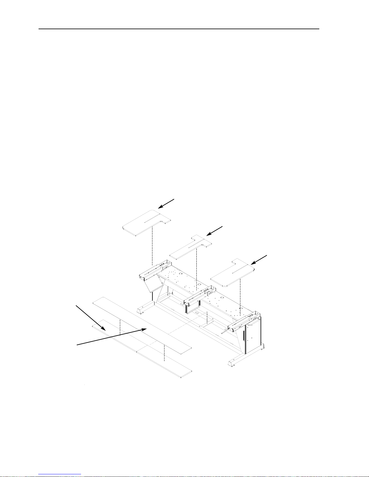
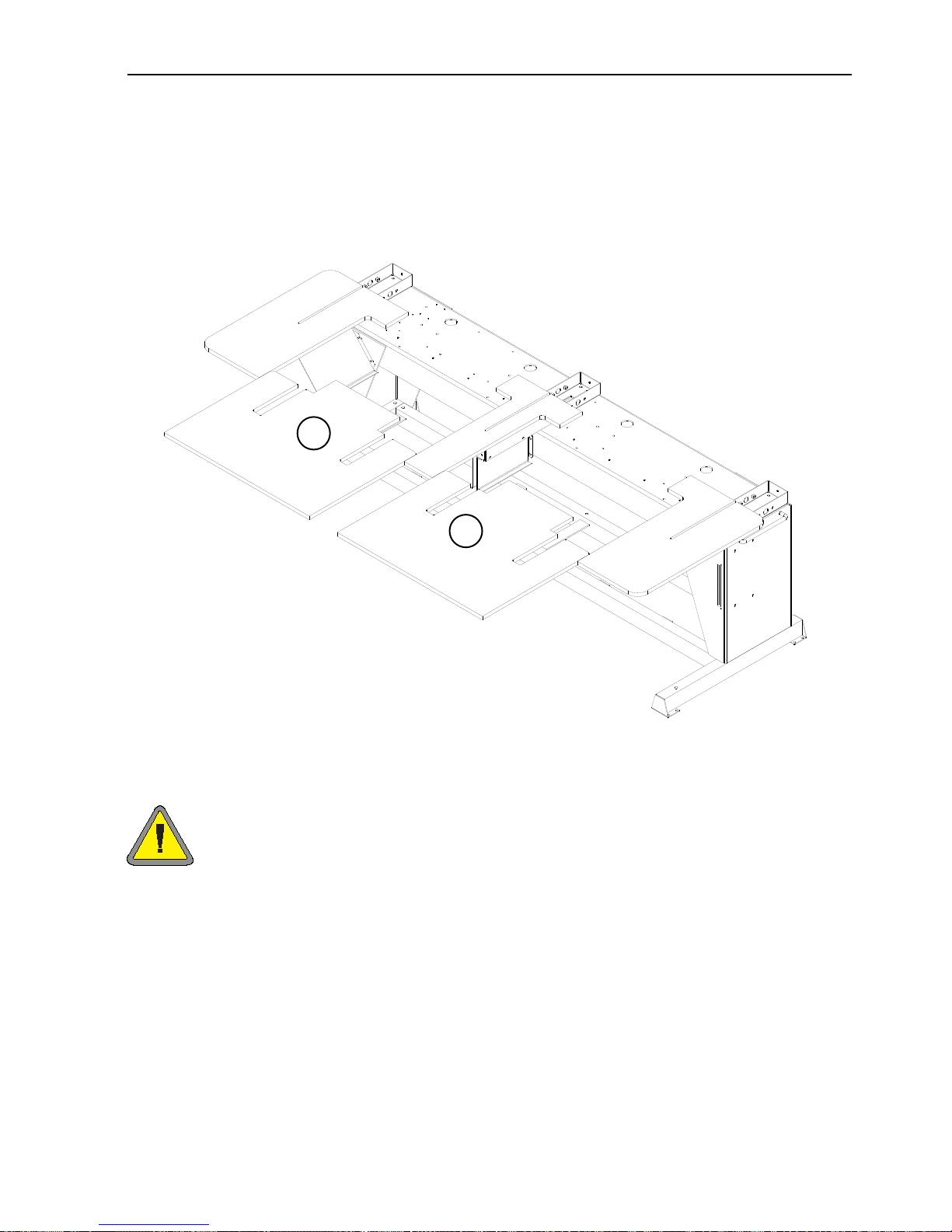
Installing the tabletop (EMT 10/4 Only)
You only need to install the tabletop on the EMT 10/4 if you are going to embroider flat goods or
use the sash frame. To install the tabletop, refer to the instructions below.
The tabletop is shipped in five parts (see Figure 1-15). The two ends and the center section slide
into place in the positions shown in Figure 1-15. The remaining two sections slide into place as
shown in Figure 1-16. This design makes it easy to remove the tabletop to embroider tubular
goods, to embroider with a cap frame, or to perform routine maintenance.
1. Using four thumb screws for each section, slide the right, left, and center sections into the
metal channels on the table. The screws are inserted from the underside of each piece.
2. There is a 2-section shelf and a covering mat that comes with the table top assembly (see Figure 1-15). Place the shelf pieces on top of the brackets located in the base of the machine and
lay the mat on top of the shelf pieces.
Figure 1-15
2-piece shelf
Rubber
mat
Left section
Center section
Right section
Page 17
3. Slide the last two pieces into place (see Figure 1-16). They fit on the table support tabs on the
end and center sections.
4. Tighten the thumb screws under the table to secure the pieces.
Special note on the tabletops
You MUST remove all 5 tabletop inserts before embroidering tubular goods or caps
on the EMT 10/4 or 10/4T. Failure to do so may result in damage to the equipment or
bodily injury. You may use parts A and B of the tabletop (in Figure 1-16) in the LOWERED POSITION to support heavy garments during tubular embroidery only.
Tabletop 1-9
11817 Rev. A 1. Installation
Figure 1-16
A
B
Page 18
1-10 Connecting cables
Operation Manual for the EMT 10T, 10/4, and 10/4T Melco Embroidery Systems
Connecting cables
Power requirements
Melco suggests using a dedicated line with a line conditioner (available from Accessory Resource
Corporation). Do not use any power cable that appears to be damaged. If your power cable
appears to be damaged, order a new power cable from your Melco representative.
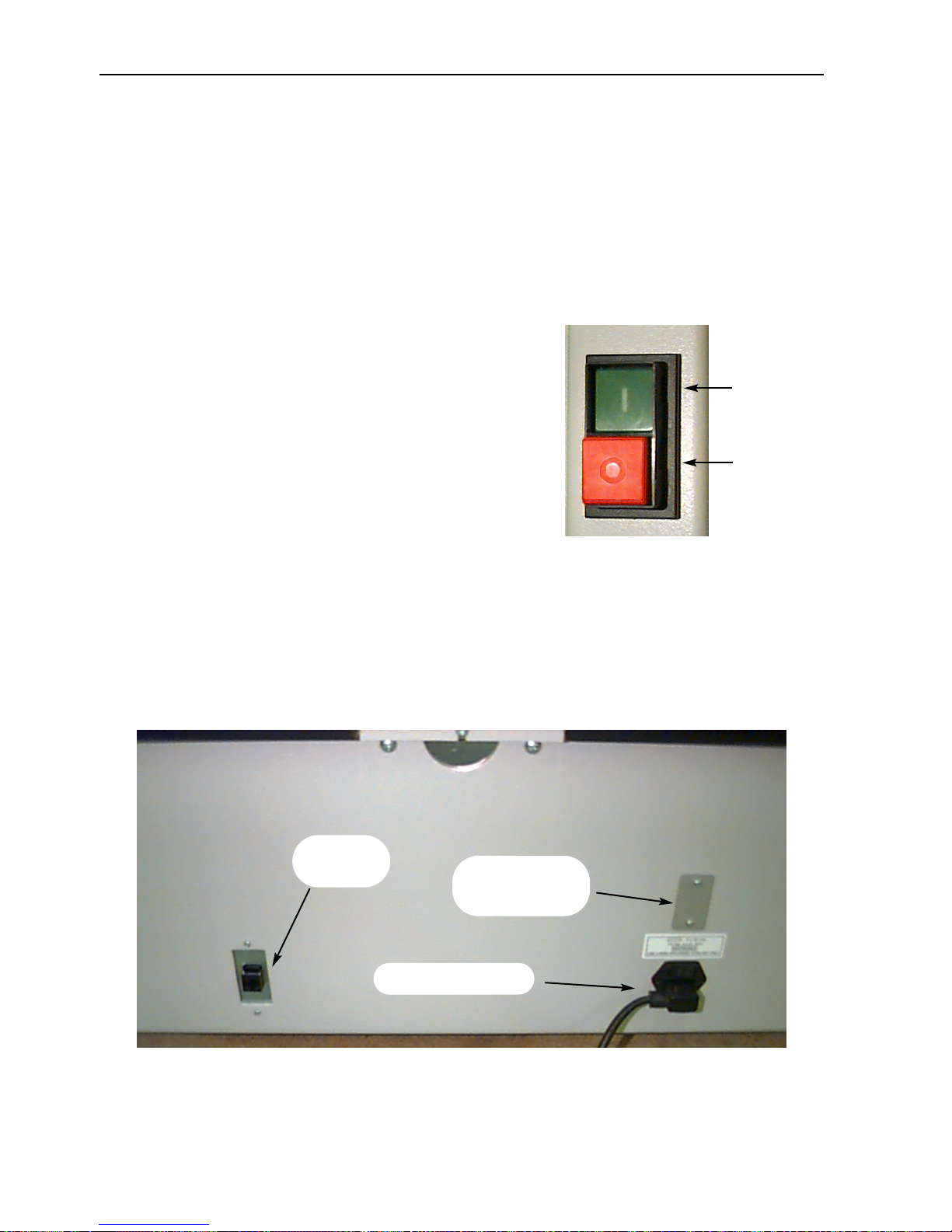
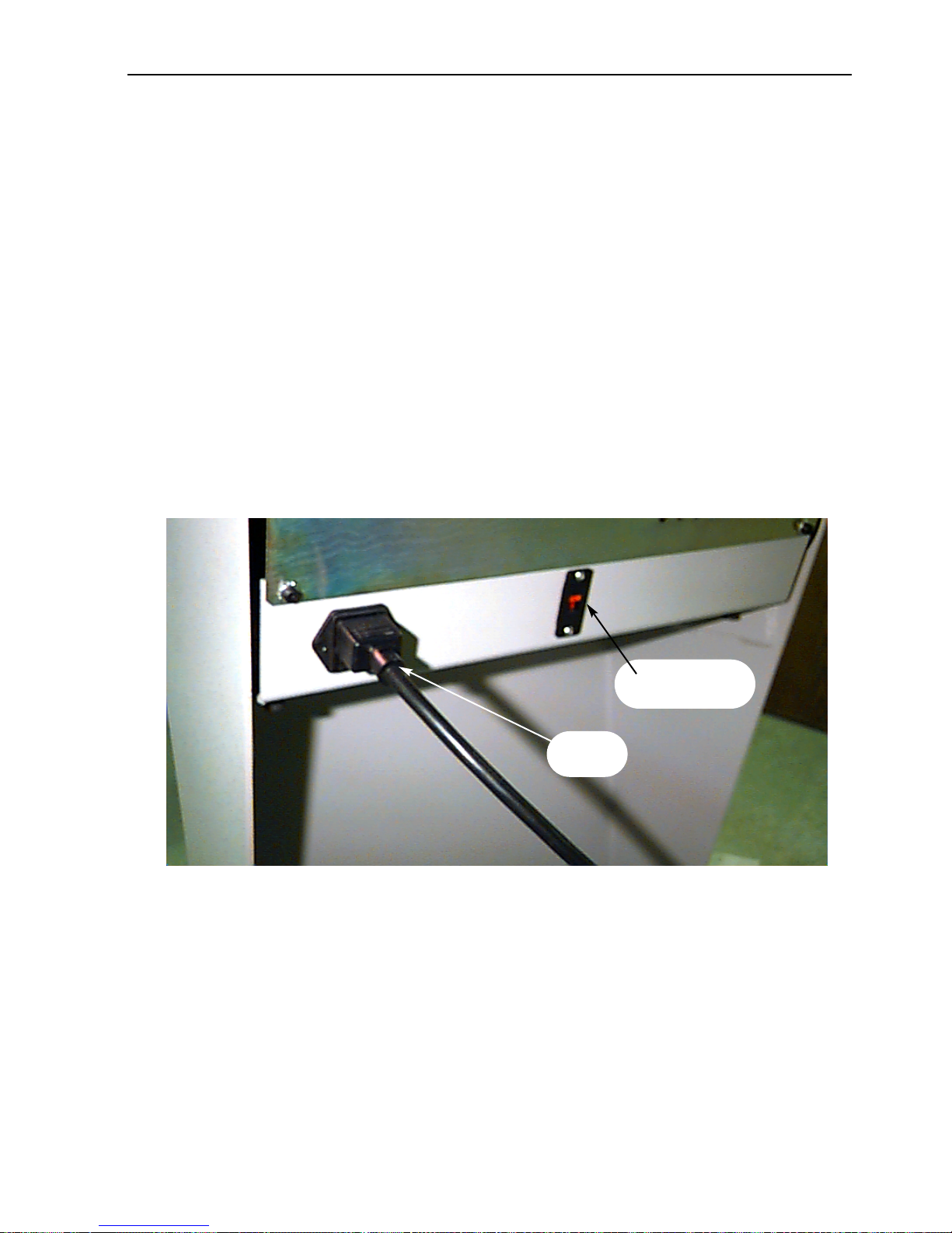
EMT 10T
1. Figure 1-17 shows the power in the ON position. Turn
the power OFF before connecting ANY cables.
2. If your peripheral is equipped with a voltage selector
switch, set it to the correct position for your area.
3. Plug the power cable to the rear of the unit as shown in
Figure 1-18.
4. Plug the other end of the cable into the line conditioner.
5. Connect the line conditioner to the power source.
Note: The fuses have been installed for the voltage in your area; if you use a voltage other than
the factory preset, make sure you replace the factory fuses with appropriately rated fuses.
Refer to Chapter 4 for more information about fuses.
Figure 1-18
Net-
work cable
Voltage
selector switch (if
applicable)
Rear of peripheral
Power cable plug
Figure 1-17
ON
(green)
OFF
(red)
Page 19
Connecting cables 1-11
EMT 10/4
1. Figure 1-17 shows the power in the ON position. Turn the power OFF before connecting ANY
cables.
2. If your peripheral is equipped with a voltage selector switch, set it to the correct position
(115VAC or 220VAC) for your area.
3. Plug the power cable to the leg of the unit as shown in Figure 1-19.
4. Plug the other end of the cable into the line conditioner.
5. Connect the line conditioner to the power source.
Note: The fuses have been installed for the voltage in your area; if you use a voltage other than
the factory preset, make sure you replace the factory fuses with appropriately rated fuses.
Refer to Chapter 4 for more information about fuses.
11817 Rev. A 1. Installation
Figure 1-19
Voltage
selector switch
Power
cable
Page 20
1-12 Connecting cables
Operation Manual for the EMT 10T, 10/4, and 10/4T Melco Embroidery Systems
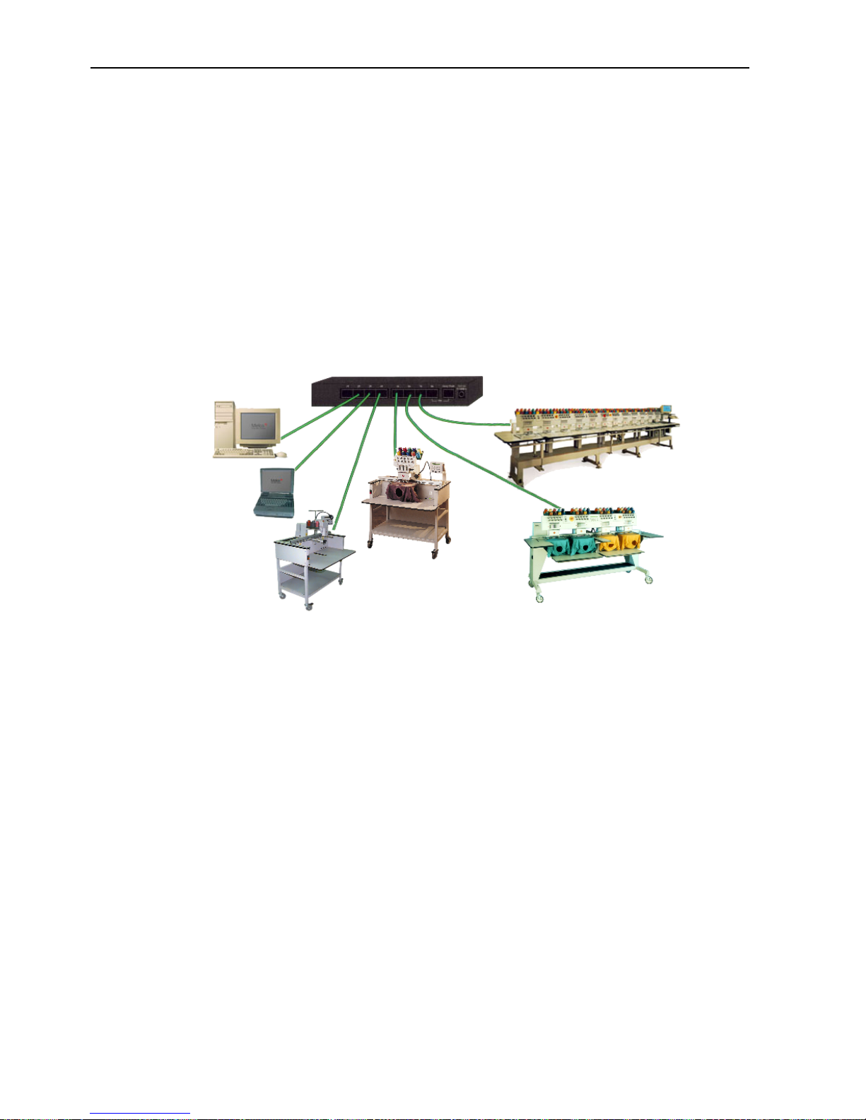
Attaching the peripheral to a network
The EMT product line is compatible with Ethernet network technology. With Ether net, peripherals
connect to a wiring hub, and the hub connects to an EDS III or Wilcom computer. The hub is a
small electronic device that contains a number of cable jacks and diagnostic lights. The peripherals, EDS III computers, and Wilcom computers can plug into any port on the hub. You can connect
as many peripherals or computers as your hub can hold. If you have more peripherals or computers than your hub has ports, you can daisy-chain 2 (or more) hubs together.
Refer to Figure 1-20 for a sample Ethernet network.
*Note: You may have as many licensed EDS III systems operating on an Ethernet network as you
choose. Each computer running EDS III on the network must have a licensed EDS System
(including the dongle) installed to operate properly.
Figure 1-20
Ethernet hub
EMT 10/12
EDS III
Computer
*
EDS III
Laptop
Each cable may be up to 100 meters (327 feet) long. Hubs may be daisy-chained
for more capacity or distance.
*
EMT Products
Page 21
First powerup 1-13
First powerup
Diagnostic tests
Every time the peripheral powers up, it goes through a series of diagnostic tests. A series of messages will flash on the display. These diagnostic tests verify the proper function of the peripheral’s
CPU and the network card (if present). After the tests, the BIOS revision level will be displayed; if
you are running an Ethernet network and no EDS or Wilcom computer is on-line, the display may
read: Insert Boot Disk.
If any of the diagnostics fail, the CPU will halt and the machine will not boot. This indicates a
problem with the CPU. Contact your Melco Service Representative.
Configuring the peripheral
The first time the machine is turned on, it must be configured with a peripheral program and unit
name. This information is stored in memory and retrieved during each power up. If the peripher-
al is not configured correctly, it will not operate properly and may be damaged.
The unit name is a unique address for each machine. The machine uses the unique EtherNet
address as a default. You may change this to any 16 (or less) character name. Use a unique name
for each machine if you have more than one machine on your network.
To configure the peripheral:
1. Turn ON the power.
2. Ignore any message flashing on the LCD.
3. Press and hold at the same time within 12 seconds after you turn
on the power.
4. Continue to hold the keys until the machine beeps, then release.
5. The LCD should display the model name; press or to scroll to the correct
model name for your machine.
6. Press and the peripheral program is set.
7. Press or to change the characters in the name and press or
to move to the next or previous character.
8. Press to set the unit name.
The machine should now be properly configured.
11817 Rev. A 1. Installation
▼▲▼▲▼
▲
▲
▲
▼
▲
Page 22

1-14 First powerup
Operation Manual for the EMT 10T, 10/4, and 10/4T Melco Embroidery Systems
Language selection
All Melco products use English as the default language. If you wish to change the display to a different language, follow these steps to select the machine language:
Note: The machine must be configured before you can change the display language.
1. Press to enter Language Selection
2. Press or to scroll through the available language selections.
3. When the desired language is selected, press to return to the Main Menu.
Note: You can only change the language after the machine has downloaded the RSA files.
▲
▼
▼
▲
▲
▲
▼
▲
▼
▼
▲
▲
Page 23
Support brackets 1-15
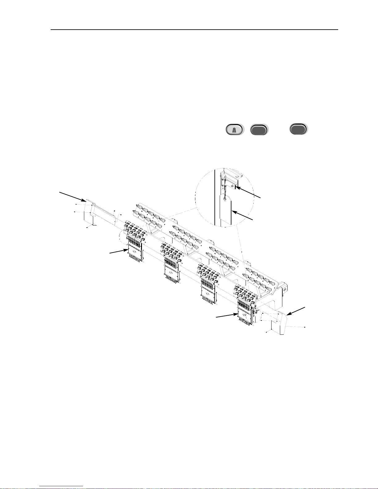
Support brackets (EMT 10/4 or 10/4T only)
Two supports brackets, one on the right needle case (sewing head 1) and one on the left needle
case (sewing head 4) hold the needle case during shipping; these brackets must be removed prior
to operation. Follow the steps below:
1. Remove the two supports (a caution tag is attached to each). Refer to Figure 1-21.
2. Manually move the needle case to needle 5 or 6 using or .
3. Install the left and right end covers, as shown in Figure 1-21. The screws for the covers are
installed on the machine.
11817 Rev. A 1. Installation
▼
▲
▼
▲
Figure 1-21
Left end
cover
Caution tag
Support bracket
Sewing
head #4
Sewing
head #1
Right end
cover
Page 24

1-16 Support brackets
Operation Manual for the EMT 10T, 10/4, and 10/4T Melco Embroidery Systems
Page 25
Operation 2-1
11817 Rev. A 2. Operation
2.Operation
This chapter outlines machine operation; in addition, operators must attend a Melco approved
training course prior to operating the machine.
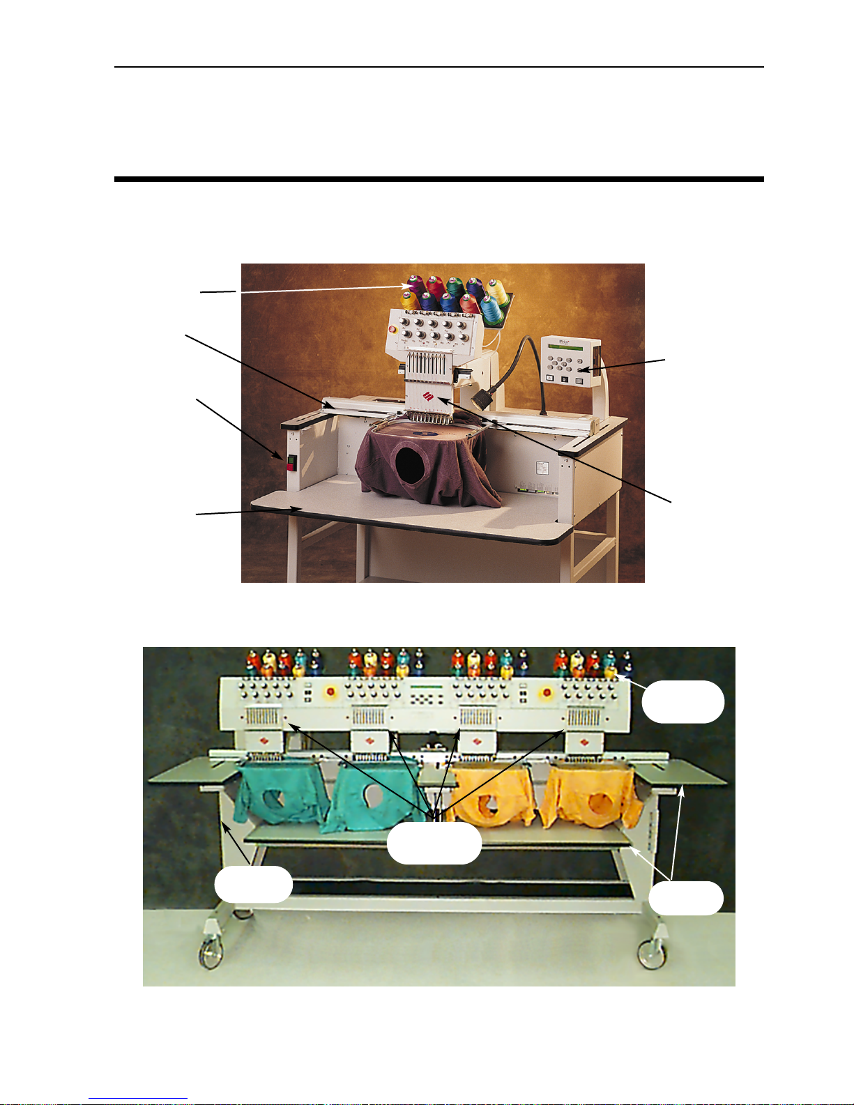
Figure 2-2
Thread
tree
Power
switch
Needle
cases
Table-
Figure 2-1
Power switch
Table
Thread tree
Needle case
Keypad
X-carriage
Page 26
2-2 Operation
Operation Manual for the EMT 10T, 10/4, and 10/4T Melco Embroidery Systems
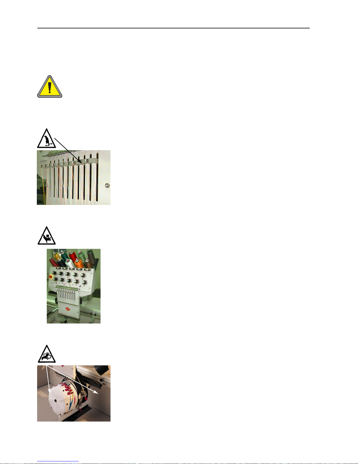
Hazards of operation
Caution! Below are risk areas or danger points encountered during operation. Always wear eye protection while operating the
machine to prevent injury in the event of a needle break. Do not
wear loose or baggy clothing when operating the machine.
Take-up Lever Oscillation
Do not touch the take-up levers during operation
Needle Case Movements
Do not place hands or other objects on or around the needle case during operation.
Cap Frame Pinch Points
Do not touch the cap frame, driver, or driver bar during operation.
Page 27
Operation 2-3
11817 Rev. A 2. Operation
Exposed Needles During Operation
Do not place body parts or other foreign objects under the needles
during operation.
Pinch Points
Do not rest hands or other objects on the table top during operation.
Do not reach behind the x-carriage during operation with or without
table top in place.
Rotary Hook Rotation
Do not attempt to change bobbin thread during operation. Do not
place hands or other objects in the rotary hook area during operation.
Do not operate the machine without the hook guards in place.
Page 28
2-4 Operation
Operation Manual for the EMT 10T, 10/4, and 10/4T Melco Embroidery Systems
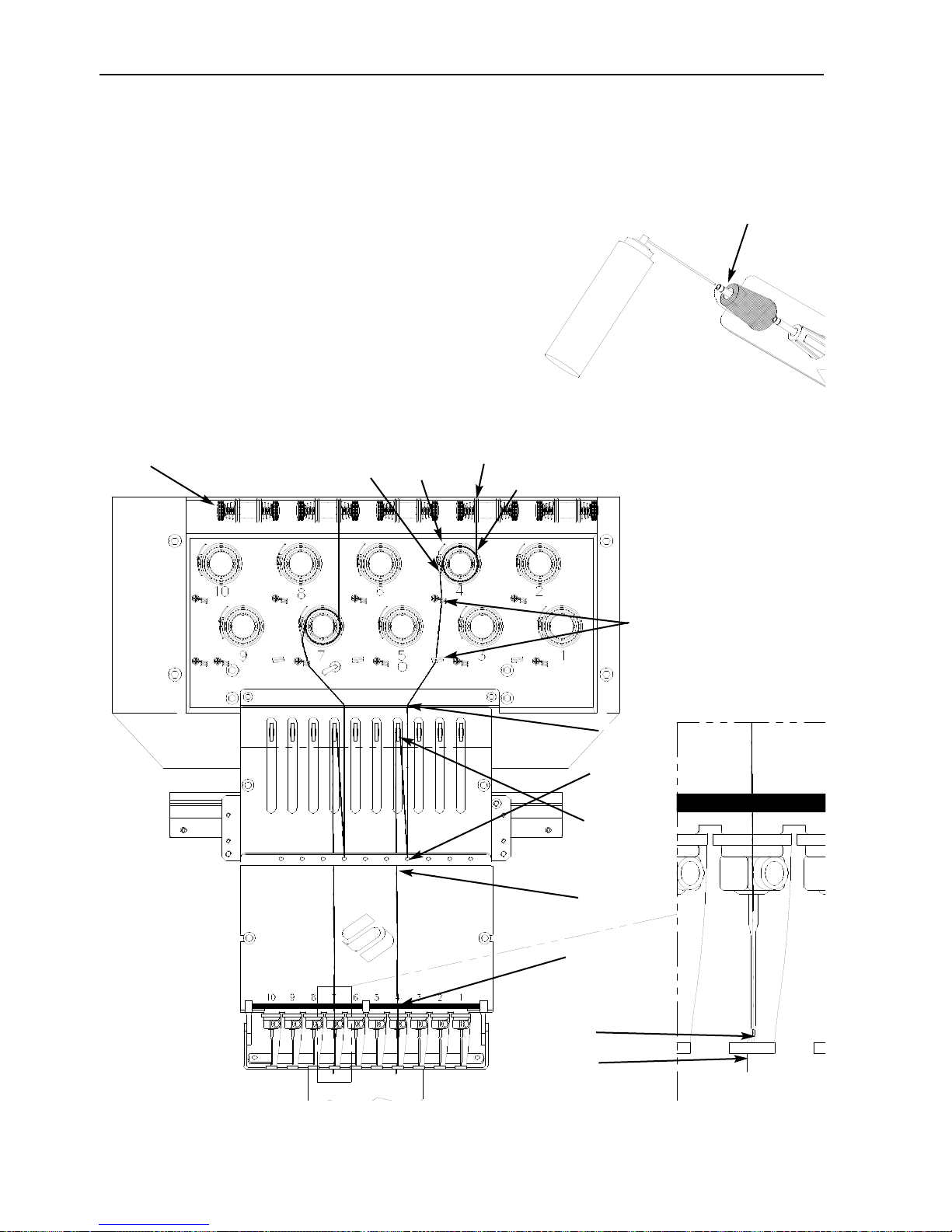
Threading
Push the metal thread tubes up from behind the head, and
remove the magnetic strips from the front of the heads.
Place a cone of thread onto the stand and push the first
few inches of thread into the supply tube. Use a can of
compressed air to blow the thread through the supply tube.
If you do not have compressed air, use the clear monofilament (approximately 24" or 70cm long) provided in the
operator’s kit. There is a small hole behind the pretensioners; Push the monofilament into this hole and up
through the supply tube, then “hook” the thread on the
cut and pull the thread through the tube.
Figure 2-3
Figure 2-4
THE THREAD PATH
Numbers here represent
numbered steps from
the following page.
1
2
3
4
5
6
7
8
9
10
11
12
Pretensioner
The thread tube should extend
approximately 0.5" above the
thread cone
Page 29

Operation 2-5
11817 Rev. A 2. Operation
1. Pull the thread from the guide hole down between the pretensioner disks.
2. Route the thread down through the pretensioner, between the two metal wheels.
3. Pull the thread down to the main tensioner and wrap the thread around the disk clockwise 1
1
/2
times.
4. Route the thread through the tension take-up spring. When you tug on the thread, the take-
up spring should move and break contact with the thread break sensor post.
5. Route the thread down through the thread guide post(s). Threads using the top tensioners
have two posts, threads using the bottom tensioners have one post.
6. The upper thread guide is just above the the take-up levers. Route the thread through it.
7. The middle thread guide is just below the take-up levers. Route the thread though the hole
facing outward, from back to front.
8. Bring the thread through the take-up lever eye, from right to left.
9. Route the thread straight down to the middle thread guide, through the hole facing down-
ward.
10. Drop the thread through the lower guide, just above the presser foot.
11. Run the thread through the eye of the needle, from front to back.
12. Pass the thread through the center of the presser foot.
13. Pull on the thread until you feel tensioner pressure.
14. Set the tension to equal 80-120 grams required to pull the thread at the needle end.
15. Fasten the thread to the retainer spring and trim the end to about an inch in length.
Tensions
Embroidery tensions are controlled on both the upper and bobbin thread. To set the tension, sew
a column (satin stitch), or embroider a capital letter “I”. You should have bobbin thread across
approximately 1/3 of the total column width on the back. If you do not, refer to the following table
to adjust tensions.
Note: Do not attempt to judge tension by looking at the back of a fill stitch.
Problem
Solution
Bobbin thread showing on top of garment
Top tension too tight and/or bobbin tension
too loose
More than 1/3 of column showing bobbin
thread on back of garment
Bobbin tension too loose and/or top tension
too tight
Less than 1/3 of column showing bobbin
thread on back of garment
Bobbin tension too tight and/or top tension
too loose
Design puckering
Top and/or bobbin tension too tight
Top thread in design loose (looping)
Top tension too loose
Page 30
2-6 Tensions
Operation Manual for the EMT 10T, 10/4, and 10/4T Melco Embroidery Systems
Top tensions
Pretensioners
The purpose of the pretensioner is to hold the thread taut for the main
tensioner. The thread should pull easily through the pretensioners.
Main tensioners
Sets the upper tension. Tighten tension by turning the
knob clockwise. Loosen by turning counterclockwise.
Bottom tensions
Leave 2-3 inches (5-7.5cm) of thread hanging free.
Insert the bobbin and case with the pigtail facing up.
Set the tension at approximately 7-14 ounces (20-40
grams) required to pull thread from the bobbin.
Keypad
Figure 2-6
Rotate to adjust tension
Figure 2-5
Figure 2-7
Side
Front
Bobbin
Bobbin case
Pigtail
Set screw
Note the thread
direction
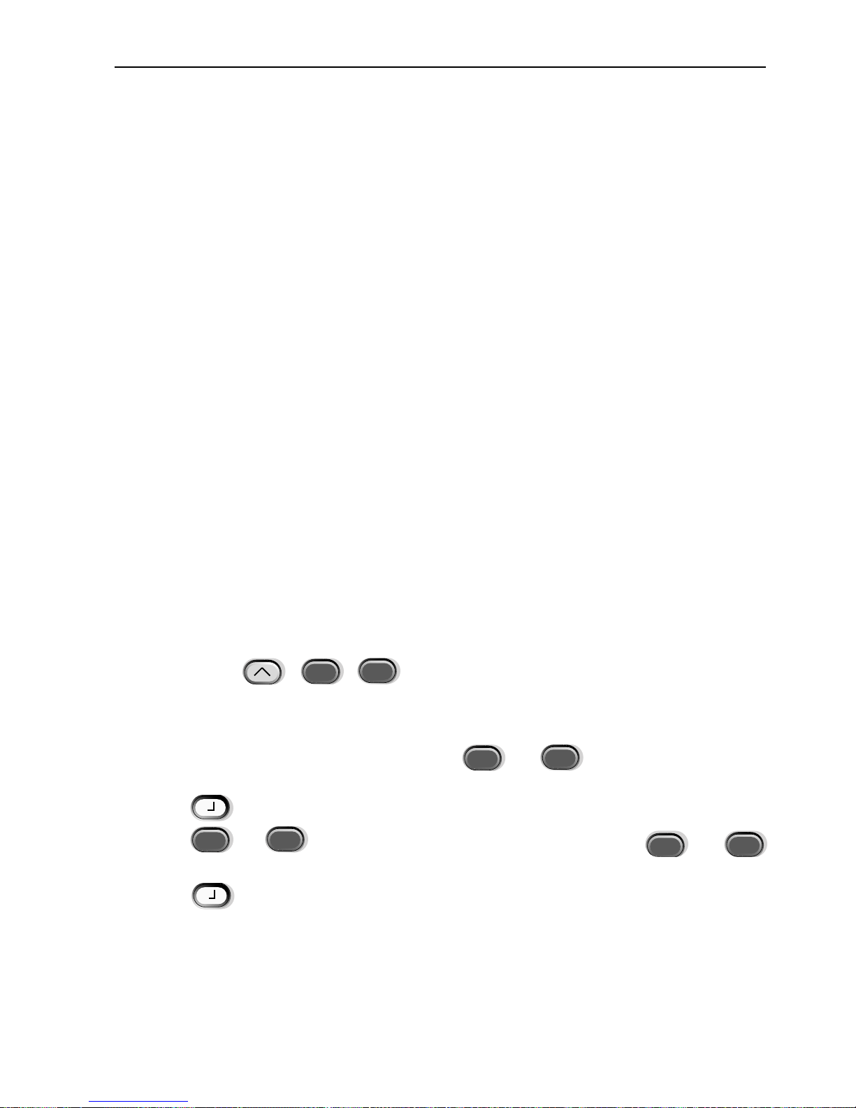
Starts embroidering (sometimes referred to as the start button). It is also used to execute selected functions in the Function menu.
Stops machine motion. Press twice to enable manual jogs of the rack when you are in
the middle of a design.
Used to “frame forward” or “frame backward” in idle or in the FRAME menu. Holding
the key will cause the machine to frame one stitch at a time; release the key to stop
framing. Holding the key for 10 seconds starts the auto-frame function; once the autoframe function has started, you must press to stop framing.
Emergency Stop (Bright yellow with a red center); stops all sewing motion immediately.
To reset, pull or twist slightly and the button snaps back into place.
Pretensioner
Main tensioner
Make sure you
insert the
thread through
the pigtail.
Page 31

Keypad 2-7
11817 Rev. A 2. Operation
Hotkeys
Moves from one menu to the next. After the last menu displays, it wraps back to the
first menu.
Never used alone. It is held down while pressing an additional key, allowing the other
key to take on an alternate function.
▲
Makes a selection. It is similar to clicking the OK button in Windows or pressing the
[ENTER] key on your keyboard.
Toggles the hoop carriage speed fast or slow when manually jogging the rack.
▼
Moves the needle position to the right in the embroidery field (hoop moves left). It is
also used to select values for sub-menu options and for manual color changes.
▲
Moves the needle position to the left in the embroidery field (hoop moves right). It is
also used to select values for sub-menu options and for manual color changes.
▲
Moves the needle position back in the embroidery field. It also scrolls up a menu list. It
is also used to change sub-menu values.
▼
Moves the needle position forward in the embroidery field. It also scrolls down a menu
list. It is also used to change sub-menu values.
▼
▲
A color change enable switch; hold down and use the left and right arrow keys to
manually
▲
▼
▼
▲
A rack enable switch; hold down and use the arrow keys to manually jog the rack.
When pressed simultaneously, displays the previous menu.
When pressed simultaneously, exits any sub-menu and displays one of the idle
menus, even when the machine is embroidering.
▲
Toggles between the Main menu and the Service/maintenance menu.
Increases sewing speed by 50 spm (while machine is in operation).
▲
Decreases sewing speed by 50 spm (while machine is in operation).
▼
Toggles to Language Selection from current menu.
▲
▼
▼
▲
Page 32

2-8 The Menus
Operation Manual for the EMT 10T, 10/4, and 10/4T Melco Embroidery Systems
The Menus
The menu structure is divided into two top-level menus, the Main Operator menu and the Service/Maintenance menu. To toggle between these top-level menus press . To enter
any submenu under one of the two top-level menus, press . Following is a list of all the
menus available in each and what commands are available. If your machine is not equipped with
trimmers, you may not see all the menus and commands listed here.
Main Operator Menu
The Main operator menu is the menu the machine defaults to when powered up. All functions
required for embroidering are found in this menu. Eight submenus are in the Main operator menu.
Press to toggle between the Main menu and the Service/Maintenance menu.
Disk Directory Menu
Lists designs on the floppy disk in the EMT Disk Drive. Use or to scroll through
design names. Press to load the design into machine memory.
Design Menu
Lists designs stored in machine memory. Use or to scroll through the design
names. Press to select a design to be sewn. Up to 16 designs (or up to 500K) may be
queued.
Color Menu
Used to setup the color/needle sequence. The following characters are allowed:
1-10 needle number
0 pause at this color change only (does
not move to next color)
– skip this color change
P pause after all color changes
A stop for applique
Run Design Menu
Confirms the selected design and color sequence is ready to be embroidered. Press to
load the design into the job queue (up to 16 designs may be queued—or up to 500K). Press
(the machine will emit several beeps) to start embroidering the design.
▲
▼
▲
▲
▼
▲
▲
Needle position
▲
COLOR
1 : 1 2 3 4 5 6 7 8 9
10 0 - P A
Page 33

The Menus 2-9
Function Menu
All the commands in this menu result in machine motion and multiple beeps. The commands are described below. Press or to view selections.
Go to hoop center?
Forces an X/Y move to the center of the selected hoop. Only allowed if you are not in the middle
of a design. Press to perform function.
Trace design outline?
Traces the outline of the queued design. Press to perform function. Refer to the Trace
part of the Quick Start section for more information.
Trim immediate?
Forces a trim. Press to perform function.
Set home?
Causes the X and Y axis motors to move to home, then return to their starting positions. This
position is defined as home. Press to perform function. Unless an error condition
occurs, this function is performed automatically every time the machine is powered up.
Power Fail rescue?
Power Fail rescue allows you to resume embroidering a design after the machine has a power loss.
A power loss might occur if an error requires turning the power switch OFF and then back ON for
recovery or if a power failure occurs. Follow these steps to regain your position in the design and
continue embroidering.
1. If large garments are installed, remove them from all heads while the power is OFF; if you are
booting from the disk drive, insert the Boot Disk..
2. Turn the power ON. Wait for the machine to download and power up.
3. Scroll through the menus until the display reads FUNCTION MENU.
4. Press . The display reads GOTO HOOP CENTER?.
5. Press or until the display reads GO TO HEADUP.
6. Press ; if you are loading a design from the disk drive, remove the Boot Disk and insert
the Design Disk now.
7. Press or until the display reads POWER FAIL RESCUE.
8. Press . The beam and carriage assemblies will move to find home, then
return to the next to last stitch embroidered before the power failure. This may take
a minute or so if it is a large design.
9. Press to return to the top level menu.
10. Reinstall any large garments that you removed in step 1.
11. Press . The peripheral will resume embroidering.
11817 Rev. A 2. Operation
▲
▼
▲
▲
▲
▲
▼
▼
Page 34

2-10 The Menus
Operation Manual for the EMT 10T, 10/4, and 10/4T Melco Embroidery Systems
Return to origin?
Returns to the start position of a design that has been partially embroidered. Press to perform function.
Return to last stitching position?
Returns to the last stitched position before continuing if manual jog X/Y was used to view the
design. You may use this function if you have manually moved the x or y axis in the middle of a
design. this function will return you to the last position a stitch was sewn.
1. When the machine is stopped (but still in the middle of a design), press along with
any arrow key to move the hoop.
2. Scroll to the Function Menu and press .
3. Press or until the display reads Return to last stitching position?
4. Press ; the machine will return to the llast stitched position in the design.
5. Press to return to the top-level menu.
6. Press to resume embroidering.
Go to stitch?
Allows you to move to a specified stitch number within a design. For example, you may use this
function to move to a certain position in a design that may not have sewn well.
1. From the Function Menu, press or until the display reads: Go to Stitch?,
then press .
2. Use the arrow keys to enter the desired
stitch number (see illustration).
3. Press ; the machine moves to
that stitch.
4. If you were in the middle of a design when you performed this function, press
to return to the top-level menu, and press to resume embroidering.
Go to color change?
Allows you to move to a specified color change number within a design. For example, you may
use this function to move to a certain color in a design that may not have sewn well.
1. From the Function Menu, press
or until the display
reads: Go to Color Change?, then
press .
2. Use the arrow keys to enter the desired
color change number (see illustration).
Press or to change a character
Press or to change the cursor
position
▲
▼
▲
▼
Press or to change a character
Press or to change the cursor
position
▲
▼
▲
▼
▲
▼
▼
▲
▲
▲
▲
▼
▲
▲
▼
▲
▲
▲
▼
▲
ENTER STITCH NUMBER
0 0 0 0 0
ENTER COLOR CHANGE NUMBER
0 0 0
Page 35

The Menus 2-11
11817 Rev. A 2. Operation
3. Press ; the machine moves to that color change.
4. If you were in the middle of a design when you performed this function, press
to return to the top-level menu, and press to resume embroidering.
Go to headup?
Forces a move to the headup position, ready to sew. Press to perform function.
Options Menu
Used to set all machine options. Press or to view the selections. Use or
to select submenu options. All options are stored in machine memory until changed manually or
until a hard reset is performed.
Select hoop:
Lists all defined hoops. The hoops will appear in the units you select during configuration (i.e.,
English or Metric). Remember when selecting your hoop to select the correct type and size. The
list of defined hoops follows:
• 11.8" X 17.3" (30 X 44cm) Tube
• 11.8" X 14.2" (30 X 36cm) Tube
• 8.3" (21cm) Tube
• 7.1" (18cm) Tube
• 5.9" (15cm) Tube
• 4.7" (12cm) Tube
• 8.3" (21cm) Round (this is a wood frame)
• 7.1" (18cm) Spider
• 5.9" (15cm) Spider
• 4.7" (12cm) Spider
• 3.5" (9cm) Spider
• 2.8" (7cm) Spider
• Sock hoop
• 2.8" X 5.6" (7 X 14.2cm) Large cap frame
• 2.5" X 5.6" (6.3 X 14.2cm) Small cap frame
• 2.8" X 14.3" (7 X 36.2cm) Wide-angle cap frame
• Sash Frame
▲
▼
▲
▼
▲
Page 36

2-12 The Menus
Operation Manual for the EMT 10T, 10/4, and 10/4T Melco Embroidery Systems
Orientation option:
Select from eight different design orientations
represented by the letter F (illustrated at right).
Used to turn a design within a hoop (e.g., for
caps, you would change the orientation).
Trim jump count:
Forces a trim function when consecutive jump stitches or needle ups equal or exceed the number
entered here. The range is 0-20, with 0 disabling the option. The default value is 8. If you enter a
trim value of 1 or 2, the peripheral will trim between letters of an alphabet.
Turbo mode:
When disabled, the machine uses a reduced speed-to-stitch table, resulting in higher embroidery
quality, but slower embroidery speed. Enabled is the default. The maximum embroidery speed is
fastest when Turbo mode is enabled.
Center design:
Allows the design to be centered with respect to the start point. Enabled is the default.
Disk design format:
Selects the format of a floppy disk when loading designs from a disk. Options are DOS, TAJIMA,
BARUDAN FMC, BARUDAN FDR, ZSK, and NO FORMAT. You must choose the format in order to
load a design. The NO FORMAT option will remove the Directory menu from the menu tree. This
saves keystrokes if you never load designs from the disk drive. Select a format other than NO
FORMAT to make the Directory menu re-appear.
Frame Menu
Selects the frame forward or frame backward function. Change by pressing or .
Reset Menu
Clear design
Clears the current design from the queue (does not delete the design from memory). Press
to perform function.
Note: If you started to perform a Move Command, but decided not to move, you must perform
a Clear Design command to continue.
Hard reset
Resets all operator selectable options to the default values, clears the current design from the
queue. Press to perform function.
Service/Maintenance Menu
Contains all service and maintenance functions. Eleven submenus are in the Service/maintenance menu.
Press to toggle between the Service/Maintenance menu and the Main menu.
▲
▲
▲
▼
Page 37

The Menus 2-13
11817 Rev. A 2. Operation
Head Timing Menu
Use the keystroke guide below to move to each position. Refer to the Hook timing section
of Chapter 4 for more information. The Z position (in degrees) will be displayed after each
function.
Go to headup
Forces the z axis to make one plus rotation and stop with needle in up position.
One revolution
Forces z axis to move to headup position with needle in down position.
Needle depth
Must be done after One revolution command to insure the z axis is at its proper position.
Hook timing
Must be done after Needle depth command to insure the z axis is in its proper position.
Top dead center
Must be done after Needle depth command to insure the z axis is in its proper position. Used to
set upper dead stop position.
1 degree forward
Forces z axis to move forward one degree.
10 degrees forward
Forces z axis to move forward ten degrees.
1 degree back
Forces z axis to move back one degrees.
10 degrees back
Forces z axis to move backwards ten degrees.
Z position
Releases the z axis to allow manual rotation with current z position display in degrees. Press
twice to exit Z position and lock Z axis.
▲
▼
▲
▼
▲
▼
▲
▼
▼
▲
▲
▲
Page 38

2-14 The Menus
Operation Manual for the EMT 10T, 10/4, and 10/4T Melco Embroidery Systems
4 Hr Lubrication Menu
Go to this menu when the message time to oil hook appears. This menu forces the machine to
move the hook to its proper position for oiling. Refer to the Lubrication section of Chapter 4 for
the proper place to apply lubricant.
8 Hr Lubrication Menu
Go to this menu when the message 8hr maintenance due appears. This menu forces the
machine to move to the proper positions for oiling. Refer to the Lubrication section of Chapter 4
for the proper place to apply lubricant.
40 Hr Lubrication Menu
Go to this menu when the message 40hr maintenance due appears. This menu forces the
machine to move to the proper position for oiling. Refer to the Lubrication section of Chapter 4
for the proper place to apply lubricant.
80 Hr Lubrication Menu
Go to this menu when the message 80hr maintenance due appears. This menu forces the
machine to move to the proper positions for oiling. Refer to the Lubrication section of Chapter 4
for the proper place to apply lubricant.
480 Hr Lubrication Menu
Go to this menu when the message 480hr maintenance due appears. This menu forces the
machine to move to the proper positions for oiling. Refer to the Lubrication section of Chapter 4
for the proper place to apply lubricant.
2100 Hr Lubrication Menu
Go to this menu when the message 2100hr maintenance due appears. This menu forces the
machine to move to the proper positions for oiling. Refer to the Lubrication section of Chapter 4
for the proper place to apply lubricant.
Page 39

The Menus 2-15
11817 Rev. A 2. Operation
Configuration Menu
This menu allows you to configure certain options. Normally these options are only configured
once, but you may set them as often as you wish. If a hard reset is performed, all these values will
return to their default values. If your periphal is not equipped with trimmers, some of these
menus may not appear. The options follow:
Thread trimmer:
Disables or enables the trimmers. Enabled is the default. Press or to
change.
Trimmer tail length:
Allows a short or long tail length after a trim. Short is the default. Press or
to change.
Trim on stitch length:
The stitch length defined here forces a trim when the next stitch is equal to or greater than the
selected length. The allowable range is 0-127. 0 disables the option. 127 is the default. Press
or to change.
Bobbin detect:
Turns ON or OFF the Under Thread Control
(UTC). ON is the default. On the EMT 10T,
press or to change.
On the EMT 10/4 or 10/4T, refer to the
illustration to the right to turn it on or off
on individual heads. A 0 means the bobbin
detect is turned on for that head, a means it is turned off.
Bobbin detect count:
Allows for selection of consecutive bobbin breaks before machine stops. The allowable range is 0-
50. 0 disables the option. 8 is the default. Press or to change.
Lock stitch:
Forces a lock stitch to be inserted at the beginning of every design and on every restart after a
trim. Enabled is the default. Press or to change.
Accumulate needle ups:
Accumulates consecutive needle ups and converts them into one motion. Enabled is the default.
Press or to change.
Return to design origin at EOD (end of design):
Forces an X/Y motion back to the position at the start of the design if the end point is not the
same. Enabled is the default. Press or to change.
▼▲▼▲▼▲▼▲▼▲▼▲▼▲▼
▲
Press or to change a character
Press or to
change the cursor position
▲
▼
▲
▼
Page 40

2-16 The Menus
Operation Manual for the EMT 10T, 10/4, and 10/4T Melco Embroidery Systems
Start rack motion offset:
Allows a delayed start time of the X/Y rack motion in 5 degree increments depending on different
types of material used. Range is 0-20. 0 is normal movement, and the default. This delayed start
time may produce better embroidery results on delicate fabrics by allowing the needle to come
out of the fabric completely before rack motion occurs. Does not affect sewing speed, instead the
rack moves more quickly. Press or to change.
Unit of measure:
Allows selection of all operator prompts to be in IN (English) or CM (Metric). English is the default.
Press or to change.
Hoop limits:
Turns ON or OFF hoop limits. Default is ON. If you turn the hoop limits OFF, the machine will NOT
beep when it encounters a rack limit during a trace. You are at risk to hit the hoop when Hoop
Limits are turned OFF. Press or to change.
Design filter:
Filters a design when it is downloaded to the machine. Filtering removes all stitches equal to or
less than the selected short stitch length. Jump
stitches and needle ups are changed to normal
stitches if their sum is less than 12.7mm. If their
sum is longer than 12.7mm, they will be divided
into equal jump stitches less than 12.7mm. Refer
to the example illustration to the right. 3 jump
stitches (20 points each) are converted into 1
normal movement. Enabled is the default. Press or to change.
Design filter stitch length:
Determines what short stitch length to use for filtering up to 0.9mm. The allowable range is 0-9
points. It accumulates stitches that are shorter than this value and adds them to the next stitch.
The default is 4 points. Press or to change.
▼▲▼▲▼▲▼▲▼
▲
Page 41

The Menus 2-17
11817 Rev. A 2. Operation
Language selection:
Allows for different languages. Several languages are available.
Inching count:
Selects number of inching stitches (the slow stitches at the beginning of a design and on restart after
a trim or color change) sewn before the machine begins to speed up. These stitches allow the top
thread to catch and hold the bobbin thread. The allowable range is 0-9. Default is 3.
Max Jump Stitch Speed
Selects the maximum speed that jump stitches can be sewn. The range is 400-900 spm; default is
700 spm.
Move Function Menu
Move function
X+00.00 in Y+00.00 in
Forces an X/Y move to a selected distance
from the present position. Press
or to toggle between the X and Y
axis. Press to perform the move.
This is useful to select a position in a hoop that is not the hoop center.
The X and Y coordinates you enter are relative to your current position, NOT to the center of the
hoop.
▲
▼
Press or to change a character
Press or to change the cursor
position
▲
▼
▲
▼
MOVE X/Y X:+00.00IN Y:+00.00IN
Page 42

2-18 The Menus
Operation Manual for the EMT 10T, 10/4, and 10/4T Melco Embroidery Systems
Define custom hoop
Note: Before you attempt to define a new custom hoop, center the 11.8" X 17.3" (30 X
44cm) Tube hoop.
Defines custom hoop sizes based on type of hoop, X/Y dimensions, and hoop center. Press
to start the process. You will be prompted to enter a hoop name (available names are Custom
Hoop 1-8). Use or to change the hoop name. Press to go on.
You will be prompted to choose the type of hoop (available choices are rectangle, cap, oval, and
circle). Press or to select the hoop type. Press to continue.
You will be prompted to choose the X and Y
dimensions (or diameter); refer to the illustration to the right. Press to go
on.
Next you must define your custom hoop’s
center. To do this, measure from the center
of the needle plate to the center of the
hoop in the Y direction. Enter this value to
define the new hoop’s center. Press
to go on.
You will be prompted to save the hoop; press for Yes or for No. Then press
to save the hoop. Your custom hoop will appear in the hoop list in the Options Menu. You
can overwrite a custom hoop, but once you have saved a custom hoop, it will remain in memory
until you reconfigure the peripheral.
Test Mode
Places the machine in test mode, where thread breaks are ignored and the queued design continues to run until is pressed. Must be disabled to return to normal embroidery. This is primarily a service function.
Press or to change a character
Press or to
change the cursor position
▲
▼
▲
▼
▲▲▲
▲
▼
▲
▼
▲▲▲
▲
▼
Y/X LENGTH Y:00.00IN X:00.00IN
Page 43

The Menus 2-19
11817 Rev. A 2. Operation
Diagnostics Menu
The following service diagnostic test are available to run or view:
RSA rev level
Displays the current revision level of the RSA files and the selected machine type.
BIOS rev level
Displays the current revision level of the ROM BIOS.
Motion Controller rev level
Displays the current revision level of the DSP chip set.
FPGA rev level
Displays the FPGA (Field Programmable Gate Array) rev level.
+5 Volt Current
Displays the current supplied by the +5V power supply.
Sew timers
Displays the total accumulated CPU time, and total sew time. The CPU time accumulates when
the machine is turned on, and the sew time accumulates when the machine is embroidering.
Bobbin Control Test
Allows manual testing of the UTC assembly. A beep will sound every time the bobbin sensor is
tripped. Press to start the test; press to stop the test.
Grabber Test
Allows manual testing of the grabber assembly. Press to extend the grabber, and
to retract the grabber.
▲
▼▲▼
Page 44

2-20 Disk Drive
Operation Manual for the EMT 10T, 10/4, and 10/4T Melco Embroidery Systems
Disk Drive
The EMT Disk Drive is a read only disk system allowing the user to embroider EXPANDED designs
in the following formats: DOS 1.44MB, DOS 720K,Tajima, Barudan FMC, Barudan FDR, and ZSK.
The drive does NOT support condensed format designs. The disk drive replaces the need for the
EDS System Controller, thus converting a peripheral into a single embroidery device.
Installing .RSA Files
If the peripheral is part of an EDS or Wilcom System and the network will boot the peripheral, you
must install the .RSA files into the EDS III computer. To install the .RSA files, start Microsoft®Windows®, put the RSA disk into the disk drive, and follow these steps:
1. Click on Start→→Run from the Windows 95 taskbar (or File→→Run from the Windows 3.x Pro-
gram Manager) to display the Run dialog box.
2. Type a:\setup.exe and click Open (or OK if you are using Windows 3.x).
3. Follow the on-screen instructions to install the RSA files.
The operating program or .RSA file for each of the embroidery peripherals that supports the disk
drive will automatically load into the computer.
Note: If you upgrade your RSA files, all parameters are automatically set to their default values.
Configuring The EMT Disk Drive Controlled Unit
If you are operating from an EDS or Wilcom network as well as using the disk drive, install the
correct .RSA files as previously indicated and follow the rules of the network when assigning Unit
names to peripheral devices. Specifically, after setting the Peripheral Program, the Unit name must
be set differently for each peripheral attached to a single EDS System Controller.
If no network is attached to the EMT Disk Drive controlled embroidery peripheral, the Unit name
may be set to any name with 1-16 characters.
Operation
Booting The Peripheral
You may boot one of two ways. If the embroidery peripheral is properly configured and attached
to an EDS or Wilcom System containing the .RSA files, the peripheral will boot from the network
when the peripheral is powered up.
If the peripheral is not connected to an EDS or Wilcom System, or if the system is not turned on
and operating in EDS or Wilcom, the peripheral will boot from the disk drive. A boot disk must be
in the disk drive. If a boot disk is not located in the disk drive, the message: INSERT BOOT DISK
will show on the display. Insert the boot disk and press . After the machine boots
correctly, it will display the model name.
▲
Page 45

Loading a Design 2-21
11817 Rev. A 2. Operation
Loading a Design
Through the Network
After the embroidery peripheral is booted, you may load designs into the embroidery peripheral
buffer. If you are loading designs through the network, please refer to the EDS III Basic manual for
a detailed explanation of sending designs from the computer to the peripheral.
Through the Disk Drive
Once the embroidery peripheral is booted, you may load designs.
Directory Menu
1. Press to display the Directory Menu. If the design format setting in the Options
Menu is correct, proceed to the next step. If the format is not correct, see the “Selecting the
Format” section below before you proceed.
2. Place the diskette with the design to be loaded in the disk drive, then press .
The name of the first design in the directory will show on the peripheral display.
3. To load the design showing on the display, press . If the design name showing on the
display is not the design you wish to load, press or until the desired
design name is showing on the display, then press .
When is pressed, the disk drive light comes on as the design is loaded into the
embroidery peripheral design buffer. While the design is being loaded, the display shows the
name of the design and that it is loading. When loading is complete, the display will show
DESIGN MENU.
Selecting The Format
Options are DOS, TAJIMA, BARUDAN FMC, BARUDAN FDR, ZSK, and NO FORMAT. You must
choose the format in order to load a design. The NO FORMAT option will remove the Directory
menu from the menu tree. This saves keystrokes if you never load designs from the disk drive.
Select a format other than NO FORMAT to make the Directory menu re-appear.
Format Selection
If you need to change the format selection, go into the Options Menu, then press or
to display Floppy disk format. Follow these steps to select a new format:
1. The currently selected format will show on the display. To change the selected format, press
or until the correct format is displayed.
2. When the desired format is displayed, press .
▲
▲
▼
▲
▲
▲
▲
▼
▲
▼
Page 46

2-22 Hooping
Operation Manual for the EMT 10T, 10/4, and 10/4T Melco Embroidery Systems
Hooping
Proper hooping is essential for quality embroidery. The garment or fabric must be taut and flat,
and the weave or knit must be aligned. Follow these basic hooping guidelines to ensure proper
hooping:
• Always hoop on a flat surface
• Use the correct backing
• Use the smallest hoop possible that will accommodate the design within the rack limits (see
the Trace menu for more information).
• Smooth the garment as much as possible before
hooping, including any lining or backing
• Always check the back of the garment after
hooping to make sure there are no wrinkles or
parts which will be inadvertently sewn.
• Do not over-tighten or over-stretch the material
in the hoop
• Be sure the inner hoop does not extend past the outer hoop on the bottom; both rings of
the hoop should be evenly aligned
• Practice
To hoop with a tubular or flat hoop, place the outer hoop on a clean, flat surface. Place the backing down, then the fabric, and then place the inner hoop inside the outer hoop with the mounting brackets facing UP (see Figure 2-8).
Figure 2-8
Mounting brackets
facing UP
(tubular hoop shown here)
Page 47

Quick Start 2-23
11817 Rev. A 2. Operation
Quick Start
The following section outlines the required steps to embroider a design.
Set home
This is normally done on power-up; if the machine detects an error during its test sequence on
power-up, you must correct the error condition (e.g., if the machine is not at HEADUP, you must
GO TO HEADUP), then Set Home.
Press until the display reads FUNCTION MENU, then press . Press
or until the display reads SET HOME. Press .
Select hoop
In the Options Menu, press or until the display reads SELECT HOOP.
Press or to scroll to the proper hoop option. Press to continue.
Select orientation
In the Options Menu, Press or until the display reads Orientation Option. Press
or to scroll through the orientation options. When the desired orientation is dis-
played, press to continue.
Center hoop
In the Function Menu, press or until the display reads GO TO HOOP
CENTER?. Press to center the hoop.
▲
▲
▼
▼
▲
▲▼▲
▼
▲
▼
▲
▼
Page 48

2-24 Quick Start
Operation Manual for the EMT 10T, 10/4, and 10/4T Melco Embroidery Systems
Attach hoop
Tubular hoops attach to the peripheral via the inner frame (see Figure 2-8). This allows the material to hang down around the frame without being sewn together during embroidery. Flat hoops
attach to the peripheral via the outer frame.
Tubular hoops
Refer to the following steps to attach the tubular hoop to the peripheral:
1. Lower the sewing table by lifting the front of the table and pulling it towards you. Place the
table top on the lower table supports (Figure 2-9) and push the table top towards the rear of
the machine. The table top will snap into place.
2. Attach the tubular frame support arms to the proper holes on the X-carriage for the selected hoop.
Use two thumb screws for each support arm (see
Figure 2-10). Make sure the clips (on the ends
where the tubular frame will attach) face UP.
3. Insert the hoop frames by sliding the side brackets
underneath the spring clips on the support arms.
Make sure the slotted bracket (see Figure 2-11) is to
the right (as you are facing the machine). Slide the
hoop towards the rear of the machine until it snaps
into place.
Special note for the EMT 10/4 and 10/4T
You MUST remove all 5 tabletop inserts before embroidering tubular goods on the EMT 10/4 or
10/4T. Failure to do so may result in damage to the equipment or bodily injury. Refer to Chapter 1
for more information.
Figure 2-12
Upper-table
support
Figure 2-13
Figure 2-14
Flat hoop
mounting brack-
et (behind nee-
dle case)
Push the hoop to the right (as you
are facing the machine) then insert
the left side of the hoop
Page 49

Quick Start 2-25
Flat hoops
You can purchase an optional kit to embroider using flat hoops. Flat hoops attach to the peripheral via the outer frame and attach to the peripheral differently than tubular hoops.
Refer to the following steps to attach the flat hoop to
the peripheral:
1. Raise the sewing table by lifting the front of the
table and pulling it towards you. Place the table top
on the upper table supports (Figure 2-12) and push
the table top towards the rear of the machine. The
table top will snap into place.
2. Remove the tubular frame support arms from the
front of the X-carriage. Remove the two thumb
screws holding each support arm (refer to Figure
2-10).
3. Attach the flat hoop adapter bracket to the x-car-
riage using the thumb screws. Make sure the slotted end of the adapter is facing to the right.
4. Along the x-carriage (behind the needle case) are
the mounting locations for the flat hoops. The
mounting brackets on the peripheral are springloaded, so insert the right side (as you are facing
the machine) of the hoop’s bracket first, then push
slightly to the right (to move the spring-loaded
bracket). Insert the left side of the hoop’s bracket
next. Refer to Figures 2-13 and 2-14.
11817 Rev. A 2. Operation
Figure 2-11
Inner frame attaches
to peripheral
Figure 2-9
Lower table
support
Figure 2-10
Thumb screws
Slotted bracket
Page 50

2-26 Quick Start
Operation Manual for the EMT 10T, 10/4, and 10/4T Melco Embroidery Systems
Select a design
To select a design after it has been sent to the peripheral, press until the display scrolls to
DESIGN MENU. Press and the first design is displayed. Use to scroll forward or
to scroll backward through the designs in the buffer. Scroll through the menu until you
reach the design you want. The LCD displays the name of the design, the stitch count, the number of colors in the design, and the current orientation that is selected. Press to select
the design; the LCD displays the next menu.
Color Menu
To set the color sequence press until the display shows COLOR MENU, then press
. Press to move to the next
number and to move back. Press
or to change the needle
position. Press to select the
color sequence; the LCD displays the next
menu.
Press to insert a color sequence and to delete a color
sequence.
Available color choices:
• 1-10 = needle number
• 0 = pause for this color change only
• – = skip this color change
• P = pause at this color change and all color changes thereafter.
• A = stop for applique
Run Menu
Press to queue the design; the LCD displays the next idle menu.
Trace the Design
Note: Do NOT pull the needle or presser foot down to trace.
Press until the display reads: FUNCTION MENU, then press . Press
or until the display shows Trace design outline?, then press . The
LCD will display Calculating design outline. When the outline is calculated, it will display Trace Design name and show you the needle number. Press to initiate
the trace function and the pantograph will begin to move. The hoop moves along the outline of
the design without embroidering. The machine beeps and displays Rack Limit if a rack limit is
encountered. The beep means the needle will strike the hoop if sewn. To correct this, recenter the hoop, select and use a larger hoop, or manually jog the hoop into position. Perform
another trace after you have corrected the problem.
▲
▲
▼
▲
▲
▲
▼
▲▼▲
▲
▼
▲
Needle position
▲
▲
▲
▼
COLOR
1 : 1 2 3 4 5 6 7 8 9
10 0 - P A
Page 51

Quick Start 2-27
Start Embroidering
After the tracing function is finished, press to return to the idle menu
again. Press and the machine will move to the beginning of the design. Press
again and the peripheral will embroider the design selected (you may have
to press an additional time if the design began with a Needle Ups command). The embroidery will stop when the job is complete and the display reads: END OF
DESIGN. To stop the embroidery process before the design is complete, press
on the keypad. To continue after a stop or thread break repair, press again.
Embroidery Speed
While the design is being embroidered you may change the speed of the machine by pressing
or .
Idle Display
While the machine is operating, you may press at any time to see the Idle
display. There are two screens available in the Idle display; press to toggle between
them.
The first display (Figure2-15) shows the
design name, the current sewing speed, the
current orientation, and the current needle
number.
The second display (Figure 2-16) shows the
stitch count, the selected sewing speed, the
needle number, and the percent complete.
11817 Rev. A 2. Operation
▲
▼
▲
Figure 2-15
Figure 2-16
▲
▲
Page 52

2-28 Quick Start
Operation Manual for the EMT 10T, 10/4, and 10/4T Melco Embroidery Systems
Page 53

Standard Cap Frames 3-1
11817 Rev. A 3. Accessories
3.Accessories
Standard Cap Frames
Because a cap is not flat, it cannot be hooped in a flat hoop. To solve this problem, a special
device called a cap frame has been created to hoop caps. There are two sizes of cap frames:
7.0cm X 14.2cm (Large) and 6.3cm X 14.2cm (Small).
There are three parts to a cap frame:
• The cap hoop
• The cap frame driver
• The cap frame gauge
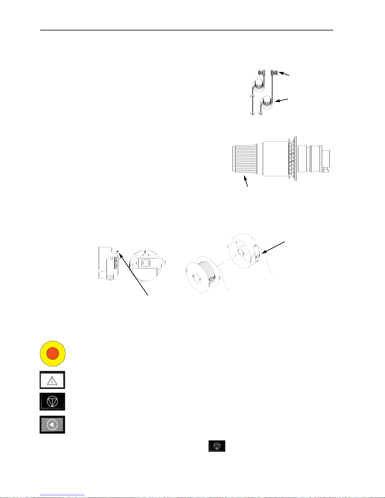
Installing the Standard Cap Frame Driver
Follow these steps and consult Figures 3-1 and 3-2 to attach the cap frame.
1. Lower the tabletop to gain
access to the cap frame
mounting brackets under the
head.
Special note for the EMT 10/4
and 10/4T
You MUST remove all 5 tabletop
inserts before embroidering caps
on the EMT 10/4 or 10/4T. Failure to do so may result in damage to the equipment or bodily
injury. Refer to Chapter 1 for
more information. Also, correlate
the number on the driver with
the number on the head to
ensure sew quality.
2. Select the Large or Small cap frame hoop size from the Options Menu.
3. Under the cylinder arm, locate these cap frame mounting brackets:
• The dove-tail bracket under the needle area
• The bracket with a round hole at the rear of the head.
4. Loosen the thumb screw on the rear mounting bracket.
Figure 3-1
Dove-tail mounting bracket
Rear mounting
bracket
Thumb screw
Page 54

3-2 Standard Cap Frames
Operation Manual for the EMT 10T, 10/4, and 10/4T Melco Embroidery Systems
5. Loosen the thumb screw on
the dove tail bracket on cap
frame driver.
6. Pull the cap frame shaft
towards you, and attach the
hoop bracket to the carriage.
It attaches like a flat hoop.
7. Guide the cap frame shaft into
the hole in the rear mounting
bracket. At the same time,
insert the dove-tail bracket
into the dove-tail mount.
8. Push the cap frame shaft into the bracket hole until the silver ring on the shaft touches the
rear mounting bracket.
9. Tighten the thumb screw on the rear bracket.
10. Tighten the thumb screw on the dove-tail bracket.
11. Repeat this procedure for each head on a four-head peripheral.
12. Press to go to the Function menu then press ; select Go to Hoop Cen-
ter? and press to center the hoop.
First time adjustment
The first time you install the standard cap frame driver(s), you must adjust them to your peripheral
to ensure sew quality. Follow these steps to adjust the driver(s).
1. Install the drive(s) onto the head(s), if you have not.
2. Loosen the four button-head screws across the top
of the drive bracket (see Figure 3-3).
3. Move the beam numerous times to the left and right
extremes (x direction) to align the guide bar in the
ring drive slot.
4. Once the guide bar is aligned, move the beam so
that one of the screws is aligned with the needle
plate. Tighten this screw slightly.
5. Repeat step 4 for the remaining three screws.
6. Move the beam to the left and right extremes one
time. Repeat step 4 again, but this time, tighten the screws fully.
Figure 3-2
Side view
Front view
Thumb
screw
Dove-tail
bracket
Figure 3-3
▲
Page 55

Standard Cap Frames 3-3
11817 Rev. A 3. Accessories
Using the Cap Hoop Gauge
Because the cap hoop is curved, it is difficult to control on a flat surface. The cap hoop gauge
clamps to a table edge to resolve this problem. Once the gauge is clamped, snap the cap hoop
into it to hoop the cap. Hoop the cap according to the instructions on the next page.
Hooping a Cap
To hoop a cap, follow these steps and see Figure 3-4
1. With the latch on the left side,
open the cap frame and rest the
cover on the arm of the gauge.
2. Remove any cardboard or packing
material from the cap.
3. If the cap has a sweat band, pull it
to the outside. If the cap has a
braided cord, move it to the inside
of the cap.
4. If you are using backing, place it
inside the cap.
5. Slide the cap on the hoop frame so
that:
• The brim of the cap is away
from you
• The front of the cap is up
• The sweat band is under the square retainer at the center of the frame
• The sides of the cap are inside the outer arms of the cap frame
6. Push the cap onto the cap frame until the embroidery field is centered. Since caps come in different styles and sizes, you will have to determine how far forward the cap should be.
7. Hook the wire of the hoop latch over the catch, but do not fasten it.
8. Pull the cap as straight, fold free, and taut as possible.
9. Use your right hand to grasp the cap securely from underneath while fastening the frame
latch with your left hand.
10. Pull the elastic cord of the frame over the brim of the cap to secure it.
11. Snap the hoop out of the frame gauge.
Figure 3-4
Brim holder
Page 56

3-4 Standard Cap Frames
Operation Manual for the EMT 10T, 10/4, and 10/4T Melco Embroidery Systems
12. Install the cap frame on the cap frame driver by aligning the frame and the driver, then snapping the frame slots under the roller clamps on the driver.
13. Repeat this procedure for each head on a four-head peripheral.
Raised needle plates
Raised needle plates improve embroidery quality on caps. When cap frames are attached, the
curve of the frame leaves extra space between the cap and the needle plate. To eliminate the
space and ensure high-quality embroidery, a qualified operator or maintenance person should
install raised needle plates as described below. See Figure 3-5.
Note: When using a raised needle plate, use spacers to raise the presser foot.
1. Remove the two screws attaching the standard needle plate and replace the standard plate
with the raised plate. Use the same screws to attach the raised needle plate. The needle
should be centered in the hole in the raised needle plate.
2. Remove the lower cover on the front of the needle case. It is not necessary to remove any
thread.
3. Using a small flat-bladed screwdriver,
push the standard spacer up to the top
of the presser foot assembly (see Figure
3-5).
4. Shim spacers come in two thicknesses:
0.020" and 0.040". Each shim spacer
has five holes, which will cover half of
the needles in each sewing head. The
raised needle plates are 0.090" higher
than a standard needle plate, so you
should add two 0.040" spacers to both
sides of each sewing head (needles 1-
10).
Figure 3-5
Add the extra spacers
beneath the standard shims.
Lower cover
Page 57

Standard Cap Frames 3-5
11817 Rev. A 3. Accessories
5. The spacers must be cut on one side with a pair of
scissors prior to installation. Refer to Figure 3-6 for
the correct areas to cut.
6. Slide the spacer (with the cut side facing upward)
in between the presser feet and the needle bars .
Use a small flat-bladed screwdriver to push the
spacer over the needle bars.
7. Press from the Main menu and the
display shows: HEAD TIMING MENU.
8. Press and the display shows: HEAD TIMING ON.
9. Press . The machine rotates to the “Head up” position and the display
shows: ONE REVOLUTION 110.0.
10. Press . The head rotates to NEEDLE DEPTH. The presser foot should be 0.040"
from the needle plate.
11. Verify the presser foot is clearing the needle plate by 0.030 to 0.050". If needed, add or
remove the necessary combination of the 0.020 or 0.040 spacers to achieve the appropriate
clearance. Go to step #9 to rotate the machine to HEADUP to add or remove spacers.
Note: If you add too many spacers, you may overcompress the presser foot springs and damage
the springs or impair the quality of the embroidery.
12. Replace the lower needle case cover.
13. Repeat for all sewing heads on the EMT 10/4 or 10/4T.
14. Press to exit the Head Timing Menu; then press to return to
the Main menu.
When you return to sewing flat or tubular goods, reverse the above procedure to remove the
raised needle plates and the extra spacers.
Figure 3-6
▲
▲
▼
Page 58

3-6 Wide-Angle Cap Frame
Operation Manual for the EMT 10T, 10/4, and 10/4T Melco Embroidery Systems
Wide-angle cap frame
The Wide-angle cap frame option allows you to embroider on nearly 270° of a cap’s crown and
includes:
• The cap hoop(s)
• The cap frame driver(s)
• The cap frame gauge
First time installation and adjustment
The first time you install the wide-angle cap frame
driver on an EMT peripheral, you must perform the
following adjustment; failure to do so will result in
an excessive wear to the cap frame driver and
reduced embroidery quality.
1. Remove or lower tabletop inserts. On the EMT
10/4 or 10/4T, you only need to remove or lower
the 2 large tabletop sections.
2. Make sure that the cap supports are extended; if
they are not, extend them (refer to the Technical
manual for more information).
3. Make sure that the 3 socket-head cap screws
along the interface bracket (Figure 3-7) and 4
socket-head cap screws which hold the bearing
housing (Figure 3-8) are slightly loose.
4. Move the beam all the way back (towards the
rear of the peripheral) using the peripheral keypad.
5. Install the driver; guide the cap driver shaft into
the hole in the rear mounting
bracket. At the same time,
insert the driver dove-tail support bracket into the female
dove-tail mounting bracket.
Refer to Figure 3-9.
6. Push the cap driver shaft into
the hole in the rear mounting
bracket until it reaches the positive stop.
Figure 3-9
Dove-tail mounting bracket
Rear mounting
bracket
Thumb screw
Figure 3-7
Figure 3-8
Bearing
housing
Screws
Page 59

Wide-Angle Cap Frame 3-7
11817 Rev. A 3. Accessories
Note: When pushing the driver shaft into the hole in
the rear mounting bracket, make sure the cap
supports are positioned over the needle plate.
This prevents the shaft from binding.
7. Tighten the thumb screws on the rear mounting
bracket and on driver dove-tail support bracket (see
Figure 3-10).
8. Position the driver cap supports on the needle plate
(see Figure 3-11), center them to the needle plate
hole and in the same time adjust their position in
up-down direction by moving driver up-down on
the slots in the bearing housing and slightly tighten
at least one socket cap screw on the bearing housing using 4mm hex allen wrench. The cap supports should touch the needle plate lightly and
the driver should slide freely from front to back
without any restriction; the cap supports should
not have any visible side to side movement.
9. Push on the driver bar to move the driver from
front to back several times, making sure the driver moves freely. Tighten all 4 screws on the
bearing housing.
Special note for the EMT 10/4 and 10/4T
Apply the number sticker that is provided to the driver bar and to the head if it wasn’t marked at
the factory. The drivers should always be installed on the same head of the same peripheral they
are adjusted on; when you install the drivers on the peripheral at a later date, make sure the numbers correspond. Repeat steps 2 through 9 for the remaining drivers.
10. Using the peripheral keypad, move the beam to the front of machine and connect the cap dri-
ver to the beam using the two hoop interface thumb screws.
11. Tighten the 3 socket-head cap screws along the interface bracket until they barely contact the
bracket using provided 3mm short arm hex allen wrench. The interface bracket should still be
able to move in up-down direction. Refer to Figure 3-7 for screw locations.
Figure 3-10
Thumb screw
Figure 3-11
Cap
Support
Driver bar
Page 60

3-8 Wide-Angle Cap Frame
Operation Manual for the EMT 10T, 10/4, and 10/4T Melco Embroidery Systems
12. Level the interface bracket. To do this, first
move the beam all the way to the left, by
pushing on the X-carriage. Make sure that
there is no gap between the driver bar and
driver ring (see Figure 3-12). If needed, press
down lightly on the bar and tighten the corresponding socket-head cap screw on the
interface bracket slightly. Then, by pushing on
the X-carriage, move the beam all the way to
the right and repeat the procedure.
13. Repeat moving the driver all the way to right and left, watching closely to ensure that the driver bar firmly contacts the driver ring and moves with no visible restriction. If the driver bar
does not firmly contact the drive ring, loosen the 3 socket-head cap screws and repeat step
14.
14. Carefully and firmly tighten all 3 socket-head cap screws along the interface bracket without
allowing the bracket to move.
15. Repeat steps 11 through 14 for the remaining drivers if necessary.
16. Press to go to the Function menu then press ; select Go to Hoop Center?
and press to center the hoop.
Your wide-angle cap frame driver(s) are fully adjusted and ready for use.
IMPORTANT
If you wish to use the adjusted cap frame option on a different peripheral, check the adjustment
on the new peripheral to ensure proper sew quality.
This adjustment only needs to be performed the first time the cap frame driver is installed on a
machine. The Wide-angle cap frame does NOT require the use of raised needle plates.
Figure 3-12
Driver bar
Driver ring
Check for
contact here
▲
Page 61

Wide-Angle Cap Frame 3-9
11817 Rev. A 3. Accessories
Installing the wide-angle cap frame driver
The steps in this section describe how to install the driver after it has been previously installed and
adjusted. If you have not installed the driver previously, refer to the First Time Installation and
Adjustment section. To install the cap frame driver on an EMT peripheral, follow these steps:
1. Lower the table top to gain access to the cap frame driver mounting brackets under the head.
Special note for the EMT 10/4 and 10/4T
You MUST lower or remove the 2 large tabletop inserts before embroidering caps on the EMT 10/4 or
10/4T. Failure to do so may result in damage to the equipment or bodily injury. Refer to Chapter 1 for
more information. Also, correlate the number on the driver with the number on the head to ensure
sew quality.
2. The Wide-angle cap frame hoop size will be automatically selected.
3. Press to go to the Function menu then press ; select Go to Hoop Center?
and press to center the hoop.
4. Under the cylinder arm, locate
the cap frame mounting brackets (see Figure 3-13):
• The female dove-tail mounting bracket under the needle
area
• The rear mounting bracket
(with a round hole at the
rear of the head)
5. Loosen the thumb screw on the
rear mounting bracket.
6. Loosen the thumb screw on the male dove tail bracket
on cap frame driver (Figure 3-14).
Note: When pushing the driver shaft into the hole in
the rear mounting bracket, make sure the cap
supports are positioned over the needle plate.
This prevents the shaft from binding.
7. Guide the cap driver shaft into the hole in the rear
mounting bracket. At the same time, insert the male
dove-tail bracket into the female dove-tail mounting
bracket.
Figure 3-13
Dove-tail mounting bracket
Rear mounting
bracket
Thumb screw
Figure 3-14
Thumb screw
Driver bar
▲
Page 62

3-10 Wide-Angle Cap Frame
Operation Manual for the EMT 10T, 10/4, and 10/4T Melco Embroidery Systems
8. Connect the wide-angle cap frame driver to the x-carriage using the hoop interface thumb
screws.
9. Push the cap frame driver shaft into the bracket hole as far as possible.
10. Tighten the thumb screw on the rear bracket.
11. Tighten the thumb screw on the male dove-tail bracket.
Note: The first time you install the wide-angle cap frame driver on the peripheral, perform the
adjustment procedure in the previous section.
12. Repeat this procedure for each head on the EMT 10/4 or 10/4T.
Always install the driver on the mounting brackets first, and then attach the driver to the
beam. This will improve the quality of your embroidery.
The tensioner disk
To install the tensioner disk, follow these steps:
1. Loosen the two thumb nuts on the back of
the wide-angle cap frame driver (see Figure
3-15).
2. Insert the tensioner guides into the two
holes in the front of the wide-angle cap
frame driver (through the two thumb nuts
on the rear).
3. Tighten the two thumb nuts.
Figure 3-16 shows an installed tensioner.
Note: You may need to adjust the tensioner
slightly to provide optimal tension for
caps with different crown heights. Simply loosen the thumb nuts and slide the
tensioner to its appropriate location,
then retighten the thumb nuts.
Reverse these steps to remove the tensioner.
Figure 3-15
Thumb nuts
Figure 3-16
Tensioner
Tip
Page 63

Wide-Angle Cap Frame 3-11
11817 Rev. A 3. Accessories
The cap frame gauge
To install the cap frame gauge, tighten the
clamp until the gauge is held firmly. Figure 3-17
shows a mounted cap frame gauge.
Hooping with the wide-angle cap frame
Hooping on a wide-angle cap frame should be as straight-forward and simple as hooping on a
regular cap frame. Follow the steps outlined below to hoop on your wide-angle cap frame:
Figure 3-17
First, attach the cap gauge to a stable
surface.
1
The cap frame has a metal strap, with
a buckle at its end. Make sure this
buckle is attached by screws in its
OUTSIDE two holes, NOT the inside
two holes.
2
Now, slide the cap frame onto the
gauge, making sure the locating element on the cap gauge fits into the
cap frame's notch, and the cap frame
slips firmly under the two roller clips.
3
For the best sew quality, use the rubber strip; it provides appropriate spacing and hoop tension. Drape the strip
over the gauge...
4
...placing the ends BETWEEN these
clip posts and the cap gauge.
5
Appropriate backing can now be
placed around the rubber strip. The
backing stays OUTSIDE the posts and
is pushed BENEATH the locator. You
may use several layers of backing.
6
Page 64

3-12 Wide-Angle Cap Frame
Operation Manual for the EMT 10T, 10/4, and 10/4T Melco Embroidery Systems
Next, prepare the cap for sewing.
Open the back fastener.
7
Lower the sweatband completely.
8
If the cap has a braid, move it around
the cap to the inside and under the
brim as shown.
9
If the braid has a tail on the inside,
trim it short to keep it clear of
embroidery. Leave only about 1/4" of
braid from where it's sewn to the
cap.
10
Now place the cap on the cap frame.
The sweatband should be under the
locator, and the brim should be centered and pointing up.
11
Pull the side of the sweatband
toward the cap frame and down.
12
Flatten any "bunching" of the sweatband by folding it over and toward
the hoop.
13
To secure the sweatband, swing the
metal strap up and over the sweatband and the cap's brim.
14
Close the metal strap, making sure
one band of the strap fits in the
groove on the locator...and the other
band lies cleanly along the brim
edge.
15
Page 65

Wide-Angle Cap Frame 3-13
11817 Rev. A 3. Accessories
To achieve a snug fit of the cap
frame's metal straps, perform step
17 whenever you change cap
styles.
Step 17 does not need to be
performed if the cap style has not
changed. In this case, simply latch
and close the buckle.
16
Loosen the wing nuts on the strap,
latch and close the buckle...then push
down on the strap above the wing
nuts with a hard tool. Use MODERATE pressure when doing this.
Retighten the wing nuts.
17
Pull the elastic brim holders over the
cap's brim to the front. Pull the wrinkles out of the cap using light tension. To secure the cap fabric, attach
two clips...
18
...to each post. The clips are applied
with the handles angled down and
toward the center of the cap.
19
You may now remove the cap hoop
from the gauge. Remember to also
remove the rubber strip. Your cap is
now properly hooped.
20
SPECIAL TIP
Make sure the posts are aligned
properly with the center of the cap
frame.
This is how they should look!
If they look like this, readjust them. If the posts are bent and touching
the cap gauge, bend them back into
position.
±±
±±
Page 66

3-14 Wide-Angle Cap Frame
Operation Manual for the EMT 10T, 10/4, and 10/4T Melco Embroidery Systems
Place the hooped cap on the driver
Unclip the 3 clamps on the cap frame driver (see
Figure 3-18). Slide the frame onto the driver, snapping it into place. Secure the 3 clamps on the driver.
Check the bobbin thread before you install
the frame with a cap attached; if you run
out of bobbin thread you must remove the
cap frame in order to change the bobbin.
This may result in lost registration.
Using the tensioner disk
The tensioner disk attaches to the cap frame driver and increases tension in the crown of the cap
during embroidery. This additional tension helps improve embroidery quality, particularly on nonstructured caps. The tensioner disk also increases embroidery quality on slouch and short-crowned
caps, but because the tensioner disk reduces the embroidery field’s height by approximately 0.23in
(6mm) you may not be able to use the tensioner disk without modifying the design to reduce
overall height.
If you try to use the tensioner disk without compensating for the height of the design, you will
see reduced embroidery quality near the top of the design. The tensioner disk will contact the
needle plate and prevent the beam from moving as far as is needed for the design height.
The tensioner disk needs to be adjusted differently for each type of cap used on your peripheral. To adjust the tensioner disk, simply loosen
the thumb nuts and slide the tensioner disk in
or out, then retighten the thumb nuts (see Figure 3-19). The disk should push the crown of
the cap out slightly (increasing the tension).
There is not a “rule of adjustment” because of
the variety of caps available today.
Do not adjust the tensioner disk to fit so tightly
that the spring (pushing the disk out) is completely compressed. If you do, the tensioner disk may
restrict the cap’s movement during embroidery, resulting in a loss of registration and reduced
embroidery quality.
Figure 3-18
Clamps
Figure 3-19
Thumb nuts
Tip
Page 67

Sewing field
The height of the sewing field varies on caps because of the variation in crown sizes. You can use
the following formulas to calculate the height of the sewing field for different crown sizes:
Remember, if you are planning to use the tensioner it reduces the embroidery field’s height
by approximately 0.23in (6mm).
Wide-Angle Cap Frame 3-15
11817 Rev. A 3. Accessories
Y=A - 1.18
X=14.25"
Where:
Y= height of the sewing field in inches
A=height of the crown in inches
Y=A - 30
X=362mm
Where:
Y= height of the sewing field in millimeters
A=height of the crown in millimeters
Tip
Page 68

3-16 Wide-Angle Cap Frame
Operation Manual for the EMT 10T, 10/4, and 10/4T Melco Embroidery Systems
Cap designs
Designs that embroider well on flats may not embroider as well on caps because of the uneven
tension a cap frame provides. Here are some ideas to help improve embroidery quality on your
wide-angle cap frame:
• To help eliminate slippage, digitize from the center out; start in the center of the design
and embroider one side of the cap then return to the center and embroider the other.
• Complete entire design elements as you go around the side; for example, if you have let-
tering with shading, embroider a letter, then its shading, then move on. This helps to eliminate the push-pull tendency of the fabric of the cap. Underlays should follow this rule,
too.
• If you have a lot of running stitches in a design, consider converting them to satin stitches.
Running stitches have a tendency to lose registration.
• With large designs, try to alter nate the direction of the stitches. This helps to eliminate the
push-pull tendency of the fabric of the cap.
• Use more underlay stitches to help stabilize the design and prevent distortion. Six panel
caps need more underlay in the center where the seam is.
• Using a fusible non-woven backing on six panel caps helps hold the two front panels firm-
ly together.
Modifying your designs to embroider on caps may give you more trims and color changes, but it
will also provide you with much better embroidery quality.
Page 69

The Sash Frame 3-17
The Sash Frame
The sash frame is an aluminum rectangle that attaches across the full length of the x-carriage,
using the table tops for support. The material is held in place by fabric clips included with the sash
frame. The sash frame has a maximum embroidery field per head of 11.02" x 16" (28cm x
40.6cm) for the EMT 10/4 or 10/4T and 11.02" x 19.69" (28cm x 50cm) for the EMT 10T.
Often, only the backing material is hooped in the sash frame, and several smaller pieces of fabric
are fixed on top of the backing with a non-permanent fabric adhesive. This procedure reduces
hooping time and permits a high rate of production on parts of preassembled garments like
labels, patches, collars, and pockets.
Installing the Sash Frame
Follow these instructions and see Figure 3-20.
1. Before installing the sash frame, make sure the table tops are in place. Without the sup-
port of the table tops, the sash frame may be damaged.
2. Guide the sash frame under the head(s) with the mounting holes toward the x-carriage.
3. Match the sash frame mounting holes with the holes on the x-carriage and insert the thumb
screws into the corresponding holes on the x-carriage.
4. Tighten the screws when they are all in place.
11817 Rev. A 3. Accessories
Figure 3-20
Mounting holes
(Sash Frame for the EMT 10/4 shown)
Page 70

3-18 The Sash Frame
Operation Manual for the EMT 10T, 10/4, and 10/4T Melco Embroidery Systems
Storing the Sash Frame
The sash frame will not operate properly if it is bent. Suspend the frame lengthwise when not in
use.
Hoop Selection
Before embroidering with the sash frame, Select Hoop in the Options Menu to either the sash
frame or a spider hoop (if appropriate). Failure to do so may damage the peripheral.
Hooping on the Sash Frame
The same hooping guidelines apply to the sash frame as to regular hooping.
1. Lay the fabric over the sash frame as flat as possible.
2. Attach the first clip on the x-carriage side of the frame near a corner. The thumb rail should
be facing away from the embroidery field.
3. Attach 6 of the 300cm clips along the back of the frame on the EMT 10/4 or 10/4T; use 1220cm clip and 1-300cm clip along the back of the frame on the EMT 10T.
4. Pull the fabric taut and attach the same number of clips at the front of the frame.
5. Attach one 220cm clip to each end of the frame on the EMT 10/4 or 10/4T and one 220cm
clip to each end of the frame on the EMT 10T.
Spider Hoops
A spider is a hoop that holds another hoop. Spider hoops attach to the peripheral and allow garments to be hooped individually without removing the frame. The outermost hoop has brackets
that attach to the beam
There are two spider hoop options available. One option attaches to the sash frame, and one
option attaches to the peripheral the same way a flat hoop does.
Page 71

The Sash Frame 3-19
To install spider hoops on the sash frame:
1. Attach the thumb screws for the spider hoop into the sash frame, but do not tighten yet.
2. Remove the inner hoop from the 21cm hoop with the two brackets (shown in Figure 3-21).
3. Insert the spider hoop you plan to use so that the opening in the spider for the hoop tightener
is centered on the bracket with the back-facing slot (Bracket A in Figure 3-21). Secure the spider with the 21cm hoop tightener.
4. Referring to Figure 3-21, slide bracket A into place on the thumb screw at the rear of the sash
frame, then swing bracket B into place on the thumb screw at the front of the sash frame.
5. Tighten the thumb screws.
6. Repeat for all embroidery heads on the EMT 10/4 or 10/4T.
Note: After using the spider hoops and BEFORE embroidering with the full sash frame
(no spider hoops attached) remove the thumb screws or the machine may be
damaged.
11817 Rev. A 3. Accessories
Figure 3-21
Opening for the
hoop tightener
Bracket A
Bracket B
21cm hoop tightener
Page 72

3-20 Lamps
Operation Manual for the EMT 10T, 10/4, and 10/4T Melco Embroidery Systems
Lamps
EMT 10T
The EMT 10 comes with a flexible lamp attached to
the table. The lamp has a separate ON/OFF switch
located on the bulb case (Figure 3-22). Push to turn
the lamp ON or OFF.
To change the bulb, turn the power off, then
unscrew the bulb case (refer to Figure 3-22). Use a
replacement bulb from Melco (one is provided in the
operator kit).
EMT 10/4 or 10/4T
The EMT 10/4 has built-in fluorescent lights above
the table. The lights have a separate ON/OFF switch
located next to the main power switch (see Figure 3-
23). Push to turn the lamp ON or OFF.
To change the bulb, turn the power off, twist the old
bulb slightly, then remove. Align the contacts on the
new bulb with the contacts on the machine. Insert
the new bulb and twist into place. Use a 3’ 25W fluorescent bulb (Melco part number 010394-01).
Figure 3-22
Figure 3-23
ON/OFF
switch
Light
switch
Power
switch
Page 73

Bobbin Winder 3-21
Bobbin Winder
The Bobbin Winder is available in two basic configurations: as a built in feature of the EMT 10T
and as a stand-alone option. See Figures 3-24 and 3-25.
Thread Selection
Although all standard embroidery threads may be used as an under or bobbin thread, embroidery
results vary depending on the thread weight and composition selected. Thin, weak threads will
increase thread breakage problems. Conversely, thick, slick-finish threads may produce problems
with the stitch quality of finished embroidery. Bobbin tension requires adjustment for good
embroidery with any thread. The weight of the thread selected and the tension used when winding will also determine the amount of thread on the bobbin and therefore the frequency of bobbin changes. For most applications, a cotton thread or a core spun cotton composition thread
(such as RASANT) in a 40 or 50 weight (DTEX numbers 135x2 and 128x2 respectively) is recommended.
Operation
1. Thread the winder as shown in
Figure 3-26. The arrows on the
base plate indicate the direction
of the thread path.
11817 Rev. A 3. Accessories
Figure 3-24 Figure 3-25
Figure 3-26
Stand-alone
bobbin
winder
Built-in
bobbin winder
Page 74

3-22 Bobbin Winder
Operation Manual for the EMT 10T, 10/4, and 10/4T Melco Embroidery Systems
2. Place an empty bobbin spool (P/N 008499-01) on the winder shaft and make 6-8 tight wraps
of thread around the spool in the direction shown. Break or trim off the thread tail close to
the spool.
3. Move the actuator lever to the ON position
(see Figure 3-27) and winding will begin. The
winder automatically stops when the bobbin
is wound completely.
Note: To set the level of fill, adjust the position
of the Bobbin Full switch on the actuator
lever using the two screws on top of the
lever. The level of fill should be set to
approximately 80% of the bobbin capacity or about 0.04" [1mm] below the edge
of the spool flange.
4. Move the actuator lever to the OFF position,
remove the wound bobbin and break or trim
the thread tail.
A properly wound bobbin is shown in Figure 3-28 (item A). Items B through E in Figure 3-28 show
improperly wound bobbins. Adjust the winder tension, the thread path or the Bobbin Full switch
to correct winder operation if you are experiencing any of the situations shown below.
Figure 3-28
Figure 3-27
Actuator lever
Move in the direction indicated
Page 75

Bobbin Winder 3-23
Motor Protection
The bobbin winder motor is equipped with a
thermal switch to protect the motor and drive circuitry in the event of an overload condition. If the
bobbin winder stops due to an overload follow
these steps to correct the problem:
1. Move the actuator lever to the OFF position.
2. Clear the obstruction and lubricate the drive
shaft (refer to Figure 3-29).
3. When the motor cools, the thermal switch
will automatically reset.
4. Move the actuator lever to the ON position to
resume operation.
Bobbins
The bobbin winder is designed for use with the aluminum bobbin spool (p/n 008499-01) provided
with the unit. If bobbin spools from other sources are used, the bobbin may be improperly
retained on the bobbin winder shaft. Most nonstandard bobbin spools have a slot in the spool
hub that engages the bobbin winder shaft spring
and holds the bobbin in place. If this type of bobbin spool is used, you must reposition the shaft
spring. Refer to Figure 3-30 and follow the steps
below:
1. Use a needle to disengage the spring from
the standard (upper) hole in the shaft.
2. Slide the spring into the shaft until the spring
tail snaps into the second (lower) retaining
hole.
3. This is the operating position for slotted hub
bobbin spools.
11817 Rev. A 3. Accessories
Figure 3-29
Figure 3-30
Oil here
Lower hole
Upper
hole
Page 76

3-24 Bobbin Winder
Operation Manual for the EMT 10T, 10/4, and 10/4T Melco Embroidery Systems
Bobbin Winder Maintenance
When the bobbin winder is subjected to heavy or
continuous operation, you may need to lubricate
the bobbin winder shaft. Apply one drop of
sewing machine oil to the bobbin winder shaft as
shown in Figure 3-31. Rotate the bobbin winder
shaft by hand until the shaft moves smoothly and
freely.
Figure 3-31
Oil here
Page 77

Maintenance 4-1
4.Operator Maintenance
This chapter outlines machine maintenance; in addition, operators and maintenance personnel
must attend a Melco approved training course prior to maintaining the machine.
Installing a Needle
Each needle has a needle clamp set screw holding it in place as shown in Figure 4-1. Use the
small flat-blade screw driver from the tool kit
and follow these steps to replace a needle:
1. Turn the set screw counterclockwise until
the needle can slide down and out of the
needle bar. Do not remove the set screw.
2. With the scarf of the new needle toward
the rear of the head, slide the needle into
the needle bar as far as it will go, and retighten the set screw. The eye of the needle
should be facing directly forward.
Thread Break Switch
Each head has a thread break switch below the tensioners with
(ON), (AUTO), and (OFF) positions (see Figure
4-2). The switch controls whether the individual head stitches as
it moves through a design. The table below summarizes the
functions of the switch.
11817 Rev. A 4. Operator Maintenance
Figure 4-1
Figure 4-2
SETTING
FUNCTION
Sews during thread break and framing
recovery. Use to restitch an area.
Only heads with thread breaks will sew
during thread break recovery or framing.
Should be used for normal operation.
Disables the sewing head.
Page 78

4-2 Maintenance
Operation Manual for the EMT 10T, 10/4, and 10/4T Melco Embroidery Systems
Thread Break Indicator LED
Next to each Thread Break Switch is an LED that signals a thread break (refer to Figure 4-2). When
a thread break is detected, the LED on that head will be illuminated. A blinking LED indicates an
under-thread break while a steadily glowing LED indicates an upper-thread break.
Cleaning
Work area
The work area around your peripheral should be kept orderly and clutter-free at all times.
Exterior Surfaces
Clean outer plastic surfaces once per month with a soft, clean cloth, a mild detergent and water.
Wring out the cloth before wiping the surfaces. Do not get water or any other fluids inside the
machine or on any of the working mechanical surfaces.
Note: If an accidental spill occurs, wipe it up immediately with a clean dry cloth and allow the
machine to dry completely before turning the power on.
The Rotary Hook Area
1. Clean this area once per month with the machine power OFF.
2. Remove the 2 needle plate screws and lift off the needle plate.
3. Clean the exposed area with the brush supplied in the operator kit, or use compressed air to
blow any debris from the area.
Note: Depending on the type of material being used, this area may require cleaning more often.
Some high-lint materials will require this area to be cleaned once per day for peak performance.
Page 79

Lubrication 4-3
11817 Rev. A 4. Operator Maintenance
Lubrication
The EMT 10T, 10/4, and 10/4T require regular maintenance to perform their best. A message will
display at the end of each design when it is time for maintenance. Press to
enter the Service/Maintenance menus (HEAD TIMING MENU will be displayed). Press
to scroll to the required menu to perform the maintenance. Any necessary tools are provided in
the operator kit. You can use a light-duty sewing oil (available from Accessory Resource Corporation) to lubricate your peripheral; a small bottle is provided in the operator kit.
Note: Before you perform any lubrication on the peripheral, you should remove all garments
from the machine. Also, for every lubrication menu except the 8 hour menu you should
remove the hoops; the eight hour menu moves the cap frame driver to distribute the oil,
so it must be attached to the peripheral. And because the maintenance program requires
rack movement in most menus, your current start position will be lost.
Press to step through the menu. Each time you press , the machine will move to its
next position. Refer to these pages to oil each component throughout the process. When you
have completely stepped through each menu, the display will be cleared.
The message will display at the end of each design. You can press any key to temporarily clear the
message, but you must perform the required maintenance to clear the message (until the maintenance is required again). Use the oil provided in the operator kit.
Due to software limitations, you may experience multiple lubrication messages for different lubrication intervals. For example, you may perform the 40 hour maintenance, sew a design, and have
to perform the 80 hour maintenance. The reason for this is that the counter, which logs the time
for each message, is not reset until you perform the maintenance.
Refer to this section for lubrication information. Follow the steps outlined below for each message.
Time to oil hook
When this message appears, go into the 4
hour lubrication menu and press .
When hook appears, press . This
causes the z axis to move the hook to its proper position for oiling (250°). Refer to Figure 4-3
to lubricate the hook. Press when
done.
You must perform this operation to clear the
message.
▲
▲
Figure 4-3
▲▲▲
Put 1 drop of oil
on as shown
Page 80

Operation Manual for the EMT 10T, 10/4, and 10/4T Melco Embroidery Systems
4-4 Lubrication
8hr maintenance due
This time will only accumulate when a cap frame is in use. You must perform this operation to
clear the message. You may leave the driver attached to the peripheral to perform these maintenance steps.
If you are using a Large or Small Cap Frame,
go into the 8 hour lubrication menu then
press . Press or until
cap driver shaft appears, then press .
This causes the y axis beam to move the cap
frame to the correct position for oiling. Use 1
drop of oil on each side of the shaft (refer to
Figure 4-4 to lubricate the cap frame driver
shaft). Press when done. The y-rail
will move back and forth to distribute the oil.
If you are using a Wide-Angle Cap Frame, go
into the 8 hour lubrication menu then press
. Press or until wide-
angle driver shaft guide appears, then press
; the x-carriage will move to the front.
Wipe the lint off both driver shafts (see Figure
4-5). Place one drop of oil on the Driver shaft
guide (the bottom shaft) as close to the cap
frame driver as possible, then press to
move the x-carriage to the rear. Wipe the lint
off both shafts. Place one drop of oil on the driver shaft guide at the plastic pad (see Figure 4-
6). Press when done. The x-carriage will move back and forth to distribute the
oil.
Figure 4-4
▲▲▲
Figure 4-5
Figure 4-6
Driver
shaft guide
Plas-
tic
▲▲▲
▲▼▲
▼
▲
Wipe the lint
off both shafts
Page 81

11817 Rev. A 4. Operator Maintenance
Lubrication 4-5
40hr maintenance due
When this message appears, go into the 40
hour lubrication menu, then press
When upper connecting rod displays, press
. This moves the needle case to its proper
position for oiling (needle 1 and 180° of z axis).
Figure 4-7 shows the lubrication hole inside the
machine. Insert the oiler through the square hole
next to the red dot on the right side of the head.
Press when done.
You must perform this operation to clear the
message.
80hr maintenance due
When this message appears, go into the 80
hour lubrication menu, then press
Refer to the steps below to lubricate each area.
Note: If you have a cap frame driver attached,
you must remove it before stepping
through this menu.
1. When upper/lower needle bar displays,
press . No motion is required.
Refer to Figure 4-8 to lubricate the upper
and lower needle bars. Lubricate the needle
bars for all ten needles. Press
when done.
▲
Figure 4-7
Put 1-3 drops of
oil here
▲
▲
Put 2-3
drops of oil
here
Put 2-3
drops of oil
here
Figure 4-8
▲
▲
Red dot
Page 82

Operation Manual for the EMT 10T, 10/4, and 10/4T Melco Embroidery Systems
4-6 Lubrication
2. When needle bar driver/v-rail displays,
press . This moves the needle
case to its first position for oiling (needle 1).
Refer to Figure 4-9 to lubricate the needle
bar driver at needle 1. Also refer to Figure 49 to lubricate the v-rail. Put the oil in the vrail as close to the needle case as possible.
To access these areas on the EMT 10/4 or
10/4T, insert the oiler through the hole with
the red bushing on the front of the panel.
Use a flashlight if needed. Press to
move the needle case to needle 10. Oil the
needle bar driver as shown in Figure 4-10.
Also, lubricate the v-rail on this side of the
head. Press when done. The head will
move back and forth to distribute the oil.
Figure 4-9
Top view of needle case
Put 3-5 drops of oil
in this hole
Figure 4-10
Top view of needle case
Put 3-5 drops of
oil in this hole
▲▲▲
Put 1 drop of
oil in the v-rail
Put 1 drop of
oil in the v-rail
Page 83

3. When lower connecting rod displays, press
. This moves the needle case to its
proper position for oiling (needle 10, 150° of
z axis). Refer to Figure 4-11 to lubricate the
lower connecting rod. Use a flashlight if
needed. Press when done.
4. When y-rails is displayed, press
. This moves the y-rail into
its proper position for oiling. Refer to
Figure 4-12 to lubricate the y-rail. Press
when done (the y-rail will
move back and forth to distribute the
oil). The y-rails on the EMT 10T are not
located directly under the slot. you must
angle the oiler slightly toward the middle of the machine to reach the rails.
Figure 4-13 shows the location of the
rails (with the side panel removed).
11817 Rev. A 4. Operator Maintenance
Lubrication 4-7
Figure 4-12
Place 1-2 drops on
both the front and the back
of the y-rail through this
slot. Repeat for the left side
of the machine
▲▲▲
Figure 4-11
Put 3-5 drops
of oil here
▲
Figure 4-13
Red circle
Left side
view
Page 84

Operation Manual for the EMT 10T, 10/4, and 10/4T Melco Embroidery Systems
4-8 Lubrication
5. When moveable frame, knife arm rear pin displays, press . This moves the x/y
axis to hoop center. Remove the rear bed cover (Figure 4-14). Refer to Figure 4-15 to lubricate
the trimmer moveable frame and knife arm rear pin. Press when done. Replace
the rear bed cover.
6. When trimmer knife drive arm, front
pin displays, press . No motion
is required to lubricate the trimmer
knife drive arm and pin. Remove the
needle plate. Refer to Figure 4-16 to
lubricate the trimmer knife drive arm
and pin. Press when done.
Replace the needle plate.
Figure 4-15
Put 1 drop of oil
at all four loca-
tions (moveable
frame)
Top view (with cover
removed)
▲
▲
Figure 4-16
Put 1 drop of
oil on each
location (knife
drive arm)
Top view (with
needle plate
removed)
▲
▲
Put 1 drop of oil
here (front pin)
Rear bed
cover
Figure 4-14
Put 1 drop of oil here
(knife arm rear pin)
Page 85

11817 Rev. A 4. Operator Maintenance
Lubrication 4-9
7. When trimmer picker
base shaft, rod pivot
displays, press .
No motion is required to
lubricate the trimmer picker base shaft and rod
pivot. Refer to Figure 4-17
to lubricate the trimmer
picker base shaft and rod
pivot. Press when
done. The picker will cycle
in and out.
If your peripheral is not equipped with trimmers, you do not have to
perform steps 5, 6, or 7. This completes the 80 hour maintenance.
You must perform ALL operations to clear the message.
480hr maintenance due
When this message appears, go into the 480 hour lubrication
menu, then press . When x axis dis-
plays, press . This causes the x
beam to move to the correct position for oiling.
Before you can oil the x-carriage, you must remove
the aluminum cover; there are 6 screws along the
top of the cover. Remove all 6 screws, then carefully
lift the cover off the x-carriage.
The x-carriage is a metal beam with a groove along
the front and back (along the top edge). When you
oil the x-carriage, make sure you put one drop
of oil in the groove on each side of the metal
beam. Figure 4-18 shows the groove along the
front of the x-carriage; there is another groove on
the back side of this beam.
Refer to Figure 4-19 to lubricate the x-carriage on
an EMT 10T.
Refer to Figure 4-20 to lubricate the x-carriage on
an EMT 10/4 or 10/4T.
Replace the cover on the x-carriage; be careful not
to over-tighten the screws.
Press when done. The x-carriage will move
back and forth to distribute the oil.
Figure 4-17
Put 1 drop
of oil here
(rod pivot)
Put 1 drop of
oil in this hole
(picker base
shaft)
▲
▲
Figure 4-19
▲▲▲
Oil at each
location
Figure 4-20
Oil at each loca-
tion; repeat for the other
side of the beam
Figure 4-18
Page 86

Operation Manual for the EMT 10T, 10/4, and 10/4T Melco Embroidery Systems
4-10 Lubrication
2100hr maintenance due
When this message appears, go into the 2100
hour lubrication menu, then press .
Refer to the steps below to lubricate each
area.
1. When color change cam displays, press
. This causes the needle case to
move to needle 10. Refer to Figure 4-21 to
lubricate the color change cam; USE A
SMALL AMOUNT OF GREASE to lubricate
the color change cam pins. Press
when done (the machine will perform a
series of color changes to distribute the
grease).
2. When take-up lever cam and follower displays, press . This causes the needle case
to move to needle 1 for proper lubrication. Use a cotton swab and a SMALL AMOUNT OF
GREASE to lubricate the take-up lever cam and follower.
Refer to Figure 4-22 to lubricate the takeup lever cam and follower. Use a flashlight
if necessary.
For an EMT 10/4 or 10/4T, you must
remove the end cover to access the cam
on head #1. To do this, remove the 3
screws on the front (see Figure 4-23) and
loosen the 2 screws along the top (see Figure 4-24). You must lubricate the cam on
all 4 heads. Use a flashlight if necessary.
Replace the end cover when finished.
Press when done.
Figure 4-22
▲
▲
Figure 4-21
▲▲▲
Figure 4-24Figure 4-23
Screws
Screws
Page 87

3. If you are using a Wide-Angle Cap Frame,
the message Wide-Angle Driver Shaft will
appear; press . Remove the
wide-angle driver from the peripheral. Wipe
the lint off the driver shaft (see Figure 4-25).
Loosen the 2 screws holding the rear support bracket using the 2mm hex wrench
(see Figure 4-26).
Remove the rear support bracket.
Pull the driver shaft and driver shaft guide
out the front of the driver until the bearings
are exposed (see Figure 4-27).
Place 10 drops of oil on the bearings.
Push the driver shaft and driver shaft guide
up through the bearing housing.
Attach the rear support bracket and tighten
the 2 screws.
Press when done.
You must perform all operations to clear the message.
11817 Rev. A 4. Operator Maintenance
Lubrication 4-11
Figure 4-25
Figure 4-26
Figure 4-27
Dri-
ver
Screw
holes
Open
bearings
▲
▲
Page 88

Operation Manual for the EMT 10T, 10/4, and 10/4T Melco Embroidery Systems
Replacement Parts
Fuses
There are two operator-replaceable fuses. If a fuse must be replaced, use this chart for appropriate
fuse ratings. Do not use a fuse with any rating other than what is listed here:
To replace a fuse, follow these steps:
1. Turn off the power and disconnect the power cord.
2. Directly above where the power cord plugs in is a small
plastic cover (see Figure 4-28). Use your fingernails to
unclip each side of this cover in the locations shown in
Figure 4-28.
3. When the cover is unclipped, pull on the cover to
remove the fuse holder (see Figure 4-29).
4. Change the fuses, then replace the fuse holder.
5. Reconnect the power cord and turn on the power.
Tool Kit
The tool kit contains the following items and is included in the operator’s kit:
4-12 Replacement Parts
PERIPHERAL
115V RATING (Melco part number)
230V RATING (Melco part number)
EMT 10T
5 A (010162-05)
5 A (010162-05)
EMT 10/4
10 A (010162-10)
5 A (010162-05)
EMT 10/4T
10 A (010162-10)
5 A (010162-05)
12-piece standard ball hex set
Right angle screwdriver
1/16” ball allen wrench
Phillips #2 screwdriver
Short straight screwdriver
9/64” ball allen wrench
Straight small screwdriver
Tool handle
5/23 ball allen wrench
Phillips offset screwdriver
Tool extension
6-piece metric ball hex set
Figure 4-28
Plastic cover
Figure 4-29
Page 89

Replacement Parts 4-13
Operator Kit
The contents of the operator’s kit are identical for the EMT 10T, 10/4, and 10/4T except for the
manual sets. Following is a list of all items found in the kit:
11817 Rev. A 4. Operator Maintenance
PART NUMBER
DESCRIPTION
761003-01
OILER
003772-01
NEEDLE, ARC, 80/12R, 10PK, 16 X
761008-01
BRUSH, LINT
006795-01
MONOFILAMENT
861689-01
LUBRICANT, GREASE T517, 2 OZ
001532-01
BAR, NDL
006846-01
KIT, TOOL, UNIVERSAL
007505-01
SHIM, NDL CS
110113-01
WARRANTY, STATEMENT, LIMITED, 12 M
003772-03
NEEDLE, ARC, 80/12FG, 10/PK, 16 X
005577-01
BUMPER, WASHER
001528-01
CLAMP, NDL, ASSY
001537-01
SPRING, HLDING, NDL BAR
007559-01
SPRING, CHECK, TNSNR, THD
007591-01
DAMPER, NDL CLAMP
009027-01
GAGE, COMBINATION, UTC
005917-01
DISK, RSA FILES (2 DISKETTES), ED
005378-01
DISK, RSA FILES, (1 DISKETTE), ED
110191-01
ABOUT YOUR TRAINING
005703-01
TUBE, GUIDE, THD, THD TREE, 9.7
”
011350-01
BULB, REPLACEMENT, FLEX-LITE 12V/12W
Page 90

4-14 Replacement Parts
Operation Manual for the EMT 10T, 10/4, and 10/4T Melco Embroidery Systems
Spare Parts
EMT 10T
To help reduce down-time, Melco suggests keeping certain spare parts on hand for easy replacement and maintenance. Melco provides a Spare Parts kit (p/n 10905); it contains the following
items:
Note: The spare parts kit for older EMT 10Ts (machines that pre-date spring 1998) is part num-
ber 010431-01. It includes the same items as those listed below, but also includes a Fuse
Kit. Confirm your serial number with your Melco Representative to verify which kit is right
or your machine.
PART NUMBER
DESCRIPTION
010369-01
CABLE, ETHERNET, NTWRK, INTFC
10871
PCB, KYBD W/ KEYCAPS, DISPLAY, EMT, ASSY
10711
PCB, CPU, ASSY
009419-01
PCB, MOTOR DRIVER, EMT10, ASSY
009000-01
HOOK, ROTARY, SM BOBBIN
004267-01
CASE, BOBBIN
007924-01
FOOT, PRESSER, ASSY
005617-01
KNIFE, MOVABLE
009411-01
PCB, CLR CHNG, EMT, ASSY
010107-01
UTC, ASSY
344924-01
STRAP, WRIST, STATIC
005600-01
KNIFE, SPRING, FIXED
006671-01
PRESSER UNDER THREAD
008471-01
VELCRO, GRABBER, FLARRED
007505-01
SHIM, NDL, CS
110138-01
LIST, HARDWARE, SPARE
001532-01
BAR, NDL
001840-01
CLAMP, STOP, NDL BAR
003586-01
BLADE, GRABBER
001528-01
CLAMP, STOP, NDL BAR
004643-01
SCREW, NDL PLATE
341992-06
SCREW, FIXING ROTARY HOOK
Page 91

Replacement Parts 4-15
EMT 10/4 or 10/4T
To help reduce down-time, Melco suggests keeping certain spare parts on hand for easy replacement and maintenance. Melco provides 4 Spare Parts kits for the EMT 10/4 and 10/4T:
• p/n 010901-01 contains mechanical items for the EMT 10/4
• p/n 010898-01 contains electrical and mechanical items for the EMT 10/4
• p/n 010900-01 contains mechanical items for the EMT 10/4T
• p/n 010899-01 contains electrical and mechanical items for the EMT 10/4T
11817 Rev. A 4. Operator Maintenance
p/n 010901-01
PART NUMBER
DESCRIPTION
010689-01
CABLE, ETHERNET, NTWRK, INTFC, 50
010107-01
UTC, ASSY
001532-01
BAR, NDL
007924-01
FOOT, PRESSER, ASSY
008490-01
CASE, BOBBIN, SM. W/SPRING
009000-01
HOOK, ROTARY, SM BOBBIN
006520-01
PLATE, NEEDLE, UTC
001840-01
CLAMP, STOP, NDL BAR
003586-01
BLADE, GRABBER
008471-01
VELCRO, GRABBER, FLARRED
001528-01
CLAMP, NDL, ASSY
001828-01
SCREW, SET, NDL CLAMP
005600-01
KNIFE, SPRING, FIXED
006671-01
PRESSER, UNTER THREAD
005617-01
KNIFE, MOVABLE
007505-01
SHIM, NDL CS
110231-01
LIST, HARDWARE, SPARE, 4 HD
004803-01
ASSY, PKNG, SPARE PARTS KIT
010902-01
KIT, FUSE, EMT 10/4(T)
Page 92

4-16 Replacement Parts
Operation Manual for the EMT 10T, 10/4, and 10/4T Melco Embroidery Systems
p/n 010898-01
PART NUMBER
DESCRIPTION
009578-01
PCB, LV DRIVER, ASSY, EMT 10/4
010689-01
CABLE, ETHERNET, NTWRK, INTFC, 50
010280-02
PCB, Y-HOME, ASSY, EMT10/4
010872-06
PCB, CPU, ASSY
344924-01
STRAP, WRIST, STATIC
010107-01
UTC, ASSY
009407-04
PCB, INTFC, ASSY EMT 10
009411-01
PCB, CLR CHNG, EMT, ASSY
001532-01
BAR, NDL
007924-01
FOOT, PRESSER, ASSY
008490-01
CASE, BOBBIN, SM, W/SPRING
009000-01
HOOK, ROTARY, SM BOBBIN
006520-01
PLATE, NEEDLE, UTC
001840-01
CLAMP, STOP, NDL BAR
001528-01
CLAMP, NDL, ASSY
001828-01
SCREW, SET, NDL CLAMP
010027-01
PCB, ESTOP, ASSY, EMT 10/4
10871
PCB, KYBD W/ KEYCAPS, DISPLAY, EMT, ASSY
007505-01
SHIM, NDL CS
110231-01
LIST, HARDWARE, SPARE, 4 HD
004803-01
ASSY, PKNG, SPARE PARTS KIT
010902-01
KIT, FUSE, EMT 10/4(T)
Page 93

Replacement Parts 4-17
11817 Rev. A 4. Operator Maintenance
p/n 010900-01
PART NUMBER
DESCRIPTION
010689-01
CABLE, ETHERNET, NTWRK, INTFC, 50
010107-01
UTC ASSY
001532-01
BAR, NDL
007924-01
FOOT, PRESSER, ASSY
008490-01
CASE, BOBBIN, SM, W/SPRING
009000-01
HOOK, ROTARY, SM BOBBIN
006520-01
PLATE, NEEDLE, UTC
001840-01
CLAMP, STOP, NDL BAR
001528-01
CLAMP, NDL, ASSY
001828-01
SCREW, SET, NDL CLAMP
007505-01
SHIM, NDL CS
110231-01
LILST, HARDWARE, SPARE, 4 HD
004803-01
ASSY, PKNG, SPARE PARTS KIT
010902-01
KIT, FUSE, EMT 10/4(T)
Page 94

4-18 Replacement Parts
Operation Manual for the EMT 10T, 10/4, and 10/4T Melco Embroidery Systems
v
p/n 010899-01
PART NUMBER
DESCRIPTION
009578-01
PCB, LV DRIVER, ASSY, EMT 10/4
010689-01
CABLE, ETHERNET, NTWRK, INTFC, 50
010280-01
PCB, Y-HOME, ASSY, EMT 10/4
010872-06
PCB, CPU, ASSY
344924-01
STRAP, WRIST, STATIC
010107-01
UTC, ASSY
009407-01
PCB, INTFC, ASSY EMT 10
009411-01
PCB, CLR CHNG, EMT, ASSY
001532-01
BAR, NDL
007924-01
FOOT, PRESSER, ASSY
008490-01
CASE, BOBBIN, SM, W/SPRING
009000-01
HOOK, ROTARY, SM BOBBIN
006520-01
PLATE, NEEDLE, UTC
001840-01
CLAMP, STOP, NDL BAR
003586-01
BLADE, GRABBER
007545-01
VELCRO, WIPER, PILE
001528-01
CLAMP, NDL, ASSY
001828-01
SCREW, SET, NDL, CLAMP
005600-01
KNIFE, SPRING, FIXED
006671-01
PRESSER, UNDER THREAD
005617-01
KNIFE, MOVABLE
10871
PCB, KYBD W/ KEYCAPS, DISPLAY, EMT, ASSY
007505-01
SHIM, NDL CS
110231-01
LIST, HARDWARE, SPARE, 4 HD
004803-01
ASSY, PKNG, SPARE PARTS KIT
010902-01
KIT, FUSE, EMT 10/4(T)
Page 95

Troubleshooting Guide 5-1
11817 Rev. A 5. Troubleshooting Guide
5.Troubleshooting Guide
Thread breakage
PROBLEM
POSSIBLE CAUSES
SOLUTIONS
Design
Stitches are too short and/or too
dense
Check the design for short and/or
dense stitches, and edit the
design to remove them
Needles
Incorrect needle for thread size
being used
Replace with a compatible needle
Needle is bent, damaged, or dull
Replace needle
Needle position is incorrect
Install the needle correctly (see
needle installation)
Needle scarf and/or needle eye is
burred
Replace needle
Thread
Incorrect thread size for the
needle being used
Replace with a compatible needle
Poor quality thread
Replace with a high quality
thread or spray silicone on thread
cone
S-twist (right twist) thread being
used
Replace with a Z-twist (left twist)
thread
Improper threading
Thread correctly (refer to
threading section)
Upper/bobbin
tension
Upper/bobbin tension too tight
Loosen upper/bobbin tension
Ratio of upper thread to bobbin
thread incorrect
Adjust upper and/or bobbin
tension (see tension section)
Incorrect check spring
tension/stroke
Adjust/replace check spring (refer
to the technical manual)
Fabric and hoops
Fabric is hooped loosely
Tighten fabric in the hoop (see
hooping section)
Inadequate backing allows fabric
to pull into needle plate hole
Increase number of backing
pieces
Rotary hook
Hook timing is incorrect
Adjust hook timing (refer to the
technical manual)
Rotary hook does not rotate
smoothly
Clean, oil, or replace
Gap between the UTC retaining
tab and the rotary hook is too
narrow
Widen the gap (refer to the
technical manual)
Bobbin
Bobbin is damaged
Replace bobbin
Bobbin thread feeds poorly
Repair or replace bobbin
Thread path
Scratches or burrs on thread path
Remove scratches with emery
cloth
Needle depth
Needle depth is incorrect
Adjust needle depth (refer to the
technical manual)
Page 96

5-2 Troubleshooting Guide
Operation Manual for the EMT 10T, 10/4, and 10/4T Melco Embroidery Systems
Skipped stitches
Needle breaks
PROBLEM
POSSIBLE CAUSES
SOLUTIONS
Needles
Needle is bent or damaged
Replace needle
Incorrect needle for the thread
size being used
Replace with a compatible
needle
Needle is installed incorrectly
Install needle correctly (see
needle replacement section)
Needle depth
Needle bar lowest dead point is
incorrect
Adjust needle depth (refer to
the technical manual)
Rotary hook
Hook timing is incorrect
Adjust gap (refer to the
technical manual)
Hook point is dull
Replace hook
Upper/bobbin
tension
Bobbin thread does not feed
out smoothly
Replace the bobbin and/or
bobbin case
Upper thread does not feed out
smoothly
Adjust the upper tensions
Presser foot
A weak or broken presser foot
prevents the needle from
coming out of the fabric
smoothly
Replace or strengthen the
spring (refer to the technical
manual)
Thread
Thread twist is too tight
Use the appropriate thread or
consult the service department
for suggestions
Thread is too elastic to form an
adequate loop
Check spring
The check spring stroke is too
high
Adjust the check spring stroke
(refer to the technical manual)
The check spring tension is too
high
Decrease the tension
POSSIBLE CAUSES
SOLUTION
Needle is bent
Replace needle
Needle installation is incorrect
Install correctly (see needle replacement section)
Needle strikes the rotary hook
Adjust hook timing refer to the technical
manual)
Poor needle quality
Replace needle
Dull needle tip
Replace needle
Needle is too small for the fabric
Replace with compatible needle
Needle strikes the needle plate
Adjust position of the needle case (refer to the
technical manual)
Needle strikes the UTC
Reposition the UTC (refer to the technical
manual)
Page 97

Troubleshooting Guide 5-3
11817 Rev. A 5. Troubleshooting Guide
Loose stitches
Other issues
POSSIBLE CAUSES
SOLUTIONS
Upper thread tension too low
Adjust the upper thread tensions (see tension
section)
Bobbin tension too low
Adjust the bobbin case set screw
Uneven thread size
Replace with quality thread
Upper tension inconsistent
Clean tensioner parts
Rotary hook timing is incorrect
Adjust hook timing (refer to the technical
manual)
Inadequate rotary hook lubrication
Lubricate the rotary hook (see the rotary hook
lubrication section)
Design density too tight
Decrease density (refer to the EDS manual for
design editing)
Gap between UTC retaining tab and hook too
wide
Adjust gap (see the UTC adjustments section)
ISSUE
SOLUTIONS
Bird Nesting
Thread may be wrapped around the hook
assembly; check hook timing and the UTC
retaining finger (refer to the technical manual)
Burrs
Check the needle plate or run the thread test
design
Page 98

5-4 Troubleshooting Guide
Operation Manual for the EMT 10T, 10/4, and 10/4T Melco Embroidery Systems
Wide-angle cap frame
POSSIBLE CAUSES
SOLUTIONS
Poor overall embroidery quality
Make sure the cap is hooped properly
Modify the design
Check that the tensioner is not installed too tightly
Check the driver bar cable tension
Check the spindle adjustment
Check that the driver was properly adjusted on the peripheral
Puckering
Modify the design
Check that the tensioner is not installed too tightly
Loss of registration
Adjust cap supports
Modify the design
Check that the tensioner is not installed too tightly
Check the driver bar cable tension
Check the spindle adjustment
Check that the driver was properly adjusted on the peripheral
Cap frame is loose on the driver
Adjust the spindles
Cap frame driver doesn’t fit on
the peripheral properly
Make sure you are using flat needle plates (and NOT raised needle
plates)
Page 99

Error Messages 6-1
11817 Rev. A 6. Error Messages
6.Error Messages
When the peripheral encounters a problem or needs to give you a status update, a message is displayed on the LCD and the machine beeps.
There may be an error in procedure. For example, an error message is displayed if you press the
key before a design is loaded into the Run buffer. You would respond by loading a
design.
It may be a mechanical problem. For example, an error message is displayed if the Y beam reaches
its limit before the design finished sewing. You might need to use a larger hoop.
You may have a sewing problem. For example, an error message is displayed when there is a
thread break. You would rethread the machine and continue.
The following pages of this section contain an alphabetized list of the error messages. If your
machine ever displays an error message that is not listed here, or if you do not know how to
respond to a message that is listed here, contact your Melco service representative for assistance.
Application Run
Means that the peripheral did not download properly. The machine must be turned OFF, then
turned ON again. If this does not work, try reconfiguring your peripheral. If this still does not
work, try reinstalling the software. Call your Melco service representative if this message occurs
often.
Bad Design Name
The machine could not find the design name when was pressed. If AutoDelete is ON at
the computer, the design is automatically deleted when it finishes sewing. If AutoDelete is OFF,
the design was manually deleted from the Design Menu. Reload the design and continue.
Bad Head Timing Function
Command in the Head Timing Menu was not understood by the Z axis controller. Wait a few seconds and try again. If it still fails, call your Melco Service Representative for assistance.
Bad Instruction
The CPU received an illegal instruction, resulting in a fatal error. Call your Melco service representative for help.
Page 100

6-2 Error Messages
Operation Manual for the EMT 10T, 10/4, and 10/4T Melco Embroidery Systems
Bad Keyboard Code
The machine was unable to read input from the keyboard. Turn the machine OFF and back ON,
then do a Power Fail Recovery if necessary. If that does not fix the problem, reconfigure the
machine. When you reconfigure, all parameters will be reset to default values, and your design
must be started from the beginning. If that fails, call your service representative for help.
Bad Power Fail Recovery Pointer
While a design is sewn on the machine, a pointer is saved to mark where the last stitch was made
to be used in the event of a Power Fail Recovery. If you encounter this message during a Power
Fail Recovery, it means the pointer was not properly saved. If you get this message, you will not be
able to do a Power Fail Recovery. You may try another method to recover the design, however,
such as:
1. Frame through the design to the stopping point; or, if you know the approximate stitch or color
change number, you can use the Goto Stitch or Goto Color function.
2. Press .
If that doesn't work, turn the power OFF and then back ON; make sure the computer is on and
you are in EDS III or Wilcom software.
Check Bobbin
See Thread Break.
Color Change Axis Current Limit
This message means that the drive circuit of the Color Change axis motor has detected excess
power. This is caused by a jammed Color Change axis motor, or a malfunction of the motor or
electronics. Turn the machine OFF, then back ON to recover. If this error occurs more than once
during a design, call your representative for assistance.
Color Change Move Timeout
Means the machine did not complete a color change within 5 seconds. This is usually caused by a
mechanical bind in the color change assembly which can be corrected by locating and freeing the
bind. If there is no bind, use the following instructions to check for an electrical or motor failure:
1. Go to the Idle menu.
2. Press the keys or the keys to move the needle case.
3. If the error message clears, press the key and continue sewing.
If the problem is still not corrected, call your Melco service representative for help.
▼
▼
▲▲▼
▲
 Loading...