

Page 1
Technical Manual for
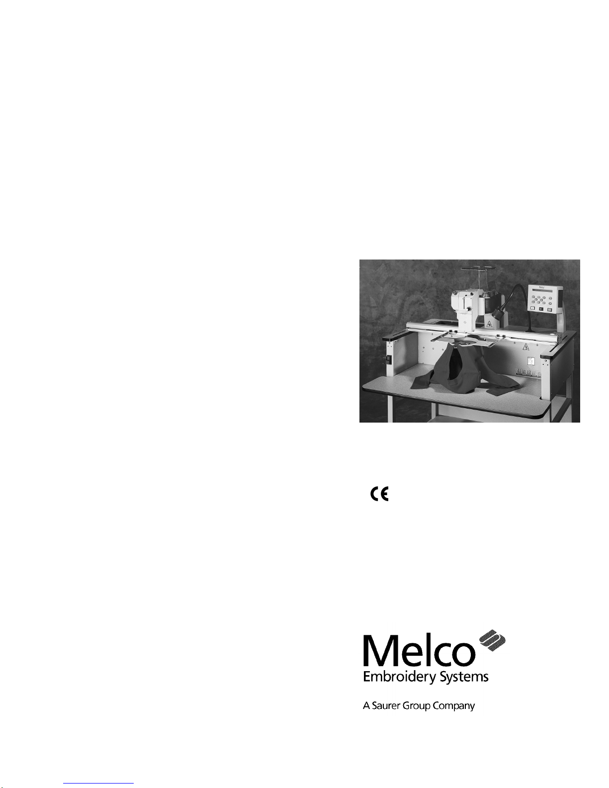
the EMT 1
embroidery peripheral
Part Number 110344-01, Revision B
• Single Head, One Needle
• Tubular Goods Hooping
•
Page 2

1575 West 124th Avenue
Denver, Colorado 80234
United States of America
Internet Address: publications@melco.com
Copyright © Melco Embroidery Systems, 1997, 1998
ALL RIGHTS RESERVED No part of this publication may be reproduced, stored in a retrieval system, or
transmitted in any form or by any means (electronic, mechanical, photocopying, recording, or
otherwise) without prior written approval of Melco Embroidery Systems. Melco reserves the right to
revise this publication and to make changes in it at any time without obligation of Melco to notify any
person or organization of such revisions or changes.
All precautions have been taken to avoid errors or misrepresentations of facts, equipment, or products.
However, Melco Embroidery Systems does not assume any liability to any party for loss or damage
caused by errors or omissions.
Printed in the United States of America
First Printing: April, 1997
Revision B: March, 1998
Page 3

Table of Contents
EMT 1 Technical Manual
110344-01, Revision B
1. Introduction
Scope Of Manual . . . . . . . . . . . . . . . . . . . . . . . . . . . . . . . . . . . . . . . . . . . . . . 1 - 1
Standard Conventions Used In Manual . . . . . . . . . . . . . . . . . . . . . . . . . . . . . . 1 - 1
Glossary Of Terms. . . . . . . . . . . . . . . . . . . . . . . . . . . . . . . . . . . . . . . . . . . . . . 1 - 2
Maintenance Philosophy . . . . . . . . . . . . . . . . . . . . . . . . . . . . . . . . . . . . . . . . . 1 - 2
Good Maintenance Practice . . . . . . . . . . . . . . . . . . . . . . . . . . . . . . . . . . . 1 - 3
Static Electricity . . . . . . . . . . . . . . . . . . . . . . . . . . . . . . . . . . . . . . . . . . . . 1 - 3
Grounding Strap Use . . . . . . . . . . . . . . . . . . . . . . . . . . . . . . . . . . . . . 1 - 3
Warranty Considerations . . . . . . . . . . . . . . . . . . . . . . . . . . . . . . . . . . . . . 1 - 3
Electrical Grounding . . . . . . . . . . . . . . . . . . . . . . . . . . . . . . . . . . . . . . . . . . . . 1 - 4
Functional Arrangement . . . . . . . . . . . . . . . . . . . . . . . . . . . . . . . . . . . . . . . . . 1 - 4
Configuring the EMT 1 . . . . . . . . . . . . . . . . . . . . . . . . . . . . . . . . . . . . . . . . . . 1 - 5
Configuration Procedure . . . . . . . . . . . . . . . . . . . . . . . . . . . . . . . . . . . . . 1 - 5
Troubleshooting LEDs and Test Points. . . . . . . . . . . . . . . . . . . . . . . . . . . . . . . 1 - 6
Various Technical Specifications . . . . . . . . . . . . . . . . . . . . . . . . . . . . . . . . . . . 1 - 8
2. Service Maintenance (except embroidery head )
General. . . . . . . . . . . . . . . . . . . . . . . . . . . . . . . . . . . . . . . . . . . . . . . . . . . . . . 2 - 1
Drive Belt Tensions . . . . . . . . . . . . . . . . . . . . . . . . . . . . . . . . . . . . . . . . . . 2 - 1
Keyboard Section . . . . . . . . . . . . . . . . . . . . . . . . . . . . . . . . . . . . . . . . . . . . . . 2 - 2
Keyboard/Display Replacement. . . . . . . . . . . . . . . . . . . . . . . . . . . . . . . . . 2 - 2
Display Screen Intensity . . . . . . . . . . . . . . . . . . . . . . . . . . . . . . . . . . . . . . 2 - 3
Disk Drive . . . . . . . . . . . . . . . . . . . . . . . . . . . . . . . . . . . . . . . . . . . . . . . . . . . . 2 - 4
Lamp Assembly . . . . . . . . . . . . . . . . . . . . . . . . . . . . . . . . . . . . . . . . . . . . . . . . 2 - 4
Bobbin Winder . . . . . . . . . . . . . . . . . . . . . . . . . . . . . . . . . . . . . . . . . . . . . . . . 2 - 5
E-Stop Switch Replacement. . . . . . . . . . . . . . . . . . . . . . . . . . . . . . . . . . . . . . . 2 - 6
Power Distribution Section . . . . . . . . . . . . . . . . . . . . . . . . . . . . . . . . . . . . . . . 2 - 8
Voltage Adjustments . . . . . . . . . . . . . . . . . . . . . . . . . . . . . . . . . . . . . . . . 2 - 8
Remove Table Top . . . . . . . . . . . . . . . . . . . . . . . . . . . . . . . . . . . . . . . . . . 2 - 8
Module Replacement . . . . . . . . . . . . . . . . . . . . . . . . . . . . . . . . . . . . . . . . 2 - 8
Electronics Section . . . . . . . . . . . . . . . . . . . . . . . . . . . . . . . . . . . . . . . . . . . . 2 - 11
Remove Table Top . . . . . . . . . . . . . . . . . . . . . . . . . . . . . . . . . . . . . . . . . 2 - 11
Remove Card Cage Cover . . . . . . . . . . . . . . . . . . . . . . . . . . . . . . . . . . . 2 - 11
Card Cage Components. . . . . . . . . . . . . . . . . . . . . . . . . . . . . . . . . . . . . 2 - 12
CPU PCB. . . . . . . . . . . . . . . . . . . . . . . . . . . . . . . . . . . . . . . . . . . . . . . . . 2 - 12
Ethernet Network PCB . . . . . . . . . . . . . . . . . . . . . . . . . . . . . . . . . . . . . . 2 - 13
Interface PCB . . . . . . . . . . . . . . . . . . . . . . . . . . . . . . . . . . . . . . . . . . . . . 2 - 14
Low Voltage Driver PCB . . . . . . . . . . . . . . . . . . . . . . . . . . . . . . . . . . . . . 2 - 14
XYZ Motor Driver Amplifiers. . . . . . . . . . . . . . . . . . . . . . . . . . . . . . . . . . 2 - 15
Backplane PCB . . . . . . . . . . . . . . . . . . . . . . . . . . . . . . . . . . . . . . . . . . . . 2 - 15
i
Page 4

Table of Contents
110344-01, Revision B
EMT 1 Technical Manual
X Beam Assembly . . . . . . . . . . . . . . . . . . . . . . . . . . . . . . . . . . . . . . . . . . . . . 2 - 17
3. Embroidery Head Maintenance
General. . . . . . . . . . . . . . . . . . . . . . . . . . . . . . . . . . . . . . . . . . . . . . . . . . . . . . 3 - 1
Arm and Bed Assembly . . . . . . . . . . . . . . . . . . . . . . . . . . . . . . . . . . . . . . . . . . 3 - 1
Thread Saddle . . . . . . . . . . . . . . . . . . . . . . . . . . . . . . . . . . . . . . . . . . . . . . . . . 3 - 1
Z Motor Replacement . . . . . . . . . . . . . . . . . . . . . . . . . . . . . . . . . . . . . . . . . . . 3 - 2
Z Shaft Encoder. . . . . . . . . . . . . . . . . . . . . . . . . . . . . . . . . . . . . . . . . . . . . . . . 3 - 4
Needle Case . . . . . . . . . . . . . . . . . . . . . . . . . . . . . . . . . . . . . . . . . . . . . . . . . . 3 - 9
Rotary Hook . . . . . . . . . . . . . . . . . . . . . . . . . . . . . . . . . . . . . . . . . . . . . . . . . 3 - 22
X Motor . . . . . . . . . . . . . . . . . . . . . . . . . . . . . . . . . . . . . . . . . . . . . . . . . 2 - 17
Motor Replacement . . . . . . . . . . . . . . . . . . . . . . . . . . . . . . . . . . . . . 2 - 17
X Drive Belt. . . . . . . . . . . . . . . . . . . . . . . . . . . . . . . . . . . . . . . . . . . . . . . 2 - 19
Replacement . . . . . . . . . . . . . . . . . . . . . . . . . . . . . . . . . . . . . . . . . . 2 - 19
Belt Tension . . . . . . . . . . . . . . . . . . . . . . . . . . . . . . . . . . . . . . . . . . . 2 - 20
Lint Wiper. . . . . . . . . . . . . . . . . . . . . . . . . . . . . . . . . . . . . . . . . . . . . . . . 2 - 21
Y Motor . . . . . . . . . . . . . . . . . . . . . . . . . . . . . . . . . . . . . . . . . . . . . . . . . 2 - 21
Replacement . . . . . . . . . . . . . . . . . . . . . . . . . . . . . . . . . . . . . . . . . . 2 - 21
Y Motor Belt. . . . . . . . . . . . . . . . . . . . . . . . . . . . . . . . . . . . . . . . . . . . . . 2 - 23
Belt Tension Adjustment. . . . . . . . . . . . . . . . . . . . . . . . . . . . . . . . . . 2 - 23
Y Drive Belt. . . . . . . . . . . . . . . . . . . . . . . . . . . . . . . . . . . . . . . . . . . . . . . 2 - 25
Replacement . . . . . . . . . . . . . . . . . . . . . . . . . . . . . . . . . . . . . . . . . . 2 - 25
Belt Tension Adjustment. . . . . . . . . . . . . . . . . . . . . . . . . . . . . . . . . . 2 - 28
Removal . . . . . . . . . . . . . . . . . . . . . . . . . . . . . . . . . . . . . . . . . . . . . . . . . . 3 - 1
Belt Tension . . . . . . . . . . . . . . . . . . . . . . . . . . . . . . . . . . . . . . . . . . . . . . . 3 - 3
Introduction . . . . . . . . . . . . . . . . . . . . . . . . . . . . . . . . . . . . . . . . . . . . . . . 3 - 4
Inspection. . . . . . . . . . . . . . . . . . . . . . . . . . . . . . . . . . . . . . . . . . . . . . . . . 3 - 5
Installation . . . . . . . . . . . . . . . . . . . . . . . . . . . . . . . . . . . . . . . . . . . . . . . . 3 - 6
Calibration . . . . . . . . . . . . . . . . . . . . . . . . . . . . . . . . . . . . . . . . . . . . . . . . 3 - 7
Thread Tensioner Assembly Replacement . . . . . . . . . . . . . . . . . . . . . . . . . 3 - 9
Thread Check Spring Replacement . . . . . . . . . . . . . . . . . . . . . . . . . . . . . 3 - 10
Thread Check Spring Adjustment. . . . . . . . . . . . . . . . . . . . . . . . . . . . . . 3 - 11
Adjustment Hints . . . . . . . . . . . . . . . . . . . . . . . . . . . . . . . . . . . . . . . 3 - 11
Replacing The Needle Bar / Presser Foot / Associated Parts . . . . . . . . . . . 3 - 12
Needle Case Removal . . . . . . . . . . . . . . . . . . . . . . . . . . . . . . . . . . . . . . 3 - 14
Jump Stitch Solenoid Replacement . . . . . . . . . . . . . . . . . . . . . . . . . . . . . 3 - 16
Jump Stitch Solenoid Adjustment. . . . . . . . . . . . . . . . . . . . . . . . . . . . . . 3 - 17
Plunger Positioning. . . . . . . . . . . . . . . . . . . . . . . . . . . . . . . . . . . . . . 3 - 17
Bracket Positioning. . . . . . . . . . . . . . . . . . . . . . . . . . . . . . . . . . . . . . 3 - 18
Replacing Reciprocator / Needle Bar Guide Shaft . . . . . . . . . . . . . . . . . . 3 - 20
Hook Replacement . . . . . . . . . . . . . . . . . . . . . . . . . . . . . . . . . . . . . . . . . 3 - 22
Needle Depth . . . . . . . . . . . . . . . . . . . . . . . . . . . . . . . . . . . . . . . . . . 3 - 24
Hook Timing Adjustments Only . . . . . . . . . . . . . . . . . . . . . . . . . . . . . . . 3 - 27
ii
Page 5

Table of Contents
EMT 1 Technical Manual
110344-01, Revision B
4. Accessory Adjustments
Wide Angle Cap Frame . . . . . . . . . . . . . . . . . . . . . . . . . . . . . . . . . . . . . . . . . . 4 - 1
Cap Supports . . . . . . . . . . . . . . . . . . . . . . . . . . . . . . . . . . . . . . . . . . . . . . 4 - 1
Cap Support Pads. . . . . . . . . . . . . . . . . . . . . . . . . . . . . . . . . . . . . . . . . . . 4 - 2
Driver Bar Cable . . . . . . . . . . . . . . . . . . . . . . . . . . . . . . . . . . . . . . . . . . . . 4 - 2
Spindles On The Clamps. . . . . . . . . . . . . . . . . . . . . . . . . . . . . . . . . . . . . . 4 - 3
Clip Posts . . . . . . . . . . . . . . . . . . . . . . . . . . . . . . . . . . . . . . . . . . . . . . . . . 4 - 3
Cap Frame . . . . . . . . . . . . . . . . . . . . . . . . . . . . . . . . . . . . . . . . . . . . . . . . 4 - 4
iii
Page 6

Table of Contents
110344-01, Revision B
EMT 1 Technical Manual
This page intentionally left blank
iv
Page 7

1. Introduction
110344-01, Rev B 1. Introduction
Scope Of Manual
The EMT 1 Embroidery Peripheral Technical Manual is a guide for performing repairs
and adjustments which go beyond routine operator maintenance.
Although these procedures are best understood and performed by professional
service technicians in conjunction with specific factory technical training, much of
the information in this manual may be useful reference for others who might
possess appropriate technical aptitude and skills.
If any information in this manual is not fully understood, however, you are advised
to contact your local Melco equipment service organization for assistance. You will
find they are professional service technicians trained on Melco equipment, who
have acquired technical expertise through experience and other general technical
training. Additionally, Melco equipment technicians routinely receive up to date
servicing information which continually enhances their product knowledge.
1 - 1
This technical manual is presented in four Sections: 1) an overview of general
information useful in understanding the manual and various service requirements,
2) service maintenance of all the machine areas except the embroidery head,
3) embroidery head maintenance, and 4) accessory adjustments. Sections 2, 3, and
4 address mechanical disassembly and replacement of the major components of the
embroidery peripheral and any related machine adjustments.
Standard Conventions Used In Manual
Throughout this manual abbreviations and specific terms may be used. The
following explains some of this terminology:
When speaking of a "printed circuit board," the item may quite often be referred
to as a "PCB."
The terms "X Beam", "Y Beam", "Beam", "Carriage", "Carriage Assembly" and
"Pantograph" may all refer to the same general area.
Certain procedures in the manual require actions such as pressing a certain key, or
typing some letters at the computer keyboard. The following is a list of some of the
more commonly used conventions found in this manual.
• To indicate a key on the computer keyboard, the key in question is simply
referred to, for example: Press the Enter key to initiate the application.
• A key on the peripheral keyboard is represented by a pictorial of that key.
• Typing with the computer keyboard is referred to in BOLD letters, for
example: Type: run and press Enter to start.
Page 8

1 - 2 Maintenance Philosophy
EMT 1 Technical Manual Melco Embroidery Systems
• To indicate that two or more keys must be pressed to obtain a desired
result, each key is indicated with commas between them. An example is:
Press Shift,8 to type an asterisk (*).
Occasionally in the manual, special attention by the user is required. In this
situation, "attention getters" are used to indicate the need for the user to be aware
of a situation that is above and beyond the normal or routine. Three standard
attention getters are explained below:
WARNING!
This term is used to call attention to the user that the procedure
following must be performed with care and accuracy to avoid possible
damage to property or personal injury to the operator or other persons in
the area. This term is also used to announce important regulatory
information.
CAUTION!
This term is used when the procedure following it may cause damage
to the equipment or other property if not properly performed by the user.
NOTE:
This term is used when additional information is required beyond
the normal steps for communicating the information. It may be used to
clarify certain portions of text or to call attention to other items previously
mentioned or mentioned later in the procedure.
Glossary Of Terms
Several words or terms are used in this manual that are unique or specialized in use
with the embroidery industry or Melco embroidery equipment. A glossary of these
terms is located in the operation manual.
Maintenance Philosophy
The maintenance philosophy used in this manual, and practiced at Melco, is to
isolate potential problems within the system to a "practical" replacement assembly.
Therefore, components are typically not repaired, but rather, a circuit board or
mechanical "assembly" may be replaced. In the process of isolating problems in the
machine, the person performing the trouble shooting must also practice good
trouble shooting techniques. Good trouble shooting techniques include, but are not
limited to, guarding against static electricity causing further damage to machine
components; and only replacing one part at a time to enable identification of the
defective part after the machine is repaired.
Page 9

Warranty Considerations 1 - 3
110344-01, Rev B 1. Introduction
Good Maintenance Practice
The procedures in this manual are guidelines for performing repair maintenance
and must be used by personnel practicing good maintenance and repair technique.
Good maintenance technique includes, but is not limited to, adhering to all
precautions and safety considerations when working on the unit, and using the
correct tools for the job being performed.
WARNING! Personal injury may result if proper precautions are
not observed. Remove rings, watches, and any other metallic
objects from hands and wrists before servicing the machine.
Remove metallic articles from shirt pockets to prevent them
from falling into the machine. Do not place hands under the
needle or needle bar. Do not allow loose clothing to come in
contact with moving parts of the machine. Under certain
conditions of machine failure the moving parts of the machine
may not be controllable by normal means. At these times the
machine may operate without notice.
Static Electricity
As with all computerized equipment, the EMT 1 Embroidery Peripheral is sensitive to
static electricity. Any time work is performed inside covered areas of the embroidery
peripheral, the person performing the work
MUST be using a static grounding strap.
WARNING! Failure to use a grounding strap, or failure to
practice other good maintenance/repair techniques may cause
damage to the machine and possible harm to personnel.
Grounding Strap Use
The grounding strap must be connected in the proper manner to insure the static
charge on the persons body is neutralized to the chassis ground level of the
embroidery peripheral when working in the electronic areas under the covers.
DO NOT attempt to use any grounding strap that is not specifically designed for
static use. A "straight-wire" grounding device (one without built-in resistance) will
place the operator in danger of exposure to dangerous voltages. It is recommended
that the static strap be checked during daily use for proper resistance protection.
Warranty Considerations
Many areas of maintenance in this manual require factory trained personnel to
assure proper service. Any service that is improperly performed may cause the
warranty to be voided.
Page 10
1 - 4 Functional Arrangement
EMT 1 Technical Manual Melco Embroidery Systems
Electrical Grounding
WARNING! It is very important that the power cord be plugged
into a properly wired electrical outlet. Failure to have a
properly wired outlet may result in damage to the equipment
and injury to personnel. It is recommended that a licensed
electrician be consulted to assure that the electrical outlet is
properly wired and grounded.
CAUTION! If a properly wired electrical outlet is not used for the source supply
voltage to the System, electrical failures may result.
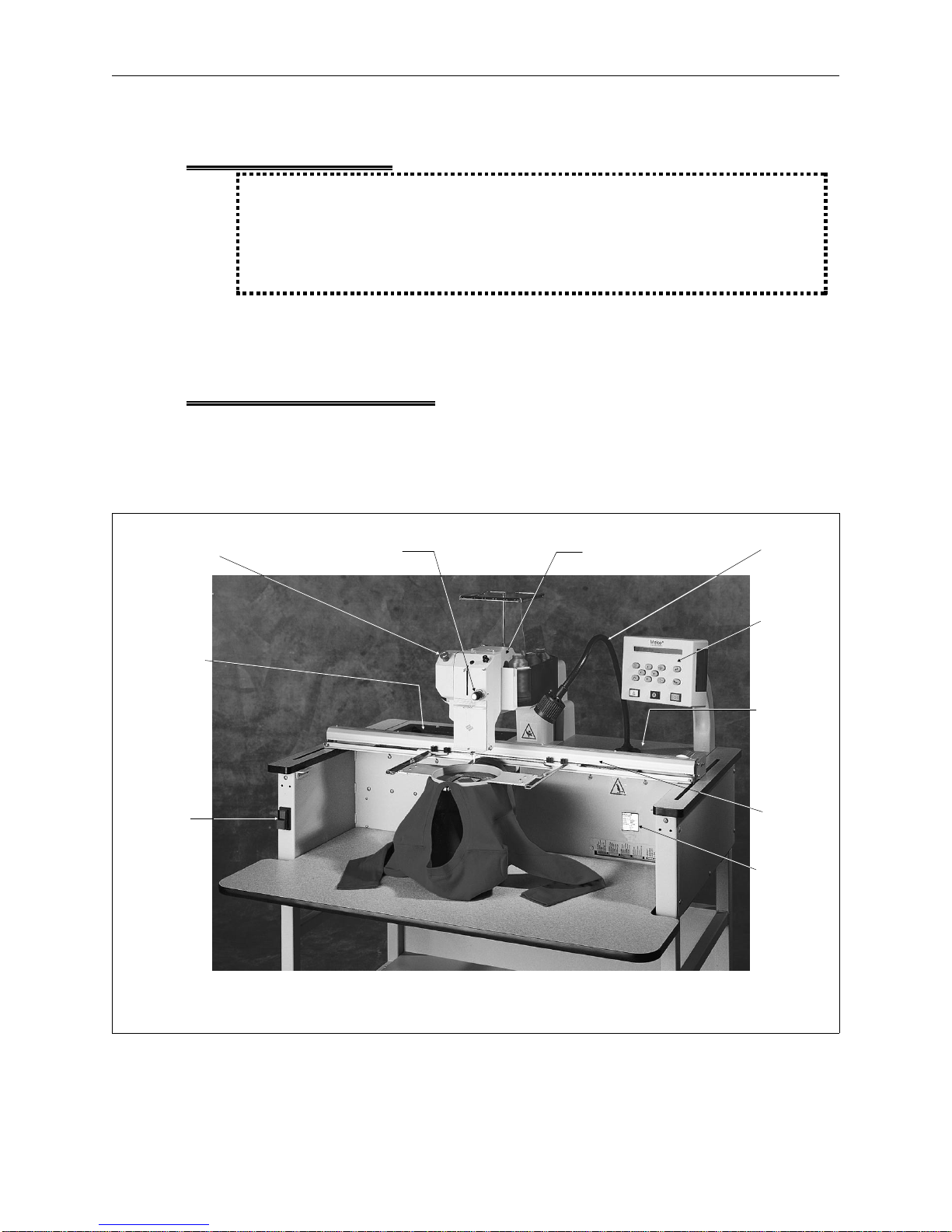
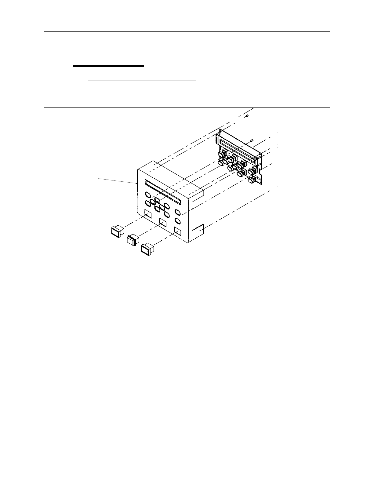
Functional Arrangement
The EMT 1 is functionally arranged into several sections including the electronics, a
power supply section, the keyboard and disk drive, the Embroidery Head, and the
Carriage section. Figure 1-1 shows the general locations of these and other
functional parts of the embroidery peripheral.
e-stop switch
power supply
section
(under rear
table top or
optional
bobbin winder
assembly)
ON/OFF
switch
assembly
tensioner
and needle
case
thread
saddle
flexible
lamp
Keyboard
and Disk
Drive
electronics
section
(under rear
table top)
carriage
serial # tag
Figure 1 - 1
Page 11

Configuration Procedure 1 - 5
110344-01, Rev B 1. Introduction
Configuring the EMT 1
During the operation of the EMT 1, certain situations may arise when the peripheral
does not respond to keyboard commands. You may often recover from this type of
situation by performing what is called "Configuring" (or Re-configuring) the
embroidery peripheral.
You must also configure the peripheral any time you install a new CPU (
Central
Processor Unit) printed circuit board.
Configuration is initially set at the factory. However, if for any reason the
configuration is not set properly, or if you have replaced the CPU board, you should
know how to set the configuration.
NOTICE: Re-configuring your EMT 1 will
clear the power fail rescue function for the
current situation.
There are two items that must be set in each EMT 1 Embroidery Peripheral before it
is used in the Melco system for the first time.
First you must set the
Peripheral Program. The CPU PCB used on the EMT 1
Embroidery Peripheral may also be used in other embroidery peripherals produced
at Melco. Therefore, you must tell the CPU board what peripheral it is being used in.
If the CPU PCB is ever replaced, you must reconfigure the peripheral before using it
again.
CAUTION! If the EMT 1 is not configured with the correct Peripheral Program, it will
not run properly, and may become damaged.
The second configuration item is the
Network Address. The address must be
different for each peripheral attached to an EDS II or EDS III computer or network.
There may be up to 64 (16 if using EDS II software) total embroidery peripherals
attached to any one computer, and each must have its own unique identification.
The EMT 1 uses an Ethernet network card which allows the address to contain the
numbers 0 through 9, all 26 English letters, three symbols (-, /, and *), or any
combination of these characters. The maximum number of characters that can be
used in the network address is sixteen.
Configuration Procedure
Refer to the operation manual for the procedure to configure or re-configure the
EMT 1 Embroidery Peripheral.
Page 12
1 - 6 Troubleshooting LEDs and Test Points
EMT 1 Technical Manual Melco Embroidery Systems
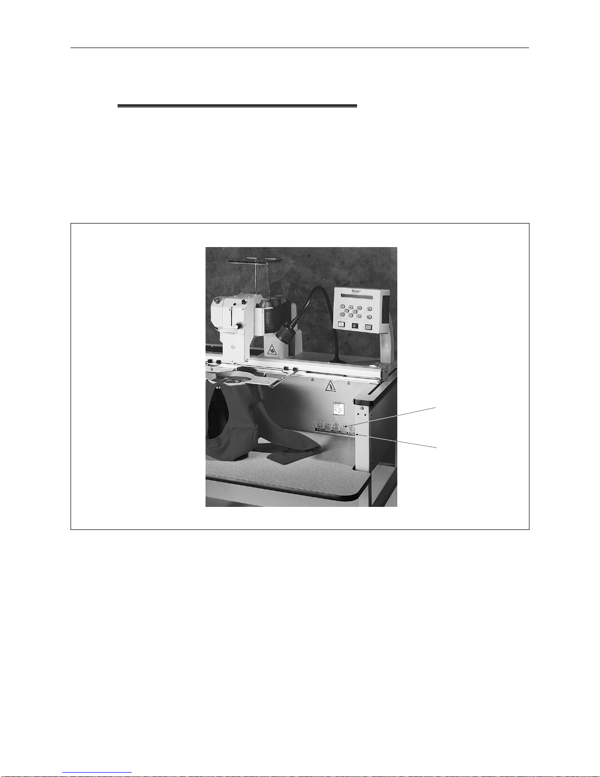
Troubleshooting LEDs and Test Points
At the front of the EMT 1 is a metal cover plate over a variety of indicator LED lights
and a series of test points for checking certain voltages with a multimeter. This area
is provided for observing various machine conditions, especially while
troubleshooting problems that may occasionally occur. To access this area, remove
the screws holding the cover, flip the cover over so the lettering on the cover is
visible (as shown in Figure 1-2), and reinstall the cover in the same holes but above
the LED opening. The lettering on flip-side of the cover is a brief title for each of the
LED and test point locations. You may also refer to Figure 1-3 for this information.
Figure 1 - 2
lettering on
metal cover
indicator LED
lights and
test points
Page 13
Configuration Procedure 1 - 7
110344-01, Rev B 1. Introduction
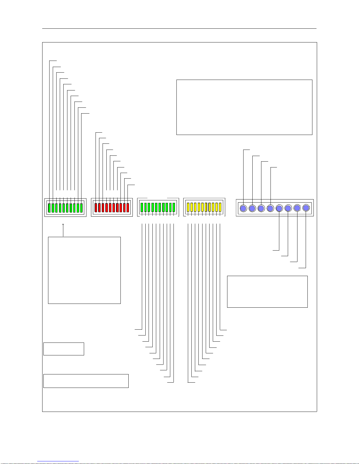
GREEN (all should be ON)
1) I/O FPGA (I/O IC on CPU configured OK at startup)
2) Control FPGA (Control IC on CPU configured OK at startup)
3) +5V (Power OK from CPU)
4) +6V (Isolated) OK
5) +36V OK (see note **)
6) +24V OK
7) -12V OK
8) +12V OK
9) +5V (+12V based) OK
10) +5V (+24V based) OK
RED
(all should be OFF)
1) Estop Engaged
2) Light Fuse Blown
3) Bobbin Fuse Blown
4) Disregard,
5) Disregard, Not Used with EMT 1
6) Z Motor Current Limit Error
7) Y Motor Current Limit Error
8) X Motor Current Limit Error
9) Y Home not functioning
10) X Home not functioning
GREEN
RED
Not Used with EMT 1
GREEN YELLOW
* TEST POINT Voltage Tolerances
+6 VDC ISO (+5.6 to +6.1 VDC)
+36 VDC [without load] (+30 to +37 VDC)
+36 VDC [with 20-100% load] (+34.2 to +37.8 VDC)
+24 VDC (+22.8 to +25.2 VDC)
-12 VDC (-10.8 to -13.2 VDC)
+12 VDC (+11.4 to +12.6 VDC)
+5 VDC (+4.9 to +5.1 VDC)
ISO RET (Isolated GND)
+6 VDC ISO *
+36 VDC *
+24 VDC *
TEST POINTS *
1 2 3 4 5 6 7 8 9 10 1 2 3 4 5 6 7 8 9 10 TEST POINTS *
1 2 3 4 5 6 7 8 9 10 1 2 3 4 5 6 7 8 9 10
Note ** +36 VDC
When the peripheral is first
turned on and before the
program is downloaded,
-12 VDC *
+12 VDC *
the +36.0 VDC LED may be
blinking. This is normal. But
after the machine initializes,
and the motors become
energized, if the blinking
does not stop the power
supply may be marginal.
GREEN
(2) through (5) ON, others as indicated)
(ON only at Head Up) Z Index (1
Watch Dog (2
(see note ***) Z Hall (3
(7) ON until motors
initiated, then OFF
Disregard,
(see note ***) Y Hall (4
(see note ***) X Hall (5
Not Used with EMT 1 (6
XYZ Motor Brakes (7
Disregard,
(9) & (10) ON - one side of axis center,
OFF - other side of axis center
Not Used with EMT 1 (8
Y Home (9
X Home (10
YELLOW
10) Disregard, Not Used with EMT 1
9) Disregard, Not Used with EMT 1
8) Disregard, Not Used with EMT 1
7) Disregard, Not Used with EMT 1
6) Disregard, Not Used with EMT 1
5) Disregard, Not Used with EMT 1
4) Disregard, Not Used with EMT 1
3) Disregard, Not Used with EMT 1
2) Standard Cap Frame (ON when Installed)
1) Wide Angle Cap Frame (ON when Installed)
Note *** Hall - Sensors in the
motor which indicate defective
(dead spot) sections in the
motor. Only OFF at dead spot
positions in the motor rotation.
(conditions as indicated)
+5 VDC *
GND
EMT 1
Figure 1 - 3
Page 14

1 - 8 Various Technical Specifications
EMT 1 Technical Manual Melco Embroidery Systems
Various Technical Specifications
The following is a list of various tension and force specifications for the EMT 1 (All
specifications to be within plus or minus 10% unless otherwise indicated):
X Drive Belt Tension. . . . . . . . . . . . . . . . . . . . . . . . . . . . . . . . . . . . . . 25 pounds
Y Drive Belt Tensions . . . . . . . . . . . . . . . . . . . . . . . . . . . . . . . . . . . . . 40 pounds
Y Motor Belt Tension . . . . . . . . . . . . . . . . . . . . . . . . . . . . . . . . . . . . . 40 pounds
Z Motor Belt Tension . . . . . . . . . . . . . . . . . . . . . . . . . . . . . . . . . 7 (+/- 1) pounds
X Carriage Friction . . . . . . . . . . . . . . . . . . . . . . . . . . . . . . . . . . . . 5 +/- 2 pounds
Y Beam Friction . . . . . . . . . . . . . . . . . . . . . . . . . . . . . . . . . . . . . 12 +/- 4 pounds
NOTE: A special force gauge has been designed for adjusting the belt tensions using
unique methods that are representative of these tension specifications.
X Home Sensor Position . . . . . centered within +/- 0.015 inches
Y Home Sensor Position . . . . . 7.09 +/- 0.015 inches from arm mounting holes
in the carriage relative to the needle plate hole
Page 15

Drive Belt Tensions 2 - 1
110344-01, Rev B 2. Service Maintenance (except embroidery head )
2. Service Maintenance (except embroidery head )
General
This section of the manual provides parts replacement procedures and various
adjustments required during parts replacement or other service repairs of all areas
of the machine except the embroidery head. Embroidery head service maintenance
information is located in Section 3 of this manual. Accessory adjustment information
is located in Section 4.
These procedures are guidelines for performing repairs and must be used by
personnel practicing good maintenance and repair techniques. Refer to the
Maintenance Philosophy topics in Section 1 of this manual for discussion of good
maintenance and repair techniques, including concerns with static electricity.
WARNING! Failure to practice good maintenance and repair
technique may result in injury to personnel performing the
work, and damage to the equipment!
NOTE: The Warranty is exclusive of, and may be VOID if, poor maintenance practices
have caused damage to the equipment.
Drive Belt Tensions
CAUTION! Damage to the machine may result if belt tensions are
improperly adjusted.
All drive belts require special procedures and tools for setting the proper tensions. If
the tension settings are attempted without using the proper procedures and tools
(and without proper training in some cases), machine components may be
damaged and potential warranty issues voided.
Page 16
2 - 2 Keyboard Section
EMT 1 Technical Manual Melco Embroidery Systems
Keyboard Section
Keyboard/Display Replacement
To remove the keyboard/display assembly from the cover, refer to Figure 2-1 and
the following procedure:
Keyboard
Section
Figure 2 - 1
1. Turn OFF the power switch to the EMT 1 and remove the power cord from the
power source electrical outlet and the rear of the machine.
2. Remove the cable cover from the base plate at the rear of the keyboard/display
assembly.
3. Remove the cable strain relief plate from behind the keyboard/display assembly.
4. Remove the 4 screws from the base plate of the assembly to loosen the
keyboard/display assembly and cover.
5. Carefully slide the assembly forward until you can access the cables.
6. Pinch the locking lever of the small 2-wire connector and remove it from the
keyboard PCB.
7. Use a 3/16" nut driver and remove the 2 nuts securing the 15-pin connector to
the keyboard PCB.
Page 17
Display Screen Intensity 2 - 3
110344-01, Rev B 2. Service Maintenance (except embroidery head )
8. Remove the PCB and cover together.
9. Install a static grounding strap between the working surface and the personnel
performing this procedure.
10. Remove the 4 screws that secure the keyboard/display assembly PCB to the
cover.
11. Disconnect the 3-button harness from the PCB.
12. Remove the keyboard/display assembly PCB from the keyboard cover.
13. Transfer the key caps from the old PCB to the new PCB by simply lifting them off
of the keys by using finger pressure only. It is recommended that this be done
one key at a time to avoid errors in key cap arrangement on the new PCB.
14. When the key caps are transferred, reinstall the keyboard/display assembly by
reversing the preceding steps.
NOTE: When re-attaching the PCB to the cover, be certain the ground wire is
attached at the 4th screw and that when the screws are tightened the
buttons do not stick in the cover holes when pressed.
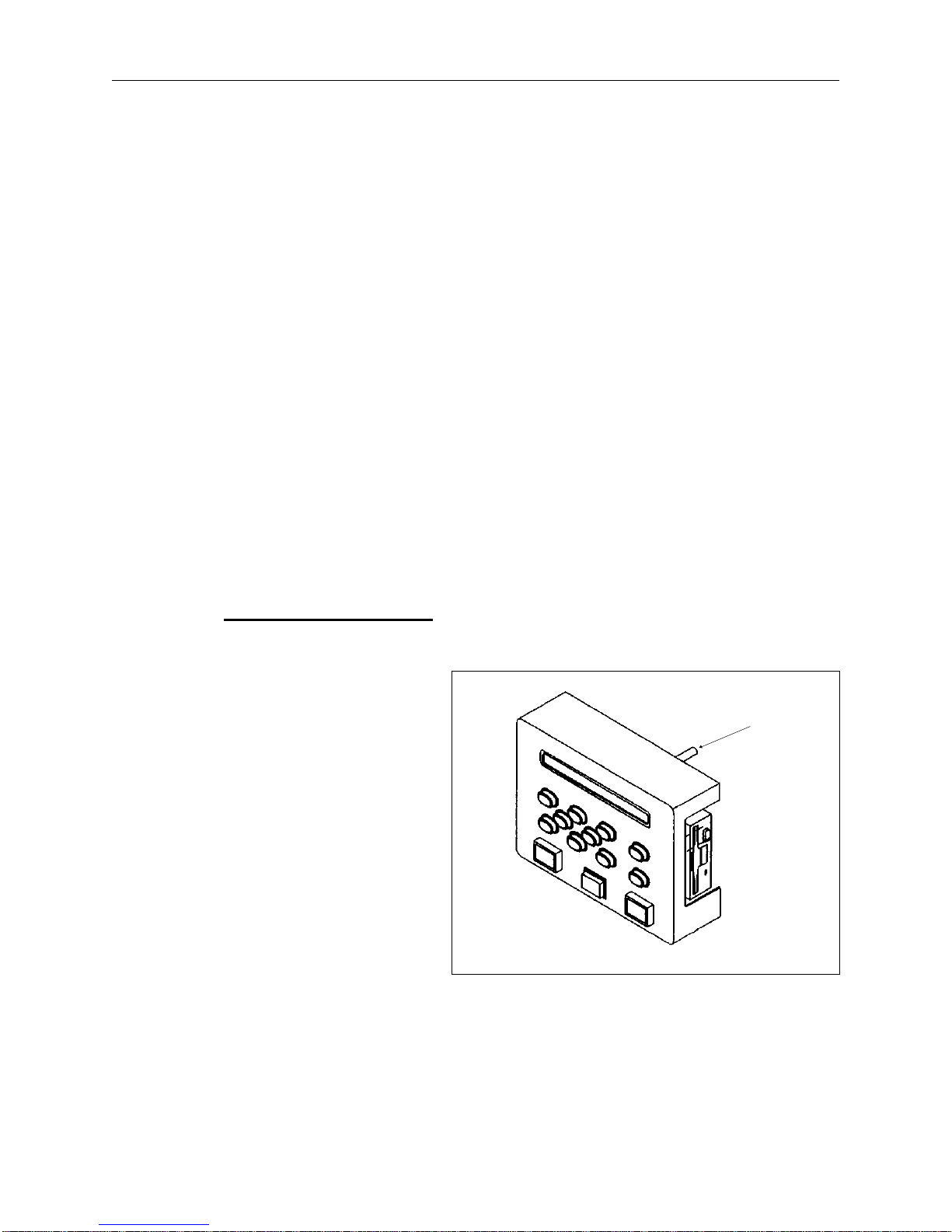
Display Screen Intensity
During the adjustment of the display intensity the EMT 1 must be turned on so the
result of the adjustment may
be observed.
intensity
1. Locate the intensity
adjustment knob on the
top, rear of the
keyboard/display printed
circuit board as shown in
Figure 2-2.
2. Turn ON the power switch
to the EMT 1.
3. When facing the machine
from the front, rotate the
adjustment potentiometer
clockwise to decrease
intensity on the display, or
counterclockwise to increase the intensity on the display.
Figure 2 - 2
adjustment
knob
Page 18
2 - 4 Lamp Assembly
EMT 1 Technical Manual Melco Embroidery Systems
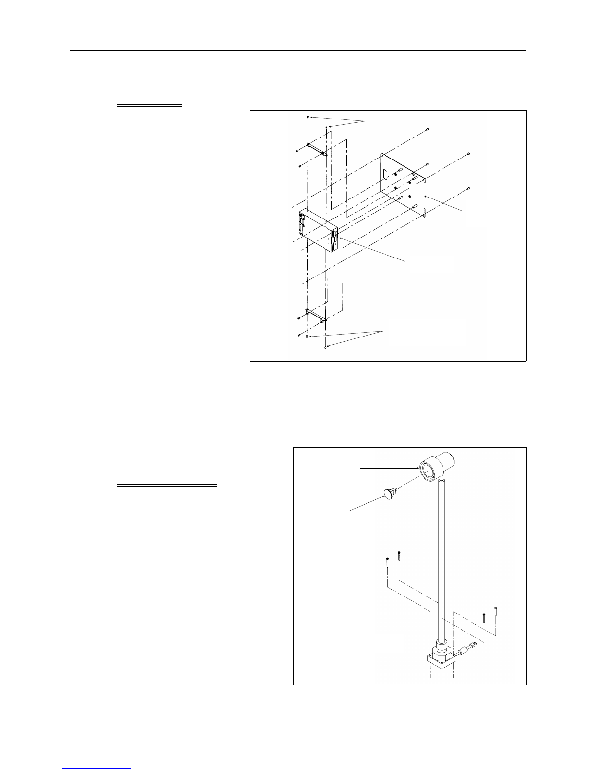
Disk Drive
1. Remove the
keyboard/display
assembly and cover
as previously
described.
2. Disconnect the disk
drive harnesses.
3. Remove the 4
screws shown in
Figure 2-3 that
hold the drive to
the side brackets.
4. Replace the disk
drive and re-install
the hardware,
harnesses, and
keyboard/display
assembly and cover
that were removed
earlier.
side bracket screws
keyboard
base plate
disk drive
side bracket
screws
Figure 2 - 3
NOTE: When installing the disk drive data ribbon orient the harness so the edge with
the colored stripe (indication pin #1) is lying adjacent to the power
harness.
bulb
Lamp Assembly
case
The halogen bulb replacement
is described in the operation
bulb
manual. The bulb has 2 pins that
simply plug into the base socket
at the end of the lamp post. The
bulb case must be removed by
rotating it counter-clockwise off
the base to access the lamp.
Lamp Assembly
Figure 2 - 4
Page 19
Display Screen Intensity 2 - 5
110344-01, Rev B 2. Service Maintenance (except embroidery head )
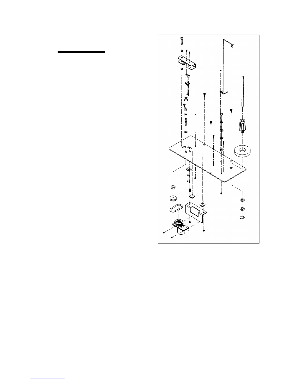
Bobbin Winder
The optional bobbin winder is
mounted in the left rear table top.
There is no need to remove the
bobbin winder assembly from the
table top to service it. Simply remove
the 4 truss screws holding the table
top over the power distribution
section. As you lift the table top and
bobbin winder assembly upward,
disconnect the two harnesses going to
the bobbin winder motor and switch.
The built in bobbin winder receives its
power from the EMT 1 12 V source.
Winding starts by moving the actuator
lever to the start position. The winding
operation stops when the thread in
the bobbin triggers the switch inside
the actuator lever. The operation may
manually be stopped by moving the
actuator lever away from the start
position by hand.
The bobbin winder motor is equipped
with a thermal switch to protect the
motor and circuitry in the event of an
overload condition. If the bobbin
winder stops due to an overload or
overheating:
Bobbin Winder
Assembly Parts
(see EMT 1 illustrated
parts manual for
descriptions)
Figure 2 - 5
1. Move the actuator lever to the OFF
position.
2. Clear the obstruction and/or lubricate the drive shaft.
3. When the motor cools, the thermal switch will reset.
4. Move the actuator lever to the ON position and resume operation.
Refer to Figure 2-5 for an illustration of the various parts and their orientation in
making up the bobbin winder assembly.
For proper operation of the bobbin winder option, refer to the bobbin winder
section in the EMT 1 peripheral operation manual.
Page 20
2 - 6 E-Stop Switch Replacement
EMT 1 Technical Manual Melco Embroidery Systems
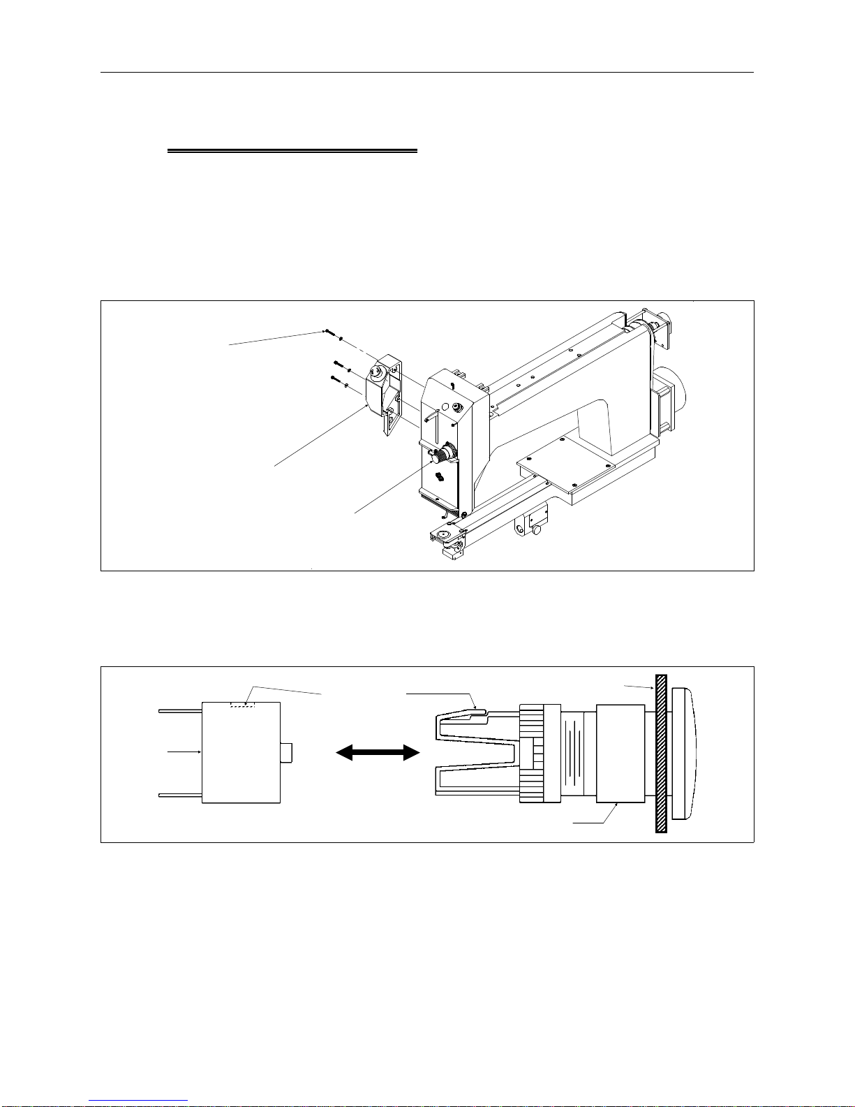
E-Stop Switch Replacement
The emergency stop switch is located just to the left of the needle case assembly.
Refer to the following procedure to replace this switch:
1. Turn OFF the peripheral and unplug the power cord from the source.
2. Remove the three screws on the side of the e-stop cover, then remove the cover
from the left side of the needle case assembly as shown in Figure 2-6.
left side
tensioner
cover
switch
block
e-stop
switch
assembly
thread
tensioner
assembly
Figure 2 - 6
3. Loosen the locking collar on the e-stop switch assembly at the inside surface of
the cover (see Figure 2-7).
depress here
through the
switch block
locking collar
Figure 2 - 7
e-stop cover
(inside surface)
4. Refer to Figure 2-7 to locate the small square opening in the switch block
through which you will see the small locking tab on the switch assembly body.
5. Remove the switch block by depressing the tab on the assembly body through
the opening in the switch block and sliding the switch block off the end of the
assembly body.
Page 21
Display Screen Intensity 2 - 7
110344-01, Rev B 2. Service Maintenance (except embroidery head )
6. Remove the locking collar the rest of the way off the assembly and remove the
remainder of the e-stop switch assembly.
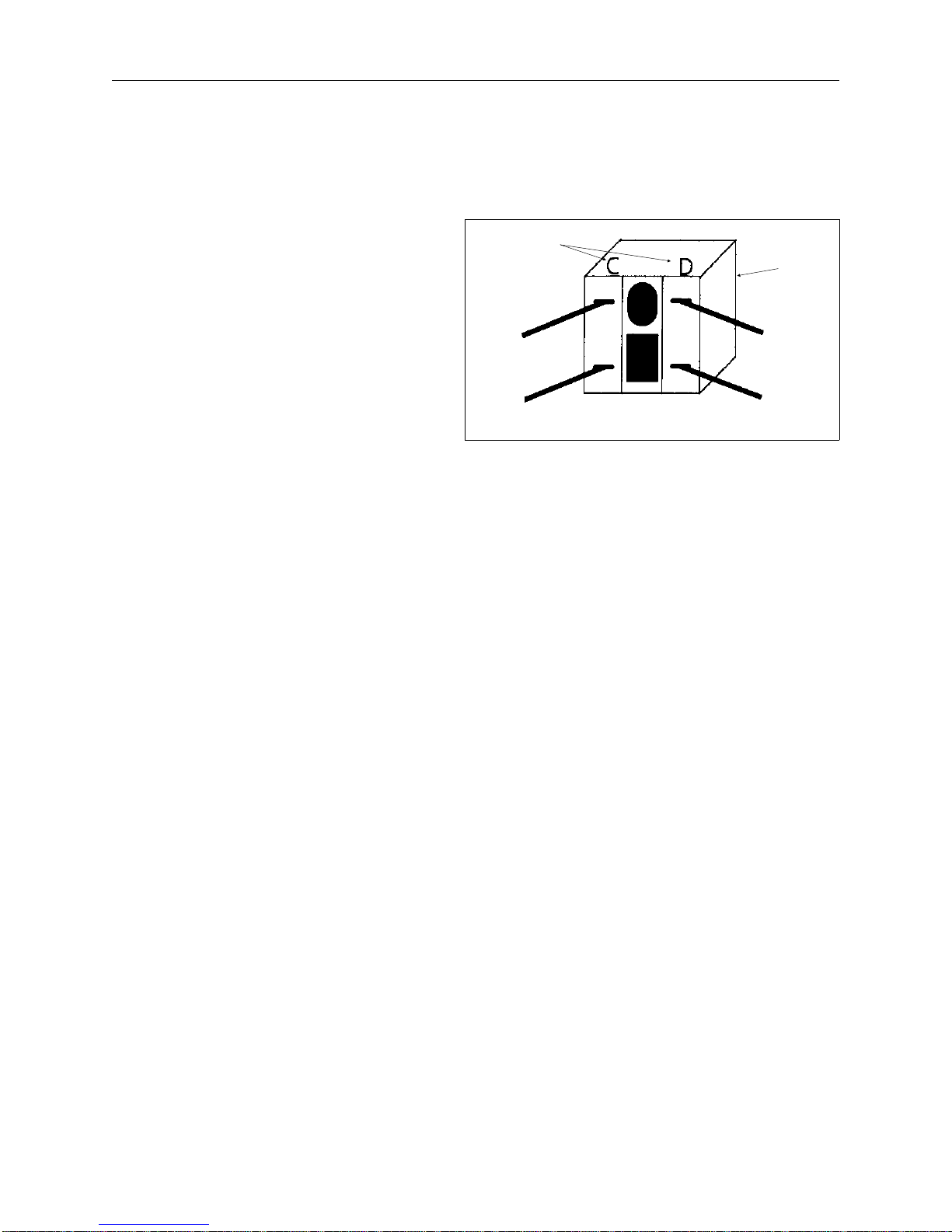
7. Install a new e-stop switch
assembly by reversing the
previous steps for removing
the old one. The switch
switch pole
markings
switch
block
block and assembly body
are keyed for assembly in
one orientation only.
wire C
wire D
8. When the new switch block
is pressed onto the end of
the switch assembly,
wire (C)
wire (D)
transfer the wires one at a
time to keep them in the
Figure 2 - 8
proper order (refer to the
diagram in Figure 2-8).
As shown in the figure, the two wires labeled with C and (C) are connected to
the pole marked C. The two wires labeled with D and (D) are connected to the
pole marked D.
Page 22

2 - 8 Power Distribution Section
EMT 1 Technical Manual Melco Embroidery Systems
Power Distribution Section
This section is comprised of various functions including power entry, line filter, and
switching circuitry for 110 or 220 volt operation. The various voltage sources for
logic circuits, motors, and solenoids are integrated into the power distribution
module. Additionally, the e-stop controls are built into the PCB located in this
module (see Figure 2-9). The section is located under the left rear table top.
Voltage Adjustments
The voltage values are set at the factory and are regulated within the operating
ranges of the peripheral.
Should any voltage drift out of its operating range, the module must be replaced.
Remove Table Top
To access the power distribution section for replacing the power module, remove
the left rear table top (with optional bobbin winder assembly) described as follows:
NO further adjustments are required for voltage values.
1. Loosen the left rear table top (with optional bobbin winder assembly) by
loosening the 4 truss screws (2 at the front and 2 at the rear).
Caution: If the optional bobbin winder is installed, you must
disconnect the two harnesses going to the bobbin winder assembly
as you lift the table top upward.
2. Lift the table top up and disconnect the bobbin winder harnesses if the bobbin
winder assembly is installed. Remove the table top to a safe storage area.
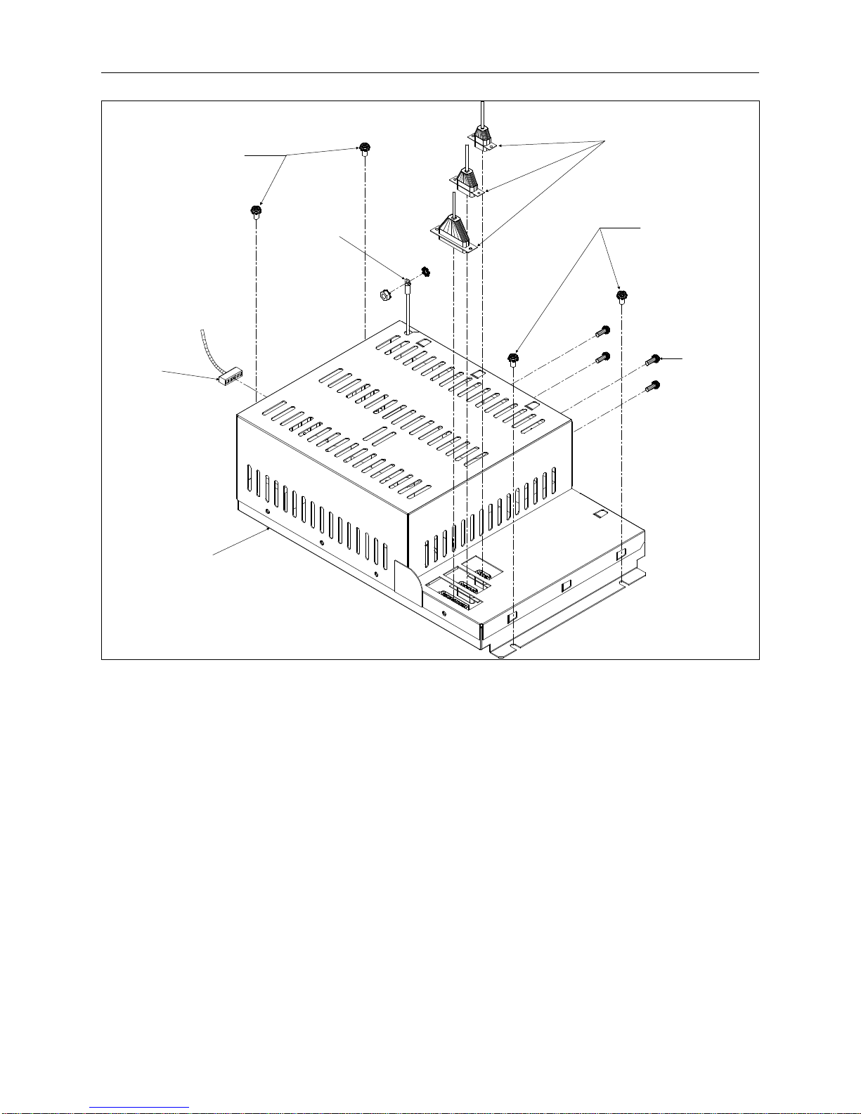
Module Replacement
The power distribution module is replaced as an entire assembly regardless of which
of the areas included within the module is malfunctioning. To replace the module
refer to the following steps:
1. Turn OFF the peripheral and unplug the power cord from the source.
2. Refer to the procedure for removing the left rear table top (with optional bobbin
winder assembly) and remove the table top.
3. Remove the five truss head screws and the left side cover of the peripheral to
enable access to the power switch harness connector shown in Figure 2-9.
4. Refer to Figure 2-9 and remove all of the harness connections entering the power
distribution module. In addition to the three harnesses entering the top and the
power switch harness at the side, there is a ground wire attached to a stud near
the rear left corner of the power distribution section that must be removed.
Page 23
Module Replacement 2 - 9
110344-01, Rev B 2. Service Maintenance (except embroidery head )
the two left
side screws at
the base of the
distribution
section (loosen
screws ONLY)
ground
wire
power
switch
harness
three harnesses
entering at the top
the two right
side screws at
the base of the
distribution
section (remove
completely)
four
screws at
the rear
of the
peripheral
power
distribution
module
5. At the rear of the peripheral, remove the four screws holding the power
6. At the side of the module next to the left peripheral wall, loosen the two M5 pan
7. Remove the remaining two M5 pan head screws holding the power distribution
8. The slots under the two loosened screws near the peripheral wall are shaped in a
Figure 2 - 9
distribution module to the rear wall of the power distribution section.
head screws with captured star washer (DO NOT REMOVE THE SCREWS).
module to the base of the power distribution section.
right angle pattern. To remove the power distribution module from those two
screws you must first slide it slightly forward and then to the right. Carefully lift
the module out of the peripheral.
9. Put the new power distribution module into place and push the open ends of the
slots at the left of the module under the loosened screws near the peripheral
wall.
Page 24

2 - 10 Power Distribution Section
EMT 1 Technical Manual Melco Embroidery Systems
10. Push the module toward the rear allowing the loosened screws to capture the
module within the right angled portion of the slots.
11. Install remaining two screws in the base of the power distribution module and
four in the rear wall of the power distribution section. Tighten all eight screws.
12. Reinstall the three harnesses in the top, the power switch harness at the side,
and the ground wire to the stud near the rear left corner of the power
distribution section.
NOTE: When a new power distribution module is installed, there is no
requirement for adjusting any voltages.
13. Reinstall the left rear table top (with optional bobbin winder assembly).
14. Reattach the power cord to the peripheral voltage source.
Page 25

Remove Card Cage Cover 2 - 11
110344-01, Rev B 2. Service Maintenance (except embroidery head )
Electronics Section
The electronic section consists of the major electronic printed circuit boards located
within an RFI controlling box called the card cage. The card cage is located under
the right rear table top.
Remove Table Top
To access the card cage, remove the right rear table top (with lamp assembly)
described as follows:
1. Loosen the right rear table top (with lamp assembly) by loosening the 4 truss
screws (2 at the front and 2 at the rear).
Caution: In the next step you must disconnect the harness going to
the lamp assembly as you lift the table top upward.
2. Lift the table top up and disconnect the lamp assembly harness. Remove the
table top to a safe storage area.
Remove Card Cage Cover
1. Turn OFF the power switch to the
EMT 1 and remove the power cord
from the power source electrical
outlet and the rear of the machine.
2. To remove the card cage cover,
remove the 10 screws and
associated hardware from around
the cover as shown in Figure 2-10
and lift the cover off.
Caution: When the
electronics cover is removed
the various printed circuit
boards are exposed. DO
NOT TOUCH THESE BOARDS
Without Using Antistatic
Precautions as instructed in
this manual.
screws
Card Cage
Cover
Card Cage
Figure 2 - 10
Page 26

2 - 12 Electronics Section
EMT 1 Technical Manual Melco Embroidery Systems
IMPORTANT: Do Not operate the embroidery peripheral with the
electronics cover removed. This cover provides the top of the EMI
shielding for reducing RF interference. Operating the equipment
without the shield (cover) can be a violation of FCC regulations.
Card Cage Components
Inside the card cage is found the Backplane PCB laying in the bottom with it’s
respective PCBs inserted upright into its connectors. The PCBs installed in the
EMT 1 Embroidery Peripheral are:
• The CPU PCB
• The Ethernet network PCB (Not required with "disk-boot" system only)
• The Interface PCB
• The Low Voltage Driver PCB
• The XYZ Motor Driver Amplifiers
Refer to Figure 2-11 for identifying where each PCB is specifically located.
CPU PCB
The CPU PCB is the first PCB located to the front of the card cage as shown in
Figure 2-11. Refer to the following procedure for replacing the CPU PCB.
1. Turn OFF the power switch to the EMT 1.
2. Remove the card cage cover and install a static grounding strap between the
working surface and the personnel performing this procedure.
3. Grasp the CPU at the top corners and gently rock it out of its connectors in the
backplane PCB. Remove the CPU.
4. Replace the CPU PCB by reversing the previous steps.
5. Remove the static grounding strap and replace the card cage cover.
6. Reinstall the right rear table top.
NOTE: If during this procedure, the CPU has been replaced with a different one,
you must "configure" the embroidery peripheral. Refer to the peripheral
operation manual and Section 1 of this manual for information regarding
the configuration process.
Page 27

Ethernet Network PCB 2 - 13
110344-01, Rev B 2. Service Maintenance (except embroidery head )
Low Voltage
Driver PCB
XYZ Motor
Driver
Amplifier
PCB
Interface
PCB
Ethernet
network
PCB
CPU PCB
Backplane PCB
(in bottom of
card cage)
Figure 2 - 11
Ethernet Network PCB
The Ethernet PCB is positioned inside the card cage between the CPU PCB and the
Interface PCB as Figure 2-11 shows. (Not required with standalone peripherals that
are initiated by a "boot-disk" in the disk drive.) Refer to the following for replacing.
1. Turn OFF the power switch to the EMT 1.
2. Remove the card cage cover and install a static grounding strap between the
working surface and the personnel performing this procedure.
3. Disconnect the Ethernet cable from the end of the PCB at the Ethernet card edge
mounting bracket.
4. Remove the screw and washer at the card edge mounting bracket for the PCB.
Page 28

2 - 14 Electronics Section
EMT 1 Technical Manual Melco Embroidery Systems
5. Grasp the Ethernet PCB at the top corners and gently rock it out of its connectors
in the backplane PCB. Remove the Ethernet PCB.
6. Replace the Ethernet PCB by reversing the previous steps.
7. Install the screw and washer at the card edge mounting bracket to secure the
printed circuit board.
8. Reinstall the Ethernet cable to the end of the Ethernet PCB.
9. Remove the static grounding strap and replace the card cage cover.
10. Reinstall the right rear table top.
Interface PCB
The Interface PCB is positioned inside the card cage between the Ethernet PCB and
the Low Voltage Driver PCB as shown in Figure 2-11. Refer to the following
procedure for replacing the Interface PCB.
1. Turn OFF the power switch to the EMT 1.
2. Remove the card cage cover and install a static grounding strap between the
working surface and the personnel performing this procedure.
3. Grasp the Interface PCB at the top corners and gently rock it out of its
connectors in the backplane PCB. Remove the Interface PCB.
4. Replace the Interface PCB by reversing the previous steps.
5. Remove the static grounding strap and replace the card cage cover.
6. Reinstall the right rear table top.
Low Voltage Driver PCB
The Low Voltage Driver PCB is positioned inside the peripheral card cage between
the Interface PCB and the XYZ Motor Driver Amplifier PCB (see Figure 2-11). Refer
to the following procedure for replacement.
1. Turn OFF the power switch to the EMT 1.
2. Remove the card cage cover and install a static grounding strap between the
working surface and the personnel performing this procedure.
3. Grasp the Low Voltage Driver PCB at the top corners and gently rock it out of its
connectors in the Backplane PCB. Remove the Low Voltage Driver PCB.
4. Replace the Low Voltage Driver PCB by reversing the previous steps.
Page 29

Backplane PCB 2 - 15
110344-01, Rev B 2. Service Maintenance (except embroidery head )
5. Remove the static grounding strap and replace the card cage cover.
6. Reinstall the right rear table top.
XYZ Motor Driver Amplifiers
The XYZ Motor Driver Amplifier PCB is positioned inside the peripheral card cage
next to the Low Voltage Driver PCB and is the last PCB to the rear (see Figure 2-11).
Refer to the following procedure for replacement.
1. Turn OFF the power switch to the EMT 1.
2. Remove the card cage cover and install a static grounding strap between the
working surface and the personnel performing this procedure.
3. Loosen the screws in the cable connectors and remove the 2 cables from the end
of the XYZ Motor Driver Amplifiers PCB that faces the middle of the peripheral.
4. Remove the screw and washer at the card edge mounting bracket for the XYZ
Motor Driver Amplifiers PCB.
5. Grasp the PCB at the top corners and gently rock it out of its connectors in the
backplane board. Remove the XYZ Motor Driver Amplifiers PCB.
6. Replace the PCB by reversing the previous steps.
7. Install the screw and washer at the card edge mounting bracket to secure the
printed circuit board.
8. Reconnect the 2 cables to the end of the XYZ Motor Driver Amplifiers PCB and
tighten the screws in the cable connectors.
9. Remove the static grounding strap and replace the card cage cover.
10. Reinstall the right rear table top.
Backplane PCB
The Backplane PCB sits on bottom of the card cage, and contains the connectors
where the other PCBs are inserted (see Figure 2-11). Refer to the following
procedure for replacing the Backplane PCB.
1. Turn OFF the power switch to the EMT 1.
2. Remove the card cage cover and install a static grounding strap between the
working surface and the personnel performing this procedure.
3. Next, remove all the other printed circuit boards as earlier described.
Page 30

2 - 16 Electronics Section
EMT 1 Technical Manual Melco Embroidery Systems
4. Disconnect all the cables from the
backplane PCB
card
cage
5. Remove the entire card cage by
removing the four screws holding
it to the base of the electronics
section (see Figure 2-12).
6. Remove the screws holding the
cover over the backplane PCB
connectors (see Figures 2-12 and
2-13).
7. Remove the screws holding the
backplane PCB to the base of the
card cage.
8. Lift the backplane PCB out of the
card cage.
9. Install a new backplane PCB using
the same hardware that secured
the old one in place in the base of
the card cage.
10. Replace the cover over the
backplane PCB connectors. Use
the same hardware that previously
secured it.
11. Reinstall the card cage to the base
of the electronics section, securing
it with the four screws removed
earlier.
12. Reconnect the cables to the
backplane PCB and reinstall the
screws holding the cover over the
backplane PCB connectors.
backplane
connectors cover
cover
screws
Card Cage
2 of 4
screws
Figure 2 - 12
cover over the
backplane PCB
connectors
13. Reinstall all the upright printed
circuit boards as earlier described.
14. Remove the static grounding strap
and replace the card cage cover.
15. Reinstall the right rear table top.
Figure 2 - 13
Page 31

X Motor 2 - 17
110344-01, Rev B 2. Service Maintenance (except embroidery head )
X Beam Assembly
The X beam assembly consists of the X carriage, X motor, X drive belt, and various
other mechanical components that make up the device that holds the hoop during
the embroidery process. The X beam is attached to the Y drive system by
connecting to the Y drive rails at either end of the beam. Refer to Figure 2-14 to
identify various areas of the X beam assembly.
X beam
drive belt
tensioning
screw
mounting
screws
X Motor
tensioner
block
Velcro lint wiper
located under
tensioner block
X drive belt
X carriage removed to
show X beam detail
motor screws
(4 each)
X harness
interface PCB
cover screws
(3 each)
Figure 2 - 14
motor
X motor
pulley
see detail
of this
area in
Figure 2-15
cover
X harness
interface PCB
The X motor is attached to the back side of the right end of the X beam. The shaft
pulley is a direct connection to the X drive belt. Refer to the following procedure to
replace the X motor and adjust the X drive belt tension.
Motor Replacement
NOTE: This procedure requires a specific Melco force gauge (p/n 995585-01) for
proper belt adjustment after replacing the motor.
1. Turn OFF the power switch to the EMT 1 and remove the power cord from the
power source electrical outlet and the rear of the machine.
Page 32

2 - 18 X Beam Assembly
EMT 1 Technical Manual Melco Embroidery Systems
2. Remove the X beam cover by first removing the six button head screws on the
top, then lifting the cover off the entire length of the X beam.
3. Refer to Figure 2-14 and remove the three screws that hold cover over the top of
the X harness interface PCB.
4. Loosen the two tensioner block mounting screws shown in Figure 2-14, then
loosen the drive belt tensioning screw to loosen the drive belt.
5. Rotate the X drive belt off
the X motor pulley.
6. Refer to Figure 2-15 and
press the tab in the
X motor encoder
harness connector
X home sensor
harness
connector
middle of the connector
to disconnect the X
motor encoder harness
from the X harness
press tabs
to release
connectors
interface PCB.
7. Press the tab in the
middle of the connector
and disconnect the X
motor drive harness
from the X harness
interface PCB.
press tab
to release
X motor
drive harness
connector
table top
surface
X harness
interface PCB
(inside view)
8. Remove the 4 screws and
associated hardware
Figure 2 - 15
holding the X motor in
place and remove the motor (see Figure 2-14).
9. Remove the screw from the end of the old motor shaft and transfer the pulley
flange to the new motor shaft. Apply a small amount of Loctite 222 hardware
adhesive (or equivalent) and reinstall and tighten the screw.
10. Orient the new motor with the encoder wires facing down and outward, and
the motor drive wires facing directly toward the X harness interface PCB.
11. Referring to the orientation described in the previous step, install the new motor
into the beam using the existing mounting screws. Slip the X drive belt onto the
motor pulley and tighten the mounting screws securely.
12. Refer to Figure 2-15 and reconnect the X motor drive harness and encoder
harness into their respective mating connectors on the X harness interface PCB.
13. Carefully tuck the two X motor harnesses between the motor and harness
interface PCB and reconnect the cover over the top of the X harness interface
PCB.
Page 33

X Drive Belt 2 - 19
110344-01, Rev B 2. Service Maintenance (except embroidery head )
14. If replacing the X drive belt, refer to the belt replacement and adjustment
procedure at this time, otherwise proceed directly to the X drive belt tensioning
procedure for instructions tightening the belt to the proper tension.
X Drive Belt
This belt is directly driven by the X motor shaft pulley and moves the X carriage left
and right along the rail in the base of the X beam.
Replacement
NOTE: This procedure requires a specific Melco force gauge (p/n 995585-01), for
proper adjustment.
Refer to the following procedure to replace the X drive belt:
1. Turn OFF the power switch to the EMT 1 and remove the power cord from the
power source electrical outlet and the rear of the machine.
2. Remove the X beam cover by first removing the six button head screws on the
top, then lifting the cover off the entire length of the X beam.
3. Refer to Figure 2-14 and loosen the drive belt tensioning screw, then the two
tensioner block mounting screws to loosen the drive belt.
4. The existing X drive belt is clamped and held to the X carriage plate by two flat
head socket screws, a clamp, and a spacer. The screws go through holes in the
belt as well. Remove the two flat head socket screws and associated clamp and
spacer to free the belt at this area (see Figure 2-14).
5. Slide the old belt out of the two pulleys at either end and position the new belt
into place where the old one was.
6. Bring the ends of the new belt together above the two holes in the X carriage
plate.
7. Position the X belt clamp above, and the spacer below the belt ends,
sandwiching the belt between them.
8. Insert the two flat head socket screws through the clamp, the holes in the belt
ends, the spacer, and into the holes in the X carriage plate.
9. Refer to the following belt tensioning procedure for adjusting the X drive belt
tension.
Page 34

2 - 20 X Beam Assembly
EMT 1 Technical Manual Melco Embroidery Systems
Belt Tension
NOTE: This procedure requires a specific Melco force gauge (p/n 995585-01), for
proper adjustment.
1. Refer to Figure 2-14 and ensure the two tensioner block mounting screws are
installed and holding the drive belt tensioner block loosely to the X beam frame.
Caution: Over tightening the screw in the next step may cause
damage to the motor shaft or other drive components.
2. Refer to Figure 2-14 and rotate the drive belt tensioning screw clockwise to take
up the slack in the belt. Do not over tighten the belt in this step.
3. Slightly tighten the two tensioner block mounting screws to snug the belt
tensioner block to the X beam frame.
4. Move the X carriage all the way to the left of the beam until it mechanically stops.
5. Orient the Melco force gauge (p/n 995585-01) vertically with the ’push end’
down. Place the finger of the ’push end’ against the top of the lower loop of
the belt and mid-way between the two pulleys at the belt ends (see Figure
2-16). (An X home cable clamps is located approximately at the mid-way
location described above.)
Melco force gauge
(p/n 995585-01)
read between 3.5 to 4
pounds at this point
when the lower loop of
belt is touching the X
carriage rail as shown
drive belt tensioning
assembly pulley
X drive belt
LOWER LOOP
drive motor
pulley
X carriage rail
Figure 2 - 16
Page 35

Y Motor 2 - 21
110344-01, Rev B 2. Service Maintenance (except embroidery head )
6. Grasp the force gauge body and push down on the gauge until the lower loop of
the belt just touches the X carriage rail.
7. Read the scale on the gauge while maintaining the situation in the previous step.
The reading should be between 3.5 and 4.0 pounds (3.75 +/- 0.25).
8. If the reading on the gauge is not within the specified range, repeat this belt
tension procedure until the reading is within the specified range.
Tighten the drive belt tensioning screw clockwise to increase the belt tension.
Loosen the drive belt tensioning screw counter clockwise to decrease the belt
tension.
9. Tighten the tensioner block mounting screws and replace the beam cover.
Lint Wiper
Located on the underneath side of the X drive belt tensioner block is a piece of
Velcro attached with adhesive. This item is used to keep the top surface of the X
carriage "brushed" clean and smooth for accurate reading by the X home sensor in
that area of the carriage. In the unlikely event this needs to be replaced, it must be
formed with a ripple in it to reach the X carriage surface but with some yielding of
position. To form this ripple, simply form the middle section of the piece of Velcro
around a 2mm (or equivalent) hex wrench as you attach it to the tensioner block.
When the Velcro is securely attached, twist the wrench out from between it and the
block. A rippled portion of the Velcro piece remains.
Y Motor
The Y axis drive motor is located under, and slightly left of, the embroidery head.
Access to the motor is from inside the electronics and power distribution sections.
Replacement
Refer to the following procedure to replace the Y motor:
NOTE: This procedure requires a specific Melco force gauge (p/n 995585-01), for
proper belt adjustment after replacing the motor.
1. Turn OFF the power switch to the EMT 10T and remove the power cord from the
power source electrical outlet and the rear of the machine.
2. Refer to the procedure for removing the left rear table top (with optional bobbin
winder assembly) and remove the table top.
3. Loosen the four truss head screws and remove the right rear table top from over
the electronics section of the peripheral.
Page 36

2 - 22 X Beam Assembly
EMT 1 Technical Manual Melco Embroidery Systems
4. Move to the rear of the peripheral and locate the Y motor and its mounting
bracketry and drive pulleys shown in Figure 2-17.
Y shaft bearing
support bracket
Y pulley
Y shaft
Y motor
motor
bracket
belt tensioning
socket head
cap screw
Y motor
pulley
Figure 2 - 17
motor screws
(4 each)
Y motor
drive belt
motor
bracket
screws
(2 each)
5. From the electronics section of the peripheral, locate the in-line connector for the
motor power and disconnect it.
6. From the power distribution section of the peripheral, loosen the two motor
bracket screws, then loosen the belt tensioning socket head cap screw to lessen
the tension on the Y motor drive belt (see Figure 2-17).
7. Remove the Y drive belt from the motor and Y shaft pulleys.
8. Note the approximate position where the pulley is located on the motor shaft,
then loosen the set screw in the Y motor pulley and remove the pulley.
9. Remove the four socket head cap screws that secure the motor to the motor
bracket and gently let the motor lie on the peripheral base.
10. Remove the belt tensioning socket head cap screw and remove the motor
bracket.
11. Slide the motor out of the Y shaft bearing support bracket far enough to note
the orientation of the encoder connector on the motor, then disconnect the
motor encoder harness and remove the motor the rest of the way.
Page 37

Y Motor Belt 2 - 23
110344-01, Rev B 2. Service Maintenance (except embroidery head )
12. Position the new motor slightly through the Y shaft Bearing support bracket and
connect the Y motor encoder harness as noted in the previous step and below.
NOTE: When viewing from the rear of the motor and the encoder pins facing
upward, the number 1 pin is to the right.
The encoder harness connector pin number 2 does not have a wire,
therefore, the harness connector attaches to the encoder pins with the
open wire space being the second one from the right.
13. Install a couple of cable ties to hold the encoder harness together with the
motor power harness.
14. Orient the motor bracket with the belt tensioning screw hole and tab toward the
bottom, then reattach the motor bracket to the motor with the four socket
head cap screws and associated hardware. Tighten the screws securely.
15. Place the motor pulley onto the shaft with the hub toward the motor and in
approximately the same position it was on the old motor shaft.
16. Attach the motor bracket (with motor) to the Y shaft Bearing support bracket
with the two socket head cap screws. Leave the screws slightly loose.
17. Reattach the in-line connector for the motor power harness.
18. Replace the belt onto the motor and Y shaft pulleys and reinstall the belt
tensioning socket head cap screw through the hole in the motor bracket
tensioning tab into the threaded hole in the tensioning tab of the Y shaft
bearing support bracket.
19. Slowly tighten the belt tensioning socket head cap screw to take up the slack in
the Y motor drive belt tension (DO NOT OVER TENSION THE BELT).
20. Refer to the Y motor belt tensioning procedure to adjust the belt tension.
Y Motor Belt
The process for replacing this belt requires major disassembly of the Y drive system.
It is not recommended without training on the adjustments required in setting the X
beam parallelism with the Y carriages.
Belt Tension Adjustment
To adjust the Y motor belt tension after replacing the belt or a Y drive motor, refer
to the following procedure:
NOTE: This procedure requires a specific Melco force gauge (p/n 995585-01), for
proper belt adjustment after replacing the motor.
Page 38

2 - 24 X Beam Assembly
EMT 1 Technical Manual Melco Embroidery Systems
1. Refer to the procedure for removing the left rear table top (with optional bobbin
winder assembly) and remove the table top.
2. Refer to Figure 2-18 and check the Y motor belt tension using the Melco force
gauge (p/n 995585-01) and the steps that follow:
Y motor belt
(rear loop)
belt
tensioning
socket head
cap screw
make first pencil mark
here at inside surface
of wall edge
Melco force gauge
(p/n 995585-01)
read 10 +/- 2.0 pounds at this
point when the gauge is
positioned at the second mark
on the other end of the plunger.
motor bracket securing
socket head cap screws
Figure 2 - 18
make second pencil
mark here (0.2" from
first pencil mark)
top edge of power
distribution section
of the peripheral
3. Orient the Melco force gauge (p/n 995585-01) diagonally between the Y motor
belt and the top edge of power distribution section of the peripheral as shown
in Figure 2-18. The ’push end’ of the gauge should be toward the belt.
4. Place the finger of the ’push end’ of the gauge against the inside (toothed
surface) of the rear loop of the belt and mid-way between the pulleys centers.
The gauge plunger should be located just under the large Y shaft pulley when
positioned correctly. The other end of the force gauge plunger will be resting
against the top edge of front wall of the power distribution section.
5. Place a pencil mark on the plunger at the location where the inside surface of the
power distribution section wall touches the plunger.
6. Measure 0.2 inch toward the end of the plunger from the mark made in the
previous step and place another pencil mark on the plunger at that location.
Page 39

Y Drive Belt 2 - 25
110344-01, Rev B 2. Service Maintenance (except embroidery head )
7. Grasp the force gauge body and push the gauge against the belt until the
plunger moves from the first mark at the edge of the wall to the second mark.
8. While holding the gauge at the second mark position described in the previous
step, read the scale on the gauge.
The reading should be 10 +/- 2.0 pounds.
9. If the reading on the gauge is not within the specified range, the belt needs to be
adjusted. Refer to Figure 2-18 and locate the two motor bracket securing socket
head cap screws and the belt tensioning socket head cap screw.
10. Slightly loosen the two motor bracket securing screws socket head cap.
Note: The screws should remain snug yet not so tight that the motor bracket will
not move when the belt tensioning screw is rotated.
11. If the belt tension is too loose, rotate the belt tensioning socket head cap screw
slightly clockwise to cause the motor bracket to be pulled downward thus
increasing tension on the Y motor belt.
If the belt tension is too tight, rotate the belt tensioning screw slightly
counter-clockwise to allow the motor bracket to move upward to reduce the
belt tension.
12. After moving the motor bracket in the previous step, retighten the two motor
bracket securing socket head cap screws and check the tension again.
13. Repeat this procedure until the proper tension is attained.
Y Drive Belt
There are two Y drive belts used on the the EMT 1: one associated with each of the
Y carriage assemblies at either side of the peripheral.
Replacement
To replace a Y drive belt, refer to the following procedure:
Caution! Never disassemble both Y carriage areas at the same time.
By doing so, the parallelism of the X beam with the Y carriages is
threatened and may require service by a Melco trained technician.
1. Turn OFF the peripheral and unplug the power cord from the source.
2. Remove the five truss head screws and the side cover (see Figure 2-19 of the
peripheral associated with the side where the belt is to be replaced.
Page 40

2 - 26 X Beam Assembly
EMT 1 Technical Manual Melco Embroidery Systems
the left side cover
and Y belt tension
adjustment access
holes are a mirrored
duplicate of the
right side
Figure 2 - 19
right side Y
belt tension
adjustment
access holes
right
side
cover
3. Refer to the Caution statement at the beginning of this procedure and be certain
the Y drive belt in the other Y carriage is secure and with some amount of
tension.
4. Move the X beam to the rear until it mechanically stops.
5. Position a hex wrench through the access hole (see Figure 2-19) and into one of
the two cap head screws in the front of the frame for adjusting the belt tension
(see Figure 2-20).
6. Note the location of the wrench handle and rotate the socket head cap screw
approximately 3 revolutions counter clockwise.
7. Move to the other access hole associated with tensioning the belt and rotate that
socket head cap screw the same amount as the first.
8. If replacing the Y drive belt on the left side of the peripheral, remove the Y home
flag to gain access to the belt clamp.
9. Push the now slack belt aside far enough to get a hex wrench through the access
holes in the base of the Y carriage mounting bracket and into the socket head
cap screws securing the Y drive belt to the under side of the Y carriage block.
Remove the screws and belt mounting clamp.
10. Slide the old belt out from around the two pulleys and prepare to install a new
belt.
11. Place a new belt into position around the pulleys and attach the belt to the
under side of the Y carriage block by reversing the previous steps for removing
the belt and mounting clamp.
Page 41

Y Drive Belt 2 - 27
110344-01, Rev B 2. Service Maintenance (except embroidery head )
Y carriage block
Y drive
belt
cap head
screws for
adjusting belt
tension
belt
mounting
clamp and
screws
access holes
Figure 2 - 20
12. Be certain the teeth on the new belt are positioned in the proper location in the
rear pulley to maintain the parallelism between the X beam and Y carriages.
13. Rotate the adjusting socket head cap screws in the front approximately 3
revolutions clockwise to take up the slack in the belt and provide some amount
of tension.
14. If the Y drive belt on the left side of the peripheral was replaced, reinstall the Y
home flag that was removed earlier to gain access to the belt clamp.
15. Refer to the Y drive belt tension adjustment procedure.
Page 42

2 - 28 X Beam Assembly
EMT 1 Technical Manual Melco Embroidery Systems
Belt Tension Adjustment
To adjust the Y drive belt tension, refer to the following procedure:
NOTE: This procedure requires a specific Melco force gauge (p/n 995585-01), for
proper belt adjustment after replacing the motor.
1. While observing the movement of the Y belt on the front pulley, move the beam
forward and backward. The belt will vary somewhat on the surface of the
pulley. This is commonly called belt tracking.
2. Adjust the two socket head cap screws independently at this time to obtain the
least amount belt tracking when the carriage moves forward and backward.
3. When the adjustment in the previous step is complete, move the X beam to the
rear until it mechanically stops.
4. Refer to Figure 2-21 and check the Y drive belt tension with the Melco force
gauge (p/n 995585-01) by the following steps.
Melco force gauge
(p/n 995585-01)
front idler
pulley assembly
5. Place the finger of the ’pull end’ of the force gauge through the beam support
read 2 +/- 0.25 pounds at this point when the
upper loop of belt is captured by the gauge
finger mid-way between the front idler pulley
assembly and the Y carriage block as shown
Y drive belt upper
table top
Figure 2 - 21
loop (after
attaching gauge)
Y carriage block
Y drive belt upper loop
(before attaching gauge)
slot in the table top above the Y drive belt. Position the gauge mid-way
between the front pulley and the Y carriage block.
6. Press the force gauge plunger down until the finger is between the two loops of
the Y drive belt, then twist the plunger so the finger goes under the top loop of
the belt.
Page 43

Y Drive Belt 2 - 29
110344-01, Rev B 2. Service Maintenance (except embroidery head )
7. Release the downward force on the gauge plunger and allow the finger to apply
an upward force to the bottom of the top loop of the belt.
8. Read the scale on the force gauge.
The reading should be 2 +/- 0.25 pounds.
9. If the tension is not correct, slightly tighten the two belt tensioning socket head
cap screws equally to increase tension on the Y drive belt; or loosening the
screws to reduce the tension.
10. Check the Y drive belt tension on the other side of the peripheral using the same
method as in the previous steps.
The tensions of the two belts should be within 0.25 pounds of each other.
11. If needed, adjust the other Y drive belt to the proper tension according to the
above specifications.
12. Repeat this procedure until the proper tension adjustments are attained.
Page 44

2 - 30 X Beam Assembly
EMT 1 Technical Manual Melco Embroidery Systems
This page intentionally left blank
Page 45

Removal 3 - 1
110344-01, Rev B 3. Embroidery Head Maintenance
3. Embroidery Head Maintenance
General
This section of the manual provides parts replacement procedures and various
adjustments required during repair maintenance of the embroidery head only.
Information for service maintenance on the rest of the machine is located in Section
2 of this manual. Accessory adjustment information is located in Section 4.
These procedures are guidelines for performing repairs and must be used by
personnel practicing good maintenance and repair techniques. Refer to the
Maintenance Philosophy topics in Section 1 of this manual for discussion of good
maintenance and repair techniques, including concerns with static electricity.
WARNING! Failure to practice good maintenance and repair
technique may result in injury to personnel performing the
work, and damage to the equipment!
NOTE:The Warranty is exclusive of, and may be VOID if, poor maintenance practices
have caused damage to the equipment.
Arm and Bed Assembly
The arm and bed assembly provides a stable embroidery head platform. All other
components of the embroidery head are attached to this assembly.
Inside the arm and bed assembly are the shafts, belts, and pulleys that drive the
needle and rotary hook. Attached to the outside of the arm and bed assembly are
the Z drive motor, needles case, and thread saddle.
Thread Saddle
Removal
The thread saddle is easily removed to gain access to various portions of the top of
the embroidery head. The following provides removal and reinstallation information.
1. Refer to Figure 3-1 and remove the two M4 x 12mm screws that secure the front
of the thread saddle to the top of the needle case.
2. Refer to Figure 3-1 and remove the two M4 x 20mm screws that secure the rear
of the thread saddle to the top of the embroidery head.
3. Lift the thread saddle off the top of the embroidery head.
4. To install the thread saddle, refer to Figure 3-2 and reverse the previous steps.
Note that two different lengths of screws are used to attach the thread saddle
at the front and rear.
Page 46

3 - 2 Z Motor Replacement
EMT 1 Technical Manual Melco Embroidery Systems
Thread Saddle
front mounting
screws
Z Motor Replacement
rear mountings
for Thread Saddle
Figure 3 - 2
Figure 3 - 1
Thread Saddle
rear mounting
screws
front mountings
for Thread Saddle
Note: This procedure requires a Gates 5M Tensiometer (Melco p/n 992165-01)
for proper belt adjustment after replacing the motor.
1. Turn the main power Off, and remove the power cord from power source.
2. Remove the rear head cover and the right rear table top which covers the
electronics section.
3. Disconnect the Z motor harness at the in-line connection going into the cable to
the electronics card cage connectors.
4. Using a properly sized open end wrench, loosen the two motor bracket
mounting/tensioning nuts. (See Figure 3-3) to take the tension off the belt.
Motor bracket
mounting/tensioning
nuts
Figure 3 - 3
Page 47

Belt Tension 3 - 3
110344-01, Rev B 3. Embroidery Head Maintenance
5. Remove the four cap head screws attaching the motor to the bracket standoffs.
6. Lift the motor away from the standoffs and allow the drive belt to slip off the
motor drive pulley.
7. Loosen the pulley set screws and remove the pulley from the motor shaft.
8. Place the pulley on the new motor shaft and slightly tighten one of the pulley set
screws.
9. Slide the motor mount bracket up and hold it in place while placing the motor in
position at the standoffs.
10. Be certain the bottom loop of the drive belt is below the motor drive pulley, then
reattach the motor to the standoffs with the four cap head screws removed
earlier.
11. Allow the motor and mounting bracket to slide down as the drive belt catches
the assembly in the center of the drive pulley.
12. Make certain the bottom loop of the drive belt is centered in the drive pulley. If
not, loosen the drive pulley set screw and adjust the pulley so it is directly below
the main Z drive pulley.
13. Tighten both Z drive pulley set screws.
Belt Tension
Note: This procedure requires a Gates 5M Tensiometer (Melco p/n 992165-01)
for proper belt adjustment.
14. Apply downward pressure on the motor to establish a belt tension of 7 pounds
(+/- 1 pound) measured with the Gates Tensiometer. Tighten the motor bracket
mounting/tensioning nuts while maintaining the belt tension.
15. Connect the Z motor harness to the end of the cable from the electronics card
cage connector and replace the covers removed earlier.
Page 48

3 - 4 Z Shaft Encoder
EMT 1 Technical Manual Melco Embroidery Systems
Z Shaft Encoder
Introduction
The ability to place stitches precisely at high speed is dependent on the accurate
operation of the electronics and electromechanical assemblies. The "key" to this is
the Z encoder. The information provided to the CPU and other electronics by the Z
encoder is the basis for all the embroidery head activity.
The Z Encoder is a two channel quadrature output with index pulse. If you send the
output to an oscilloscope you will see two square wave signals, one slightly ahead
of the other. You will also see a third signal, the index pulse. The CPU interprets
these signals to determine position, speed, and head up.
The CPU uses this information to determine when to move the beam, when to stop
the head for a color change, when setting home position is allowed, how fast the
head is running, how many stitches have been embroidered, etc.
It is important to understand that the peripheral operational software handles the
motor control circuitry differently when the Z axis is running than it does when the
Z axis is stopped. When running, the motor control circuitry allows the X,Y, and Z
axis motors only minute errors in rotation. Any error greater than the allowed error
will cause the motor to be driven to eliminate the error. When the peripheral is
stopped however, the software that controls the Z motor allows a larger "window"
of error. The purpose of this window is to keep the motors from oscillating around
the null, hunting for absolute position.
The green LED marked ZINDEX on the front of the peripheral (see Figure 3-4) can be
used to see if the CPU is in fact receiving a head up (or mark) pulse from the
encoder. (This indicates that the encoder and associated cables are functional.) It
should be noted however, that the ZINDEX (or "headup") LED does NOT have to be
lit when the peripheral is stopped, and the LED CANNOT be used to make a
determination of the Z encoder alignment status." If used in conjunction with the
proper headup tool, the LED can be used to see if the head up pulse is triggering
early or late as compared to absolute mechanical headup.
The procedures in the following pages will result in the most proper and accurate
alignment and repair of the Z encoder system that is possible and/or feasible in the
field by a technician.
It can be seen that the proper alignment of the Z encoder can result in maintaining
embroidery quality and proper machine operation. Slight Z encoder misalignment
can cause many kinds of erratic operation and/or intermittent thread breaks. A
larger misalignment can be the cause of equipment damage and subsequent
electronic or mechanical failures. The careful application of the Z encoder
procedures by a factory trained technician will result in a machine that will operate
correctly and reliably.
Page 49

Inspection 3 - 5
110344-01, Rev B 3. Embroidery Head Maintenance
Inspection
This procedure is a guide for determining the condition of the encoder.
Inspect the Z shaft encoder following the steps below. If the requirements of this
process are not met, replace the encoder by following the Shaft Encoder Installation
procedure.
1. Switch the peripheral OFF, lower the table top, and remove the rear head cover.
2. When switched back on it is important that the computer not down load a
design to the peripheral. To insure this condition remove the network cable (or
boot disk if used).
3. With the network cable removed (or boot disk not inserted into the disk drive),
turn ON the embroidery peripheral.
4. Locate the green LED marked "ZINDEX" on the front of the peripheral, above the
lowered table top (see Figure 3-4).
Green LED
marked ZINDEX
Figure 3 - 4
Or remove the card cage cover and locate the innermost LED on the top of the
CPU. Most likely this LED will not be glowing. It is only supposed to glow for a 1
degree duration each revolution of the Z shaft encoder.
5. Rotate the embroidery head manually in a clockwise direction (when viewing
from the rear of the machine). This rotation can be performed by rotating the
shaft pulley that is driven by the motor belt (see Figure 3-5).
6. While slowly rotating the head, check that the green LED on the front or the
innermost LED on the CPU blinks once each revolution (this is the "index" or
"headup" mark).
7. If there is no evidence of the LED blinking, inspect the electrical connectors
(encoder cable plug and encoder body) for loose wires, loose fits, and any visual
damage. Clean connections and/or replace components as necessary.
8. Rotate the head again to check for the blinking LED. If the "test" repeatedly fails
refer to the following installation procedure for a new Z shaft encoder.
Page 50

3 - 6 Z Shaft Encoder
EMT 1 Technical Manual Melco Embroidery Systems
Installation
The Melco EMT 1 Embroidery Peripheral uses a shaft encoder on the rear of the
head to provide the information required by the CPU.
Note: This procedure leads to a calibration which requires the use of a special
service tool: the Melco head up alignment pin tool (995338-01) or the
Melco 10 needle head up fixture (p/n 995673-01).
CAUTION! If the Z shaft encoder is replaced, DO NOT OPERATE THE
EMBROIDERY PERIPHERAL until the new Z shaft encoder is properly
calibrated!
To replace the encoder follow these steps:
1. Turn the machine OFF, then disconnect the power cord from the power source.
2. Remove the cover from the rear of the embroidery head.
3. Disconnect the encoder cable from the current shaft encoder (see Figure 3-5).
4. Loosen the two coupler cap head screws (A) that secure the coupling to the Z
encoder shaft (see Figure 3-5).
head Z shaft coupler cap head screws (B)
Shaft Pulley
Z encoder shaft coupler cap head screws (A)
Jam Nut
Z Encoder
Shaft Coupler
Z Encoder Cable
Z Motor
Z encoder
54321
white
red
black
orientation of
encoder cable
connector according
to wire locations
black
green
5. Loosen and unthread the jam nut on the encoder shaft.
Figure 3 - 5
Page 51

Calibration 3 - 7
110344-01, Rev B 3. Embroidery Head Maintenance
6. Pull the encoder out of the shaft coupling and encoder mount. Capture the jam
nut and washer as the encoder shaft is removed.
7. Insert the new encoder/shaft into the hole of the encoder mount, place the
washer and then the jam nut onto the encoder shaft as you insert the shaft
through the mounting plate.
8. Insert the encoder shaft into the shaft coupling.
9. Tighten the jam nut, then snug the coupling cap head screws onto the encoder
shaft.
10. Orient the connector on the encoder cable so the outside black wire is to the
right and will plug into pin 1 of the new encoder (see inset in Figure 3-5). Push
the encoder cable connector onto the new encoder.
CAUTION! If the Z shaft encoder is replaced, DO NOT OPERATE THE
EMBROIDERY PERIPHERAL until the new Z shaft encoder is properly
calibrated!
11. Calibrate the Z encoder per the following procedure.
Calibration
CAUTION! Failure to properly calibrate the Z shaft encoder after
replacing it, may cause damage when attempting to operate the
machine.
Note: This procedure leads to a calibration which requires the use of a special
service tool: the Melco head up alignment pin tool (995338-01) or the
Melco 10 needle head up fixture (p/n 995673-01).
1. Install the Z shaft encoder as described previously.
Note: To perform this procedure, it is important that the peripheral does
not "download." To insure this condition remove the network cable (or
boot disk if being used).
2. With the network cable removed (or boot disk not inserted into the disk drive),
turn ON the embroidery peripheral.
3. Locate the green LED marked "ZINDEX" on the front of the peripheral, above the
lowered table top (see Figure 3-4). Or with the card cage cover removed, locate
the innermost LED on the top of the CPU.
4. Remove the thread saddle to access the head alignment hole in the next step.
Page 52

3 - 8 Z Shaft Encoder
EMT 1 Technical Manual Melco Embroidery Systems
5. Position the Melco head up alignment pin tool (995338-01) or the Melco 10
needle head up fixture (p/n 995673-01) into the head up alignment hole in the
top of the head as
shown in Figure 3-6.
6. Slowly rotate the head at
the Z drive pulley until
the head up tool pin
inserts into the hole in
head up
alignment
pin tool
Z drive
pulley
Z Encoder
the head up alignment
collar on the Z shaft.
Z Motor
This is the "mechanical"
head up position.
7. Now loosen the two
encoder shaft coupler
cap head screws (B) at
the embroidery head Z
shaft (see Figure 3-5)
Figure 3 - 6
and slowly rotate the
coupling in either direction until the LED glows.
8. When the LED is glowing, tighten one of the encoder coupler cap head screws to
the embroidery head Z shaft.
9. Remove the head up tool and rotate the Z shaft until you can access the second
cap head screw on the encoder coupling to Z shaft.
10. Remove the screw and apply a small amount of Loctite 222 hardware adhesive
(or equivalent) and reinstall and tighten it.
11. Return to the first encoder coupler cap head screw, remove the screw and apply
a small amount of Loctite 222 hardware adhesive (or equivalent), then reinstall
and tighten it.
12. Turn the embroidery peripheral OFF and attach the network cable (or install the
boot disk).
13. Turn the embroidery peripheral ON again and allow its program to download.
14. Go to the head timing menu and check that when the head is brought to head
up, that the green ZINDEX LED on the front of the machine or the innermost
LED on the CPU glows within plus or minus 1.5 degrees of head rotation.
15. Reinstall thread saddle and any other covers removed during this procedure.
Page 53

Thread Tensioner Assembly Replacement 3 - 9
110344-01, Rev B 3. Embroidery Head Maintenance
Needle Case
Thread Tensioner Assembly Replacement
1. To access the rear of the thread tensioner assembly to disconnect harnessing, you
must first remove the thread saddle.
2. Refer to Figure 3-8 to locate and remove the in-line thread break wire and pin
from the rear of the thread tensioner post.
3. The thread tensioner is secured in the needle case by a set screw in the right side
of the needle case (see Figure 3-7). Loosen the set screw several turns to allow
the thread tensioner to be removed.
set screw
Thread
Tensioner
Figure 3 - 7
4. Pull the thread tensioner out of the needle case.
5. To reinstall the thread tensioner, carefully insert the thread tensioner into the
hole in the needle case casting.
6. Reattach the in-line thread break wire and pin into the rear of the thread
tensioner post.
7. Snug the set screw to secure the thread tensioner in place. (After performing the
check spring adjustment on Page 3-11, you must tighten the set screw securely.)
8. After installation, the tensioner disk may wobble while it is rotating. This is
caused by the plastic disk not being fully seated on the post. Grasp the plastic
disk between your thumb and forefinger; and while twisting back and forth,
push to seat the disk fully on the post.
9. Refer to the Thread Check Spring Adjustment to adjust the check spring.
Page 54

3 - 10 Needle Case
EMT 1 Technical Manual Melco Embroidery Systems
Thread Check Spring Replacement
1. As described previously, remove the thread tensioner.
2. Refer to Figure 3-8 to loosen the screw and remove the tensioner post mount
from the rear of the thread tensioner post.
3. Remove the old check spring and discard it.
4. Attach the new check spring as follows:
a) Place the thread loop end of the check spring through the slot in the
tensioner post mount and prepare to slide the mount onto the rear of the
tensioner post.
b) While sliding the tensioner post mount and check spring onto the tensioner
post, position the check spring around the end of the tensioner post as
shown in Figure 3-8.
c) Additionally, insert the straight length of spring wire that is inside the check
spring coil into the groove cut in the tensioner post as shown.
thread
tensioner
thread break
wire pin
straight spring
wire into groove in
tensioner shaft
tensioner post
tensioner
mount screw
check
spring
tensioner
post mount
Figure 3 - 8
5. Position the tensioner post mount so the check spring protruding through the
slot is near, but not touching, the top end of the slot. (During the adjustment of
the check spring, the spring, being restricted by the thread break contact post,
must be able to move counterclockwise inside the slot, as the tensioner
assembly is rotated clockwise in the needle case.)
6. After inserting the thread tensioner into the tensioner bracket, perform the
thread tensioner check spring adjustment.
Page 55

Thread Check Spring Adjustment 3 - 11
110344-01, Rev B 3. Embroidery Head Maintenance
Thread Check Spring Adjustment
After replacing a thread check spring, reinstall the tensioner assembly into the
needle case. You must then adjust the tension of the check spring against the
thread break contact post. To set this tension:
1. Slightly loosen the set screw in the side of the needle case that secures the
tensioner assembly into the needle case.
2. Rotate the tensioner assembly to the position where the check spring is just
touching the bottom of the thread break contact post (see Figure 3-9).
direction of
rotation of
tensioner
Thread
Check
Spring
Figure 3 - 9
3. Note the position of the tensioner assembly, then rotate the
thread break
contact post
tensioner
assembly
assembly (not just
the tensioner knob) clockwise approximately 60 to 90 degrees.
Adjustment Hints
If you exceed 90 degrees rotation you may start to see deterioration of the
tightening of the stitch due to a reduced rotational stroke of the check spring. A
certain amount of stroke distance is required to take up the thread slack and cinch
the stitch properly. If the check spring is too tight against the thread break post it
will not retract far enough to make that stroke needed for a good tight stitch. False
thread break messages may also occur with excessive rotation.
If you rotate less than 60 degrees you will begin to lose the force needed to make a
tight stitch. You may have enough stroke but not enough force to cinch up the
stitch tightly. You may also begin to have failure of thread break detection. You
must have enough rotation to cause the check spring to make a good contact with
the thread break contact post. A poor contact will often not provide the signal to
stop embroidering when there is a thread break.
4. Tighten the set screw in the side of the needle case.
Page 56

3 - 12 Needle Case
EMT 1 Technical Manual Melco Embroidery Systems
Replacing The Needle Bar / Presser Foot / Associated Parts
To replace the needle bar, presser foot or other associated parts, refer to the steps
below. Then turn to the Hook Timing procedure later in this chapter of the manual.
1. Turn ON the EMT 1 and bring the
embroidery head to the
position.
2. Turn OFF the EMT 1 and
disconnect the power cord from
its power source.
3. Remove the thread saddle from
the top of the embroidery head.
4. Refer to Figure 3-10 and slide the
needle case cover plate out of
the needle case cover and
remove the 4 screws and needle
case cover.
HEAD UP
4 Needle
Case Cover
screws
STEP 4
Needle Case
Cover
(in place)
Needle Case
Cover Plate
(slide out of
place) STEP 4
5. Refer to Figure 3-11 and snap out
the plug in the top of the needle
case so the needle bar can be
removed out the top of the
needle case.
6. Loosen the needle clamp set
screw and remove the needle
and needle clamp from the
bottom of the needle bar.
7. Next, loosen the needle bar stop
clamp (black clamp).
CAUTION! After the next
step, the needle bar is free
to be moved out the top
of the needle case. Use
care so the springs and
other parts do not fly out
of position.
8. Loosen the needle bar clamp.
Needle Bar Stop
Clamp screw
STEP 7
Needle Bar
Clamp screw
STEP 8
Figure 3 - 10
Plug in top of
Needle Case
(removed)
STEP 5
Needle
Case Cover
(removed in
STEP 4)
Needle Clamp
set screw and
Needle Clamp
STEP 6
Figure 3 - 11
Page 57

Replacing The Needle Bar / Presser Foot / Associated Parts 3 - 13
110344-01, Rev B 3. Embroidery Head Maintenance
9. Carefully capture and retain the various parts that become released as you
remove the needle bar upward and out the top of the needle case.
10. If replacing the needle bar, transfer the screw from the top of the old needle bar
to the top of the new needle bar.
11. Install the needle bar by inserting it from the top of the needle case through the
various parts as shown in Figure 3-12. Replace the parts as needed in this step.
NEEDLE BAR INSTALLATION
Needle Bar Holding Spring - 1-
Washer Under Spring - 2 -
Rubber Bumper - 5 -
Presser Foot (top through hole - 9 -
Nylon Piece - 11 -
Lower Casting Piece - 13 -
Presser Foot (lower through hole) - 14 -
CROSS SECTION. LEFT SIDE VIEW
- 3 - Felt Pad
- 4 - Upper Casting Piece
- 6 - Needle Bar Stop Clamp (black)
- 7 - Needle Bar Clamp (silver)
- 8 - Presser Foot Spring
- 10 - Rubber Pad
- 12 - Felt Pad
- 15 - O-Ring
- 16 - Needle Clamp And Needle
12. Install the needle clamp and needle, and tighten the needle clamp screw to
secure the needle and capture the needle bar.
13. Reinstall the covers and plug that were removed during this procedure.
The needle bar height must now need to be properly adjusted. Refer to the hook
timing procedure later in this chapter for information in making this adjustment.
Figure 3 - 12
Page 58

3 - 14 Needle Case
EMT 1 Technical Manual Melco Embroidery Systems
Needle Case Removal
It may become necessary to remove the needle case from the front of the head to
replace the needle bar driver, take up lever gear, or needle bar reciprocator. Refer
to the following steps to remove the needle case from embroidery head.
1. Turn ON the EMT 1 and bring the embroidery head to the
2. Turn OFF the EMT 1 and disconnect the power cord from its power source.
3. Remove the thread saddle from the top of the embroidery head.
4. Remove the screw and wire tie-down holding the thread break and ground wires
to the top of the head.
5. Disconnect the thread break and ground wire in-line connector located just
behind where the tie-down was removed (see Figure 3-13).
TOP VIEW
E-Stop/Jump Stitch
Solenoid Harness
Connector
E-Stop and
Jump Stitch
Solenoid wires
Thread Break/Ground
Wire Harness Connector
tie-down
and screw
Thread
Break
wire
ground
wire
E-stop/jump
stitch solenoid)
Cover
HEAD UP position.
E-stop
Cover
screws
Front
Figure 3 - 13
6. Remove the 3 screws and e-stop/jump stitch solenoid cover from the needle case
(see Figure 3-14). Place the e-stop assembly on the top of the head.
SIDE VIEW
Figure 3 - 14
Page 59

Needle Case Removal 3 - 15
110344-01, Rev B 3. Embroidery Head Maintenance
7. Slide the needle case cover plate out of the needle case cover and remove the 4
screws and needle case cover (see Figure 3-10).
8. Next, hold onto the needle case as you remove the 4 screws that hold the needle
case to the front of the embroidery head (see Figure 3-15). Allow the needle
case to come off in your hand when the screws are removed.
Four Needle Case
screws (remove in
step 7)
Needle
Case Cover
(remove in
step 6)
Needle Case Cover
Plate (remove in
step 6)
Figure 3 - 15
9. To reinstall the needle case, reverse the order of the previous steps.
Page 60

3 - 16 Needle Case
EMT 1 Technical Manual Melco Embroidery Systems
Jump Stitch Solenoid Replacement
If a jump stitch solenoid must be replaced, follow these steps:
1. Remove the thread saddle from the top of the embroidery head.
2. Remove the Needle Case as described previously.
3. Remove the screw and wire tie-down holding the e-stop and jump stitch solenoid
wires to the top of the head.
4. Disconnect the e-stop and jump stitch solenoid wire in-line connector located just
behind where the tie-down was removed (see Figure 3-16).
E-Stop/Jump Stitch
Solenoid Harness
Connector
Thread Break/Ground
Wire Harness Connector
tie-down
E-stop and Jump
Stitch Solenoid
cables
Figure 3 - 16
and screw
Thread Break Wire
Ground Wire
5. Disconnect the jump stitch harness wires from the in-line connector and connect
the wires from the new jump stitch solenoid where the old ones were removed.
6. Refer to Figure 3-17 and remove the top and bottom screws ONLY of the jump
stitch solenoid bracket and then remove the solenoid and the solenoid bracket
as one piece.
Page 61

Jump Stitch Solenoid Adjustment 3 - 17
110344-01, Rev B 3. Embroidery Head Maintenance
FRONT VIEW
SIDE VIEW
Jump Stitch
Solenoid
Bracket
screws (top
and bottom)
NOTE: You DO NOT
need to remove the
inner two screws of
the solenoid bracket.
NOTICE: Before you remove the solenoid from the bracket, record the
7. Loosen the locking nut on the solenoid, then rotate the bracket off the solenoid.
8. Replace with new solenoid by reversing the previous steps. Adjust the position of
the solenoid into the solenoid bracket using the "thread counts" or
measurement you obtained in the above NOTICE.
9. Refer to the following adjustment procedure for the proper adjustments.
Jump Stitch
Solenoid
locking nut
Figure 3 - 17
number of threads of the solenoid that are showing beyond the
solenoid bracket (or measure the distance the end of the solenoid
protrudes from the solenoid bracket). When the new solenoid is
installed into the bracket, position the solenoid with the same
number of threads (or distance) you recorded in this step.
Jump Stitch Solenoid Adjustment
If a jump stitch solenoid has been replaced, perform the following adjustments:
NOTE: The needle case must be removed to make this adjustment.
Plunger Positioning
Plunger
Position 1
Plunger
Position 2
The jump stitch solenoid must be positioned so the plunger is close enough to
actuate the needle bar driver reciprocator when the solenoid is engaged (energized).
The plunger also must not be contacting the reciprocator during normal
embroidery, when the solenoid is relaxed or not energized.
Page 62

3 - 18 Needle Case
EMT 1 Technical Manual Melco Embroidery Systems
A typical dimension for the gap between the relaxed solenoid plunger and needle
bar driver reciprocator is approximately 0.015 to 0.045 inches (0.4 to 1.1 mm) as
shown in Figure 3-18.
Gap 0.015"- 0.045"
(0.4 - 1.1 mm)
Jump Stitch
Solenoid
Needle Bar Driver
Reciprocator
Drawing Not To Scale
Bracket
Position 1
Bracket
Position 2
Bracket
Position 3
Figure 3 - 18
To obtain this gap, loosen the locking nut on the solenoid and rotate the solenoid
inside the bracket until the gap is proper. Tighten the locking nut.
Bracket Positioning
When attaching the jump stitch solenoid and bracket, it is not only necessary to
place the plunger correctly, but you must also position the assembly in the proper
forward to backward relationship. There are three concerns in positioning the
solenoid and bracket assembly:
The solenoid and bracket assembly should be far enough forward so the plunger
will cause the reciprocator to rotate enough to release the needle bar during the
jump stitch cycle.
The solenoid and bracket assembly must not be so far forward that it causes the
reciprocator to rotate to its mechanical rotational limit. This may cause premature
failure of the reciprocator mechanism.
The solenoid and bracket assembly must not be so far backward that it contacts the
embroidery head connecting rod during its mechanical motion.
Page 63

Jump Stitch Solenoid Adjustment 3 - 19
110344-01, Rev B 3. Embroidery Head Maintenance
To position the solenoid and bracket:
1. Put the new solenoid and bracket assembly in place and push it to the back of
the cutout in the side of the head.
2. Attach it to the head with the 2 screws removed earlier, then check the
alignment to be within the above 3 positions. Be sure that the plunger contacts
the reciprocator mechanism, that the mechanism works properly, and that the
jump stitch assembly does not contact the embroidery head connecting rod
during its mechanical motion.
3. Reattach the e-stop and jump stitch solenoid in-line connector at the top of the
head and again secure the wires with the tie-down and screw.
4. Reinstall the needle case and all the covers removed to change the jump stitch
solenoid and test embroider a large letter (6 inch block I, for example) to check
the machine for proper jump stitch operation.
After attaching the new solenoid and bracket assembly to the embroidery head and
check the alignment. Be sure the plunger contacts the reciprocator mechanism, and
the reciprocator mechanism does not contact other internal head parts when the
solenoid is energized. The two wires coming from the solenoid and connecting at
the small black plastic connector, can be damaged if they are twisted together.
Twisting the wires together will reduce their length and can put undue stress at the
connections at both ends. It therefore is not recommend twisting these wires
together. If you must group these wires together, use "cable ties" (plastic straps)
these are available at most electronic supply stores.
Page 64

3 - 20 Needle Case
EMT 1 Technical Manual Melco Embroidery Systems
Replacing Reciprocator / Needle Bar Guide Shaft
1. Remove the needle case as described previously.
2. Loosen the set screw from the left side of the head that secures the needle bar
guide shaft (see Figure 3-19).
Guide Shaft flat
Connecting Rod
(behind the
guide shaft)
Reciprocator
Needle Bar
large red-marked
oil hole
Set Screw in left side
Guide Shaft
groove in guide shaft
for Retaining Clip
FRONT VIEW
Figure 3 - 19
3. Remove the retaining clip from the groove in the needle bar guide shaft.
4. Remove the felt from the hole in the top of the arm casting, then remove the
needle bar guide shaft by sliding it up and through the hole.
Note: If you are only replacing the needle bar guide shaft, proceed to step 8.
5. Remove the reciprocator from the connecting rod by pulling it straight out of the
head. Discard the reciprocator.
6. On the new reciprocator place a drop of machine oil on the reciprocator
connecting stud (located on the lower back side of the reciprocator).
7. Install the new reciprocator into the head. Be certain it is oriented properly and
insert the connecting stud onto the connecting rod.
8. Add two drops of machine oil onto the needle bar guide shaft (or new guide
shaft if replacing).
Page 65

Replacing Reciprocator / Needle Bar Guide Shaft 3 - 21
110344-01, Rev B 3. Embroidery Head Maintenance
9. Install the needle bar guide shaft as follows (see Figure 3-19):
a) Insert the guide shaft down through the hole in the top of the head.
b) Insert the guide shaft through the reciprocator.
c) Insert the guide shaft down through the roller bearing.
10. Reinstall the retaining clip onto the needle bar guide shaft.
11. Turn the needle bar guide shaft until the flat near the top faces the left side of
the head.
12. Pull the needle bar guide shaft down until it seats into the lower hole. be certain
the retaining clip is located low enough so the reciprocator will not hit it during
its down stroke and the roller bearing is loose enough to rotate freely.
13. Tighten the set screw on the left side of the head to secure the needle bar guide
shaft. Reinstall the felt in the hole in the arm casting.
Page 66

3 - 22 Rotary Hook
EMT 1 Technical Manual Melco Embroidery Systems
Rotary Hook
Hook Replacement
This procedure includes steps for setting hook timing during the hook installation
process. After completing this procedure, hook timing adjustments are complete
and there is no need to refer to any further hook timing procedure.
If you are not replacing the hook but wish to check and adjust hook timing only,
refer to that section later in this manual.
1. Move the table top to the lower position, or remove it and set it aside.
2. Remove the needle plate, both rotary hook covers, and the bobbin case.
3. With the machine ON and ready for operation, press to switch to the
Service/Maintenance Menu. The peripheral LCD displays HEAD TIMING MENU.
4. Press and the LCD displays HEAD
TIMING ON.
5. Press keys. The head rotates
to the ‘‘Head Up’’ position and the
LCD displays GO TO HEADUP 110.0*.
6. Locate the screw that is visible on the
right side of the hook assembly as
shown in Figure 3-20. Loosen this
screw one or two turns.
7. Press the key 6 times until the
second hook screw is visible, also as
shown in Figure 3-20. Loosen this
screw one or two turns.
8. Press 6 more times and another
screw will become visible. This screw
will be protruding more from a flat
surface than the previous two screws.
Loosen this screw one or two turns.
The hook assembly is now free on the
shaft.
9. Remove the two screws holding the
inner basket retaining finger and
remove the finger (see Figure 3-21).
RIGHT SIDE OF HOOK ASSEMBLY
Figure 3 - 20
needle
retaining
finger
screws
FRONT VIEW OF HOOK ASSEMBLY
Figure 3 - 21
loosen
this
screw
tab
* May not be exactly the degrees indicated.
Page 67

Hook Replacement 3 - 23
110344-01, Rev B 3. Embroidery Head Maintenance
10. Remove the rotary hook
assembly for cleaning and
reinstallation, or for replacing
with a new one.
11. Press the keys to
If the hook point
extends beyond
the needle, it is
referred to as
"advanced"
If the hook
point does
not extend to
the needle, it
is referred to
as "retarded"
again rotate the head to Head
Up.
12. Press the keys. The
head rotates to the ‘‘Needle
Depth’’ position without bringing
the needle down and the LCD
displays NEEDLE DEPTH 180.0*.
13. Press and the head
rotates to the ‘‘Hook Timing’’
position. The LCD displays
HOOK TIMING 201.0*.
14. Clean and replace the current
hook, or place a new rotary
hook on the hook shaft.
15. Align the hook point to
the approximate hook
timing position as
shown in Figure 3-22.
16. With a good needle
installed in the needle
bar above the rotary
hook, grasp the needle
bar clamp and pull
down until the needle
goes into the slot in the
bobbin basket and the
needle bar catches
securely.
17. Refer to Figure 3-22 for
aligning the hook point
to the needle. At the
same time, refer to
Figure 3-23 and
position the hook point
so the gap between the
needle scarf and the
hook point is 0.002" to 0.020" (about the width of a thread).
* May not be exactly the degrees indicated.
The hook
point should
be just visible
behind the
needle
Figure 3 - 22
Needle
scarf
Figure 3 - 23
This gap
should be
0.002 - 0.008"
Hook
Assembly
RIGHT SIDE
VIEW
Page 68

3 - 24 Rotary Hook
EMT 1 Technical Manual Melco Embroidery Systems
18. While maintaining the specifications outlined in the previous step, tighten the
rotary hook screw that is accessible at the right of the hook assembly.
19. Refer to Figure 3-24 and position the retaining finger tab inside the rotary hook
inner basket notch. Install the screws but do not tighten them.
20. Insure the retaining finger tab is inside the inner basket notch enough to secure
the basket from rotating with the outer hook. At the same time, leave a gap
between the tab and the notch large enough to allow thread to pass through it
easily (.020 to .040 inches).
21. While maintaining the gap described in the previous step, align the center of the
tab to the center of the needle, then tighten the screws to secure the retaining
fingers position.
0.020" - 0.040"
22. Use the key to rotate the hook to the other two HOOK SCREWS and
If the needle depth is out of adjustment, it must be adjusted for proper embroidery.
Follow these steps to adjust needle depth:
inner basket
notch
retaining
finger tab
centerline of tab
and needle
Figure 3 - 24
needle
TOP VIEW
(with needle
plate removed)
tighten each of these screws to secure the hook assembly.
Needle Depth
rotary hook
assembly
retaining
finger
1. Remove the lower needle case cover (see Figure 3-26).
2. With the machine ON and ready for operation, press to switch to the
Service/Maintenance Menu. The peripheral LCD displays HEAD TIMING MENU.
3. Press and the LCD displays HEAD TIMING ON.
4. Press keys. The head rotates to the ‘‘Head Up’’ position and the LCD
displays GO TO HEADUP 110.0*.
* May not be exactly the degrees indicated.
Page 69

Hook Replacement 3 - 25
110344-01, Rev B 3. Embroidery Head Maintenance
5. Next press . The head rotates one revolution. The LCD displays ONE
REVOLUTION 110.0. The needle bar should be down with the presser foot
about 1/4 inch from the needle plate.
NOTE: If the needle does not come down the upper dead stop clamp may need
adjustment as described later in this procedure. For now, however,
complete the needle depth adjustment by grasping the presser foot and
pulling down until the needle bar catches securely. At this time the
presser foot will be about 1/4 inch from the needle plate.
6. Press . The head rotates to
the ‘‘needle depth’’ position and the
LCD displays: NEEDLE DEPTH 180.0*.
The needle has reached its lowest
point.
needle
eye
7. Look directly into the hook assembly
and check the location of the needle’s
eye compared to Figure 3-25. Not
more than 1/8 of the needle’s eye
should be visible in the hook assembly.
If the needle’s eye is in the acceptable
range, skip the next few steps and go to
Figure 3 - 25
needle
hook
assembly
(bobbin
removed)
Step 16.
If the needle’s eye is not in the acceptable range, continue this procedure with the
next step.
8. Loosen the needle bar clamp screw (silver clamp) shown in Figure 3-26.
9. Slide the needle bar up or down until not more than 1/8 of the needle’s eye
should be visible in the hook assembly. If you twisted the needle bar, return it to
its original rotation before continuing.
10. Re-tighten the needle bar clamp screw.
11. Loosen the screw on the upper-dead-stop clamp (black clamp). Push the upper
dead stop down to the needle bar clamp. Tighten slightly (but do not turn the
upper dead stop).
12. Press and
position (needle at its highest point) and the LCD displays TOP DEAD CENTER.
* May not be exactly the degrees indicated.
simultaneously. The head will rotate to the full needle up
Page 70

3 - 26 Rotary Hook
EMT 1 Technical Manual Melco Embroidery Systems
lower needle case
cover (removed)
upper dead stop
clamp screw (black)
needle bar clamp
screw (silver)
Figure 3 - 26
13. Loosen the screw on the upper-dead-stop clamp again and slide the clamp
against the upper stop bumper. The screw must be positioned
directly forward.
If it is rotated, it may rub the plastic guide plate or catch the needle bar next to
it during its down stroke. Tighten the upper-dead-stop clamp screw.
14. Press . The head rotates to GO TO HEAD UP 110.0*.
15. Repeat steps 5, 6 and 7 to check the needle depth and that there is no
restriction to head rotation.
NOTE: After any needle depth adjustment the upper dead stop MUST also be
readjusted!
16. Replace the lower needle case cover.
17. Replace the needle plate, both rotary hook covers, and the bobbin case; and
return the machine to its operational state.
* May not be exactly the degrees indicated.
Page 71

Hook Timing Adjustments Only 3 - 27
110344-01, Rev B 3. Embroidery Head Maintenance
Hook Timing Adjustments Only
This procedure is for checking and setting hook timing adjustments when the hook
assembly is not being replaced. If you are replacing the hook assembly, refer to the
preceding section in this chapter. If you suspect your peripheral has gone out of
timing due to hitting a hoop, bird nesting, or some other reason, follow these steps:
1. Move the the table top to the lower position, or remove it and set it aside.
2. Remove the needle plate, both rotary hook covers, and the bobbin case.
3. With the machine ON and ready for operation, press to switch to the
Service/Maintenance Menu. The peripheral LCD displays HEAD TIMING MENU.
4. Press and the LCD displays HEAD TIMING ON.
5. Refer to the Needle Depth procedure that immediate precedes this procedure
and perform the steps numbered 4 through 16, then return to Step 6 below.
6. Press keys. The head rotates to the ‘‘Head Up’’ position and the LCD
displays GO TO HEADUP 110.0*.
7. Hold down and press (the display will read NEEDLE DEPTH 180.0)*.
8. Hold down and press (the display will read HOOK TIMING 201.0)*.
9. Grasp the needle bar clamp and pull down until the needle goes into the slot in
the bobbin basket and the
needle bar catches securely.
10. Check to see if hook timing is
correct before you proceed.
You must check the hook
If the hook point
extends beyond
the needle, it is
referred to as
"advanced"
If the hook
point does
not extend to
the needle, it
is referred to
as "retarded"
point’s alignment with the
needle, and you must check
the gap. Refer to Figure 3-27
to check the alignment to the
needle. Refer to Figure 3-28 to
check the gap; there should be
a 0.002" to 0.020" gap (about
the width of a thread) between
the needle and the hook point.
Since there is some variation
between the needles, check
needles 1, 5, and 10; ideally,
the smallest gap should be set
The hook
point should
be just visible
behind the
needle
at 0.003".
Figure 3 - 27
* May not be exactly the degrees indicated.
Page 72

3 - 28 Rotary Hook
EMT 1 Technical Manual Melco Embroidery Systems
If hook timing is correct,
no further adjustment is
required. Proceed to
Step 23. If hook timing
is NOT correct, proceed
to Step 11.
Needle
scarf
This gap
should be
0.002 - 0.008"
11. While the hook is still in
the HOOK TIMING
position, color the
screw on the RIGHT side
of the hook (see Figure
3-29) with a felt-tipped
marker.
DO NOT LOOSEN THIS
SCREW AT THIS TIME.
12. Press until you see
the 2nd screw. Loosen
this screw.
Hook
Assembly
RIGHT SIDE
VIEW
13. Press until you see
the 3rd screw. Loosen
this screw.
14. Hold down and
press (the display
will read Go To Headup).
15. Hold down and
Figure 3 - 28
press (the display will read NEEDLE DEPTH 180.0)*.
16. Hold down and press (the
display will read HOOK TIMING
201.0)*.
17. Loosen the screw on the RIGHT SIDE of
the hook (the one that was colored
with the felt-tipped marker) while you
hold the Hook in position.
18. Line the hook up in the approximate
HOOK TIMING position (refer to
Figures 3-27 and 3-28).
RIGHT SIDE OF HOOK ASSEMBLY
19. Grasp the needle bar clamp and pull
down until the needle goes into the
slot in the bobbin basket and the needle bar catches securely.
color this
screw
(see step
10)
Figure 3 - 29
* May not be exactly the degrees indicated.
Page 73

Hook Timing Adjustments Only 3 - 29
110344-01, Rev B 3. Embroidery Head Maintenance
20. Position the POINT of the HOOK directly behind the SCARF of the needle. Leave
a THREAD distance between the POINT of the hook and the needle.
21. Tighten the colored hook screw and check that the setting is correct as shown in
Figures 3-27 and 3-28.
22. Press the key to rotate the the hook to access the other two hook screws
and tighten them securely.
23. After checking and setting hook timing as required, replace the needle plate,
rotary hook covers, and the bobbin case; then return the machine to its
operational state.
Page 74

3 - 30 Rotary Hook
EMT 1 Technical Manual Melco Embroidery Systems
This page intentionally left blank
Page 75

Cap Supports 4 - 1
110344-01, Rev B 4. Accessory Adjustments
4. Accessory Adjustments
Wide Angle Cap Frame
The Wide Angle Cap Frame (also referred to as "WACF") has several adjustable
components. Refer to this section for instructions on how to properly adjust these
components.
Cap Supports
If you are experiencing registration
or sew quality problems in parts of
your design, you may need to adjust
the cap supports (Figure 4-1).
• For registration or sew
quality problems in the
lower part of a design
(nearest the brim) move
the cap supports toward
the driver.
• For registration or sew
quality problems in the
upper part of a design, move the cap supports away from the driver.
To move the cap supports, follow these instructions:
1. Loosen the 4 thumb
screws (2 on each
side) holding the cap
supports (Figure 4-2).
cap
supports
Figure 4 - 1
2. Slide the cap supports
in or out;
make sure you move
both sides equally. Use
the ruler marks on the
cap supports to verify
this.
3. Tighten the 4 thumb
screws.
Use the scales on the
cap support arms to
help you properly
align the cap supports.
thumb
screws
Figure 4 - 2
Page 76

4 - 2 Wide Angle Cap Frame
EMT 1 Technical Manual Melco Embroidery Systems
Cap Support Pads
Check the pads under the cap supports regularly (see Figure 4-3). When pads
become worn, they must be replaced.
Follow these instructions to replace
the pads:
1. Remove the old pads.
2. Clean the surface with a solvent
such as isopropyl alcohol.
3. Remove the paper from the new
pads (provided in the operator
kit), exposing the adhesive surface.
4. Attach the new pads to the cap
supports, and trim the new pads
even with the supports.
Driver Bar Cable
The driver bar cable, when tensioned
properly, moves the driver precise amounts
during embroidery. If the cable tension
falls out of adjustment, embroidery quality
may suffer.
To check the cable tension, look at the
spring coils holding the cable. The coils
should be closed (as shown in Figure 4-4).
If the coils are open (Figure 4-5), tighten
the cable by pulling on the cable slightly
with your fingers as you tighten the thumb
screw.
pads
Figure 4 - 3
Figure 4 - 4
Caution! Do not over-compress
the coils or you may cause
excessive wear to the cable
terminal. Figure 4-6 shows an
over-compressed coil.
Figure 4 - 5
Figure 4 - 6
Page 77

Clip Posts 4 - 3
110344-01, Rev B 4. Accessory Adjustments
Spindles On The Clamps
The clamps form a positive lock on the frame when it is installed on the driver. The
clamps press the spindles against the rollers on the driver to form this lock. If the
frame can move when it is installed on the driver, you should adjust the spindles.
To adjust the spindle, follow these steps:
1. Loosen the upper nut on the spindle
slightly (see Figure 4-7).
2. Move the spindle down until the
upper nut
upper nut contacts the spindle arm.
3. Tighten the lower nut on the spindle.
lower nut
Caution! Do not over-tighten
the nut or you may damage
the spindle.
4. Close the clamp. You should hear an
Figure 4 - 7
audible ‘‘Click’’ when the clamp is
closed. You should not need excessive force to close the clamp. If you NEED
excessive force to close the clamp, you have moved the spindle too far. Loosen
the lower nut and reverse the process.
5. With the clamp closed, try to move the spindle up and down. If the spindle
moves, go to step 1 and repeat the procedure.
Clip Posts
The clip posts are where the clips are attached when hooping a cap. The posts are
extendible, and should be extended fully into the crown of a cap. Unless you switch
between high- and low-crowned caps often, you will not need to make this
adjustment regularly.
To adjust the posts, follow these steps:
1. Use the 2mm hex wrench to loosen
the 2 set screws on each post
(Figure 4-8).
2. Slide the outer cover of the post out
for high-crowned caps and in for
low-crowned caps.
3. Tighten the 2 set screws on each
post.
set
screws
Figure 4 - 8
Page 78

4 - 4 Wide Angle Cap Frame
EMT 1 Technical Manual Melco Embroidery Systems
Cap Frame
The strap on the cap frame may need to
be adjusted for different cap materials.
The factory adjustment will suffice for
most cap types, but if you need to
adjust it, follow these steps:
1. Close the cap frame but do not
fasten the latch. Make sure the strap
is in the groove on the locator (see
Figure 4-9).
locator
groove
2. Loosen the 2 wing nuts on the strap
(Figure 4-10).
3. Slide the frame (loosening or
tightening its grip on the cap) to its
new position.
Caution! Do not overtighten
the strap on the cap frame. If
the strap is too tight (and the
clip is difficult to close) you
may damage the frame.
4. Retighten the 2 wing nuts.
Note: For normal to heavy-duty cap
materials, the latch on the
end of the strap is attached at
the outer-most two screw
holes (see Figure 4-11).
Figure 4 - 9
wing nuts
Figure 4 - 10
screws
With very thin cap material
you may not be able to get
the strap tight enough with
the wing nut adjustments
described above. To obtain a
tighter strap with very thin
cap material, remove the 2
screws shown in Figure 4-11.
Move the latch to the
inner-most screw holes as
shown in Figure 4-12 and
secure the latch with the
same screws and nuts.
Figure 4 - 11
screws
Figure 4 - 12
Page 79

INDEX
A
Arm and Bed Assembly . . . . . . . . . . . . . . . 3 - 1
B
Backplane PCB . . . . . . . . . . . . . . . . . . . . . 2 - 15
Belt Tensions . . . . . . . . . . . . . . . . . . . . . . . 2 - 1
Bobbin Winder . . . . . . . . . . . . . . . . . . . . . . 2 - 5
C
Cap Frames (see Wide Angle Cap Frame) . . 4 - 1
Card Cage
Components . . . . . . . . . . . . . . . . . . . 2 - 12
Cover Removal . . . . . . . . . . . . . . . . . . 2 - 11
Check Spring
Adjustment . . . . . . . . . . . . . . . . . . . . 3 - 11
Adjustment Hints . . . . . . . . . . . . . . . . 3 - 11
Replacement . . . . . . . . . . . . . . . . . . . 3 - 10
Configuring the EMT 1. . . . . . . . . . . . . . . . 1 - 5
Configuration Procedure . . . . . . . . . . . 1 - 5
CPU PCB. . . . . . . . . . . . . . . . . . . . . . . . . . 2 - 12
D
Disk Drive . . . . . . . . . . . . . . . . . . . . . . . . . . 2 - 4
Display / Keyboard Replacement. . . . . . . . . 2 - 2
Display Screen Intensity . . . . . . . . . . . . . . . 2 - 3
Drive Belt Tensions . . . . . . . . . . . . . . . . . . . 2 - 1
J
Jump Stitch Solenoid . . . . . . . . . . . . . . . . 3 - 16
Adjustment . . . . . . . . . . . . . . . . . . . . 3 - 17
Bracket Positioning . . . . . . . . . . . . . . 3 - 18
Plunger Positioning . . . . . . . . . . . . . . 3 - 17
Replacement . . . . . . . . . . . . . . . . . . . 3 - 16
K
Keyboard/Display Replacement . . . . . . . . . 2 - 2
L
Lamp Assembly . . . . . . . . . . . . . . . . . . . . . 2 - 4
Lint Wiper . . . . . . . . . . . . . . . . . . . . . . . . 2 - 21
Low Voltage Driver PCB. . . . . . . . . . . . . . 2 - 14
M
Maintenance Philosophy . . . . . . . . . . . . . . 1 - 2
N
Needle Bar / Associated Parts
Replacement . . . . . . . . . . . . . . . . . . . 3 - 12
Needle Bar Guide Shaft / Reciprocator
Replacement . . . . . . . . . . . . . . . . . . . 3 - 20
Needle Case . . . . . . . . . . . . . . . . . . . . . . . 3 - 9
Removal . . . . . . . . . . . . . . . . . . . . . . 3 - 14
Needle Depth . . . . . . . . . . . . . . . . . . . . . 3 - 24
E
E-Stop Switch Replacement . . . . . . . . . . . . 2 - 6
Electrical Grounding . . . . . . . . . . . . . . . . . . 1 - 4
Electronics Section . . . . . . . . . . . . . . . . . . 2 - 11
Ethernet Network PCB . . . . . . . . . . . . . . . 2 - 13
F
Functional Arrangement. . . . . . . . . . . . . . . 1 - 4
G
Glossary Of Terms . . . . . . . . . . . . . . . . . . . 1 - 2
Good Maintenance Practice . . . . . . . . . . . . 1 - 3
Grounding Strap Use . . . . . . . . . . . . . . . . . 1 - 3
H
Hook Replacement . . . . . . . . . . . . . . . . . . 3 - 22
Hook Timing Adjustments Only . . . . . . . . 3 - 27
I
Interface PCB . . . . . . . . . . . . . . . . . . . . . . 2 - 14
P
Power Distribution Section . . . . . . . . . . . . 2 - 8
Module Replacement . . . . . . . . . . . . . 2 - 8
Voltage Adjustments . . . . . . . . . . . . . . 2 - 8
Presser Foot / Associated Parts
Replacement . . . . . . . . . . . . . . . . . . . 3 - 12
R
Reciprocator / Needle Bar Guide Shaft
Replacement . . . . . . . . . . . . . . . . . . . 3 - 20
Rotary Hook . . . . . . . . . . . . . . . . . . . . . . 3 - 22
Hook Replacement . . . . . . . . . . . . . . 3 - 22
Hook Timing . . . . . . . . . . . . . . . . . . . 3 - 27
Needle Depth . . . . . . . . . . . . . . . . . . 3 - 24
S
Scope Of Manual. . . . . . . . . . . . . . . . . . . . 1 - 1
Specifications, Various Technical . . . . . . . . 1 - 8
Standard Conventions Used In Manual . . . 1 - 1
Static Electricity . . . . . . . . . . . . . . . . . . . . 1 - 3
EMT 1 Technical Manual i 110344-01, Revision B
Page 80

INDEX
T
Table Top Removal . . . . . . . . . . . . . 2 - 8, 2 - 11
Thread Saddle . . . . . . . . . . . . . . . . . . . . . . 3 - 1
Removal . . . . . . . . . . . . . . . . . . . . . . . . 3 - 1
Thread Tensioner Assembly
Replacement . . . . . . . . . . . . . . . . . . . . 3 - 9
Troubleshooting LEDs and Test Points . . . . 1 - 6
V
Voltage Adjustments . . . . . . . . . . . . . . . . . 2 - 8
W
Warranty Considerations . . . . . . . . . . . . . . 1 - 3
Wide Angle Cap Frame . . . . . . . . . . . . . . . 4 - 1
Cap Frame . . . . . . . . . . . . . . . . . . . . . . 4 - 4
Cap Support Pads. . . . . . . . . . . . . . . . . 4 - 2
Cap Supports . . . . . . . . . . . . . . . . . . . . 4 - 1
Clip Posts . . . . . . . . . . . . . . . . . . . . . . . 4 - 3
Driver Bar Cable . . . . . . . . . . . . . . . . . . 4 - 2
Spindles On The Clamps. . . . . . . . . . . . 4 - 3
X
X Beam Assembly. . . . . . . . . . . . . . . . . . . 2 - 17
X Drive Belt. . . . . . . . . . . . . . . . . . . . . . . . 2 - 19
Replacement . . . . . . . . . . . . . . . . . . . 2 - 19
Belt Tension . . . . . . . . . . . . . . . . . . . . 2 - 20
X Motor Replacement . . . . . . . . . . . . . . . 2 - 17
XYZ Motor Driver Amplifiers. . . . . . . . . . . 2 - 15
Y
Y Drive Belt. . . . . . . . . . . . . . . . . . . . . . . . 2 - 25
Replacement . . . . . . . . . . . . . . . . . . . 2 - 25
Tension Adjustment . . . . . . . . . . . . . . 2 - 28
Y Motor
Belt Tension . . . . . . . . . . . . . . . . . . . . 2 - 23
Replacement . . . . . . . . . . . . . . . . . . . 2 - 21
Z
Z Motor
Belt Tension . . . . . . . . . . . . . . . . . . . . . 3 - 3
Replacement . . . . . . . . . . . . . . . . . . . . 3 - 2
Z Shaft Encoder . . . . . . . . . . . . . . . . . . . . . 3 - 4
Introduction . . . . . . . . . . . . . . . . . . . . . 3 - 4
Inspection. . . . . . . . . . . . . . . . . . . . . . . 3 - 5
Installation . . . . . . . . . . . . . . . . . . . . . . 3 - 6
Calibration . . . . . . . . . . . . . . . . . . . . . . 3 - 7
110344-01, Revision B ii EMT 1 Technical Manual
 Loading...