

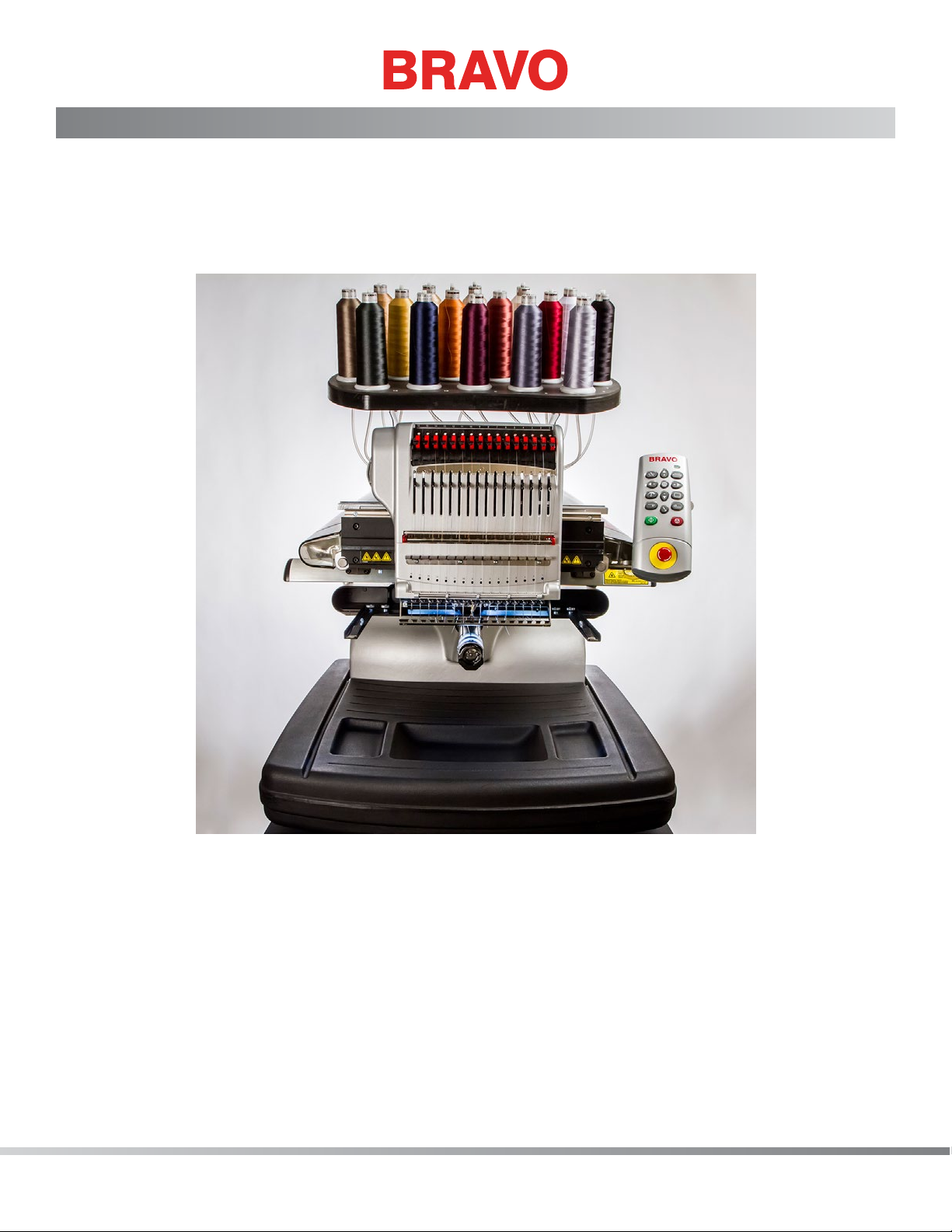
Page 1

Technical Manual
Rev 082115
Page 2

Contents
Table of Contents
Copyright Notice 9
About This Manual 10
Scope of Manual 11
Standard Conventions and Denition of Terms 12
Regulatory Notices 13
Best Maintenance Repair Practices 14
Maintenance Philosophy: 14
Grounding and Static Electricity 17
Machine Orientation 19
Safety Issues 20
Warranty Considerations 21
Explanation of Machine Symbols 22
Keypad Operations 23
Keypad Buttons 26
Trace Button 26
Arrow Up Key (Y-Axis Back) 26
Color Change/Needle Case 26
Arrow Left Key (X-Axis Left) 26
Arrow Right Key (X-Axis Left) 27
Center Key 27
Adjustment Key 27
Arrow Down Key (Y-Axis Forward) 27
Hoop Key 28
Step Back Key 28
Step Forward Key 28
Laser Key 28
Start Button 28
Stop Button 29
Emergency Stop Button 29
LED Indicator 30
Specications 31
Technical Specications 33
Torque Specications 34
2 of 271
Page 3

Software Maintenance Menus 36
Table of Contents
Special Tools and Fixtures 37
General Maintenance 38
Cleaning 38
Lubrication Schedule and Specications 40
Maintenance Schedule 40
Daily Maintenance 42
Weekly Maintenance 43
Monthly Maintenance 45
Quarterly Maintenance 51
Thread Cutter Blade Replacement 61
Centering The Needle Plate 62
Head Up Position Adjustment 63
Mechanical Head-Up Position 63
Adjusting Head-Up (Z-Home) Position: 64
Hook Timing Inspection/Adjustment 65
Rotational Hook Timing Inspection Procedure 65
Needle To Hook Gap Inspection Procedure 67
Adjustment Procedure 67
Thread Clamp Replacement 71
Thread Clamp PCB Replacement 72
Thread Clamp Harness Replacement 72
Laser Light - Adjustment 74
Needle Depth 76
Setting the Needle Depth by Eye 76
Presser Foot Height 77
X/Y Home Adjustment 78
Home Adjustment Procedures: 78
X-Cable Tension 81
Determining if an X-Cable is Set to Required Specications 81
Adjusting an X-Cable that is Tensioned Outside the Required Specications 82
Y-Axis Timing Belt Tensioning 84
Y-Axis Belt Tension Inspection 84
Y-Axis Belt Tension Adjustment 85
When Belt Tensions are Correct 85
Y-Motor Timing Belt Tensioning 86
Inspection and Adjustment 86
3 of 271
Page 4

Z-TIMING: Bottom Center & Head-Up 87
Table of Contents
Bottom Center (Z Timing) 87
Z-Drive Belt Tensioning 92
Inspection and Adjustment 92
Z-Home Adjustment 94
Procedure to Identify the Closest Needle 95
Needle Case Calibration 98
Fine calibration procedure: 98
Rough Calibration Process: 99
Rotary Hook Support Adjustment 101
Inspection Procedure 101
Adjustment Procedure 103
Color Change, Take-Up, Feeder Housing Assembly 105
Replacement Procedure for Entire Color Change/Take-Up/Feeder Assembly: 105
Color Change Linear Actuator Replacement 107
Replacement Procedures: 107
Thread Feeder Gear Replacement 110
Replacement Procedures: 110
Thread Feeder Optical Sensor PCB Replacement 112
Replacement Procedure: 112
Thread Feeder Radial Bearing Replacement 113
Replacement Procedures: 113
Thread Feeder Stepper Motor Assembly 114
Replacement Procedure: 114
Laser Pointer Assembly 116
Replacing the laser assembly: 116
LED Cluster PCB Replacement 118
Presser Foot Assembly Replacement 119
Reciprocator 122
Replacement Procedure 122
Take-Up Lever Cam Replacement 124
Replacement Procedure 124
Z-Drive Repair and Adjustment 127
Z-Drive Belt Replacement and Tensioning 127
Z-Home Sensor PCB Replacement 129
4 of 271
Page 5

Z-Belt Idler Assembly Replacement 131
Table of Contents
Z-Motor Assembly 132
Clearing Thread from Thread Feeder Roller 135
Color Change Spindle Mounting Bracket Replacement 137
Grabber Blade Replacement 139
Needle Case Removal 142
Needlecase Installation 144
Grabber Stepper Motor Replacement 146
Take Up Lever Replacement 147
Thread Feeder (replacement and adjustment) 149
Thread Sensor Assembly Replacement 152
Bobbin Shaft Overhaul 154
Rotary Hook Replacement 156
Main PCB 158
Power Input Assembly Replacement 160
Power Input Assembly Removal: 160
Power Input Assembly Component Replacement: 161
Power Input Assembly Installation: 166
User Interface Assembly Replacement 167
Harnesses 170
Color Change Motor Harness 171
Ethernet Harness 174
Grabber/Threadfeed Motor Harness 176
Grabber/Threadfeed/CC Home Harness 179
Laser Harness 182
LED Cluster Harness 184
Replacement Procedures: 184
Thread Break Harness 188
Z Home Harness 191
5 of 271
Page 6

User Interface Harness 193
Table of Contents
X/Y Home Harness 195
Bearing Block Assemblies 197
X-Beam Assembly 199
X-Carriage Assembly 201
X-Drive Cable Removal 203
X-Drive Cable Installation 205
X-Drive Motor Replacement 209
X-Home Optical Switch Assembly Replacement 212
X/Y Home PCB Replacement 214
Y-Drive Belt Replacement 216
Y-Motor Assembly 218
Troubleshooting 220
Grabber Function Test 221
Final Functional Tests 223
Optical Sensors Test 225
Power Supply Test 226
Servo Motor Resistance Test 229
Stepper Motor Resistance Test 230
Servo Motor Resistance Test 231
Troubleshooting Stepper Motors 232
6 of 271
Page 7

Test Designs 235
Table of Contents
Thread Tension Test 236
Belt Tension Test 237
Long Stitch Test 237
Looping Test 237
Orientation Test 238
Registration Test 238
Small Alphabet Test 238
Thread Break Sensor Test 239
Thread Break Test 239
Trimmer Test 240
Electrical Failures 241
AC Power Failure 241
Color Change Failures 241
LED Cluster Assembly Failures 242
Machine Initialization Failure 242
Mechanical Failures 244
False Thread Breaks 244
Loose/Looping Stitches 244
Needle Breaks 244
Skipped Stitches 245
Thread Breaks 246
Miss-Starts 250
Cap Frame Issues 250
Miscellaneous Problems 251
X-Axis Failures 252
Y-Axis Failures 253
Z-Axis Failures 254
Software Error Messages 255
DSP Command Errors 256
Can’t Initialize Stepper Motors 256
No Trace Data 256
XY Home Not Set 256
Goto Func Error 257
Hoop Center Error 257
Stepper Motor Time Out and Index Errors 257
E-Stop Engaged 258
Servo Motor Errors (Move Time Out, Tracking, and Over Current Errors) 260
7 of 271
Page 8

Critical Measurements 262
Table of Contents
Introduction 262
Needle Drive Stud to Reciprocator Fit 263
Hook Timing 263
Upper Arm to Lower Bed Alignment 263
Needle to Hook Gap 264
Hook to Rotary Support Gap 264
Take-Up Lever Stroke 264
Take-Up Lever Fit to Shaft 265
Take-Up Lever Endplay 265
Cam Follower Preload 265
Pull Force on Take-Up Lever 266
Color Change Lead Screw 266
Color Change Housing Location 267
Bobbin Tension 267
Presser Foot Adjustment at Bottom Dead Center 268
Thread Feed Forward 200 269
Needles 269
Thread Clean Thread Path 270
Z-Belt Tension 270
X-Cable Tension 271
Y-Axis Timing Belt Tension 271
Proper Lubrication of Moving Parts 271
8 of 271
Page 9

Copyright Notice
Table of Contents
© Copyright Melco, 2014
ALL RIGHTS RESERVED. No part of this publication may be reproduced, stored in a retrieval system, or
transmitted in any form or by any means (electronic, mechanical, photocopying, recording or otherwise)
without prior written approval from the author. The author reserves the right to revise this publication
and to make changes in it at any time without obligation of the author to notify any person or organization of such revisions or changes.
All precautions have been taken to avoid errors or misrepresentations of facts, equipment, or products.
However, the manufacturer does not assume any liability to any party for loss or damage caused by errors
or omissions.
The machine technology is protected by - but not limited to - the following patents:
• U.S. 4,955,305
• U.S. 6,823,807
• U.S. 5,603,462
• U.S. 5,832,853
• U.S. 6,445,970 B1
• U.S. 6,732,668 B2
• U.S. 6,729,255
• U.S. 6,871,605
• U.S. D 474,785 S
• U.S. 6,736,077 B2
• CH 693569 A5
• EP 0 666 351 B1
• more patents pending
9 of 271
Page 10

About This Manual
Table of Contents
This manual contains instructions on repairs and adjustments to the embroidery machine, in addition to
other technical information.
If you do not fully understand any information in this manual, you are advised to contact your local au-
thorized technical support provider for assistance.
10 of 271
Page 11

Scope of Manual
Table of Contents
This technical manual is a guide to performing repairs and adjustments that go beyond routine operator
maintenance.
Although these procedures are best understood and performed by professional service technicians in
conjunction with specic factory technical training, much of the information in this manual is a useful
reference for others who might possess appropriate technical aptitude and skills.
Note: This manual is written for individuals with adequate knowledge, Melco certied training
•
or equivalent and experience in the use of tools required. No attempt is made to explain how
to use tools required to make repairs to the machine other than graphical depictions within the
procedures involved.
This technical manual species that certain functions are to be performed only by authorized service technicians. This is because specialized training and/or special tools or xtures are required in order to per-
form the function correctly. Performing repairs to the machine may result in damaged components, poor
machine performance, and potential injury to the technician or operator.
If you do not fully understand any information in this manual, contact technical support for assistance
before performing the procedure. The technical support staff are professional service technicians trained
on this equipment. They have acquired technical expertise through experience and technical training.
Additionally, certied equipment technicians routinely receive up to date servicing information to further
enhance their product knowledge.
This technical manual is presented in six sections:
1. Introduction to the manual and various service requirements
2. General information and specications containing all of the engineering settings and specications
you need to know when adjusting the machine
3. Lubrication schedules and procedures
4. Service and repair - detailed instructions to service and repair the machine
5. Options - maintenance and repair of optional equipment
6. Troubleshooting - a troubleshooting guide for problems commonly encountered with the machine.
11 of 271
Page 12

Standard Conventions and Denition of Terms
Table of Contents
Throughout this manual abbreviations and specic terms may be used. When abbreviations or technical terms are used, they are dened through the use of pop-up hot spots, which opens a dialog box to
explain their meaning. Hot spot text is green and underlined. To access a pop-up hot spot simply click the
underlined word to read its explanation.
Certain procedures in the manual require actions such as pressing a certain key, or typing some letters on
the computer keyboard. The following is a list of some of the more commonly used conventions found in
this manual:
• To indicate a key on the computer keyboard, the key in question is enclosed in brackets, for example: Press the [Enter] key to initiate the application.
• A key on the interface keyboard is represented by a picture of that key.
Attention Styles:
Occasionally in the manual, special attention is required. In these situations, certain images and text styles
are used to attract your attention to a particular message. The following styles are used to denote certain
types of messages.
WARNING!! Situations which may result in personal injury if not performed correctly.
•
CAUTION!! Situations that might result in damage to equipment or property but is not likely to
•
result in personal injury.
IMPORTANT: Situations critical to correct machine operation that is not likely to result in damage
•
to the machine or personal injury.
NOTE: Important information that is signicant, but not likely to result in interference to correct
•
machine operation.
TIP: Helpful information that might make a procedure easier or more efcient.
•
When a reference to a part description is in bold type, that reference is the actual part description as
listed in the machine parts manual. The parts manuals are unique for each machine depending on serial
number and date of build. For part numbers, pictures, and assembly diagrams, refer to the parts manual
issued for that particular machine.
12 of 271
Page 13

Regulatory Notices
Table of Contents
(U.S.) The FCC (Federal Communications Commission) mandates that if a user makes changes or modi-
cations to the machine not expressly approved by the manufacturer, the user’s authority to operate the
machine may be voided.
13 of 271
Page 14

Best Maintenance Repair Practices
Table of Contents
The procedures presented in this manual are to be considered best maintenance repair practices. These
procedures are intended to optimize the performance and durability of your machine. Best maintenance
repair practices are to be performed using the correct tools and xtures while adhering to all safety precautions appropriate for each job.
WARNING!! Personal injury may result if proper precautions are not observed. Remove rings,
•
watches, and any other metallic objects from hands and wrists before servicing the machine.
Remove metallic articles from shirt pockets to prevent them from falling into the machine. Do
not allow loose clothing or long hair contact moving parts of the machine. Under certain conditions of machine failure, the moving parts of the machine may not be controllable by normal
means. At these times, the machine may operate without notice.
CAUTION!! Use extreme care not to drop metallic objects, tools, or other conductive material on
•
the main Printed Circuit Board (PCB) when you have the base cover removed. If you drop such
objects on the main PCB, it can severely damage the electronics which will be very expensive to
repair.
Maintenance Philosophy:
The maintenance philosophy used in this manual is to isolate potential problems within the system to the
smallest practical replacement assembly. Therefore, components are typically not repaired, but rather, a
circuit board or mechanical subassembly may be replaced.
In the process of isolating problems in the machine, the person performing the troubleshooting must also
practice good troubleshooting techniques. Good troubleshooting techniques include, but are not limited
to, guarding against static electricity that can result in further damage to machine components, and only
replacing one part at a time to enable identication of the defective part after the machine is repaired.
WARNING!! Failure to practice Best Maintenance Repair Practices may result in injury to person-
•
nel performing the work and/or damage to the equipment. The warranty is exclusive of, and
may be VOID if poor maintenance practices have caused damage to the equipment.
Dust:
As with any electronics, the worst source for contamination for the PCBs and the Control PCB is dust.
Although great care has been made during the design of the electronics in the machine, dust accumulation may cause failure of the machine if it is allowed to accumulate.
14 of 271
CAUTION!! DO NOT use solvents of any type on the printed circuit boards (PCBs) or sensors.
•
Solvents will damage the electronic components. Use only compressed air to clean these items.
Page 15

Using compressed air, blow the dust away from sensors and off the PCB’s in the machine. In addition,
Table of Contents
minimize dust accumulation cleaned on all exposed surfaces. Excessive dust will reduce the useful life
span of the machine.
Sensors should be cleaned with dry, compressed air during each of the lubrication cycles. Dust accumulation in the base around the control PCB should be blown out every month or whenever the base cover is
removed for any type of maintenance.
Liquid Cleaning Compounds:
Never spray liquid cleaning compounds directly onto the machine, especially if it is turned on or connected to an electrical supply outlet. Always spray cleaning compounds onto a rag and wipe the machine
clean. Liquid cleaners can, if sprayed directly on the machine, get onto electrical components and short
them out. Optical sensors are very sensitive and may be damaged by liquid cleaning compounds.
Obstructions:
Obstructions of machine movements can cause severe damage. Obstructions include things like fabric
getting caught in the gears, loose hardware left inside the machine, thread accumulation around the
grabber blade, Velcro, and anything that hinders the machine’s moving parts. It is very important to clear
obstructions from any subsystem immediately before damage or excessive wear occurs.
Use Proper Parts For The Job
It is very important that you use the proper parts for the job, especially needles. Refer to the Operator
Manual for information on needle selection. Using the wrong needle will increase the frequency of frays
and thread breaks and will decrease performance of the machine.
Avoid using substandard substitute parts on the machine. Always use manufacturer distributed parts or
better to ensure superior quality output of your machine. When considering buying substitute parts, i.e.,
hardware, it is strongly recommended that you consult Technical Support and obtain the specications to
ensure that you get the equivalent grade or better parts.
Use The Correct Tools When Making Repairs
Always use the correct tools when making repairs or performing maintenance on the machine. No attempt has been made in this Manual to explain what tools to use. It is assumed that the person who
makes repairs or performs maintenance on the machine has the proper technical aptitude and training to
allow them to do so. Using tools incorrectly or using the wrong tools can cause damage to the machine
and result in personal injury.
The use of poor quality tools such as multimeters and mechanical measuring devices can produce unpredictable and often unsatisfactory results. Always purchase tools for repair or maintenance on the machine
that are of standard design and professional quality. You may if desired, consult Technical Support for
assistance in recommending such tools as multimeters and measuring devices before you purchase them.
15 of 271
Page 16

Drive Belt Tensions:
Table of Contents
CAUTION! Damage to the machine may result if belt tensions are improperly adjusted. All drive
•
belts require special procedures and tools for setting the proper tensions. If the tension adjustments are made without using the proper procedures and tools (and without training in some
cases), poor performance, excessive wear, damaged components, personal injury, and voided
warranty may result.
Scheduled Maintenance:
Scheduled maintenance is lubrication, cleaning, measurements, and inspections that are specied on a
periodic schedule.
Scheduled maintenance is prescribed in the operator manual for the machine. Failure to perform scheduled maintenance will result in poor performance and eventual failure of the machine. In addition, failure
to perform the maintenance prescribed in the operator manual can affect warranty protections.
Lubrication:
Lubrication should be done whenever a part is replaced or repaired and as prescribed according to the
Lubrication Specications. When applying lubricants to any parts, use only the approved lubricants and
application methods specied in the Lubrication Specications.
CAUTION! Damage to the machine will result if inadequate or excessive lubrication is applied
•
to machine parts. Failure to adhere to lubrication specications will result in premature wear,
poor performance, and potential warranty issues.
Torque Measurements:
Apply proper torque to all screws, bolts, and nuts or similar parts used in the machine. Torque specications are provided for a reason. They have been developed from years of experience with the parts
involved. Avoid guessing at the torque applied to a part and measure it, especially where measurement is
specied.
CAUTION!! Inadequate torque can result in premature failure of the part involved, usually
•
causing it to come loose. Excessive torque usually results in stress to the part that will not always be detectable. The part can fail later during machine operation and can cause catastrophic machine failure.
16 of 271
Page 17

Grounding and Static Electricity
Table of Contents
WARNING!! It is very important that the power cord is plugged into a properly wired electri-
•
cal outlet. Failure to have a properly wired outlet may result in damage to the equipment and
personal injury. It is recommended that a licensed electrician be consulted to ensure that the
electrical outlet is properly wired and grounded. If a properly wired electrical outlet is not used
for the source supply voltage to the system, electrical failures may result.
Static Electricity:
As with all computerized equipment, your machine is sensitive to static electricity. Any time work is
performed inside covered areas of the embroidery machine, the person performing the work must use
a static grounding strap or take adequate steps to dissipate static build-up prior to touching electronic
components.
WARNING!! Failure to use a grounding strap, or failure to practice other good maintenance/
•
repair techniques may cause damage to the machine and possible personal injury.
CAUTION!! Unless otherwise specied within these procedures, DO NOT disconnect the
•
electrical supply input cord from the machine or the electrical input source outlet. Doing so will
remove the ground connection needed to dissipate the electrical static build-up prior to working on the internal components in the machine. Always make contact with the exterior metal
portion of the machine for about one minute to dissipate any electrical static build-up in your
body before touching any electronic component of the machine, especially the main board.
Grounding Strap Use:
A grounding strap should be connected properly to ensure that static charge on the person’s body is neutralized to the chassis ground of the embroidery machine when working in the electronic areas under the
covers. Proper connection is provided at any bare (unpainted) metal surface or any other surface (such as
a ground screw head) that is known to be an earth ground. If a ground strap is not used or is not available, touch the chassis for about a minute to dissipate any static build-up before you touch any electronic
component inside the machine (with the machine turned off and the power input cord connected to an
electrical outlet).
WARNING!! DO NOT attempt to use any grounding strap that is not specically designed for
•
static use. A “straight-wire” grounding device (one without built-in resistance) will place the
operator in danger of exposure to dangerous voltages. It is recommended that the static strap
be checked during daily use for proper resistance protection.
17 of 271
Page 18

CAUTION !! Use extreme care not to damage the cable and protective coating during assem-
Table of Contents
•
bly. If the protective coating is damaged, the cable will wear out very fast impacting the quality
of the sew outs.
18 of 271
Page 19
Machine Orientation
Table of Contents
The references in the manual to certain sections of the machine are oriented as if you were facing the
front of the machine as shown below. Example: The “left” arm cover is on the left side of the machine
when you face it from the front, but is on the right side if you face it from the rear. The part however, is
called the “left” arm cover since it is installed on the left side, oriented as you face the machine from the
front.
Left Side Right Side
The left and right sides of the machine are oriented just as if you were facing it from the front side of the
machine directly.
The rear of the machine refers to the entire back side of the machine.
The front part of the machine refers to the entire front section of the machine.
The upper arm assembly, lower arm assembly, needlecase, user interface, and thread tree refer to the
entire individual assembly and associated components.
19 of 271
Page 20

Safety Issues
Table of Contents
Voltages
WARNING!! Lethal voltages exist inside the power supply unit, at the back side of the electrical
•
supply input connector, and in the wires between the two. If you plan to do any work with any
of these components, turn the power switch off and disconnect the electrical input supply cord
from the machine.
WARNING!! DO NOT disassemble the power supply unit. It contains no customer or eld ser-
•
viceable parts. The internal components in the power supply unit may contain dangerous voltages even when the power is disconnected. Disassembling the power supply can cause severe
injury resulting from electrical shock, and may void the warranty.
WARNING!! DO NOT operate the machine with the lower rear cover removed, except when
•
indicated by the instructions in this manual. Operating the machine without the covers creates
a risk of severe electrical related injury.
Hazardous Material Notices:
WARNING!! The lubricants specied in this Manual contain known carcinogens. Do not allow
•
lubricants to come into contact with your eyes, mouth, or nose. Always wash your hands thoroughly after performing lubrication procedures.
WARNING!! When using solvents to clean components in the machine, always ensure adequate
•
ventilation. Allow all solvents to completely evaporate before turning the machine back on to
prevent shorting out electrical components. Vapors from most solvents are both toxic and ammable. Dispose of rags soaked with solvent properly.
Moving Parts:
WARNING!! Do not operate the machine without the covers being installed. Moving parts can
•
cause crushing and pinching injuries. In addition, fabric and other materials can get caught in
the moving belts and gears and damage the machine.
20 of 271
WARNING!! Do not attempt to pull on or trim threads near moving needles. This can result in
•
painful injury.
Page 21

Warranty Considerations
Table of Contents
Many areas of maintenance in this manual require factory trained personnel to ensure proper service. Any
service that is improperly performed may void the warranty.
Items that are marked “...should be done by an authorized service technician” should be performed by
a repair technician that has been authorized by the manufacturer. Performance of these items requires
special training and/or tools and involves a great deal of difculty. If technician only items are repaired/installed incorrectly, it will void all applicable warranty considerations and can cause further damage to the
machine.
The use of other than manufacturer issued or recommended parts, hardware and lubricants can affect
warranty considerations. It is strongly recommended that you use only products from the manufacturer
or products recommended by technical suppport on your embroidery machine(s).
21 of 271
Page 22

Explanation of Machine Symbols
Table of Contents
These labels are placed on the machine at specied locations to warn you of certain machine hazards.
Caution!!
Indicates a machine component will move. Keep clear!
Shock Hazard. No user replaceable parts behind this label. Do not open!
Moving gears. Keep clear!
Vertical Pinch Point. Keep clear!
Horizontal Pinch point. Keep clear!
Needle Pinch point. Keep clear!
22 of 271
Page 23

Keypad Operations
Table of Contents
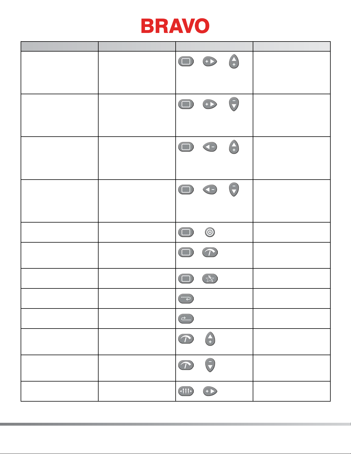
Function Press these key(s) Keypad Pictures Notes
To Start Sewing Start
Press the stop key to
stop sewing
To Stop Sewing Stop
Cuts power to the
motors.
Emergency Stop
E-Stop
Select Machine Center
To move the hoop up Hoop + Down Arrow
To move the hoop down Hoop + Up Arrow
To move the hoop left Hoop + Right Arrow
To move the hoop right Hoop + Left Arrow
+
+
+
+
Press the start key to
start sewing
To release, turn a quarter turn in the direction of the arrows and
release.
Selects the machine
to be displayed in the
software
Always trace after
moving
Always trace after
moving
Always trace after
moving
Always trace after
moving
23 of 271
Page 24
Function Press these key(s) Keypad Pictures Notes
Table of Contents
To move the hoop down
and to the left (moves
Hoop + Right + Up
+ +
Always trace after
moving
needle position up and
to the right in relation to
the hoop)
To move the hoop up
and to the left (moves
Hoop + Right + Down
+ +
Always trace after
moving
needle position down
and to the right in relation to the hoop)
To move the hoop down
and to the right (moves
Hoop + Left + Up
+ +
Always trace after
moving
needle position up and
to the left in relation to
the hoop)
To move the hoop up
and to the right (moves
Hoop + Left + Down
+ +
Always trace after
moving
needle position down
and to the left in relation to the hoop)
To center the current
Hoop + Center
hoop
Clears and ignores
Hoop + Adjustment
the “Trim Required”
message.
To trace the design Hoop + Trace
+
+
Center hoop before
beginning to sew
This indicates to the
machine that no thread
is through the cloth.
Repeat to trace again
To frame back one stitch
at a time
To frame forward one
stitch at a time
To increase the sewing
speed
To decrease the sewing
speed
To move the needlecase
to the right
24 of 271
Hold down the Frame
Back key
Hold down the Frame
Forward key
Adjustment + Up Arrow
Adjustment + Down
Arrow
Needlecase key + Right
Arrow
+
+
+
+
Press the stop key to
stop framing
Press the stop key to
stop framing
The speed will increase
50 spm each time
pressed
The speed will decrease
50 spm each time
pressed
Page 25
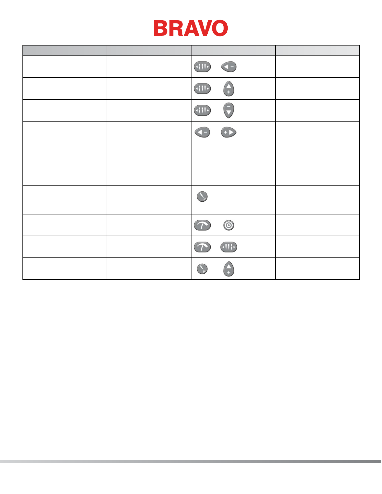
Function Press these key(s) Keypad Pictures Notes
Table of Contents
To move the needlecase
to the left
To color change to the
next color
To color change to the
previous color
Return to Previous Stitch Left Arrow + Right
To turn the laser on Laser
Toggle front grabber Adjustment + Center
Trim Immediate Adjustment +
To manually feed thread Laser + Up Arrow
Needlecase key + Left
Arrow
Needlecase key + Up
Arrow
Needlecase key + Down
Arrow
Arrow
Needlecase
+
+
+
+
+
+
+
If a hoop has been
moved during the sewing of a design, pressing
this combination will
move the hoop back to
the position of the most
recent stitch to sew.
This will allow you to
see the active needle
position
Toggle to thread the
needle
Manually feeds thread
on the current needle
25 of 271
Page 26

Keypad Buttons
Table of Contents
Trace Button
The trace button is used to trace the design, a method used to help the operator determine if the design
is properly centered and ts within the hoop used.
+ To trace a design, press the Hoop button and the Trace button.
Arrow Up Key (Y-Axis Back)
+
+ The hoop key and the arrow up key performs a manual jog, moving the stitch point to the top
of the design. The hoop actually moves towards the front of the machine.
+
The needle case moves to the next color.
The sew speed (stitches per minute) is increased.
Color Change/Needle Case
When used in conjunction with the arrow keys, the machine will perform a color change function (moving the hoop) or move needle case left or right.
+
+
+
+
Needle case to the left
Needle case to the right
Color change to next color
Color change to the previous color
Arrow Left Key (X-Axis Left)
+
the right.
The machine performs a “manual jog”, moving stitch point left. The hoop actually moves to
26 of 271
+
The needlecase moves to the left.
Page 27

Arrow Right Key (X-Axis Left)
Table of Contents
+ The machine performs a “manual jog”, moving stitch point right. The hoop actually moves to
the left.
+
The needle case moves to the right.
Center Key
+ When used with the hoop key , the machine moves to hoop center.
+ When used with the adjustment key, the machine toggles the safety grabber in and out. This
is helpful in tucking threads back into the trap behind the needles for moving the grabber out of the way
for changing of threading a needle.
Pressing the Center key will select the machine to be displayed in the software.
Adjustment Key
The adjustment key is used to adjust the thread feed or the machine speed.
+ Adjustment key and the Arrow Up key increase the sew speed (stitches per minute).
+ Adjustment and Arrow Down key decrease the sew speed (stitches per minute)
+ Adjustment and the Center key toggles the safety grabber in and out (for needle threading
access)
Arrow Down Key (Y-Axis Forward)
+
+ The Arrow Down key with the Hoop key performs a manual jog, moving the stitch point towards the bottom of the design. The hoop actually moves towards the back of the machine.
The Arrow Down key the Needle Case key moves to the previous color.
+ The Arrow Down key with the Adjustment key decreases the sew speed of the machine.
27 of 271
Page 28

Hoop Key
Table of Contents
The Hoop key is used to move the position of the needle in relation to the hoop.
+ The Hoop Key and the Arrow Up key move the needle position up, towards the top of the
hoop (moves the hoop forward, toward the front of the machine.
+ The Hoop Key and the Arrow Down key move the needle position down, towards the bottom
of the hoop (moves the hoop towards the back of the machine).
+
to the right)
+ The Hoop Key and the Arrow Right key moves the needle position to the right (moves the
hoop to the left)
+ The Hoop Key and the Center key moves the hoop to hoop center position
The Hoop Key and the Arrow Left key moves the needle position to the left (moves the hoop
Step Back Key
The step back key moves the machine backwards on the design (to a lower numbered stitch point).
This allows the operator to restitch a certain portion of a design if needed.
Step Forward Key
The step forward key moves the stitch point in the design forward (to a higher numbered stitch
position).
Laser Key
Press and hold the laser key to turn the laser on. The laser stays on as long as the key is pressed.
+ You can also press and hold the laser key , then press the up arrow to manually feed thread
on the current needle. This function is useful when threading a needle because it can be used to supply
more thread (replacing the need to lift the pinch roller and pull out more thread).
Start Button
Pressing the start button while the machine is not running and is at the start of a design will start the
sewing of the design.
28 of 271
Page 29

Pressing the start button while the machine is stopped will re-start the machineat the stitch number
Table of Contents
where the machine was stopped.
Stop Button
The stop button stops the machine operation but does not disconnect electrical supply to the motors and
electronics.
Do not confuse this button with the Emergency Stop button. The machine can still start if there
•
is a machine fault somewhere. The stop button does not disconnect power from the motors or
internal components.
Emergency Stop Button
The emergency stop button breaks the electrical circuit to all of the motors to prevent its operation.
29 of 271
Page 30

LED Indicator
Table of Contents
The Status Indicator LED is illuminated when the machine is turned ON.
The LED color and whether it is blinking indicates the machine status or if it has a fault.
Status Light Condition Denition Action to Take
Green (blinking) Machine is on, but no RSA les
Start software, check connections
loaded yet
Green (continuous) Machine is on and ready for
operation
Red (blinking slow) Indicates a thread break Re-thread the needle with thread
break
Red (blinking fast) Indicates the machine has run
Replace the bobbin
out of bobbin thread
Red (continuous) Indicates the machine is in E-Stop
engaged mode
Release the red emergency stop
button
30 of 271
Page 31

Specications
Table of Contents
For indoor use only
Operating Software Bravo OS Lite Bravo OS Flex
Type/# of Heads Upper Arm-Lower Arm/1
Modular
Upper Arm-Lower Arm/1 to 4
Modular
# Needles 16 16
Maximum Tubular Frame Size
360mm x 300mm (14.2”x 11.8”) 426mm x 430mm (16.8”x 16.9”)
(XxY)
Maximum Sew Field/Tubular
322mm x 267mm (12.7”x10.5”) 397mm x 267mm (15.6”x10.5”)
Frame (XxY)
WA Cap Frame N/A 360mm x 82mm (14.2” x 3.2”)
Conventional Cap Frame 152mm x 70mm (5.9”x 2.75”) 152mm x 70mm (6.0”x 2.8”)
Min/Max Sew Speed 300-1000 spm 300-1100 spm
Stitch Length Range Only Limited by Hoop Size Only Limited by Hoop Size
Machine Conguration 1 individual machines, connected
by Ethernet
Self-Diagnostics Capability Retrieves relevant machine data
for troubleshooting
Up to 4 individual machines, con-
nected by Ethernet
Retrieves relevant machine data
for troubleshooting
Simplied User Interface Step by Step Guide Software Step by Step Guide Software
Design Memory Limited only by hard drive, Max
le size 500k
Limited only by hard drive, Max
le size 500k
Pre-Sew Trace Laser Laser
Needle to Garment, Garment to
Laser Positioning System Laser Positioning System
Hoop Position
Thread Feed Technology Patented Acti-Feed Patented Acti-Feed
Thread Break Detection Upper & Lower Electronic Force
Gauge Sensor
Upper & Lower Electronic Force
Gauge Sensor
Automatic Stitch Backup Yes Yes
Automatic Trimmer Yes Yes
Lighting Type Cold Bright Cold bright LED Cold bright LED
Power Supply (V) 90-260V (Single Phase, 50/60
HZ, 4A), Class I (Grounded)
Power Consumption (W) Typical: 200 Watts Max: 650
Watts
90-260V (Single Phase, 50/60
HZ, 4A), Class I (Grounded)
Typical: 200 Watts Max: 650
Watts
Temperature Range 15-40° C 15-40° C
Humidity Max 85% Relative Humidity Max 85% Relative Humidity
Installation Category
II II
(overvoltage)
Pollution Degree 2 2
31 of 271
Page 32

Operating Software Bravo OS Lite Bravo OS Flex
Table of Contents
Motor Type(s) Servo, Stepping Servo, Stepping
Motor Capacity (kV) X and Z: 100 Watts Y: 250 Watts X and Z: 100 Watts Y: 250 Watts
Machine Construction Material Aluminum Aluminum
Physical Specications with Cart
Width 724mm (28.5”) 724mm (28.5”)
Height 1541mm (60.7”) 1541mm (60.7”)
Depth 944mm (37.2”) 944mm (37.2”)
Weight 95.4kg (210.3 lbs) 95.4kg (210.3 lbs)
Physical Specications without Cart
Width 724mm (28.5”) 724mm (28.5”)
Height 907mm (35.7”) 907mm (35.7”)
Depth 737mm (29.0”) 737mm (29.0”)
Weight 75kg (165lbs) 75kg (165lbs)
32 of 271
Page 33

Technical Specications
Table of Contents
The following is a list of various tension and force specications for your machine. See the Critical
Measurements section for other machine specications that are not listed below.
Specication BRECO Meter Measurement Force Gauge Measurement
X Drive Cable Tension 145 ± 5 Hz at 350±2.5 mm
between center of rst and rear
pulleys measured from right side
10.5 ± 0.5 lbs [4.76 ± 0.23
kg] using X-Cable Tensioning
Procedure
of machine only.
Left and Right Y-Drive Belt
Tensions
45-50 Hz with beam to the back
at a dead stop
8.1 ± 0.3 lbs [3.67 ± 0.14
kg] using Y-Axis Timing Belt
Tensioning procedure
Y-Motor Belt Tensioning 100-120 Hz 7.5 - 9.5 lbs [3.4 - 4.3 kg] using
Y-Motor Timing Belt Tensioning
procedure
Z-Motor Belt Tensioning 72-78 Hz 6.8 ± 0.3 lbs [3.08 ± 0.14 kg]
measured using Z-Drive Belt
Tensioning procedure
X-Carriage Drag (Friction) 5.5-9.5 lbs, Disconnect motor
from control board
Y-Carriage Drag (Friction) 10-25 lbs [4.5-11 kg], Disconnect
motor from control board
The following lists the X and Y home positions attained when the “Set Home” function is initiated on the
machine.
X Home: centered within ± 0.015 inches [0.4 mm]
Y Home: carriage mounting holes positioned 7.09 ± 0.015 inches [180 ± 0.4 mm] (relative to needle
plate hole)
33 of 271
Page 34

Torque Specications
Table of Contents
The following chart depicts the torque specications for all screws and nuts used in the machine. They
should be followed unless indicated otherwise in this manual (i.e., screws going into plastic materials
require lower torque).
Note: Reduce torque specications when attaching optical sensors by 10% to prevent damage
•
to the sensor housing. Use minimum torque when screwing into or clamping plastic surfaces.
Size Min Max Min Max
In-lb In-lb N-m N-m
Zn Plated, Property Class 8.8, Socket Head Screws (PN: 010170-XX, 010171-XX, 010172-XX, 010174XX, 010175-XX)
M2.5 5 7 0.66 0.80
M3 10 13 1.2 1.4
M4 23 26 2.6 3.2
M5 46 56 5.1 6.3
M6 79 96 8.9 10.9
M8 190 234 21.6 26.4
Zn Plated, Property Class 4.5, Slotted and Phillips Machine Screws (PN: 006558-XX, 004262-XX,
009862-XX, 009863-XX)
M2.5 1 2 0.19 0.23
M3 3 4 0.40 0.48
M4 8 10 0.92 1.12
M5 16 19 1.8 2.2
M6 27 33 3.1 3.7
M8 45 55 5.1 6.3
Black Oxide, Property Class 12.9, Black Socket Head Screws (PN: 01922-XX, 67018-XX, 671852-XX,
671686-XX, 671687-XX, 003183-XX)
M2.5 10 12 1.2 1.4
M3 18 22 2.1 2.5
M4 43 51 4.7 5.8
M5 83 100 9.4 11.4
M6 144 175 16.2 19.8
M8 345 418 38.7 47.3
Set Screws, Property Class 45H (PN: 10188, 01962-XX, 005034-XX, 001960-XX, 10635-XX,
001971-XX)
M3 4 5 0.45 0.55
M4 8 10 0.90 1.10
34 of 271
Page 35

Size Min Max Min Max
Table of Contents
M5 24 29 2.7 3.3
M6 40 48 4.5 5.5
M8 80 97 9 11
Zn Plated, Property Class 8.8, Low Prole Socket Head Screws
PN: 30750-XX
M4 23 28 2.61 3.19
Black Oxide, Property Class 10.9, Flat Head Socket Screws (PN: 001935-XX, 007443-XX)
M3 15 19 1.73 2.11
Zn Plated, Property Class 10.9, Flat Head Socket Screws (PN: 011197-XX, 011198-XX)
M4 34 40 3.77 4.61
M5 65 78 7.29 8.91
Zn Plated, Property Class 12.9, Flanged Socket Head Screws (PN: 30790-XX)
M4 40 48 4.45 5.45
Stainless Steel, Property Class 10.9, Button Head Cap Screws (PN: 011161-XX, 011162-XX, 011163-XX)
M3 15 19 1.73 2.11
M4 34 40 3.77 4.61
M5 65 78 7.29 8.91
Zn Plated, Property Class 04, Metric Hex Nuts (PN: 680430-XX) (Torque based on screws they attach to)
M4 23 28 2.6 3.2
M5 46 56 5.2 6.3
Machine Specic and Custom Hardware
Self Tapping Plastic
8 10 0.9 1.10
DURO Screw (PN:
30737-01)
M6 Lock Nut (PN:
005284-01)
M4x0.7 Nylock Nut
(PN: 003573-04)
Install nut until it makes contact with the spring washer, then turn nut another
half turn.
No torque specication for this nut. Turn nut until specied belt tension is
achieved.
35 of 271
Page 36

Software Maintenance Menus
Table of Contents
In order to access the maintenance menus in the software, the machine must be turned on and software
must be loaded and launched.
Figure 1 - Software Main Menu
To access the maintenance menu, select the “Tools>Maintenance” from the main menu. The screen below will open.
36 of 271
Figure 2 - Maintenance Menu
Page 37

Special Tools and Fixtures
Table of Contents
The following xtures and special tools are required to perform certain procedures and repairs described
in this manual:
• Fixture, Y-Belt Tensioning (PN: 32108)
• Force Gauge (0-40 lbs.) (PN: 995595-01)
• Force Gauge (0-10 lbs.) (PN: 995591-01)
• Universal Force Gauge Adapter (PN: 32498)
• Head Timing Dial Indicator Gauge (PN: 32453-01)
• Head Timing Adaptor Fixture (PN: 33065)
• 3 lb. Weight (PN: 32434)
• Hook Retaining Finger Gauge (PN: 009027-01)
• Take-Up Lever Timing Fixture (PN: 32413)
• Needle Depth Fixture (PN: 32650)
• Fixture, Z Home Flag (PN: 32980)
• Pin, Gauge, Thread Feed Gear (PN: 32996)
• Gauge, Height, Take-Up Lever (PN: 33017)
• 12 Gram Weight (PN: 10082)
• Metric Ruler
• Feeler Gauge Set
All of the above xtures can be ordered through the manufacturer.
It is strongly recommended that the xtures recommended in this manual are used. Making adjustments
without the proper tools and xtures can result in poor performance or damage to the machine. The ma-
chine is dependent on proper maintenance and adjustment in order to produce high quality embroidery.
37 of 271
Page 38

General Maintenance
Table of Contents
This section describes the procedures involved in maintaining your machine. This section is very important, because maintenance is essential to the performance of your machine.
Cleaning
It is very important that you clean your machine regularly. Dust and lint accumulation can damage both
electrical and mechanical systems.
Exterior Surfaces
Clean outer surfaces once per month with a soft, clean cloth, a mild detergent and water. Wring out the
cloth before wiping the surfaces. Do not get water or any other uids inside the machine or on any of
the working mechanical surfaces.
If an accidental spill occurs, turn the machine off then wipe up excess uid with a clean dry cloth and
allow the machine to dry completely before turning the power on.
Interior Surfaces (PCB)
The main PCB can be damaged by dust accumulation. It is important that you periodically remove this
accumulation. To do so, complete the following steps:
CAUTION!! Before proceeding, turn the machine off, but leave it plugged in.
•
1. Remove the base cover. You will see the EMI shield covering the main PCB.
2. Remove the screw(s) that hold the EMI shield in place.
38 of 271
Page 39

3. Carefully lift the EMI shield from the main PCB. If required, disconnect the fan connector from the
Table of Contents
main PCB.
CAUTION!! Be careful not to drop metallic hardware or tools onto the Main PCB while it is
•
exposed. Doing so can result in severe damage to the electronics that might be expensive to
repair.
4. Use any compressed air labeled as ESD safe (and labeled for use on electronic components) to
blow any accumulated dust out of the base interior. When doing so, do not touch the main PCB.
Some compressed air brands have a liquid accelerant that is discharged from the container while blowing dust off the machine. Always allow any liquid discharge to completely evaporate before turning the
machine back on.
5. Carefully place the EMI shield over the main PCB and re-install the screws.
6. Replace the base cover before turning the machine back on.
Rotary Hook and Trimmer Assembly area
Lint and dust can build up in the trimmer assembly and the rotary hook. Clean this at least once per day.
1. Turn off the machine.
2. Remove the needle plate by removing the two screws on the underside of the extrusion.
3. Clean the exposed area with canned or compressed air.
Note: Excessive thread or lint buildup may require removal or disassembly of the trimmer.
•
You should also frequently check this area for loose thread.
If you are frequently performing applications that require you to use adhesive spray, it is recommended
that you clean the rotary hook area at least once a day with a lightweight lubricant spray (such as WD-
40). To do this:
1. Turn off the machine.
2. Remove the needle plate by removing the two screws on the underside of the extrusion.
3. Clean the exposed area with canned or compressed air.
4. Spray the exposed area with a lubricant spray.
5. Turn the machine back on, then rotate the hook all the way around a couple of times.
6. Spray the exposed area with canned or compressed air again.
7. Re-install the needleplate.
39 of 271
Page 40

Lubrication Schedule and Specications
Table of Contents
Tools and supplies needed for these procedures are provided in your operator’s kit.
Using the correct lubricants properly and when specied by scheduled maintenance is critical to the
operation of the machine. Failure to use the proper lubricants as specied can shorten the usable life of
internal components and can void the warranty. Using the wrong lubricants can adversely affect your
machine. The recommended and authorized lubricants to be used on the machine are specied below:
Part Number: Part Name Comments
761003-01 Oiler, 3/4 oz. bottle Sewing Machine Oil
32078 Grease, EMB-Polymer, 8 oz bottle Polymer Light Grease
34463 Grease, HP, 8 oz bottle High Performance Grease
Maintenance Schedule
The following table summarizes the lubrication points and schedule for your machine. The table also lists
which type of lubrication you should use for each lubrication point.
Please note that these schedules are meant to be used as guidelines. Depending on many circumstances
(such as environment, garment types sewn on, etc.), you may need to lubricate your machines more or
less frequently. Follow a lubrication schedule that best ts your needs to take care of your machine(s).
WARNING! Do not attempt to lubricate the machine while it is in operation.
•
Important: The color change lead screw is lubricated for life and should NEVER be lubricated by
•
the user or a technician.
Daily Maintenance
Lubrication Point(s) Lubrication Used
Rotary Hook Sewing Machine Oil
Weekly
Lubrication Point(s) Lubrication Used
Needle Drive Sewing Machine Oil
Left Upper V-Rail Sewing Machine Oil
Right Upper V-Rail Sewing Machine Oil
Oil Needle Bars (Lower) Sewing Machine Oil
Oil Needle Bars (Upper) Sewing Machine Oil
40 of 271
Page 41

Monthly
Table of Contents
Lubrication Point(s) Lubrication Used
X-Drive Rails HP Grease
Y-Bearing Blocks Sewing Machine Oil
X-Cable Tension (Test)
Grabber Eccentric HP Grease
Quarterly
Lubrication Point(s) Lubrication Used
Take-Up Lever Cam, Presser Foot Cam Follower, &
Right Needle Bar Guide
Presser Foot Cam & Left Needle Bar Guide HP Grease
Thread feed Rollers and Pinch Rollers EMB Grease
HP Grease
Yearly
Lubrication Point(s) Lubrication Used
Wide Angle Driver HP Grease
The following belts should be checked once a year: Y-Axis Timing Belt, and Z-Drive Belt. You can either
have a Service Technician check these belts for a charge, or you can perform these checks yourself. To
perform these checks, you will need to purchase the following tools / xtures and follow the procedures
in this Technical Manual.
• Fixture, Y-Belt Tensioning (PN: 32108)
• Force Gauge (0-10 lbs.) (PN: 995591-01)
• Universal Force Gauge Adapter (PN: 32498) see Y-axis timing belt Tensioning , Z-drive Belt
Tensioning sections
CAUTION!! Some of the lubrication procedures instruct you to remove the right/left front cov-
•
ers. Do not turn the machine off, then on again when either of these covers is removed. This
will cause the machine to color change, which will cause the needle bars to fall out. Do not
move the needlecase at all when either of the front covers is removed. If you proceed without
this cover damage to your machine will occur and a service call will be necessary.
Disclaimer: The manfacturer will not be held responsible for any damage to the machine from
•
not performing this step.
41 of 271
Page 42

Daily Maintenance
Table of Contents
Rotary Hook
The rotary hook should be oiled approximately every 4-5 hours of solid running. This will keep the machine running smoother, quieter, and prevent thread breaks.
WARNING!! Never attempt to remove or insert the bobbin with the machine is in operation.
•
1. If you have a product on the machine, please remove it to avoid oil spots.
2. Remove the bobbin case. It can be removed from the lower arm of the machine by locating the
release lever on the bobbin case.
3. Pull forward on this lever until the case is free from the machine.
• This would also be a good time to clean and test the tension the bobbin case.
4. Clean the rotary hook and trimmer area with a brush or canned air.
a. Keeping this area clear of lint and debris will help ensure proper trimming and reduce thread
breaks.
5. Using a small oiler bottle, apply one (1) drop of sewing machine oil to the hook oiling area. This
area is highlighted in green in the photograph.
42 of 271
Page 43

6. This is now a good time to clean, rethread, and Insert the bobbin and case into the machine with
Table of Contents
the pigtail facing up. Push on the bobbin case until it snaps into place.
7. Trim the thread to 2-3 inches.
This completes the hook maintenance procedure.
Weekly Maintenance
WARNING!! If you currently have a hoop or clamping system on the machine, please remove it.
•
Failure to fully remove a clamping system can result in damage to the machine.
Needle Drive
1. Color change to Needle 16.
2. Go to “Tools>Maintenance>Head Timing Tab”.
3. Go to “Top Center”
4. Using a small oiler bottle, put twenty-ve drops (25) of sewing machine oil in the oiling change as
shown in the image.
Note: You may have to add a few drops and wait before adding more to prevent the channel
•
from overowing.
5. After adding the oil, wait ten minutes before continuing.
6. In the Head Timing Tab, go to “Head Up”.
43 of 271
Page 44

Left Upper V-Rail
Table of Contents
7. Using a piece of lint-free cloth, wipe clean both the front and back surfaces of the upper v-rail on
the LEFT side of the needlecase.
8. After cleaning the v-rail, use a small oiler bottle to apply a drop of oil each to the front and the
back surfaces of the v-rail. Apply the oil close to the needlecase.
Right Upper V-Rail
9. Color change to needle #1.
10. Using a piece of lint-free cloth, wipe clean both the front and back surfaces of the upper v-rail on
the RIGHT side of the needlecase.
11. After cleaning the v-rail, use a small oiler bottle to apply a drop of oil each to the front and the
back surfaces of the v-rail. Apply the oil close to the needlecase.
Oil Needle Bars (Lower)
12. Using a small oiler bottle, apply one (1) drop of sewing machine oil to each of the sixteen (16)
needle bars through the hole in the needlecase as shown in the image.
44 of 271
Page 45

Oil Needle Bars (Upper)
Table of Contents
13. Using a small oiler bottle, apply one (1) drop of sewing machine oil to each of the sixteen (16)
needle bars by guiding the oiler applicator through the vertical slots of the needlecase cover just
below the take up lever arms as shown in the image.
14. Close out of the Head Timing Tab.
This completes the weekly maintenance procedure.
Monthly Maintenance
X-Drive Rails
WARNING!! If you currently have a hoop or clamping system on the machine, please remove it.
•
Failure to fully remove a clamping system can result in damage to the machine.
1. Move the x-beam all the way forward and all the way to the left using the hoop and the arrow
keys on the keypad.
2. Remove the end cap cover on the right side of the x-beam as shown in the image.
3. Wipe any lint, dust, and old grease from the front and back steel rails inside the x-beam as shown
in the image.
45 of 271
Page 46

4. Using a clean piece of cloth, apply a thin lm of HP grease to the front and back steel rails inside
Table of Contents
the x-beam as shown in the image.
5. Replace the end cap cover that was previously removed.
6. Remove the end cap cover on the left side of the x-beam as shown in the image.
7. Wipe any lint, dust, and old grease from the front and back steel rails inside the x-beam as shown
in the image.
8. Using a clean piece of cloth, apply a thin lm of HP grease to the front and back steel rails inside
the x-beam as shown in the image.
9. Replace the end cap cover that was previously removed.
10. Press the hoop and the center key on the keypad of the machine to move the arms back to center.
46 of 271
Page 47

Y-Bearing Blocks
Table of Contents
11. Color change to move the needle case to needle #16.
12. Using a 3mm Allen wrench, loosen and remove the three (3) screws securing the left side cover as
shown in the image.
Note: The screw in the front of the cover is slightly longer than the two (2) rear screws. Ensure
•
that you use the same screws for the original position later in this procedure.
13. Remove the left side cover from the machine.
14. Using a small oiler bottle, place twenty ve (25) drops of sewing machine oil into the oiling port as
shown in the image.
15. Position the left side cover in its original location on the machine as shown in the image.
16. Loosely install one (1) of the rear (shorter) mounting screws to hold the cover in place.
17. Install the other two (2) mounting screws. The longer of the screws secures the front. The shorter
18. Carefully tighten all three (3) screws only enough to secure the cover in place. Over-tightening of
Note: You may need to add a few drops and wait before adding more to prevent the oiling port
•
from overowing.
of the screws secures the rear.
the screws may result in cosmetic damage to or cracking of the cover.
47 of 271
Page 48

19. Color change to move the needle case to needle #1.
Table of Contents
20. Using a 3mm Allen wrench, loosen and remove the three (3) screws securing the right side cover
as shown in the image.
Note: The screw in the front of the cover is slightly longer than the two (2) rear screws. Ensure
•
that you use the same screws for the original position later in this procedure.
21. Remove the right side cover from the machine.
22. Using a small oiler bottle, place twenty ve (25) drops of sewing machine oil into the oiling port as
shown in the image.
X-Cable Tension (Test)
23. Position the x-cable tension gauge (P/N 33909) on the x-cable as shown in the image.
48 of 271
Note: You may need to add a few drops and wait before adding more to prevent the oiling port
•
from overowing.
Page 49

24. Determine if the cable tension is within specication.
Table of Contents
• If the x-cable is positioned within the large cut-out on the right side of the x-cable tension
gauge as shown in the image, the tension is within specication. Continue to step 25.
• If the x-cable is not positioned within the large cut-out on the right side of the x-cable tension
gauge as shown in the image, the tension is out of specication and needs adjustment.
a. Remove, but do not discard, the side cover support foam.
b. Locate the M4 nut and the x-cable tension stud and the end of the x-cable where it
mounts to the front of the upper arm as shown in the image.
c. Using a 7mm wrench, grip the M4 nut and with a pair of pliers or adjustable wrench, grip
the x-cable stud at the end of the x-cable as shown in the image.
d. To increase tension, rotate the M4 nut with the wrench counter clockwise while holding
the x-cable stud with the pliers or adjustable wrench.
49 of 271
Page 50

e. When the x-cable is roughly at the lower edge of the cut-out on the right side of the ten-
Table of Contents
sion gauge, remove the wrench, pliers and the tension gauge.
f. Remove the tools and the x-cable tension gauge before proceeding.
g. Move the X-Beam full travel to the front and back and the X-Carriage full travel left and
right a few times to ensure proper settling of the X-Cable tension.
h. Test the tension again.
25. Remove the x-cable tension gauge before proceeding.
WARNING!! If you proceed without removing the x-cable tension gauge, damage to your ma-
•
chine will occur and a service call will be necessary.
Note: will not be responsible for any damage to the machine or related service costs caused by
•
not removing the tension gauge.
26. Position the right side cover in its original location on the machine as shown in the image.
27. Loosely install one (1) of the rear (shorter) mounting screws to hold the cover in place.
28. Install the other two (2) mounting screws. The longer of the screws secures the front. The shorter
of the screws secures the rear.
29. Carefully tighten all three (3) screws only enough to secure the cover in place. Over-tightening of
the screws may result in cosmetic damage to or cracking of the cover.
30. If the x-cable is not positioned near the lower edge of the cut-out on the right side of the x-cable
tension gauge as shown in the image, the tension is out of specication and needs adjustment. If
this is the case, press on the out of specication button to continue.
31. Locate the grabber eccentric on the upper left back side of the needlecase as shown in the image.
50 of 271
Page 51

32. With a small at blade screwdriver, carefully move and hold the grabber connecting lever over to
Table of Contents
the left as shown in the image.
33. Using the grease applicator, apply a small amount of HP grease onto the grabber eccentric surface
between the grabber connecting lever and the grabber home ag as shown in the image.
IMPORTANT: Ensure that no grease is applied to the black grabber ag on the right side.
•
34. Once the grease has been applied, release the grabber connecting lever and remove the small
screwdriver.
This completes the monthly maintenance procedure
Quarterly Maintenance
Take-Up Lever Cam, Presser Foot Cam Follower, & Right Needle Bar Guide
WARNING!! If you currently have a hoop or clamping system on the machine, please remove it.
•
Failure to fully remove a clamping system can result in damage to the machine. When you click
on the next button, the machine will move to the appropriate position.
1. Color change to needle #1.
2. Move the x-beam all the way back.
3. In the software, go to “Tools>Maintenance> Head Timing Tab” and got to “Bottom Center”.
4. Using a 3mm and a 2.5mm Allen wrench, loosen and remove the ve (5) screws shown in the
image.
51 of 271
Page 52

5. After removing the mounting screws, move the right upper arm front cover slightly away from the
Table of Contents
machine. Then, rotate it counter clockwise as shown in the image and remove it completely from
the machine.
6. Using the grease applicator, apply some HP grease to the back surface of the take-up Lever Cam
as shown in the image.
7. To gain access to the next maintenance point, the presser foot must be manually raised. Place a
nger below the back bend of the presser foot and lift the presser foot as shown in the image.
8. Using the grease applicator, apply a small amount of the HP grease to the upper presser foot cam
follower.
52 of 271
Page 53

9. Position the right upper arm front cover in its original location. You will need to rotate it back into
Table of Contents
place in the reverse of the way it was removed.
10. Reinstall the ve (5) mounting screws to hold the cover in place. It is important to leave them just
loose enough that the cover can still move, but make sure that the screws are in far enough that
they will not catch the needlecase as it moves over them.
The screws will be fully tightened in a future step.
Important: Ensure that the button head screw is installed in the lower left side location of the
•
cover as shown in the image.
WARNING!! If you proceed without mounting the right upper arm front cover, damage to your
•
machine will occur and a service call will be necessary.
11. Color change to needle #12.
12. With the needlecase holding the right upper arm cover in the appropriate position, tighten the
Note: Melco will not be responsible for any damage to the machine or related service costs
•
caused by not performing this step.
two screws in the right side of the upper arm front cover as shown in the image.
53 of 271
Page 54

13. Color change to needle #1.
Table of Contents
14. Now tighten the three remaining screws on the left side of the right upper arm front cover as
shown in the image.
15. With a clean piece of cloth, wipe clean the needle bar guide channel indicated in the image. The
image uses cloth wrapped around the grease applicator for better control of the cloth.
16. With a clean piece of cloth, apply a thin lm of HP grease to the inside of the channel as shown in
17. Color change to needle #16.
18. Using a 3mm Allen wrench, loosen and remove the four (4) screws shown in the image.
19. After removing the mounting screws, move the left upper arm front cover slightly away from
54 of 271
the image.
the machine. Then, rotate it clockwise as shown in the image and remove it completely from the
machine.
Page 55

20. Locate the presser foot cam as shown in the image.
Table of Contents
21. With the grease applicator, apply a small amount of HP grease spread fairly evenly along the entire
ght side of the presser foot cam as shown in the image.
22. Position the left upper arm front cover in its original location. You will need to rotate it back into
place in the reverse of the way it was removed.
23. Color change to needle #5.
24. With the needlecase holding the left upper arm cover in the appropriate position, tighten the two
WARNING!! If you proceed without mounting the left upper arm front cover, damage to your
•
machine will occur and a service call will be necessary.
Note: Melco will not be responsible for any damage to the machine or related service costs
•
caused by not performing this step.
screws in the left side of the upper arm front cover as shown in the image.
55 of 271
Page 56

25. Color change to needle #15.
Table of Contents
26. Now tighten the two (2) remaining screws on the right side of the left upper arm front cover as
shown in the image.
27. With a clean piece of cloth, wipe clean the needle bar guide channel indicated in the image. The
image uses cloth wrapped around the grease applicator for better control of the cloth.
28. With a clean piece of cloth, apply a thin lm of HP grease to the inside of the channel as shown in
29. Color change to needle #8.
30. Lift all sixteen (16) thread feed roller arms as shown in the image.
56 of 271
the image.
Although not necessary, it is helpful to move the threads up between the rollers and out of the
way.
Page 57

31. With a small at blade screwdriver or your ngernail, disengage all sixteen (16) thread feed front
Table of Contents
covers and remove them from the machine.
32. Using two thin-bladed at screwdrivers or the thread feed gear removal tool, carefully pry the
thread feed rollers out of the assembly. This can be accomplished by sliding one screwdriver along
each side of the roller and prying against your ngers as shown in the image.
Set the rollers to the side. They will be cleaned and inspected in future steps.
Important: Do not get grease on the thread feed surface of the roller.
•
33. Using a clean cloth, remove any lint and old grease from the cradle that holds the rollers. In the
image, this is done with the cloth wrapped around the grease applicator for better control of the
cloth.
34. Using a clean, dry cloth, thoroughly clean the entire surface of the thread feed roller. Remove any
lint or grease.
57 of 271
Page 58

Important: Do not get grease on the thread feed surface of the roller.
Table of Contents
•
35. Inspect the roller for wear, nicks, or grooves that may catch thread. If the roller is damaged, replace it with a new one.
36. Using the image as a guide, apply three (3) small dots of EMB Polymer grease to the side of the
hub. Do this for each side of the thread feed roller.
37. Carefully reinstall the thread feed roller. The gear side of the roller should fall to the left. Align the
roller with the slot and gently press forward and down until the roller snaps into place.
38. Reinstall the front covers by holding them at the bottom and tilting them up. Insert the top of the
58 of 271
Take care to clean up any grease that may transfer to the front of the slot.
cover into the slot at the top of thread feeder assembly. You will probably feel a slight click as it
locks into place.
Page 59

39. Rock the cover forward and down until it snaps into place. Keep in mind that the covers overlap
Table of Contents
and will reinstall easiest starting with needle 1.
40. Next you need to remove the pinch rollers. This is easiest if you leave the thread feed levers up.
Then steady the lever with one hand and pull the roller to the right with the other. This will release
it from the hub.
41. Next, lower the lever and angle the roller. It can then be pulled forward and free from the machine. If the lever beside the roller is in the way, gentle pressure may be applied to move it slightly
out of the way.
Set the rollers to the side. They will be cleaned and inspected in future steps.
Important: Do not get grease on the pinch surface of the roller.
•
42. Using a clean cloth, clean all the old grease, lint, and residue from the lever hub. In the image, the
cloth was wrapped around the grease applicator for better control.
43. Using a clean, dry cloth, thoroughly clean the entire surface of the thread feed roller. Remove any
lint or grease.
Important: Do not get grease on the pinch surface of the roller.
•
59 of 271
Page 60

44. Inspect the roller for wear, nicks, or grooves that may catch thread. If the roller is damaged, re-
Table of Contents
place it with a new one.
45. Using EMB Polymer grease, apply a small amount of grease to the lever hub as shown in the
image.
46. Using EMB Polymer grease, apply a tiny amount of grease to the outer surface of one (1) of the
three (3) small pegs inside the pinch roller as shown in the image.
47. With one lever up and one lever down, hold the pinch lever at an angle and slide it back into
place.
48. Rock it back onto the hub and slowly rotate to begin spreading the grease evenly around the hub.
49. Snap the roller back onto the hub and spin the roller to ensure that it is locked into place and the
grease is spreading evenly.
50. If you moved the threads originally, move them back into place.
51. Align the threads onto the v-notch in the front cover and lower thread feed levers.
This completes the quarterly maintenance procedure.
60 of 271
Page 61

Thread Cutter Blade Replacement
Table of Contents
1. Remove the needle plate by removing the two screws from the bottom of the lower arm using a
2.5mm hex wrench.
2. Remove the hook guard by loosening the screws on both sides of the lower arm using a 2mm hex
wrench, and sliding the hook guard forward. The screws do not need to be completely removed.
3. Remove the two thread cutter blade screws carefully, using a small at blade
screwdriver provided in the machine operator’s kit.
4. Remove the thread cutter blade and replace with a new one (purchased in
the thread cutter kit).
Do not try to sharpen the blade, precision is very important.
•
5. Tighten the two thread cutter blade screws.
6. Reassemble the hook guard removed in step two.
7. Reassemble the needle plate. Ensure that the needle plate hole is centered
to the needle prior to fully tightening the needle plate screws. (See next
section)
61 of 271
Page 62

Centering The Needle Plate
Table of Contents
1. Center the needle plate as best you can by feel and by eye.
2. Lower the needle to its bottom most rotation. This can be done manually by pressing the e-stop
and rotating the z-shaft to control the decent of the needle.
3. With the needle lowered, loosen the screws securing the needle plate, and center the hole in the
needle plate around the needle.
62 of 271
4. Tighten the screws securing the needle plate.
5. Raise the needle back up by releasing the E-stop button. Turn the button a quarter turn in the
direction of the arrows and release.
Page 63

Head Up Position Adjustment
Table of Contents
Mechanical Head-Up Position
Figure 1 - Reciprocator Drive Groove at “Head Up” Position
Mechanical head up is when the drive slot of the reciprocator (the part that engages the drive stud on
the needle bar) is aligned with the needle bar drive slots on the left and right upper arm front covers.
Checking Electrical Head-Up (Z-Home) Position:
Electrically, head up is correct when the mechanical head up is set and the z-position reading on the
Head Timing menu is 26 ° ±1 °. Head up should not be confused with top dead center which is different.
When the mechanical head up position is read and you click on the Head Up button in the Head Timing
menu and the reading of the Z-position is 26 ° ±1 ° the machine is considered to be “timed.”
1. Remove the needlecase access cover and the needlecase
cover.
2. Launch the software.
3. Turn on the machine.
4. Click Tools>Maintenance in the main menu and then click the
Head Timing tab.
5. Click the Head Up command button. This will take the machine to electrical “Head-Up” position.
6. Click the Bottom Center button. This will put the machine at
electrical “bottom center” or “needle depth.”
7. Click Unlock Z. This will release the Z-motor.
8. Note the Current Z Position reading on the control panel. It
Figure 3 - Head Timing Menu
should read from 179.5 ° to 180.5 °.
9. Grab the needle bar and pull down on it. This will bring the bar and the z-shaft to the lowest
point in its movement.
10. Note the Current Z Position reading on the control panel. If it does not read between 179.5 ° to
180.5 ° , proceed to Adjusting Head-Up. If it reads between 179.5 ° to 180.5 ° , then the machine
is timed.
63 of 271
Page 64

Adjusting Head-Up (Z-Home) Position:
Table of Contents
This procedure is performed after Checking Head Up procedures above are completed. This
•
procedure is also referred to as Head Timing.
1. Remove the left arm cover and remove the back screw from the right arm cover.
2. Remove the upper arm back cover.
CAUTION!! Use extreme care not to drop metallic objects, tools, or other conductive material
•
on the Main PCB when you have the base cover removed. If you drop such objects on the Main
PCB, it can severely damage the electronics, which will be very expensive to repair.
3. Remove the base cover.
4. Click the Head Up button in the Head Timing tab.
5. Click the Bottom Center button and then the Release Z button.
6. Pull down on the needle bar and note the Current Z Position reading in the Head Timing tab. If
it is not between 179.5 ° and 180.5 ° , loosen the two screws on the z-home ag and rotate the
ag clockwise or counterclockwise depending on the Current Z Position reading.
NOTE: A small adjustment will change the reading substantially. Make small, incremental
•
adjustments.
7. Tighten the z-home ag screws.
8. Click the Lock Z button.
9. Click the Head Up button twice to reset the electronics to the newest settings.
10. Click the Bottom Center button and then the Release Z button.
11. Pull down on the needle bar and note the Current Z Position reading. If the Current Z Position
reading is between 179.5 ° and 180.5 ° , the machine is timed. If the Current Z Position reading is
still out of this range, repeat steps #4 through 11 until the Current Z Position reading is between
179.5 ° and 180.5 °.
12. When have completed the internal adjustments, install all of the covers previously removed from
the machine and tighten the hardware to The torque specications.
64 of 271
Page 65

Hook Timing Inspection/Adjustment
Table of Contents
It is recommended that you read the Head Timing Tab section before performing hook timing inspection/
adjustment.
It is possible for the machine rotary hook to slip from the factory-set hook timing. Inadequate timing between the hook and the needle can be one of the causes of upper thread breaks. The following inspection procedure will allow you to check the hook timing of your machine(s). If the hook timing position
needs to be adjusted, follow the provided adjustment procedures.
Before making any hook timing changes, you need to perform an inspection to determine if adjustment
is needed.
The procedures below refer to the part of the rotary hook called the “hook point.” See the image below
for the location of the hook point.
List of Tools
• Hex Wrench, 2mm
• Hex Wrench, 2.5mm
• Hex Wrench, 1.5mm bent, short arm
• Magnifying Glass (Optional)
• Flashlight (Optional)
Rotational Hook Timing Inspection Procedure
1. Make sure your machine is turned on and Bravo OS is running.
2. Engage the emergency stop button (by pushing it in).
3. Push the x-beam all the way to the back of the machine to ensure that the hoop arms will be out
of the way during the procedure. (As an alternative to this, you could remove the hoop arms.)
4. Remove the needle plate, bobbin case, and rotary hook cover (using 2mm Hex wrench).
5. Disengage the emergency stop button (by twisting it).
6. You now need to determine the machine’s “closest needle.” The closest needle is dened as the
needle that is closest to the hook point. The number of the closest needle is noted in the bottom
right corner of the machine casting (under the black base cover). Lift the base cover, then make a
note of the closest needle. The closest needle number is identied as C-X, where X is the needle
number.
65 of 271
Page 66

7. Replace the base cover.
Table of Contents
8. Open the Tools>Maintenance menu and then click the Head Timing tab.
9. In the Head Timing tab, click the Head Up button (or on the machine keypad, press the
Adjustment key and the Up Arrow key.
10. Use the machine keypad to move the needle case to the closest needle noted in the machine
casting.
11. If the needle is bent or damaged, replace the needle.
12. To inspect hook timing you need to adjust the machine to
201.5° ± 0.5°. Since the hook timing position is a whole number
(use the Set Position box and the Goto Position button to move
the machine to that z-axis position. To do this, enter 201 in the
Set Position box, then click the Goto Position button. Check
the number displayed in the Current Z Position box (see image
below). This number may not be the exact number you entered.
If it is not, use the microstep forward command on the keypad
(press and hold the Trace key, then press the Up Arrow button
to increase the z position by tenths (of degrees) until the correct hook timing position (201.5) is displayed in the Current Z
Position box.
13. You can now inspect the hook timing, which refers to the rotational position of the hook point
14. The optimal hook point position is displayed in the image below. The hook point should be even
66 of 271
NOTE: If you microstep too far, use the GoTo function of the software to move to 201° and
•
microstep forward. Do not microstep backward.
in relation to the needle. To check the hook timing, stand directly in front of the machine, then
locate the needle. The hook point should be even with the left side of the needle. Use the image
below to locate the hook point behind the needle (it may be helpful to use a magnifying glass to
see this).
with the left side of the needle. If the hook point is not even with the left side of the needle, you
will need to perform a hook timing adjustment.
Page 67

Needle To Hook Gap Inspection Procedure
Table of Contents
15. You can now inspect the needle to hook gap (front to back position of the rotary hook).
The needle to hook gap refers to the gap between the hook point and the needle scarf. To check this
gap, stand on the right side of the machine, then look behind the needle. You should see the hook point
directly behind the needle scarf (it may be helpful to use a magnifying glass to do this). The space between the needle scarf and the hook point is the needle to hook gap. Use the following image to locate
the gap.
Once you have located the needle to hook gap, you can check the gap width. The width of the gap
should be between 0.004 and 0.012 inches / 0.10 and 0.30mm (approximately 1-3 thread widths). As a
guide, the image above displays the correct needle to hook gap width.
16. If the needle to hook gap or the rotational hook timing are not correct, proceed to the next section to perform hook timing adjustment.
Adjustment Procedure
1. Open the Tools>Maintenance menu and then click the Head Timing tab. Click the Head Up button
(or on the machine keypad, press the Adjustment key and the Up Arrow key.
2. Use the machine keypad to move the needle case to the closest needle noted in the machine
base.
3. If the needle is bent or damaged, replace the needle.
4. Start by checking the machine to the hook timing position (201.5 ±.5°)
Since the hook timing position is a whole number (use the Set Position box and the Go to Position
button to move the machine to that z-axis position. To do this,
a. Enter 201 in the Set Position box, then click the Go to Position button. Check the number dis-
played in the Current Z Position box (see image below).
67 of 271
Page 68

b. This number may not be the exact number you entered. If it is not, use the microstep forward
Table of Contents
command on the keypad (press and hold the press and hold the Trace key, then press the Up
Arrow button) to increase the z position by tenths of degrees until the correct hook timing
position (201.5) is displayed in the Current Z Position box.
NOTE: If you microstep too far, use the GoTo function of the software to move to 201° and
•
microstep forward. Do not microstep backward.
5. You can now adjust the hook timing if needed, using the following image as a guide.
To set the hook timing rotationally, align the hook point to the approximate hook timing position
as shown in the following image. (The following image reects the view of the needle and hook
point when looking from the front of the machine).
Remember the optimal position is such that the hook point is even with the left side of the needle.
Please note that it is not uncommon to repeat the adjustment several times to obtain the correct
hook timing.
6. Slightly loosen the three timing set screws (highlighted in blue in the image below) with a 2 mm
bent hex wrench and then rotationally position the rotary hook so that the hook point is even with
the left side of the needle. Lightly tighten each of the three timing set screws before fully tightening them.
NOTE: While adjusting the needle to hook gap and/or hook timing, you should periodically
•
make sure that the z axis position has not changed (check the Current Z Position box). If the z
position has changed, repeat steps 4-6 of this procedure.
68 of 271
Page 69

7. Repeat step 4, then verify that the rotational hook timing is still correct. If it is not, repeat the rota-
Table of Contents
tional hook timing adjustment.
8. While still at 201.5°, check and adjust, if needed, the needle to hook gap.
9. Using a 2 mm bent allen wrench, slightly loosen (do not remove) the two lower exposed screws
that are accessible on either side of the hook. The hook fastening screws are highlighted in red in
the image below.
10. To access the top screw, press and hold the Adjustment key, then press the Right Arrow key until
the screw is exposed. Slightly loosen (do not remove) that screw.
11. Since the hook timing position is a whole number (use the Set Position box and the Go to Position
button to move the machine to that z-axis position. To do this,
a. Enter 201 in the Set Position box, then click the Go to Position button. Check the number dis-
played in the Current Z Position box (see image below).
b. This number may not be the exact number you entered. If it is not, use the microstep forward
command on the keypad (press and hold the press and hold the Trace key, then press the Up
Arrow button) to increase the z position by tenths of degrees until the correct hook timing
position (201.5) is displayed in the Current Z Position box.
12. Adjust the hook to needle gap with a shortened 1.5mm bent Allen key to access the adjustment
set screw (highlighted in green in the image below). As you adjust the screw, the hook will move
gradually forward or backwards. Adjust until the gap between the needle and hook point is
0.1mm (.004”).
69 of 271
Page 70

13. Lightly tighten each of the three Hook Fastening Screws before fully tightening them. Press
Table of Contents
and hold the Adjustment key, then press the Right Arrow key to provide access to the screws if
needed.
14. Repeat step 11 and verify hook gap did not change. Repeat steps 9-13 if hook gap is larger than
0.1mm (.004”).
15. You have veried that both the needle to hook gap and the rotational hook timing are correct, re-
fer to the Rotary Hook Support Adjustment section of this document to nish adjusting the rotary
hook.
70 of 271
Page 71

Thread Clamp Replacement
Table of Contents
1. Disconnect the A/C power input cord and the external Ethernet cable from the back of the
machine.
2. Remove needle plate
3. Loosen lower arm extrusion cover (4 M3 cap head screws, 2 on the right and 2 on the left) and
remove cover
4. Remove lower arm casting top cover (4 M4 socket head cap screws)
5. Disconnect the thread clamp solenoid assembly harness
6. Remove the thread clamp assembly mounting screw (M3 cap screw)
7. Remove thread clamp assembly
8. Follow steps 2-6 in reverse order for installation
71 of 271
Page 72

Thread Clamp PCB Replacement
Table of Contents
1. Disconnect the A/C power input cord and the external Ethernet cable from the back of the
machine.
2. Remove lower arm rear cover (7 M4 Socket head cap screws)
3. Disconnect the 3 harnesses from the thread clamp PCB and remove the thread clamp PCB (4 M3
button head cap screws)
Thread Clamp Harness Replacement
72 of 271
4. Install the new thread clamp PCB following previous steps in reverse order
1. Disconnect the A/C power input cord and the external Ethernet cable from the back of the
machine.
2. Loosen lower arm extrusion cover (4 M3 cap head screws, 2 on the right and 2 on the left) and
remove cover
3. Remove lower arm casting top cover (4 M4 socket head cap screws)
Page 73

4. Disconnect the thread clamp solenoid assembly harness
Table of Contents
5. Remove lower arm rear cover (7 M4 Socket head cap screws)
6. Disconnect the thread clamp harness from the thread clamp PCB
7. Install the new thread clamp harness following previous steps in reverse order
73 of 271
Page 74

Laser Light - Adjustment
Table of Contents
WARNING!! This procedure is intended to be performed only by specially trained and authorized
•
service technicians and personnel. Disassembly by untrained individuals will void any warranty
protection and can result in personal injury or damage to the machine.
WARNING!! DO NOT allow the laser beam to be aimed at yours or anyone else’s eyes. The laser
•
emits a very concentrated light beam that can cause permanent blindness. Use extreme care in
handling the laser assembly to make sure it is not going to be inadvertently aimed at someone’s
eyes or face. DO NOT LOOK DIRECTLY AT THE LASER LENS WHILE IT IS ENERGIZED!
1. Before performing this procedure, ensure that:
• The work area has been cleared of unauthorized
personnel to prevent inadvertent exposure to the laser
light.
• The laser light is pointed away from any person in the
area.
• Everyone is cautioned to stay out of the path of the
laser light.
2. Remove the laser assembly from the machine using the
procedures provided in Laser Pointer Assembly.
3. TURN THE MACHINE OFF.
CAUTION!! DO NOT allow the laser housing to touch any part of the machine. If that should
•
happen, the laser will be damaged and will have to be replaced.
4. Secure the laser housing on a work surface using nonconductive clamps or devices (just secure
enough to hold the laser in position).
WARNING!! DO NOT LOOK DIRECTLY AT THE LASER LIGHT WHILE IT IS ENERGIZED!! Doing so
•
will cause temporary blindness and can permanently damage your eyes. Exposure to laser light
sources will very quickly damage eyes.
5. Connect the laser harness to the machine (if not already connected) and turn the machine ON.
74 of 271
Page 75

Figure 1 - Laser LensFigure 2 - Laser Light Focus
Table of Contents
6. Adjust the focus of the laser light by aiming it at a wall or a similar at surface about from a
distance of about 10 feet and using a screw driver to adjust the size of the reected light on the
wall. DO NOT look directly at the laser light source while it is energized!!
a. To tighten the focus of the laser beam, turn the lens clockwise.
b. To loosen the focus of the laser beam (make the dot bigger, less concentrated), turn the lens
counter-clockwise.
CAUTION!! DO NOT over tighten or loosen the laser lens too far or you will damage the internal
•
components.
7. When the laser is adjusted properly, turn the machine OFF.
WARNING!! DO NOT proceed past this step until the machine is turned OFF!!! Failure to turn
•
the machine off may result in personal injury or damage to the machine.
8. Install the laser assembly using the procedures provided in Laser Pointer Assembly section.
75 of 271
Page 76

Needle Depth
Table of Contents
The needle depth should be set after any of the following:
• replacement of any of the needle bars or needlecase assembly four-packs
• disassembly of the needlecase assembly
• when diagnostic tests determine resetting of needle depth is necessary
To set the needle depth, the software must be launched and the machine must be turned on. Refer to
the following procedures to set the needle depth.
Setting the Needle Depth by Eye
1. Click the Maintenance menu on the Bravo OS main menu screen,
and then click the Head Timing tab to open up the Head Timing
menu.
2. Remove the bobbin case and bobbin (if installed) and then click the
Head Up button and then color change left to Needle 1.
3. Click on the Bottom Center button.
4. Look directly into the hook assembly and check the location of
the needle’s eye compared to the gure above. 1/4 - 1/2 of the
through portion (the portion that you can see through) of the
needle eye should be visible in the hook assembly. If the needle’s
eye is in the acceptable range, skip the next few steps and go to
Step 7. If the needle’s eye is not in the acceptable range, continue this procedure with the next step.
Figure 1 - Head Timing Menu
5. Loosen the set screw on the needle bar drive stud and move the
needle bar up or down until needle depth is correct. (1/4 - 1/2
of the needle eye through portion should be visible) Repeat step
4 above and repeat this step again if the needle depth is not
correct.
6. Click the Head Up button and then the Bottom Center button
and check that the needle is at the proper needle depth position.
If it is not, go to step 5 above.
7. Click on Head Up. Color change to the next color.
8. Repeat steps 3 through 7 until needle depth is set on all 16 needles.
9. Reinstall the bobbin and bobbin case.
10. Run the following test designs on the machine:
• AMTBTESTXXX.EXP (Thread Break Test)
• AMRTESTXXX.EXP (Looping Test)
76 of 271
Figure 2 - Needle Depth
Page 77

Presser Foot Height
Table of Contents
To adjust the presser foot height, the machine must be turned on and Bravo OS must be launched. A
hoop with fabric must also be installed. You can set the presser foot height in the middle of a design.
If you set the presser foot height over a sewn section of the design, set the presser foot so it barely
touches the stitching.
If you set the presser foot height over a bare section (unsewn) of the fabric, set the presser foot so that
it comes close to the fabric but does not touch it (leave a gap between the fabric and the presser foot
roughly equal to the thickness of the thread). Always set your presser foot to allow for the highest point
in the design. You can adjust the presser foot height at anytime in the design as long as the machine is
stopped and the current needle is taken to bottom dead center.
Presser foot height may vary slightly with each machine and with each operator. It will be dependent on
many variables such as thread type and thickness, fabric, needles, and operator preference. The ideal
setting on presser foot height is so that the presser foot just touches the fabric at the point where the
needle begins the upstroke (it starts to move back up).
1. Click the Bottom Center button in the Head Timing tab to take
the needle to bottom dead center.
2. Use the presser foot adjustment eccentric located behind the
needlecase and adjust the presser foot height up or down as
needed. It is recommended that the presser foot is set at this
point to where it just touches the fabric.
3. Click the Head Up button in the software Head Timing menu.
Close the Maintenance menu screen in the software by clicking
on the OK button (Figure 1).
Figure 1 - Presser Foot Height
Figure 2 - Presser Foot Height Adjustment Eccentric
77 of 271
Page 78

X/Y Home Adjustment
Table of Contents
Setting X/Y home requires the use of the X/Y Home Fixture (PN: 30873). The use of this xture is strongly
recommended as it provides for consistent accuracy in the home settings.
Home Adjustment Procedures:
1. Turn the machine ON.
2. Engage the emergency stop by pushing the e-stop button in.
CAUTION!! Use extreme care not to drop metallic objects, tools, or other conductive material
•
on the Main PCB when you have the base cover removed. If you drop such objects on the Main
PCB, it can severely damage the electronics which will be very expensive to repair.
3. Remove the base cover.
4. Remove the EMI cover by carefully removing the screw.
Figure 1 - X- and Y-Home LEDs
5. Being careful not to touch the main PCB while it is powered up, locate the X and Y-Home LEDs (at
locations D37 and D40 respectively). You will need to observe whether these LEDs are on or off
while setting home. Home for these LEDs is set correctly right at the point where these LEDs are
brightly illuminated (not dim or off).
6. Remove the left arm cover.
Figure 2 - X/Y-Home Fixture in Needle Plate Hole
7. Install the X/Y-home xture onto the x-carriage at the third screw hole from both ends so that the
xture is centered on the x-carriage.
8. Align the xture pin over the needle plate hole and push the front of the xture down until the
pin on the bottom of the xture front block is rmly seated in the needle plate hole as shown in
Figure 2 above.
78 of 271
Page 79

Figure 3 - Y-Home Flag (Bottom View)
Table of Contents
9. Loosen the screws mounting the Y-Home Flag to the bottom of the upper arm body on the left
side. The Y-home ag also serves as a wiring channel for the X/Y home harness (the rainbow colored ribbon cable).
10. Move the Y-Home ag all the way to the front to a dead stop, then slowly move the y-home ag
towards the back just until the LED comes on and is brightly illuminated. Tighten the screws to the
Torque Specications as listed in that section.
Figure 4 - X-Home Sensor Mounting Bracket
11. Loosen the two screws that mount the x-home sensor mounting bracket inside the x-beam. Move
the mounting bracket all the way to the left end of the beam and then push it back in to the right
just until the X-home LED comes on. Tighten the screws back to The torque specications.
12. Move the x-beam all the way to the back to a dead stop, observing the centering of the y-home
ag in between the sensors on the X/Y home PCB. Stop if the beam starts to hit one of the sensors. If needed, loosen the screws on the Y-Home ag and center the ag between the optical
sensors. Move the x-beam all the way to the front to a dead stop and repeat the procedure at the
front. Move the beam back and forth a few times and make sure that the optical sensors on the
bottom of the X/Y home PCB do not hit the Y-home ag and the ag is approximately centered
on the ag.
CAUTION!! DO NOT release the E-Stop Button while the Y-Home Fixture is installed on the ma-
•
chine. Severe damage to the machine can occur if you release the E-Stop Button or attempt to
operate the machine with the xture in place.
13. Remove the X/Y-home xture rst and then release the emergency stop button by turning left or
right to release it.
79 of 271
Page 80

14. Install the EMI Cover carefully.
Table of Contents
15. Install the base cover.
Figure 5 - 33322 Series EMI Cover
80 of 271
Page 81

X-Cable Tension
Table of Contents
The following instructions will guide you through checking and, if necessary, adjusting the X-Cable
tension on your machine. The X-Cable Tension Gauge (PN 33909), shown in picture 1 below, is used to
indicate the permissible range for proper X-Cable tension.
Figure 1: X-Cable Tension Gauge, PN 33909
Determining if an X-Cable is Set to Required Specications
1. Remove the right Side Cover shown in picture 2 below. Using a 4mm bent Allen wrench, remove
the three indicated screws and carefully remove the Side Cover.
Figure 2: Removing the right cover
2. Center the Y Belt Clamp between the two black indicator marks on the Y Belt, as shown in picture
3 below, by moving the X-Beam forward or back.
Figure 3: Centering the X-Beam
3. Move the X-Carriage left or right until the two screws indicated in picture 4 below are centered to
the Lower Arm.
81 of 271
Page 82

4. Position the X-Cable Tension Gauge on the X-Cable as shown in picture 5 below. Center the
Table of Contents
Gauge between the indicated Pulley and the Upper Arm.
Figure 4: Centering the X-Carriage
5. A properly adjusted X-Cable will fall within the cutout area shown in picture 6 below. If the X ca-
ble falls within the cutout area, remove the xture and re-install the Side Cover.
Figure 5: Positioning the X-Cable Tension Gauge
6. An improperly adjusted X-Cable will be positioned outside, either above (tension too low) or below (tension too high), the cutout area as shown in pictures 7 and 8 below. In this case the tension of the X-Cable requires adjustment. Follow steps 1-5 in the section below to properly adjust
the tension of the X-Cable.
Figure 6: Inspecting X-Cable Tension
Adjusting an X-Cable that is Tensioned Outside the Required Specications
1. Locate the M4 Nut and the X-Cable Stud at the end of the X-Cable where it mounts to the front
of the Upper Arm as shown in gure 8 below.
82 of 271
Page 83

Figure 7:X-Cable Tension Adjustment
Table of Contents
2. Using a small wrench grip the M4 Nut (shown in picture 7 above) and with a pair of pliers or cresent wrench grip the X-Cable Stud at the end of the X-Cable as shown in picture above.
• Pay attention to the threads of the threaded end of the cable to rotate the M4 Nut to tighten
or loosen the X-Cable tension.
3. Remove the tools and gauge.
4. Move the X-Beam full travel to the front and back and the X-Carriage full travel left and right a
few times to ensure proper settling of the X-Cable tension.
5. Repeat steps 2 – 5 in the “Determining if an X-Cable is Set to Required Specications” section and
verify that the X-Cable is now adjusted to required specications. If the X-Cable tension is adjusted properly, remove the xture and re-install the Side Cover. If the X-Cable tension is still not ad-
justed properly, repeat steps 1-4 in “Adjusting an X-Cable that is Tensioned Outside the Required
Specications“ section until the X-Cable tension is adjusted correctly.
Adjusting the Tension on a Replacement X-Cable
1. If a new X-Cable had to be installed on the machine, the initial X-Cable tension adjustment should
align the X-Cable with the smaller cutout area just below the main tension cutout on the X-Cable
Tension Gauge.
2. Follow steps 1-4 in the “Determining if an X-Cable is Set to Required Specications” section
above to properly position the X-Cable Tension Gauge on the X-Cable.
3. Follow steps 1-3 in the “Adjusting an X-Cable that is Tensioned Outside the Required
Specications“ section above to adjust the tension in the X-Cable until the X-Cable aligns with the
small cut out in the X-Cable Tension Gauge as shown in picture 12 below.
4. After initial adjustment of the tension in the new X-Cable the X-Cable will stretch (= X-Cable
tension will decrease) to a point where the X-Cable will fall within the required operating range as
shown in picture 6.
83 of 271
Page 84

Y-Axis Timing Belt Tensioning
Table of Contents
The Y-axis timing belt tensioning requires that the machine is turned
off while measuring the tensions. This procedure can be performed
by the machine operator as long as the following procedures are
followed explicitly.
This procedure requires the use of a 0-10 lb. Force Gauge, a Universal
Force Gauge Adapter, Y-Belt Tensioning Fixture, a 3mm Hex wrench,
and a 7mm nut driver.
CAUTION!! DO NOT over tension timing belts. If you do, the belts will stretch excessively and
•
might cause heavy internal damage to the machine.
Y-Axis Belt Tension Inspection
1. Attach the Universal Force Gauge Adapter, PN 32498, to the 0-10 lb. Force Gauge, PN 995591-01
(screw adapter on the end of the gauge).
2. Remove the left and right covers (use 3mm hex wrench to remove screws).
3. Move the x-beam all the way to the front of the machine until it comes to a dead stop.
Figure 1 - X-Beam Position
4. Center the Y-belt tensioning xture on top of the lower y-belt (see Figure 2).
Figure 2 - Checking Force
84 of 271
Page 85

5. Push the force gauge (attached to adapter) down on the upper y-belt until the belt touches the
Table of Contents
Y-belt tensioning xture. The force should read 8.1 ± 0.3 lbs.
6. Repeat steps 4 and 5 for the other side of the machine. If the belt tension on either side needs to
be adjusted, proceed to the adjustment procedure.
Note: If a BRECO meter is used to measure the tension, the measurement should be 45-50 Hz.
•
Y-Axis Belt Tension Adjustment
Procedure for Y-belt on left or right side of machine
1. Turn the machine OFF.
2. Move the x-beam back and forth a few times, bring it to the front to a dead stop, then adjust the
tension up or down at the tension adjusting screws indicated in the image below. To increase the
tension, turn both adjusting screws clockwise by the same amount. To decrease the belt tension
turn both adjusting screws counterclockwise by the same amount.
Figure 3 - Y-Drive Timing Belt Adjusting Screws
When Belt Tensions are Correct
1. Reinstall the left and right arm covers.
2. Do a short machine functional test and observe correct y-axis movements. If the belts travel on
the idler pulley off-center to the left or right, readjust the tension starting at the beginning of this
section.
85 of 271
Page 86

Y-Motor Timing Belt Tensioning
Table of Contents
This repair requires timing and other adjustments and must be done by an authorized service
•
technician.
This procedure requires the use of a Force Gauge and a Universal Force Gauge Adapter.
Inspection and Adjustment
1. Attach the Universal Force Gauge Adapter, PN 32498, to the 0-10 lb. Force Gauge, PN 995591-01
(screw adapter on the end of the gauge).
2. Remove the right upper arm cover, the back screw of the left upper arm cover and the upper arm
rear cover.
3. Using a ruler (preferably metric) mark the casting at 25mm (1”) above the machined edge that is
to the left of the y-motor belt (this is shown in the following image).
4. Align the lower face of the adapter (with gauge attached) with the mark on the casting, positioning the tip of the adapter on the y-motor belt (see the following image).
5. Push the force gauge toward the machine until the at portion of the adapter just touches the
casting. The force should be between 7.5 and 9.5 lbs.
6. If the tension measurement is not correct, loosen the three cap head socket screws that mount
the y-motor mounting bracket to the upper arm body.
7. Increase or decrease the y-motor mounting bracket and tighten the upper two screws.
8. Measure the tension again. If the tension is still not correct, repeat steps 6 and 7 again but applying more or less force on the motor.
9. When the tension is correct, tighten all three cap head socket screws mounting the y-motor brack-
et to the upper arm body to Torque Specications.
10. Reinstall the upper arm rear cover and the right upper arm cover.
11. Run the following designs to verify belt tensioning and registration:
86 of 271
• AMBTESTXXX.EXP (Belt tension test)
• AMRTESTXXX.EXP (Registration test)
Page 87

Z-TIMING: Bottom Center & Head-Up
Table of Contents
Tools Required
• Head Timing Dial Indicator Gauge and gauge pin (PN: 32453-01)
• #75 (3mm) hex driver or equivalent bent Allen wrench
• 3lb weight
• Head Timing Adaptor (PN: 33065)
Abstract
The Z-ag is manually adjusted such that a Bottom Center command initiated either by the keypad or
software will generate the lowest possible mechanical position of a corresponding needle at 180 ° ±0.5 °
z-axis position (displayed in the Bravo Operating System (OS) Maintenance > Head Timing” menu).
Bottom Center (Z Timing)
Measurement
1. Color change to needle #9.
Figure 1 - Tools>Maintenance>Head Timing Menu
2. Open the Maintenance Menu, then click the Head Timing tab.
3. Remove the bobbin case and the needle plate.
4. Assemble the Head Timing Adaptor (PN: 33065) to the dial indicator (PN: 32453-01) as shown in
Figure 2.
Figure 2 - Adaptor and Dial Indicator
5. Install the dial indicator (PN: 32453-01) and Head Timing Adaptor (PN: 33065) on the lower arm
extrusion as shown in Figure 3. Tighten the screws enough to hold the xture securely.
Figure 3 - Dial Indicator and Adaptor Installed on Lower Arm Extrusion
87 of 271
Page 88

6. Cycle the machine to its Bottom Center position by pressing the Adjustment and Arrow Down
Table of Contents
keys simultaneously on the keypad (be careful not to let the needle “slam” against the indicator
plunger because this may cause damage).
7. With the indicator plunger in full contact with the needle, hang the 3 lb weight from the needle
clamp as shown in Figure 4. Be sure its path is unrestricted and not touching the plunger.
NOTE: The weight must be attached before needle depth.
•
Figure 4 - Needle Clamp and Weight
8. Decrease the angular position by at least 0.004” from the bottom dead center position using the
Hoop command.
9. Using the micro-stepping command (Trace and Arrow Down keys), increase the angular position
until the dial indicator needle stops moving (= “Z Lower Dwell Start”). Continue to increase in
angular position; all the while there should be no movement through 179.5 ° - 180.5 °.
10. Increase the angular position to the point where the needle starts to rise (= “Z Lower Dwell
Stop”).
11. Continue to increase the angular position until 0.001” rise (= “Z 0.001” Rise”) is measured. The
corresponding angular position at this point should be 182.5± 0.5°. If not, z-timing has to be
reset.
Adjustment
1. Color change to needle #9.
2. Open the Maintenance Menu, then click the Head Timing tab.
88 of 271
Figure 3 - Turn Z-Axis Flag Counter-Clockwise (CCW)
Page 89

3. At the rear of the machine, loosen the z-axis ag; and while facing the z-axis ag, rotate it com-
Table of Contents
pletely counter-clockwise and re-tighten it. See Figure 3.
Note: If the machine loses power after this step, it will be necessary to “roughly” reset z-timing.
•
Do so by following the steps outlined below. Otherwise, proceed to step 12.
4. Shut the machine off.
5. Engage the E-Stop button on the user interface.
6. Turn the machine on and let the system (machine and software) boot up.
7. Manually move the z-axis to its upper most position (upper dead center).
8. Loosen the z-ag at the back of the machine.
9. Rotate the z-ag back and forth to the point where the Z-Index LED is triggered.
10. Tighten the z-ag at this transition point.
11. Reboot the machine.
12. Cycle the machine to Head-Up at least three times by pressing the Adjustment and Arrow Upkeys
simultaneously on the keypad.
NOTE: Weight must be attached before needle depth.
•
13. Install the dial indicator (PN: 32453-01) with the adaptor (PN: 33065) on the lower arm extrusion
as shown in Figure 4. Tighten the screws enough to hold the xture securely.
Figure 4 - Dial Indicator Installed on Needle Plate Bracket
14. Cycle the machine to its Bottom Center position by pressing the Adjustment and Arrow Downkeys
simultaneously on the keypad. (Be careful not to let the needle “slam” against the indicator
plunger because this may cause damage).
15. With the indicator plunger in full contact with the needle, hang the 3 lb weight from the needle
clamp as shown in Figure 4 above. Be sure its path is unrestricted and not touching the plunger.
16. In the Head Timing window, go to Needle Depth (bottom center) Release Z and manually rotate
the z-shaft back and forth as necessary to approximately locate the lowest mechanical position on
the dial indicator. The needle will be at it’s lowest point right before it begins to rise.
17. Use the micro-step command on the keypad to decrease (press the Trace key and the Arrow Down
key the angular position until the needle begins to rise and continue doing so for 0.003” more.
89 of 271
Page 90

18. Using the micro-step command on the keypad, increase (press the Trace key and the Arrow Down
Table of Contents
key the angular position back to the lowest needle position. After the needle stops moving, note
the angular position and continue to micro-step in the same direction for at least 1.5 ° more; the
needle should not move.
19. Verify that the dial indicator is zeroed. If it is not on zero, reset the dial indicator to zero.
20. Increase the angular position by micro-stepping until the dial indicator registers a needle bar rise
of 0.001”. Record the angular readout at this height and include all decimal places (ϴ).
21. Important: Add 177.5 ° to the angle from the previous step (ϴ+177.5) = β z-index setting (include
all decimal places). The sum should not be greater than 360 ° ! If it is, then make sure the z-ag
was rotated fully counter-clockwise. If it wasn’t, repeat the procedure from step 15 forward.
22. Using the Step Forward command in the Head Timing tab, increase the angular position by 2 ° increments until the gauge pin clears the dial indicator plunger. After that, support the weight step
upward in 5 ° increments or more; stopping roughly 5 ° -7 ° before reaching the β z-index setting
position.
23. At this position, let the weight once again hang freely and use the micro-step command to slowly
increase angular position to exactly β z-index setting.
Note: It is very important that you don’t overshoot this value. If this happens, rotate back at
•
least 5 ° before this point and repeat.
24. Loosen the z-ag and manually rotate it until the z-index LED (located at D50 on the main PCB as
25. The LED must turn off/on at ± 0.2 ° of β z-index setting. Use the micro-step command to rotate
90 of 271
Figure 5 - Z-Index LED (Location D50)
shown in Figure 5 above) changes state. Carefully tighten the ag in place at this transition point
with the LED light off.
Note: It is very important that the z-ag is set at a z-shaft angle equal to β z-index. The position
•
may change slightly while the z-ag is tightened. If this happens, simply loosen the ag once
more, and gently rotate the z-shaft at the rear pulley to re-establish the original angular position and repeat.
the z-shaft down in angular position by at least 2 ° , then forward again and note the angular
Page 91

position at which the z-index LED changes state. Again, this should be within ± 0.2 ° of β z-index
Table of Contents
setting.
26. Remove the weight and cycle the machine to Head-Up at least 3 consecutive times (be sure the
needle in the needle bar clears the dial indicator plunger during this step).
27. Cycle the machine to its Bottom Center position and replace the weight. (Be careful not to let the
gauge pin “slam” against the indicator plunger because this may cause damage).
28. Decrease the angular position by at least 0.004” from this position.
29. Increase the angular position to the point where the needle starts to rise (= “Z Lower Dwell
Stop”).
30. Continue to increase the angular position until 0.001” rise (= “Z 0.001” Rise”) is measured. The
corresponding angular position at this point should be 182.5± 0.5°. If not, repeat the procedure
from the beginning.
91 of 271
Page 92

Z-Drive Belt Tensioning
Table of Contents
This procedure can be performed by the machine operator as long as the
following procedures are followed explicitly.
This procedure requires the use of a 0-10 lb. Force Gauge and a Universal
Force Gauge Adapter, a 3mm hex wrench.
Inspection and Adjustment
1. Attach the Universal Force Gauge Adapter, PN 32498, to the 0-10 lb. Force Gauge, PN 995591-01
(screw adapter on the end of the gauge).
2. Turn the machine OFF.
3. Remove either one of the upper arm covers and the innermost back screw of the other one (remove screws with a 3mm hex wrench).
4. Remove the upper arm back cover (remove screws with a 3mm hex wrench).
5. Locate the z-drive belt and the z-motor mounting bracket.
6. Using a ruler (preferably metric) mark the z-motor mounting bracket 17mm (0.67”) below the top
edge of the bracket.
7. Position the gauge adapter (with gauge attached) as shown in the image below.
92 of 271
Page 93

The right side of the adapter should be lined up with outside edge of the motor mounting
Table of Contents
bracket.
8. Push down on the force gauge until the top of the belt lines up with the mark on the mounting
bracket. The force should be 6.8 ± 0.3 lbs.
9. To adjust the tension of the z-drive belt, hold the idler pulley steady with one hand and loosen the
screw with a 3mm hex wrench. Turn the z-idler pulley clockwise to increase the tension (counter-
clockwise to reduce tension) and then tighten the screw to the Torque Specications.
Measure the tension again (as specied in Steps 7 and 8) and if it is not correct, repeat step 9 until
the tension is set to the specication.
10. Reinstall the covers in the reverse order that you removed them. Tighten the screws to The torque
specications.
11. Do a short machine functional test to verify proper z-axis timing (needle bars synchronized, with
rotary hook movement).
Note: If a BRECO meter is used to measure the tension, the measurement should be 72-78 Hz.
•
93 of 271
Page 94

Z-Home Adjustment
Table of Contents
Align the z-home ag using procedures dened for “Head-Up Position Alignment”.
94 of 271
Page 95

Procedure to Identify the Closest Needle
Table of Contents
When the needle case has been replaced, it is necessary to reestablish the closest needle and make sure
that it falls under the total allowable variance of.006. The following is the procedure to identify to the
closest needle:
1. Perform the following procedure: Use the dial indicator from the take up lever stroke xture (PN
32413), remove it, and attach it to your head timing gauge (PN 32453-01).
2. Assemble the head timing gauge (PN 32453-01 to the XT head timing adaptor (PN 33065) as
shown in Figure 1.
Figure 1
3. Remove the needle plate (PN 33111).
4. Remove the bobbin case (PN 004267-01).
5. Mount the closest needle gauge xture to the lower arm extrusion. It should appear as shown in
Figure 2:
Figure 2
6. In the software, enter the Maintenance Menu.
7. Under the Maintenance Menu, enter the Head Timing Menu.
8. YOU MUST PULL OUT THE PLUNGER of the closest needle dial indicator and KEEP IT HELD OUT as
you hit the Frame Back button on the keypad of your Machine machine. See Figure 3 for an example of holding the plunger back.
NOTE: If you exit the needle depth subroutine at any time, you need to close the Head Timing
•
Menu in the software and reopen it to re-enter the needle depth subroutine. Press the frame
back button while holding the plunger out to re-enter the measurement routine.
95 of 271
Page 96

Figure 3
Table of Contents
Note: You may also need to adjust the height of the closest needle measurement gauge so that
•
the plunger touches the needle and NOT the needle clamp.
Figure 4
9. Zero your closest needle dial indicator on the rst needle.
10. Pull the plunger away and be sure it goes to zero when it touches the needle. Zero the gauge
again if needed.
11. Record the zero measurement under Needle 1 on the worksheet that is provided with this TAB.
(See example of worksheet below.)
12. Pull the plunger back and hit the Frame Back button again. The machine changes to Needle 2 and
goes to needle depth.
13. Record the measurement under Needle 2 on your worksheet. Anything on the left side of zero on
the dial indicator is a negative number. Estimate to the closest quarter of a thousandth.
14. Repeat this process for each needle, recording each measurement on your worksheet.
96 of 271
Page 97

Needle Number Measurement
Table of Contents
1 .000
2 -.002
3 .000
4 -.00125
5 -.00025
6 -.00025
7 .00025
8 .0005
9 .00075
10 -.005
11 -.00025
12 -.00375
13 -.00325
14 -.00425
15 -.001
16 -.00275
Example of a Completed Worksheet Table
15. The most negative number is your closest needle. If no negative numbers are recorded, then the
needle with value ‘0’ is the closest needle. Using the example above, the closest needle is Needle
14 with a measurement of -.00425.
16. Record this number on masking tape in the chasse, replacing the previous piece of tape with the
closest needle measurements.
17. You need to calculate the total variance to be sure that it is within the total allowed variance
of.006. You do this by adding the most positive number and the most negative number. Using
the example above, you would add -.00425 to +.00075. You get.0035 and this is within the total
allowed variance of.006. If your machine does not fall in this range, you can replace the needle
bar in the closest needle (the most negative needle). If this does not work you need to replace the
needle case assembly.
18. Return the machine to ‘Head Up’ by holding the plunger back and simultaneously pressing the
Adjust and Up keys on your machine keypad.
19. Remove the Closest Needle xture.
20. Replace the Bobbin Case.
21. Replace the Needle Plate.
97 of 271
Page 98

Needle Case Calibration
Table of Contents
This procedure is required whenever the needle case has been removed and re-installed. Calibrating
the needle case requires a rough calibration and a ne calibration. The ne calibration is done with the
Needle Plate removed and the needle is aligned to the Rotary Hook Center Post. The rough calibration is
performed with the Needle Plate installed and the needle is aligned to the center of the needle hole.
Fine calibration procedure:
1. Make sure the Bravo OS is up on your computer screen and your machine is ON.
2. Remove the Bobbin Case Assembly and the Needle Plate.
3. In the Bravo OS, got to Tools>Maintenance as shown below.
Figure 1: Maintenance Window
4. Next, click on the Steppers tab as shown below
Figure 2: Steppers Tab
5. Next, click on the Color Change - Home button as shown below. This will move the needle case to
the home position and nally come to rest at needle position 1.
Figure 3: Color Change Home
6. Next, click on the Calibration tab as shown below.
Figure 4: Calibration Tab
98 of 271
Page 99

7. Lower the needle to the Needle Depth position by holding down the Adjust button and then
Table of Contents
pressing the Down Arrow.
8. Check to see where the needle is in relation to the rotary hook center post.
a. It will help to use a ashlight and/or magnifying glass.
b. It is also very critical that you observe the needle from directly in front of the hook. If you are
looking from even a slight angle, it may cause you to incorrectly calibrate the needle position.
9. Determine how far to the left or the right the needle needs to be adjusted.
10. Move the needle to the Head Up position by holding down the Adjust button and pressing the Up
Arrow.
11. Micro-step the needle the distance and direction determined in the previous observation step.
a. Micro-stepping is done by hitting the Trace button and the Left or Right arrow, depending on
the intended direction.
12. Each time the arrow is pressed, the needle case moves 8 one-hundredths (0.08) of a millimeter
which is equal to 0.003 inches.
13. Lower the needle to the Needle Depth position.
14. Observe the relationship of the needle to the rotary hook center post.
15. If further adjustments are necessary, repeat steps 7-13.
16. If the needle is centered exactly to the post then you may move to the next needle.
17. Using the Frame-Back key is the quickest way to get to the next needle in this situation. It will
bring the needle to the Head Up position, move to the next needle, and bring that needle to the
Needle Depth position.
18. From there, you can repeat Steps 7-13 as needed until all 16 needles have been centered.
19. Upon completion of the 16 needle calibrations, hit the “Get Table” key in the Bravo OS. By hitting
this key, you will be storing a backup copy of the calibration table in the computer.
Rough Calibration Process:
1. Loosely install the Needle Plate.
2. Hit the Frame-Back key to go to needle position 1.
3. By hand, align the Needle Plate so that needle 1 is in the center of the needle hole. Then tighten
both needle plate screws; being sure not to nock the Needle Plate out of alignment.
4. Hit the Frame-Back key to move to the next needle.
5. The machine will now be at Needle Depth with the next needle position ready to be calibrated. As
was done in the ne calibration, observe the position of the needle and gure out how it needs to
be adjusted in order to get it in the center of the needle hole. It may already be in alignment from
the ne calibration in which case you may go to Step 8.
99 of 271
Page 100

6. Move the machine to the Head Up position Micro-step the needle the distance and direction de-
Table of Contents
termined in the previous observation step.
7. Lower the needle to Needle Depth and check its position.
8. If further adjustment is needed, raise the machine to Head Up and repeat steps 5 thru 7.
9. If the needle is centered, hit the Frame-Back key and move to the next position.
10. Repeat this process for the remaining needles.
11. Upon completion of all 16 needles, hit the Get Table button in the Bravo OS as shown below.
Figure 5: Get Table Button
12. Close out the Maintenance menu in the Bravo OS as shown below.
100 of 271
 Loading...