

Page 1
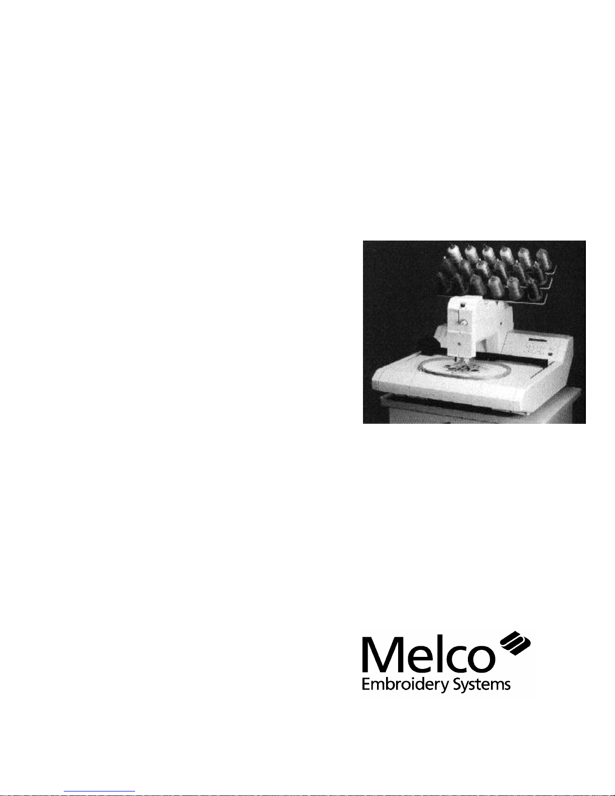
Operation Manual for
the Advantage 18
embroidery peripheral
Part Number 110265-01, Revision A
• 18 Colors
• One Needle
• Automatic Color Change
• Automatic Rethreading
• Under Thread Control
A Saurer Group Company
Page 2

1575 West 124th Avenue
Denver, Colorado 80234
United States of America
E-mail via Internet: publications@melco.com
Copyright © Melco Embroidery Systems, 1995.
ALL RIGHTS RESERVED No part of this publication may be reproduced, stored in a retrieval system, or
transmitted in any form or by any means (electronic, mechanical, photocopying, recording, or
otherwise) without prior written approval of Melco Embroidery Systems. Melco reserves the right to
revise this publication and to make changes in it at any time without obligation of Melco to notify any
person or organization of such revisions or changes.
All precautions have been taken to avoid errors or misrepresentations of facts, equipment, or
products. However, Melco Embroidery Systems does not assume any liability to any party for loss or
damage caused by errors or omissions.
Printed in the United States of America
FIRST DRAFT: November 2, 1995
Page 3

Table of Contents
Advantage 18
Operation Manual
1. Introduction and Installation
Physical Arrangement 1 - 1
The Controller 1 - 2
The Embroidery Head 1 - 2
The Thread Tree 1 - 2
The Keyboard 1 - 2
The Pantograph 1 - 2
Installation 1 - 3
Power Requirements 1 - 3
Static Electricity 1 - 3
Inspecting Your Embroidery Peripheral 1 - 3
Unpacking the Advantage 18 1 - 3
Tables And Cabinets 1 - 3
Embroidery Peripheral 1 - 3
The Air Compressor 1 - 6
Canned Compressed Air 1 - 6
Configuring The Advantage 18 1 - 6
What to Configure 1 - 6
The Peripheral Program 1 - 7
The Unit Number 1 - 7
The Language 1 - 7
How to Configure 1 - 7
Start-Up Messages 1 - 8
2. Operating the Advantage 18
How Threads Are Spliced 2 - 1
Threading the Advantage 18 2 - 1
Threading to the Selector Carriage 2 - 1
Inserting the Thread into the Splicing Cell 2 - 3
Rethreading After a Failure 2 - 3
Thread Types and Needles 2 - 5
Thread Types 2 - 5
Needles 2 - 5
Tensions 2 - 5
The Upper Tension 2 - 5
Bobbin Tension 2 - 5
Installing a Needle 2 - 6
Hooping 2 - 7
Hooping Flat Goods 2 - 7
Loading The Hoop 2 - 8
Cap Frames 2 - 9
Installing the Cap Frame Drive 2 - 9
Cap Hooping 2 - 11
Using a Raised Needle Plate 2 - 11
i
Page 4

Table of Contents
Operation Manual
Advantage 18
Keyboard Operation 2 - 12
3. The Setup Menus
An Overview of the Advantage 18 Menus 3 - 1
Design Menu 3 - 2
Color Menu 3 - 3
Tension Menu 3 - 5
Orientation Menu 3 - 6
Run Design Menu 3 - 7
The Idle Menus 3 - 7
Introduction 2 - 12
The Keys and Their Functions 2 - 12
Key Combinations 2 - 13
Sending a Design 2 - 14
Receiving a Design 2 - 14
Selecting a Design 3 - 2
Deleting a Design 3 - 2
An Example 3 - 4
Change Now 3 - 4
Select the Thread Position 3 - 6
Select the Tension Setting 3 - 6
Setting Orientation 3 - 6
4. The Customizing Menus
Frame Menu 4 - 1
The Frame Idle Display 4 - 2
Return To Origin 4 - 2
Trace Menu 4 - 3
Home Menu 4 - 4
Set Home 4 - 4
Hoop Limits 4 - 4
Power Fail Rescue 4 - 5
Move Menu 4 - 6
When to Use The Move Menu 4 - 6
Trim Menu 4 - 8
Setting the Options 4 - 8
Trim Immediate 4 - 8
Jump Count 4 - 8
Bobbin Menu 4 - 9
The Splicing Menu 4 - 9
Change Thread 4 - 10
Insert Thread 4 - 10
Valve 1 Off 4 - 11
Up Trim Mtr On 4 - 11
Trim Thread 4 - 12
Draw Motor 4 - 12
Low Pressure On 4 - 13
ii
Page 5

Table of Contents
Advantage 18
Operation Manual
High Pressure On 4 - 13
Reset Menu 4 - 14
System Reset 4 - 14
Hard Reset 4 - 14
5. Operator Maintenance
Cleaning the Advantage 18 5 - 1
Cleaning Your Machine’s Exterior Surfaces 5 - 1
Cleaning the Rotary Hook Area 5 - 1
Lubricating the Advantage 18 5 - 2
Lubricating The Embroidery Head 5 - 2
Rotary Hook 5 - 2
Needle Bar 5 - 3
Needle Bar Driver 5 - 4
Upper Connecting Rod 5 - 4
Lower Connecting Rod 5 - 5
Lubricating The Beam 5 - 6
Lubricating the Pulley Assembly 5 - 7
Lubricating the X-Carriage Rollers 5 - 9
Lubricating the Y-Rails 5 - 10
Lubricating the Lower Trimmers 5 - 11
The Rear Trimmer Parts 5 - 12
The Front Trimmer Parts 5 - 12
Embroidery Head Timing 5 - 13
Machine Out Of Timing 5 - 13
Making A Stitch 5 - 14
Setting Timing 5 - 15
Needle Depth Check/Adjustment 5 - 15
Hook Timing 5 - 17
Checking Hook Timing 5 - 18
Adjusting Hook Timing 5 - 19
Cleaning the Color Change Area 5 - 21
Color Change Cover Removal 5 - 21
The Manifold 5 - 22
Upper Trimmers 5 - 23
Pretensioner 5 - 24
Addendums
A. Glossary of Embroidery Terms
B. Error Messages
C. Hoop Sizes
D. The Quick Reference Guide
INDEX
iii
Page 6

Table of Contents
Operation Manual
Advantage 18
iv
Page 7
1 - 1
110265-01, Rev. A 1. Introduction and Installation
1. Introduction and Installation
The Advantage 18 is an 18 color embroidery peripheral using an innovative, air driven, color
change process that automatically rethreads its single needle. You may embroider a design with up
to 18 colors without pausing to change spools or manually rethread the needle. In addition to
embroidering on flat goods, the Advantage 18 embroiders on caps using the optional cap frame
attachment.
WARNING! For operator safety, Never allow untrained
personnel operate the Advantage 18.
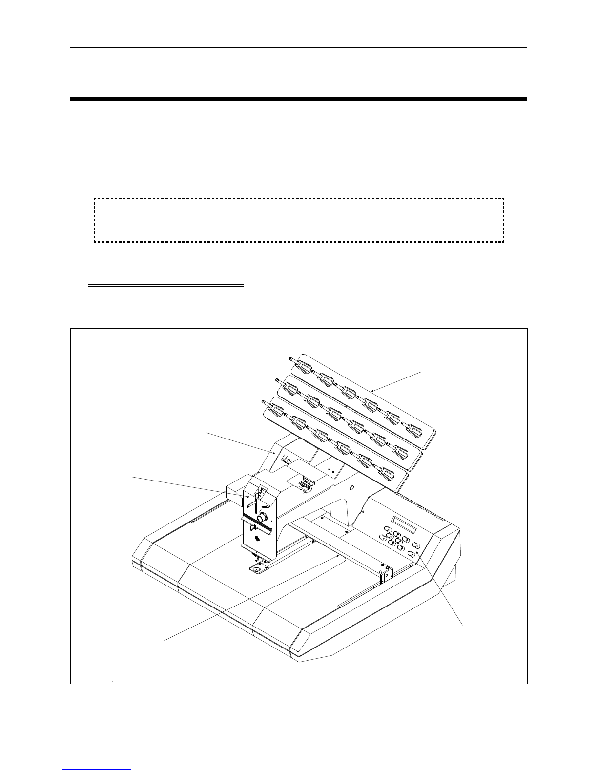
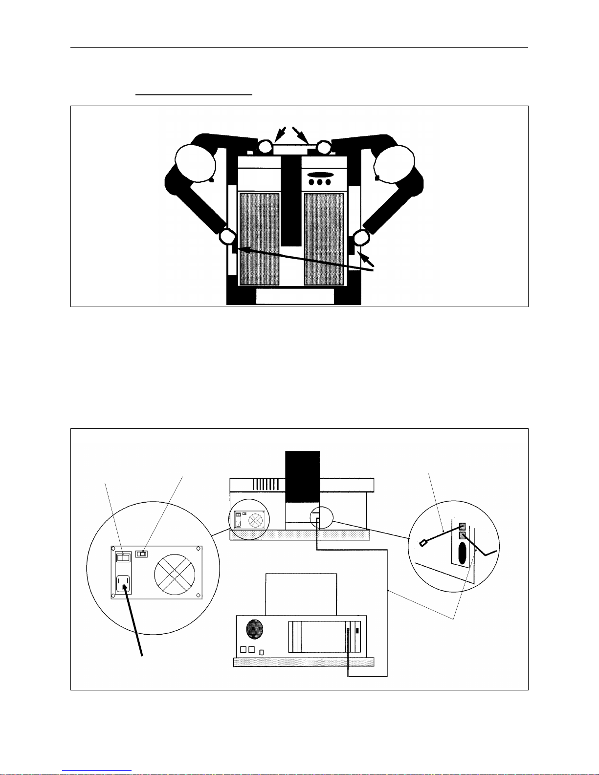
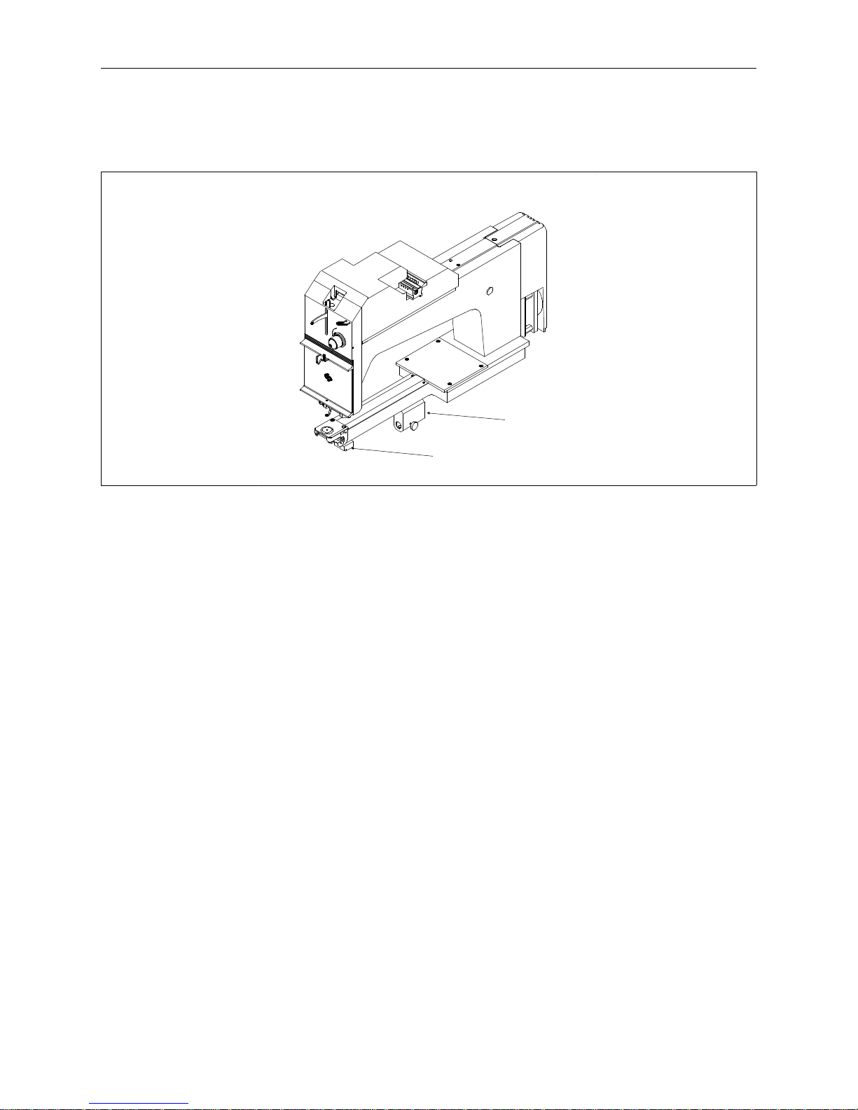
Physical Arrangement
The Advantage 18 has five sections: the controller, the embroidery head, the thread tree, the
keyboard, and the pantograph (see Figure 1-1).
Embroidery
Head
Pantograph
Thread Tree
Controller
Keyboard
Figure 1-1
Page 8
1 - 2 Physical Arrangement
Advantage 18 Operation Manual Melco Embroidery Systems
The Controller
The controller contains the printed circuit boards (PCB’s) and electronics that control much of the
machine’s operation.
The Embroidery Head
The embroidery head consists of the parts that move the needle, advance the thread, and produce
stitches.
The Thread Tree
The thread tree holds up to 18 spools of thread and mounts on the embroidery head. Its
connecting plastic tubes feed the individual threads from the spools to the thread select carriage.
The Keyboard
Commands are given to the peripheral through the keyboard. The Liquid Crystal Display (LCD)
displays informative messages. The main power supply and the motor that moves the pantograph
forward and backward are located under the keyboard cover.
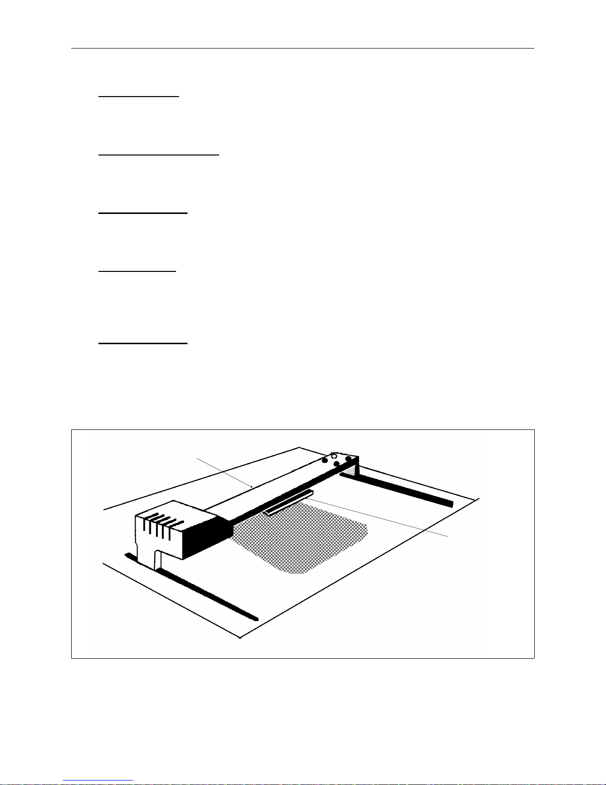
The Pantograph
The pantograph (see Figure 1-2) moves the hoop right or left (the X axis) and forward or backward
(the Y axis). The beam is the arm of the pantograph that moves forward or backward. Inside the
beam is the X-carriage that moves left or right. The hooped garment attaches to the X-carriage. As
the X-carriage moves the hoop left or right, the beam moves the X-carriage forward or backward.
This movement controls the placement of the stitching.
Beam
X-Carriage
and Hoop
Attachment
Figure 1-2
Page 9
Unpacking the Advantage 18 1 - 3
110265-01, Rev. A 1. Introduction and Installation
Installation
This section explains how to get your Advantage 18 unpacked, powered up, and connected to your
computer. Directions for installing software are in the software operation manuals.
If you are using the Advantage 18’s optional disk drive, skip the directions for connecting the
Advantage 18 to a computer. All instructions for the optional disk drive are in its operation manual.
Power Requirements
Electricity can have power spikes or surges that may affect your computer or embroidery
peripheral’s operation. Melco suggests a dedicated power for your system with a line conditioner.
Inspecting Your Embroidery Peripheral
Inspect all cartons for physical damage. If any damage is found, contact the shipper.
Unpacking the Advantage 18
When cutting open the boxes be careful not to damage any of the equipment. Continue to inspect
the parts for any physical damage not apparent from the condition of the cartons. Again, contact
the shipper to report any damage.
Tables And Cabinets
Unpack and place the work station furniture before unpacking the embroidery equipment.
Embroidery Peripheral
1. Carefully cut and remove the binding straps from the cardboard shipping carton containing the
embroidery peripheral.
Foam Cushions
2. Lift the top cover off the outside
carton.
3. Remove the outside carton from
Embroidery
Head
the bottom cover.
4. Remove any packing boxes and
protective pads from around the
embroidery head (see Figure 1-3).
CAUTION: Use two
Packing Boxes
people to remove and
place the embroidery
peripheral.
Figure 1-3
Page 10
1 - 4 Installation
Advantage 18 Operation Manual Melco Embroidery Systems
5. Grasp the underside of the machine at the four locations indicated in Figure 1-4.
Lift Here
Lift Here
Figure 1-5
6. Keep the embroidery peripheral level. The unit and foam packaging should come out of the
carton with relative ease.
7. Place the embroidery peripheral onto its dedicated work station.
8. Set the 115V/220V selector switch to the proper setting for your power supply. The switch is
just to the right of the ON/OFF switch (see Figure 1-5).
Machine
ON/OFF
Switch
Voltage
Selector
Switch
Rear of Peripheral
Terminator
Cable
Attach Power
Cable here
Network
Cable
Rear of Computer
Figure 1-4
Page 11

Canned Compressed Air 1 - 5
110265-01, Rev. A 1. Introduction and Installation
9. Attach the power cable to the rear of the unit as shown in Figure 1-5.
10. Still referring to Figure 1-5, install the network cable between the computer and the Advantage
18. If you only have one peripheral device attached to the computer, install the terminator
cable to the machine as the figure shows. If more than one peripheral device is attached to the
computer, install the terminator cable on the last peripheral in the series.
11. Install the power cords of the computer, the monitor, and the embroidery peripheral to the
power source.
The Air Compressor
You must provide an air compressor for attaching the Advantage 18. The air compressor must meet
the following requirements:
• Air pressure of 100 to 120 psi (pounds per square inch)
• Air flow of 2 scfm (standard cubic feet per minute) at 90 psi for each Advantage 18
• A regulator with a minimum range of 70 to 100 psi
• A 5 micron particle filter
• A 0.5 micron oil-coalescing filter
The Advantage 18 comes with a 6 foot long air supply line with a standard quick-disconnect fitting.
To install the tubing on the Advantage 18:
1. Route the free end of the tubing through the open base of the thread tree.
2. Insert the end of the tubing into the air supply fitting with a red ring around it. It is located just
in front of the thread tree, at the back of the color change assembly.
3. Push the tubing into the fitting as far as it will go.
Canned Compressed Air
Use a can of compressed air that is free from contaminants to insert threads through the thread
guide tubes.
Configuring The Advantage 18
When turning on the Advantage 18 for the first time it must be configured to operate properly.
After configuration is completed, each time the Advantage 18 is turned on it checks its memory for
the needed data. The peripheral requires reconfiguration when a new PCB is installed.
Page 12

1 - 6 Configuring The Advantage 18
Advantage 18 Operation Manual Melco Embroidery Systems
What to Configure
The three items of information set during configuration are:
• Peripheral Program
• Unit Number
• Language
The Peripheral Program
The CPU used in the Advantage 18 is also used in other Melco peripherals. The peripheral program
is set to match the CPU to the peripheral it is controlling. On new units the peripheral program is
set at the factory. However, if you replace the CPU board, you must reset the peripheral program.
the Advantage 18 is configured with the incorrect peripheral program, it will not operate properly,
and may be damaged.
The Unit Number
A network address or unit number for each peripheral attached to an EDS system must also be set
at the peripheral. The number may be between 1 and 16 when using EDS II software or between 1
and 64 when using other Melco software. Each peripheral must have a unique unit number.
If
Before sending designs to the Advantage 18, enable the unit number on the computer. See your
software operation manual for instructions.
The Language
Set the language displayed by the LCD to either English or Spanish.
How to Configure
Access the configuration mode by
following these steps:
1. Before you turn on the Advantage 18,
Keyboard
locate the keyboard in the upper right
area of the peripheral as shown in
Figure 1-6.
2. Locate the power switch at the rear of
the unit. It is a rocker switch above
the power cord as shown in Figure
1-5.
3. Press and hold [ALT], [
⇑], and [⇓] while
turning the power ON.
Figure 1-6
Page 13

How to Configure 1 - 7
110265-01, Rev. A 1. Introduction and Installation
4. Continue to press these keys until the unit ‘‘beeps’’ and the display shows a message that says
ADV-18 (or some other peripheral identification code). Release the three keys.
5. If the LCD displays anything other than ADV-18, press [
⇑] or [⇓] until it displays: ADV-18.
6. Press [ENTER] to set the peripheral program.
7. Press [
⇑] or [⇓] and the LCD will display: UNIT NUMBER 01. Keep pressing the arrow key until the
number you want displays. You cannot have two peripherals with the same unit number
attached to the same computer.
8. Press [ENTER] to set the unit number.
9. The last item you select is the display language. Press [
⇑] or [⇓] to display English or Spanish and
press [ENTER] to select that language.
Start-Up Messages
Once configured, a series of messages will display during power up. Usually the messages are
simply informational, but sometimes they will require a keyboard entry from the operator. The
messages displayed will depend on the combination of the computer and peripheral operating
modes.
When there is a completed link to the computer the series of messages are:
DSKBIOS Version# Bytes of free memory
DNLOAD REQUESTED
POWER UP. . .
ADV-18 Version#
If a link to the computer is not make because it is not on or it is busy, the following messages will
flash alternately until the Advantage 18 can link:
DSKBIOS version # bytes of free memory
UNIT #
If the Advantage 18 finds a problem in its self-check, it will display the appropriate error message
and wait for a response.
Appendix B contains a complete listing of the error messages.
Page 14

1 - 8 Start-Up Messages
Advantage 18 Operation Manual Melco Embroidery Systems
Page 15
Threading to the Selector Carriage 2 - 1
110265-01, Rev. A 2. Operating the Advantage 18
2. Operating the Advantage 18
How Threads Are Spliced
During a color change, both the current and new threads enter into the thread splicing cell. Inside
the splicing cell a short, forceful burst of air fluffs out the fibers of both threads causing them to
intertwine, making a secure slice between them. The old thread is then pulled through the needle,
followed by the splice and the new thread. The new thread is trimmed after passing through the
needle, and the old thread and splice are directed into a holding bin for later disposal. This
patented process allows the Advantage 18 to perform color changes and rethreading automatically
while using a single needle and tensioner.
Threading the Advantage 18
Although the Advantage 18 will automatically rethread when it performs a color change, you may
need to perform manual threading when the following occurs:
• Initial set-up
• Using short-fiber threads that do not splice well
• A thread break
• Mechanical failures
Follow these directions to thread the machine:
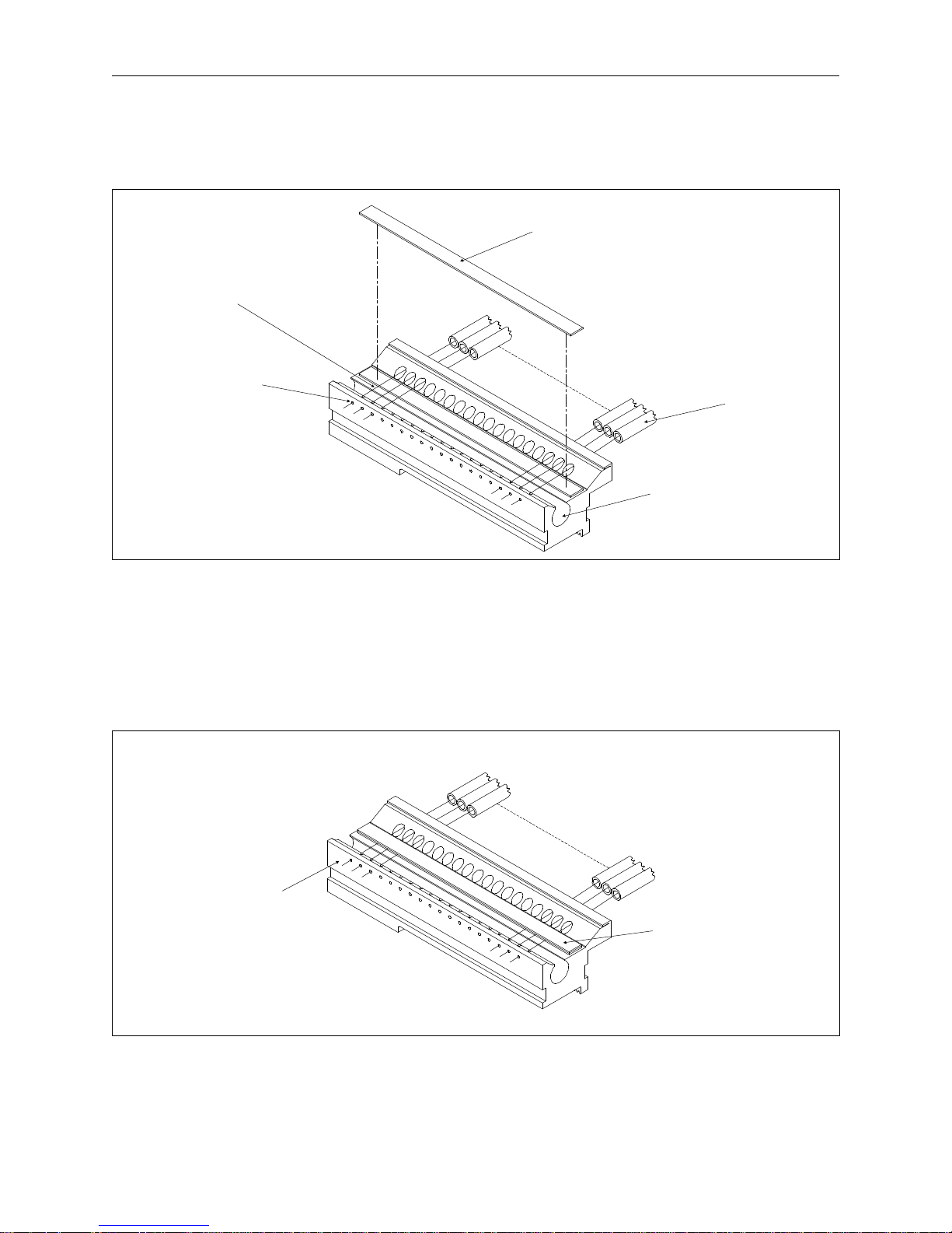
Threading to the Selector Carriage
1. Put a spool of thread on position number 1 of the thread tree.
2. Insert an inch or two of thread into the center of the thread guide tube.
3. Use a can of compressed air to direct a short burst of air into the tube as shown in Figure 2-1.
The compressed air will force the thread through the tubing to the thread selector carriage.
Thread Guide Tube
Compressed Air
Thread Spool
Figure 2-1
Page 16
2 - 2 Threading the Advantage 18
Advantage 18 Operation Manual Melco Embroidery Systems
4. Lift the pretensioner magnet. Position the thread in the groove, over the idler roller, and through
the guide hole as shown in Figures 2-2 and 2-3.
Pretensioner Magnet
(lifted for thread placement)
Groove
Guide Hole
Idler Roller
Figure 2-2
5. Repeat steps 1 through 4 for all the thread positions.
6. Replace the pretensioner.
7. Trim the ends of the thread to 1/8 inch in front of the carriage (see Figure 2-3).
Thread tubes
from the
thread tree
Threads trimmed
to 1/8 inch.
Pretensioner Magnet
(in operating position)
Figure 2-3
Page 17

Rethreading After a Failure 2 - 3
110265-01, Rev. A 2. Operating the Advantage 18
Inserting the Thread into the Splicing Cell
1. Move the selector carriage to the desired thread position by pressing [ALT][
space to the left or [ALT][
⇒] to move one space to the right.
⇐] to move one
2. Press [ALT][ENTER] to display one of three idle menus. Press [ENTER] to toggle through these
menus until reaching one that displays: THD: 1* TENSION: 27. The number with the asterisk
beside it is the current thread position of the selector carriage. A complete description of the
Idle menus is in the next chapter.
3. Press [ALT][
⇑] to move the selector carriage to thread position 18 or press [ALT][⇓] to move the
selector carriage to thread position 1.
4. To move the selector carriage to the previously selected thread and insert it through the splicing
cell, press the [FAST/SLOW] key. The
it is the
first key pressed after moving the selector carriage with one of the [ALT][arrow key]
only time [FAST/SLOW] will perform this function is when
combinations.
NOTE: By allowing the selector carriage to move off the selected thread position and then travel
back to it before performing an insert, the tails of the neighboring threads become
positioned to avoid interference. Using [ALT][
⇑] or [ALT][⇓] stores the previous thread
position so the selector carriage knows where to return. Press [FAST/SLOW] immediately
after accessing [ALT]
[⇐] or [ALT][⇒] to perform an insert at that position.
OR
Access the insert thread option in the Splicing Menu. This is discussed in the Splicing Menu section
later in this chapter.
5. Finish threading the machine using Figure 2-4 as a guide.
Rethreading After a Failure
If a thread fails to insert through the splicing cell, perform these recovery steps before trying the
insert again.
1. Press [ALT][
⇑] or [ALT][⇓] to move the selector carriage all the way to the left or right depending
on which gives you the best access to the thread position.
2. If the tail of the thread is free, trim it back to 1/8 inch.
OR
If the tail of the thread has become tangled under the color change cover, be sure to clear the
entire thread path. You may have to remove the color change cover to do this.
3. Trim the thread to 1/8 inch.
4. Press [FAST/SLOW]. The selector carriage will move back to the previous thread and perform an
insert.
Page 18
2 - 4 Threading the Advantage 18
Advantage 18 Operation Manual Melco Embroidery Systems
The Advantage 18 Thread Path
Figure 2-4
NOTE: The thread is passed
between the disks of the
tensioner only once.
Page 19

Bobbin Tension 2 - 5
110265-01, Rev. A 2. Operating the Advantage 18
Thread Types and Needles
Thread Types
The Advantage 18 can perform automatic color changes between a variety of thread types.
However, the longer the thread fibers, the better the splice. Because synthetic threads have longer
fibers than natural threads such as cotton, a synthetic to synthetic splice is the most consistent. The
following table lists general guidelines for the splicing quality of different thread types. Of course,
the two threads in a splice can be different types of thread. Even if a thread does not splice well,
you may embroider with it on the Advantage 18 by threading it manually.
Synthetic Best for splicing
Blends of Synthetic and Natural Better than all natural
Natural May need manual rethreading
Monofilaments Must be manually threaded
Metalics Must be manually threaded
Needles
During an Advantage 18 color change, the actual splice of the two threads passes through the eye
of the needle. For the splice to easily pass through the eye, use a standard 80/12 size needle or
larger.
Tensions
Excellent embroidery quality is achieved when both the upper thread and bobbin thread tensions
are set properly. Experience and practice allows customized tension settings based on factors such
as: threads, material, backing, needle type, stitch size, and hooping.
The Upper Tension
There is one upper tensioner on the Advantage 18 used by all 18 thread positions. Because
different types and weights of threads require different tensions, the Advantage 18 tensioner is
designed to store the tension setting for each thread position in memory.
When a tension is reset, the new setting replaces the old one in memory for that thread position.
Keeping the same types and weights of threads in the same thread positions will reduce the
number of tension adjustments.
Bobbin Tension
The same factors affecting upper tensions affect bobbin tension. The bobbin tension is adjusted
manually, however, by rotating a set screw on the bobbin case (see Figure 2-5).
Page 20
2 - 6 Installing a Needle
Advantage 18 Operation Manual Melco Embroidery Systems
Bobbin Case
Spring
Set
Screw
Slit
Thread
Side View End View
Bobbin Case
Bobbin
Spool
Pigtail
Note the direction that the thread is wound on the
bobbin spool for insertion into the bobbin case.
Figure 2-5
1 Put the bobbin spool into the bobbin case as illustrated in Figure 2-5. When looking at the open
end of the bobbin case, the thread should rotate clockwise off the bobbin spool when you pull
on the thread.
2. Pass the thread through the slit in the bobbin case and under the spring.
3. Using a small, flat-blade screw driver, turn the set screw until you feel a slight resistance when
the thread is pulled from the bobbin. Set the tension so that when you hold the bobbin case
suspended by its thread:
• No thread feeds out when you are not moving it
• About an inch of thread feeds out when you jiggle it slightly
4. With the bobbin tension adjusted, pass the bobbin thread through the bobbin case pig tail.
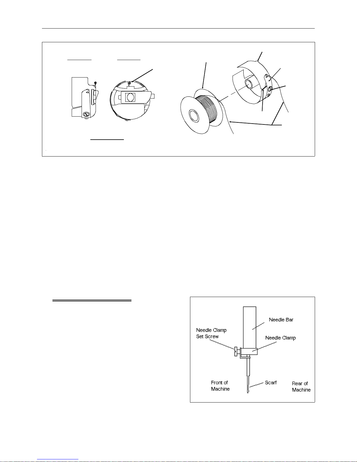
Installing a Needle
The needle clamp set screw holds the needle in place
as shown in Figure 2-6. Using the small, flat-blade
screw driver from the operator’s tool kit:
1. Turn the set screw counterclockwise until the
needle can slide down and out of the needle bar.
2. With the scarf of the new needle toward the rear
of the embroidery head, slide the needle into the
needle bar as far as it will go and tighten the set
screw.
Figure 2-6
Page 21
Hooping Flat Goods 2 - 7
110265-01, Rev. A 2. Operating the Advantage 18
Hooping
A properly hooped garment is one without any folds caught in the hoop and is as taut as possible
without permanently stretching the fabric, especially knits, jerseys, and other loosely woven fabrics.
Hooping Flat Goods
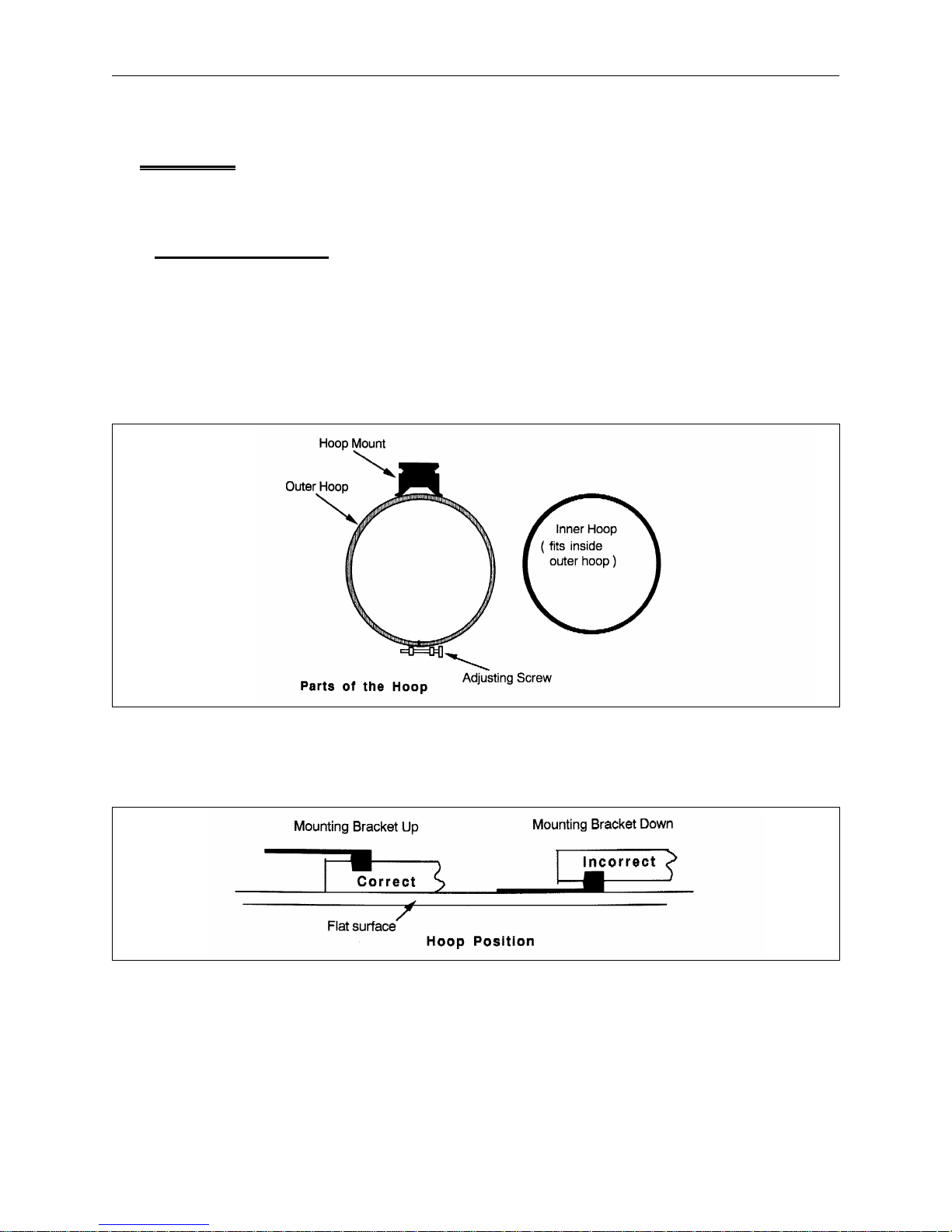
Follow these steps for hooping material in a circular or oval hoop on the table top insert.
1. Select a hoop that allows the complete design to fit with a comfortable margin of blank fabric
around the inside edge. Later you will learn how to use the Trace menu to make sure you have
the right size hoop.
2. Loosen the adjusting screw on the outer hoop by turning it counterclockwise (see Figure 2-7).
Figure 2-7
3. Place the outer hoop on a clean, flat surface with the mounting bracket on the side that is up
and away from the flat surface (see Figure 2-8).
Figure 2-8
4. On top of the outer hoop, place enough backing material to cover it.
5. Place your material on top of the backing.
Page 22
2 - 8 Hooping
Advantage 18 Operation Manual Melco Embroidery Systems
6. Press the inner hoop into the outer hoop with the fabric and backing between them as shown in
Figure 2-9. Pull the outside edges of the material inward, toward the center of the hoop. This
tightens the material inside the hoop without popping the hoop apart.
Figure 2-9
7. When the material is hooped properly, tighten the outer hoop adjusting screw. Tightening this
screw will
permanent imprint in your material.
not tighten the fabric, it simply secures it. Tightening it too much can leave a
Loading The Hoop
To attach the hoop to the carriage:
1. Place the left notch of the hoop mounting bracket against the carriage stub as shown in Figure
2-10.
X-Carriage
Thumb Lever
Hoop Mounting
Bracket
Figure 2-10
Page 23
Cap Frames 2 - 9
110265-01, Rev. A 2. Operating the Advantage 18
2. Press the thumb lever towards the rear of the carriage.
3. Push the hoop bracket up to the lever stub and release the lever, snapping the lever stub into
the right carriage notch.
Cap Frames
Because a cap is not flat it cannot be hooped in a flat hoop. To solve this problem, a special device
called a cap frame is used. The cap frame option consists of two parts: 1) The cap frame that holds
the cap and attaches to the cap frame drive; and 2) The cap frame drive that secures to the X
carriage and the front of the machine.
Installing the Cap Frame Drive
Attach the cap frame drive by following these steps and referring to Figure 2-11.
CAUTION! To avoid possible cap frame drive or other machine damage, Set
Home before installing the cap frame drive.
Cap Frame Drive
SIDE VIEW
Cap Frame Drive Shaft
Dove-Tail Bracket
Figure 2-11
FRONT VIEW
Thumb Screw
Hoop
Bracket
1. Remove the table top insert from the embroidery area. This allows access to the cap frame
mounting brackets under the bed of the embroidery head.
2. Center the pantograph in both X and Y directions using the arrow keys.
Page 24
2 - 10 Hooping
Advantage 18 Operation Manual Melco Embroidery Systems
3. Under the cylinder arm, locate the dove-tail mount under the needle area and a bracket with a
round hole at the rear of the embroidery head (see Figure 2-12).
Rear Mounting Bracket
Dove-Tail Mount
Figure 2-12
4. Loosen the thumb screw on the rear bracket.
5. Loosen the thumb screw on the cap frame drive dove tail bracket.
6. The cap frame drive has a hoop bracket on top of it. Pulling the cap frame drive shaft towards
you, attach the hoop bracket to the X carriage. It attaches just like a regular hoop.
7. Guide the cap frame drive shaft into the hole in the rear mounting bracket. At the same time,
insert the cap frame drive dove-tail bracket into the dove-tail mount.
8. Push the cap frame drive shaft into the bracket hole as far as it will go.
9. Tighten the thumb screw on the rear bracket.
10. Tighten the thumb screw on the dove-tail bracket.
Page 25
Cap Frames 2 - 11
110265-01, Rev. A 2. Operating the Advantage 18
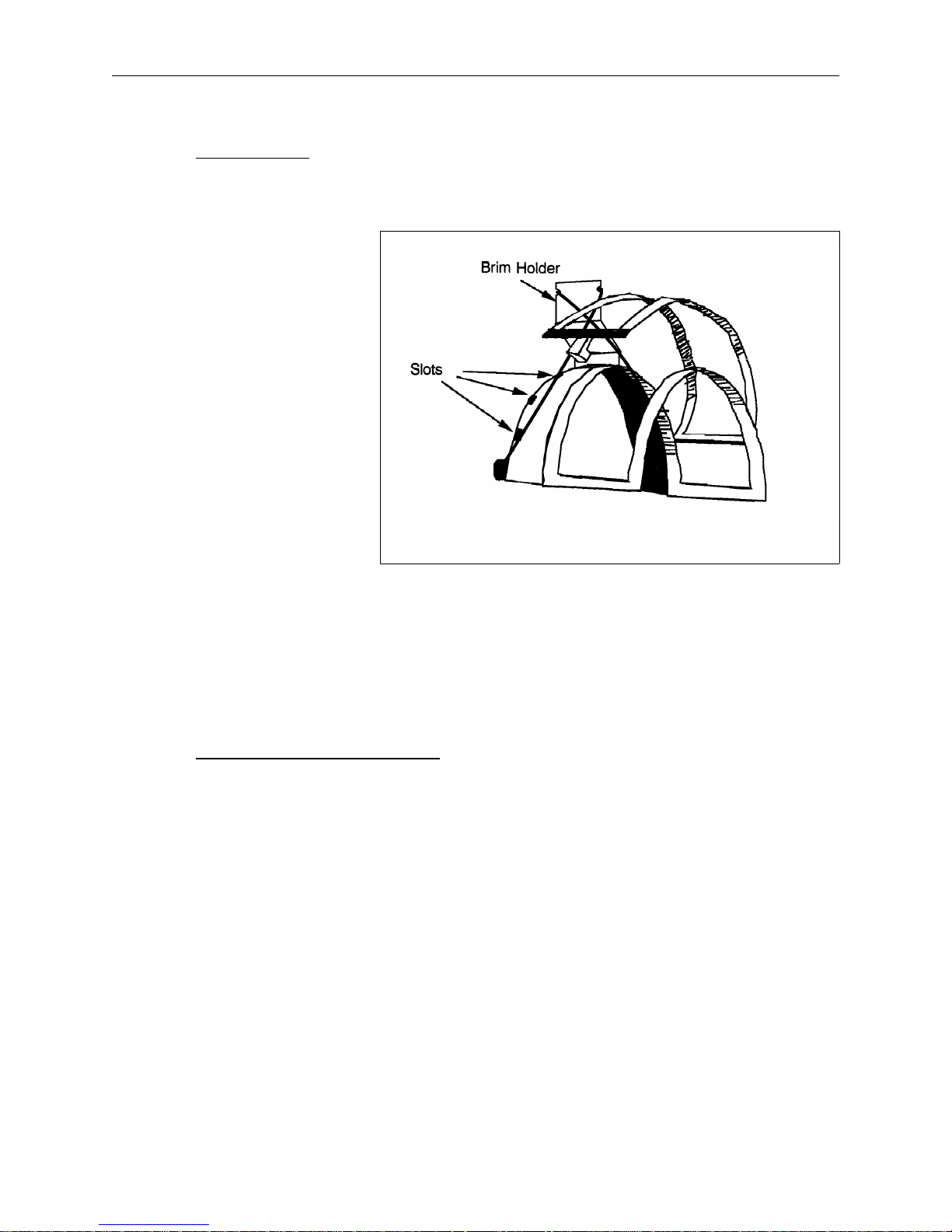
Cap Hooping
The following steps and Figure 2-13 explain how to put a cap in the cap frame.
1. Open the cap frame cover. The
latch should be on the left side
of the cap frame.
2. If you are using backing, place it
inside the cap.
3. Slide the top of your cap around
the body of the cap frame.
Keep the sides of the cap inside
the outer edges of the cap
frame. Push the cap completely
onto the cap frame.
4. Close the cap frame cover while
keeping the cap as straight,
fold-free, and taut as possible.
5. Secure the cap’s brim within the
brim holder mechanism.
Cap Frame
Figure 2-13
6. Install the cap frame onto the cap frame drive by:
• Aligning the cap frame and cap frame drive.
• Snapping the cap frame slots under the roller clamps on the cap frame drive.
Using a Raised Needle Plate
When the cap frame is attached, the curve of the frame leaves extra space between the needle
plate and the cap. This sometimes creates poor embroidery quality. Cap embroidery may be
improved by installing the raised needle plate option to reduce this extra space.
When embroidering with the raised needle plate, place extra spacers around the needle bar in the
needle case. The spacers raise the presser foot to compensate for the height of the raised needle
plate.
When returning to flat goods, install the normal needle plate and remove the extra spacers from
around the needle bars.
The raised needle plate option comes with its own installation procedures. Refer to those
procedures for proper installation and use.
Page 26
2 - 12 Keyboard Operation
Advantage 18 Operation Manual Melco Embroidery Systems
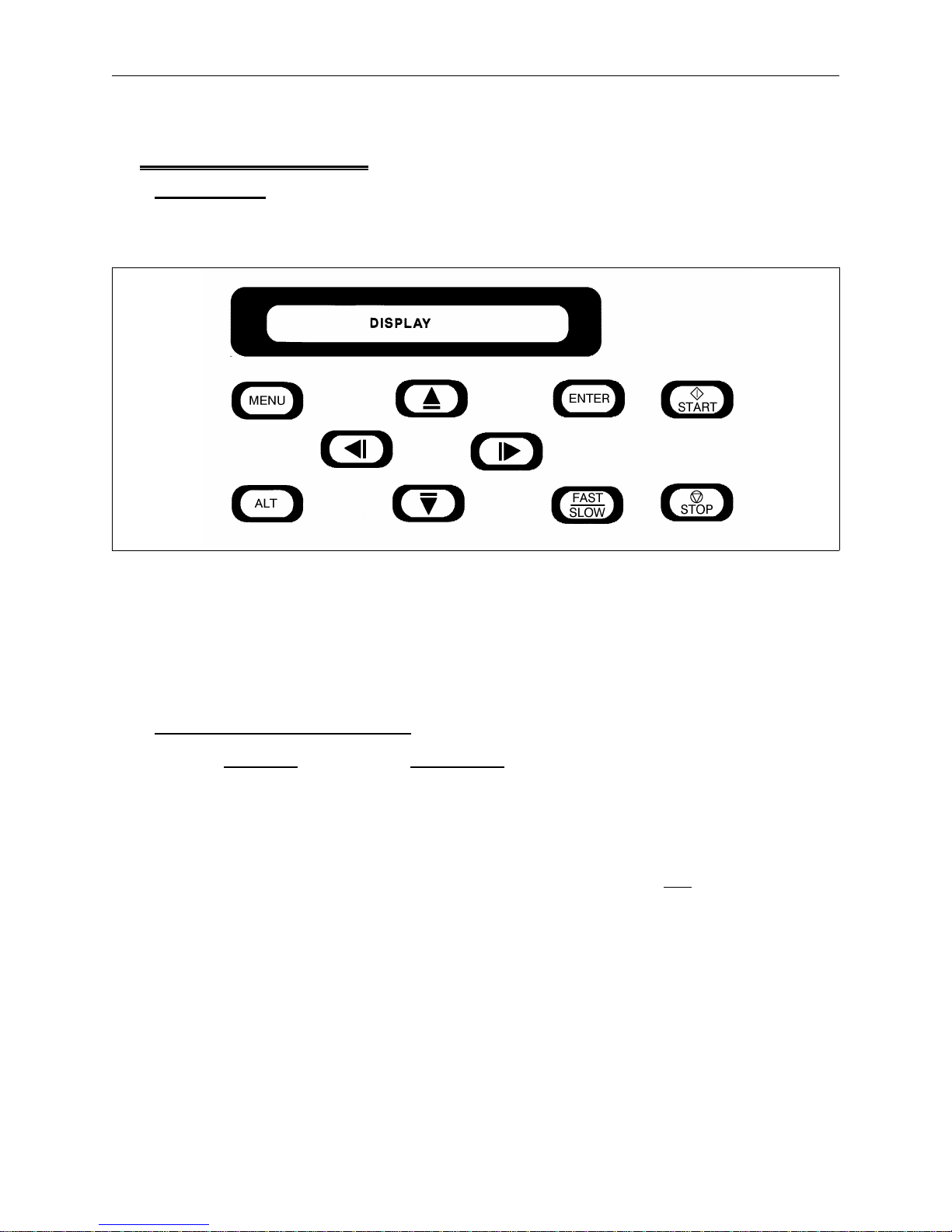
Keyboard Operation
Introduction
After receiving a design, the Advantage 18 uses its own program to start and direct the embroidery
process. The Advantage 18 operation is controlled through the keyboard illustrated in Figure 2-14.
Figure 2-14
The keyboard has ten keys and a display window called a Liquid Crystal Display (LCD). The LCD
displays menu options and messages. The keys allow you to move between menus, enter
commands, and select various other settings. Following is a description of the keys and their
functions in the main menus and the idle menus.
The Keys and Their Functions
Key Name Key Function
[MENU] Moves from one menu to the next. After the last menu
displays, it wraps back to the first menu.
[ALT] Never used alone. Held down while pressing another key,
allows the other key to take on an
ALTernate function.
See Key Combinations.
[ENTER] Makes a selection similar to clicking on the OK button in
Windows or pressing the [ENTER] key on your computer
keyboard. Also scrolls through the idle menus.
[FAST/SLOW] Toggles the hoop carriage speed fast or slow. Also inserts
a thread through the splicing cell when used immediately
after an [ALT][ARROW] key combination.
Page 27

The Keys and Their Functions 2 - 13
110265-01, Rev. A 2. Operating the Advantage 18
[⇒] or [RIGHT ARROW] Moves the needle position to the right in the embroidery
field (hoop moves left). Also used to select values for sub
menu options.
[
⇐] or [LEFT ARROW] Moves the needle position to the left in the embroidery
field (hoop moves to the right). Also used to select values
for sub menu options.
[
⇑] or [UP ARROW] Moves the needle position back in the embroidery field
and scrolls up a menu list. Also used to change sub menu
values.
[
⇓] or [DOWN ARROW] Moves the needle position down in the embroidery field
and scrolls down a menu list. Also used to change sub
menu values.
START Starts embroidering. Also starts the TRACING function.
STOP Stops any job. Also used to "frame forward" or
"frame backward" in idle or in the FRAME menu.
Key Combinations
Keys Combination Functions
[ALT][MENU] Displays the
previous menu.
[ALT][ENTER] Exits sub menu and displays one of three idle menus even
while the machine is embroidering.
[ALT][
⇐] Moves the selector carriage one thread position to the left
when the machine is in idle. Decreases upper thread
tension while the machine is embroidering.
[ALT][
⇒] Moves the selector carriage one thread position to the right
when the machine is in idle. Increases the upper thread
tension while the machine is embroidering.
[ALT][
⇑] Increases the maximum embroidery speed in increments
of 50 spm (stitches per minute) when the machine is
embroidering. The maximum is 900 spm for flat goods
embroidery and 800 spm for the cap frame. Also moves
the selector carriage to thread position 18 when the
machine is in idle.
[ALT][
⇓] Decreases the embroidery speed in increments of 50 spm
when the machine is embroidering. The minimum is 400
spm. Also moves the selector carriage to thread position 1
when the machine is idle.
Page 28

2 - 14 Keyboard Operation
Advantage 18 Operation Manual Melco Embroidery Systems
Sending a Design
The Advantage 18 operates with either EDS II or EDS III software. In your EDS system prepare and
save an EXP design. The following steps are individualized instructions for EDS II and EDS III users.
Complete
For EDS II:
1. Press F10: Peripherals in the main menu.
2. From the peripherals menu, press: F2: Send Design.
3. Type the file name of the design, a space, and the Advantage 18 unit number.
4. Press the Enter key.
For example, to send the design "SHIP" to peripheral #1, type:
only the instructions that apply to your system.
SHIP 1
For EDS III:
1. Click on Peripherals in the application or layout window and a drop-down menu displays.
2. Click on Transfer and a dialog box displays.
3. Select the appropriate information.
4. Click on OK.
More information is available in the EDS II and EDS III operation manuals. Consult the sections
concerning sending designs from the computer to the peripheral.
Receiving a Design
Now access the design in the Advantage 18’s design buffer. Remember the SHIP design is just an
example. Your file name and statistics may differ.
1. At the Advantage 18 keyboard, press [MENU] until the display reads:
DESIGN MENU
2. Press [ENTER]. The display now reads:
SHIP 1380
SHIP is the design name. 1380 is the size of the design in bytes.
3. If you had more than one design in the buffer, pressing [
⇑] or [⇓] scrolls through the list.
Page 29

3 - 1
110265-01, Rev. A 3. The Setup Menus
3. The Setup Menus
Find all the Advantage 18 menus listed below with a brief description of their functions. Detailed
explanations of the Design, Color, Tension, Orientation and Run menus follow the brief overview.
These are "The Setup Menus" used for every design. Except for the Head Timing menu, the
remaining menus are discussed in Chapter 4, "The Customization Menus." Discussion of the Head
Timing menu is in Chapter 5, "Maintenance."
An Overview of the Advantage 18 Menus
DESIGN MENU
Lists all the designs in the Advantage 18 design buffer, in the order sent. Select a design for
embroidery or to delete a design from the buffer.
COLOR MENU
Sets the color sequence.
TENSION MENU
Sets and remembers the upper tension for each thread position.
ORIENTATION MENU
Positions a design in one of eight combinations for placement in the embroidery field.
RUN DESIGN
Inserts the selected design and color sequence into the run buffer. Also allows the design to
embroider after you Set Home.
FRAME MENU
Sets the direction, either forward or backward, to move through a design to correct embroidery
errors. Allows precise corrections.
TRACE MENU
Traces the outline of a design to verify a design fits in the selected hoop.
HOME MENU
Sets the"HOME POSITION," selects hoop sizes, and provides power fail rescue functions.
MOVE MENU
Moves the needle within the embroidery field.
HEAD TIMING MENU
Enables the operator to set, correct, or adjust the Needle Depth and Hook Timing.
TRIM MENU
Sets the Trimmer Option.
Page 30

3 - 2 Design Menu
Advantage 18 Operation Manual Melco Embroidery Systems
SPLICING MENU
Primarily used for troubleshooting. Provides an option to insert the thread through the splicing cell
or change a thread selection temporarily.
RESET MENU
Clears stitch counts and run buffer without turning off the machine. You do
not delete a job from
this menu. Used to perform a "hard reset" which restores any altered parameters to their default
settings.
Design Menu
When a design is sent from the computer to the Advantage 18, it is stored in the design buffer.
The Design Menu displays the buffer contents and allows you to select a design to embroider or
delete. To access the Design Menu, the Advantage 18 must be powered up but not embroidering
or making a color change.
Selecting a Design
To select a design, follow these steps:
1. Press [MENU] until the LCD displays: DESIGN MENU.
2. Press [ENTER] to display the first design.
3. Scroll through the designs with the [
⇑] key or [⇓] key until you reach the design you want.
4. Press [ENTER] to select the design. The LCD displays the next menu.
Deleting a Design
If you are not using the AutoDelete option on your computer, the design remains in the buffer. To
delete a design from the buffer, follow these steps:
1. Press [MENU] until the LCD displays: DESIGN MENU.
2. Press [ENTER].
3. Use [
4. Press [ALT][
5. Press [
⇑] or [⇓] to scroll to the design you want to delete.
⇓] and the LCD displays: KILL design name?
⇑] for YES, or [⇓] for NO.
6. Press [ENTER] to complete the deletion.
Page 31

Deleting a Design 3 - 3
110265-01, Rev. A 3. The Setup Menus
Color Menu
Scroll through the top level menus, or press [ENTER] from the Design Menu to reach the Color
Menu.
The Advantage 18 can embroider up to 99 colors in a single design. The number of colors used and
the order in which they embroider is called the color sequence. Use the Color Menu to set the color
sequence.
1. Press [MENU] until the LCD displays: COLOR MENU.
2. Press [ENTER] and the display reads
:
COLOR 1:1 (18)
Color Sequence
Thread Position
The color sequence number indicates the current position in the color change order. The 1 in this
position means that it is the first color used in the design, before any color change commands. A
six in this position would mean that this is the sixth color used in the design, and there have been
five color change commands. Acceptable numbers in this position are 1 through 99.
3. Press [
⇒] to move forward or [⇐] to move backward toward the desired color sequence
number. Press and hold to scroll.
The
thread position number refers to the cone number on the thread tree. Acceptable numbers in
this position are 1 through 18, and the special characters:
-- Embroiders using the previous color selection.
Total Color Selections
0 Stops the machine at this color change. Press [Start] to resume embroidering.
P Pauses the machine at each subsequent color change. Press [Start] each time to resume
embroidering.
4. Press [
The
⇑] to increase or [⇓] to decrease the thread position number. Press and hold to scroll.
total color selections number refers to the number of positions in the color sequence. The
number (18) means there are eighteen thread positions individually programmed in the Color Menu.
Acceptable numbers in total color selections are 1 through 99. When the Advantage 18 comes
from the factory, the default number is (18). As you insert or delete color sequences, the total color
selections number increases or decreases respectively.
Page 32

3 - 4 Color Menu
Advantage 18 Operation Manual Melco Embroidery Systems
5. To add to the end of the color sequence, press and hold [⇒] until you reach color sequence 19.
Notice that the total color selections value is still 18.
6. Press [
7. To insert a new color sequence before the current color sequence location, press [ALT][
⇑] or [⇓] to create another color sequence. The total color selections value is now 19.
⇑]. The
total color selections number will increase by one.
8. Press [ALT][
⇓] to delete the current color sequence number. The total color selections number
will decrease by one.
9. When finished setting the Color Menu, press [ENTER] or [MENU].
A hard reset or reconfiguration reset all Color Menu values to their default settings. The default
total color selections is 18.
An Example
Following is an example to demonstrate how to set the Color Menu using two methods:
If you have a design with three flowers, each to be embroidered in green (cone 6), blue (cone 12),
and yellow (cone 5), you could set each individual color selection as shown in the left column. This
results in a total color selections value of 9. In the example on the right, however, only three
selections are made. The total color selections become (3), forcing the color sequence to wrap after
every third color change command. The embroidery result will be identical.
COLOR 1: 6 (9) COLOR 1: 6 (3)
COLOR 2:12 (9) OR COLOR 2:12 (3)
COLOR 3: 5 (9) COLOR 3: 5 (3)
COLOR 4: 6 (9)
COLOR 5:12 (9)
COLOR 6: 5 (9)
COLOR 7: 6 (9)
COLOR 8:12 (9)
COLOR 9: 5 (9)
Change Now
This option allows you to change the color sequence of the job currently embroidering or the next
job in the run buffer. To use this option:
1. Scroll to the Color Menu (you can do this while the machine is embroidering).
Page 33

Change Now 3 - 5
110265-01, Rev. A 3. The Setup Menus
2. Press [ENTER] and the current color sequence displays.
3. Reset the color sequence using the normal Color Menu commands: Press [
through the color sequence; press [
4. When you finish resetting the color sequence, press [ALT][
5. Press [
⇑] for YES or [⇓] for NO.
⇑] or [⇓] to change the thread selection.
⇒]. The LCD displays: CHANGE NOW?
⇒] or [⇐] to move
6. Press [ENTER]. If you responded YES the new color sequence takes effect at the next color change
in the current design. If you responded NO, the new color sequence takes effect in the next
design in the run buffer.
7. Press [START] to resume embroidering.
Tension Menu
Scroll through the top level menus, or press [ENTER] from the Color Menu to reach the Tension
Menu.
As the Advantage 18 moves from one thread to another, each individual tension setting becomes
recorded in memory. Each tension setting remains recorded until you change the setting, perform a
hard reset, or reconfigure the peripheral. At that time all the tensions return to the default setting
of 30.
1. Press [MENU] until the LCD displays: TENSION MENU.
2. Press [ENTER] and the display reads:
THD: 1* TENS: 30
Thread Number
The
thread number refers to the selector carriage (and thread tree) positions 1 through 18.
An asterisk next to the thread number (the
position. If the tension is changed while the asterisk is present, the tensioner is moved and the new
setting is saved.
The
selection indicator signals where you are working. When changing the thread number, the
colon next to THD is underlined. When you are changing the tension setting, the colon next to
TENS is underlined.
Active Thread
Indicator
Selection
Indicator
Tension Setting
active thread indicator) signifies the current thread
The
tension setting has a range of 1 to 75. The default is 30.
Page 34

3 - 6 Orientation Menu
Advantage 18 Operation Manual Melco Embroidery Systems
Select the Thread Position
3. Press [
⇑] to increase the thread position by 1 or [⇓] to decrease the thread position by 1. Press
and hold to scroll.
Select the Tension Setting
4. Press [
⇒] to increase the tension by 1 or [⇐] to decrease the tension by 1. Press and hold to
scroll.
5. Press [ENTER] when finished.
Orientation Menu
Scroll through the top level menus, or press [ENTER] from the Tension Menu to reach the
Orientation Menu.
The Orientation Menu allows you to embroider a design in any of the positions shown in Figure
3-1. Because of the way a cap mounts into the cap hoop, you may want to embroider it like the
third example.
1 2 3 4 5 6 7 8
Figure 3-1
Setting Orientation
1. Press [MENU] until the LCD displays: ORIENTATION MENU.
2. Press [ENTER] and the display will show an F in the current orientation.
3. Press [
4. When you reach the desired orientation, press [ENTER].
⇑] or [⇓] to scan through the eight orientation choices.
Page 35

Setting Orientation 3 - 7
110265-01, Rev. A 3. The Setup Menus
Run Design Menu
Scroll through the top level menus, or press [ENTER] from the Orientation Menu to reach the Run
Design Menu.
1. Press [ENTER]. If this is the first job since turning on the machine, Set Home before continuing. If
you do not, the LCD will display the error message: HOME NOT SET
2. Press [START]. The machine starts embroidering. It stops embroidering when the job is complete
and the LCD displays: END OF DESIGN.
The Idle Menus
The Idle menus display information about the currently selected design. You can access the idle
menus while a design is embroidering or when you are in another menu.
1a. Press [ENTER] when a design is embroidering.
OR
1b. Press [ALT][ENTER] when you are in any other menu or sub menu. The diagram below shows
the first idle menu.
SHIP1 550 F
File Name
2. Press [ENTER] and the second Idle menu displays as shown in the following diagram:
Actual embroidery
Speed
Design Orientation
15000 900*
Stitch Count
Maximum embroidery
Speed
Page 36

3 - 8 The Idle Menus
Advantage 18 Operation Manual Melco Embroidery Systems
3. Press [ENTER] and the third Idle menu displays as shown below. If you press [ENTER] again, you
will scroll back to the first Idle menu.
THD: 1* TENS: 27
Thread Number
Active Thread
Indicator
Tension Setting
Page 37

4 - 1
110265-01, Rev. A 4. The Customizing Menus
4. The Customizing Menus
Although you may not use these menus every time you embroider, they may be valuable in specific
situations.
Frame Menu
Framing is when the machine moves through a design stitch-by-stitch without embroidering. It is
useful for correcting small embroidery errors.
As the machine moves through the design, it tracks the location and thread color. If a color change
is necessary, the Advantage 18 will do it when [START] is pressed, and before it starts embroidering.
NOTE: If you are going to embroider with a new color or make a lengthy move, perform a Trim
Immediate before you start framing. This eliminates a tail of thread across the
embroidery field. The Trim Immediate option is in the Trim menu.
Framing can be performed anytime a design is loaded and the machine is stopped. To Frame, press
and hold the [STOP] key until the beam moves. You may frame either forward or backward. Set the
forward and backward direction in the Frame menu as described in these steps:
1. Scroll through the top level menus to reach the Frame Menu.
2. Press [MENU] until the LCD displays: FRAME MENU.
3. Press [ENTER] and the LCD displays: FRAME BACK.
4. Press [
5. After selecting the direction, press [ENTER].
6a. Press [STOP] until the beam moves forward or backward one stitch then release [STOP].
6b. Press and hold [STOP] until the beam moves several stitches and release [STOP].
6c. Press and hold [STOP] for about five seconds, then release it. The beam will continue moving
⇒]. The LCD now displays: FRAME FORWARD.
OR
OR
until you press [STOP] a second time.
Framing occurs in the set direction
design is loaded, the Frame Menu defaults to frame back.
as long as you are embroidering that design. Every time a new
Page 38

4 - 2 Trace Menu
Advantage 18 Operation Manual Melco Embroidery Systems
The Frame Idle Display
If an Idle Menu is displayed when you begin framing, it is replaced by a special Frame Idle message.
To display an Idle menu, press [ALT][ENTER]. This message gives the stitch count and thread color as
you frame through the design. For example:
322 THD:12
indicates the framing function has reached stitch 322 which should embroider with the color in
thread position 12. As you frame past a color change command, the machine will beep. Press
[ENTER] to leave this display.
Return To Origin
Return to Origin returns the beam and carriage all the way to the starting point, or origin, of the
currently loaded design.
1. If the machine is embroidering, press [STOP].
2. Press [MENU] until the LCD displays: FRAME MENU.
3. Press [ENTER] and the LCD displays: FRAME BACK or FRAME FORWARD.
4. Press [
⇓] and the LCD displays: RETURN TO ORIGIN.
5. Press [ENTER].
6. Press [START] and the beam and carriage moves back through the design and stops at the origin.
When the machine stops, the LCD displays: FRAME FORWARD.
7. Press [ENTER] to resume embroidering at the start of the design.
Trace Menu
Scroll through the top level menus, or press [ENTER] from the Frame Menu to reach the Trace Menu.
The Trace Menu allows you to verify the design fits within the hoop by tracing the outline of the
design. If the design does not fit, switch to a more appropriately sized hoop and retrace the design.
1. Install the hooped garment or cap.
2. Press [MENU] until the LCD displays: TRACE MENU.
3. Press [ENTER] and the LCD displays: CENTERING OFF.
4. Press [
⇒] to turn the centering function ON. Press [⇐] to turn it OFF. When centering is ON, the
beam and carriage stop at the calculated center of the traced design. When centering is OFF,
the needle stops at the outside edge of the design outline, or at its starting point.
5. Press [
⇑] and the LCD displays: TRACE OUTLINE.
Page 39

Set Home 4 - 3
110265-01, Rev. A 4. The Customizing Menus
6. Press [ENTER] to calculate the design’s center. The LCD may read: CALCULATING for a few
seconds before it displays: TRACE filename. The beam and carriage assemblies do not move.
7. Press [START]. The beam and carriage assemblies move to indicate the outline of the design,
then stop at the center of the design.
8. If a rack limit is encountered, change to a more appropriately sized hoop. Be aware that using
an excessively large hoop may yield quality problems.
9. When ready, press [START] to retrace the design. Repeat as necessary.
10. Press [ENTER] to return to the Idle Menus.
11. Press [START] to begin embroidering.
Home Menu
Scroll through the top level menus, or press [ENTER] from the Trace Menu to reach the Home Menu.
The Home Menu allows you to Set Home, select hoop sizes, and recover from a power loss. The
Advantage 18 will not embroider until you set home after each time you turn on power.
The set home process moves the beam and carriage assemblies to the upper left corner of the
embroidery area, and then returns to the starting position. This home position remains the
reference point for all machine calculations until the machine is turned off.
CAUTION! The beam and carriage move rapidly during the set home
process. To prevent damage to equipment or material, do not set home if:
*The cap frame driver is installed.
*A large or heavy garment is hooped and attached to the carriage.
*The needle bar is not is the up position.
Set Home
1. Use the direction keys to position the needle at the design starting point.
2. Press [MENU] until the LCD displays: HOME MENU.
3. Press [ENTER] and the LCD displays: SET HOME.
4. Press [ENTER] again to activate Set Home.
NOTE: If set home has already been performed since the machine was turned on, pressing the
[ENTER] key in Step 4 produces the error message: MACHINE RUNNING.
If this happens:
Press [MENU] until the LCD displays: MOVE MENU.
Press [ALT][MENU] and the LCD displays: HOME MENU.
Press [ENTER] and the LCD displays: SET HOME.
Page 40

4 - 4 Home Menu
Advantage 18 Operation Manual Melco Embroidery Systems
Hoop Limits
1. Press [
2. Press
3. Press [ENTER].
4. Press [
5. When the desired size displays, press [ENTER]. The LCD displays: HOOP LIMITS ON and the beam
Power fail rescue allows you to resume embroidering a design after the machine suffers a loss of
power. Follow these steps to regain your position in the design and continue embroidering:
1. While the power is OFF, remove any large garment or the cap frame option, if installed.
2. Turn the power ON. Wait for the machine to power up and download.
3. Scroll through the menus until the LCD displays: HEAD TIMING MENU.
4. Press [ENTER] and the LCD displays: HEAD TIMING ON.
⇑] and the LCD displays: HOOP LIMITS ON or OFF. The [⇐] key turns them OFF, the [⇒]
key turns them ON. Leave them on for normal embroidery.
[⇑] and the LCD displays: SELECT HOOP.
⇑] or [⇓] to scroll through the hoop options. See Appendix C for the hoop size options.
will move to the center of the embroidery field.
Power Fail Rescue
5. Press [ALT][
⇑] until the LCD displays: GO TO HEADUP.
Warning! When you press [ENTER] to activate Go To Headup,
the Z Motor will rotate 1-2 revolutions and the needle will
move. Keep clear of the needle and needle plate!
6. Press [ENTER].
7. Scroll through the main menus until the LCD displays: DESIGN MENU.
8. Press [ENTER]. Make sure your design is in the design buffer. If it is not, reload it.
Clear the thread path. To do this, you must be in a main menu so you can use [ALT][
to move the selector carriage. The next steps instruct you how to do this:
9. Press [MENU] to scroll to any main menu.
10. Press [ALT][
11. Trim the thread to 1/8 inch past the end of the selector carriage. Remove the trimmed thread
completely from the thread path and splicing cell.
⇐] or [ALT][⇒] to move the selector carriage until you can access the current thread.
⇐] or [ALT][⇒]
Page 41

Power Fail Rescue 4 - 5
110265-01, Rev. A 4. The Customizing Menus
Now you are ready to activate the power fail rescue function as directed in the following steps:
12. Scroll through the menus until the LCD displays: HOME MENU.
13. Press [ENTER].
14. Press [
⇑] until the LCD displays: POWER FAIL RESCUE.
15. Press [ENTER]. The beam and carriage assemblies move home, then return to the next to last
stitch embroidered before the power failure. The selector then moves to the color it was on
before the power fail and performs an insert thread.
16. Finish threading the machine.
17. Reinstall the hoop or cap frame if necessary.
18. Press [START]. The Advantage 18 will continue embroidering the design.
Move Menu
Scroll through the top level menus, or press [ENTER] from the Home Menu to reach the Move
Menu.
The Move Menu allows you to perform controlled movement of the embroidery position within the
embroidery field.
1. Press [MENU] until the LCD displays: MOVE MENU.
2. Press [ENTER] and the LCD displays: MOVE X +00.00 IN. The value displayed after the prompt is
either the last number entered or the default value (+00.00).
3. Pressing [
⇑] increases the value by 0.01 inches, pressing [⇓] decreases the value by 0.01 inches. If
you press and hold either of the keys, the values continue to increase or decrease.
4. Press [ENTER] and the LCD displays: MOVE Y +00.00 IN.
5. Press [
⇒] for a positive value (+), or [⇐] for a negative value (-). The following statements
describe the general embroidery position in relation to the centerlines of the X and Y axes.
• X Positive = Right of center.
• X Negative = Left of center.
• Y Positive = Rear of center.
• Y Negative = Front of center.
NOTE: Pressing [ALT][
⇓] from any setting resets both X and Y values to +00.00 IN.
X
+X, +Y-X, +Y
+X, -Y-X, -Y
Front of Machine
Y
Page 42

4 - 6 Move Menu
Advantage 18 Operation Manual Melco Embroidery Systems
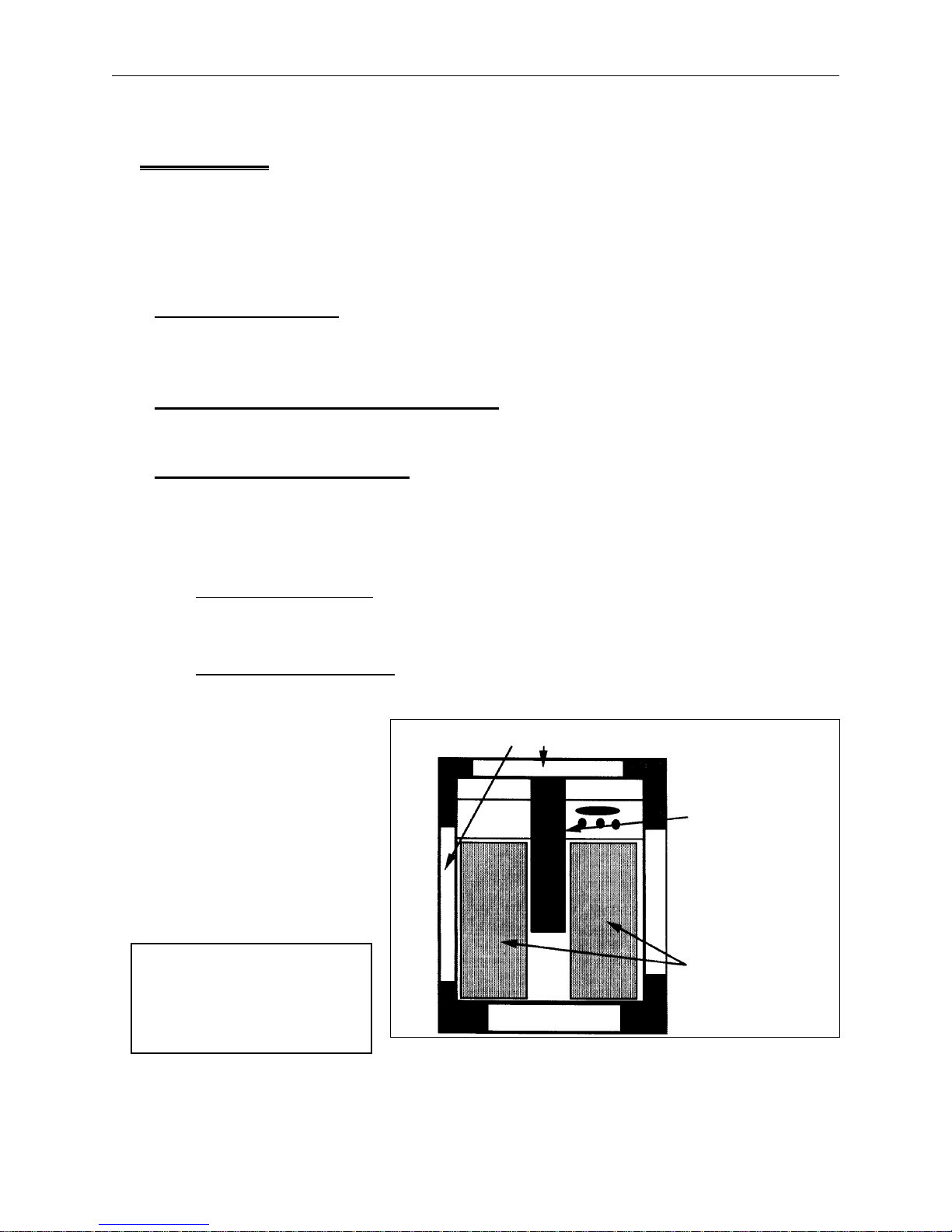
When to Use The Move Menu
The Move Menu allows precise placement of a design by repositioning the embroidery area under
the needle.
In Figure 4-1, the machine has already embroidered a three-letter monogram on the forward, left
side of the embroidery field.
Figure 4-1
The dashed lines show the center of the embroidery field. The box with three small plus signs (+) in
the rear, right shows the next position of the design.
1. After the first design finishes embroidering, the LCD displays: END OF DESIGN.
2. Press [MENU] to scroll to the Move Menu. The LCD displays: MOVE MENU.
3. Press [ENTER] and the LCD displays: MOVE X +00.00 IN.
4. If necessary, press [
5. Press and hold the [
⇒] to make the value positive.
⇑] key and the value increases rapidly. Stop at +2.00. The display now reads:
MOVE X +02.00 IN.
NOTE: Keep in mind that the X movement of the carriage is in reference to the needle position.
That means, for the needle position to move to the right in the embroidery field, the
carriage must move to the left.
6. Press [ENTER] and the LCD displays: MOVE Y +00.00 IN.
7. If necessary, press [
⇒] to make the value positive.
8. Press and hold [
⇑] until the value reaches +2.50. The display now reads: MOVE Y +02.50 IN.
Page 43

Setting the Options 4 - 7
110265-01, Rev. A 4. The Customizing Menus
This Y Move positions the needle to the rear of the embroidery field. If the value was negative, the
Y Move would position the needle to the front of the embroidery field.
9. Press [ENTER].
10. Press [START]. The machine moves in both the X and Y axes to reposition the hoop.
After the Move Menu repositions the hoop, use the Trace Menu to verify the design fits in the
embroidery field, then press [ENTER] and then [START] to begin embroidering.
NOTE: If the LCD displays: MACHINE RUNNING, either a job is in progress and must be canceled
(see Reset Menu); or a move has been entered but not executed using the [START] key.
Trim Menu
When designs are created, trim commands may be included as part of the design. When the
Advantage 18 reads these commands, a trim occurs automatically. The trimmer function performs
when it encounters:
• A color change
• A set of commands called a trim dataset
• The start and the end of the design
• The number of consecutive jump stitches set in the jump count option
• A trim immediate selection, if the machine is not embroidering
• A change thread selection, if the machine is not embroidering
Setting the Options
Scroll through the top level menus, or press [ENTER] from the Head Timing Menu to reach the Trim
Menu.
Use the Trim Menu only when the machine is idle. If you try to enter the Trim Menu while the
machine is embroidering, you will receive the error message: MACHINE RUNNING.
1. Press [MENU] until the LCD displays: TRIM MENU.
2. Press [ENTER].
Trim Immediate
3. Press [
⇓] and the LCD displays: TRIM IMMEDIATE. Press [ENTER] to activate the trimmer. Trim
Immediate can only be activated when the embroidery head is stopped.
Jump Count
4. Press [
⇓] again and the LCD displays: JUMP COUNT. This option allows you to select the number
of consecutive jump stitches that will force an automatic trim. The machine trims before the
jump stitches occur. The default jump count is 8.
Page 44

4 - 8 The Splicing Menu
Advantage 18 Operation Manual Melco Embroidery Systems
Acceptable values are 0 through 15, but a value of 0 disables the function. Pressing [⇒] will
increase the count by one, pressing [
⇐] will decrease the count by one.
5. Press [MENU] to exit the Trim Menu.
Bobbin Menu
This feature is not available with the Advantage 18 and must remain OFF at all times. If the Bobbin
Control is ON, follow these steps to turn it OFF:
1. Press [MENU] until the LCD displays: BOBBIN MENU.
2. Press [ENTER].
3. Press [
4. Press [
⇑] until the LCD displays:BOBBIN CTRL ON.
⇒] to turn the feature OFF.
5. Press [ENTER] to leave the menu.
The Splicing Menu
Scroll through the top level menus, or press [ENTER] from the Trim Menu to reach the Splicing
Menu.
The Splicing Menu provides:
• The ability to change the current thread color
• An alternative way to insert thread through the splicing chamber
• A way to toggle on or off certain functions
• A tool for troubleshooting that can activate valves, motors, and trimmers
The Splicing Menu options are:
• Change Thread
• Insert Thread
• Valve ON/OFF
• Upper Trim Motor ON/OFF
• Trim Thread
• Draw Motor
• Low Pressure ON/OFF
• High Pressure ON/OFF
Page 45

Change Thread 4 - 9
110265-01, Rev. A 4. The Customizing Menus
Change Thread
If you want to change the thread that is currently embroidering, use the Change Thread option. For
instance, you might want to embroider with two colors in a design with no color change
commands. The Change Thread option performs a color change, then embroiders with the new
color until it reaches a color change command or the end of the design. Using the change thread
option does not alter the color sequence, nor is it used again if the color sequence wraps.
Follow these steps to use the Change Thread option:
1. If the machine is embroidering, press [STOP].
2. Press [MENU] until the LCD displays: SPLICING MENU.
3. Press [ENTER] and the LCD displays: CHANGE THD: 0.
4. Press [
⇐] or [⇒] to decrease or increase the thread position value. Press and hold to scroll
through the values. Release the key when the desired thread position is displayed.
CAUTION! The following step includes making trims and stitches. Keep the
embroidery area clear.
5. Press [ENTER] to execute a color change.
NOTE: Press [ENTER] when the Change Thread value is in the range of 1 to 18 to execute
a color change to that thread position. No color change takes place if:
* The value is set to 0.
* There is an asterisk next to the value as in: CHANGE THD: 5*. The asterisk means the
carriage selector is at that thread position.
6. Press [ALT][ENTER] to return to the Idle Menu.
7. Press [START] to resume embroidering with the new color.
If you are in a design and use the [FAST\SLOW] key to insert the thread after the Change Thread
option performs, the selector moves to the Change Thread selection. If you are not in a design, the
selector carriage moves to the previous thread position.
Page 46

4 - 10 The Splicing Menu
Advantage 18 Operation Manual Melco Embroidery Systems
Insert Thread
Use this option to insert a thread into the splicing cell. It performs the same function as [ALT][
[ALT][
⇒], or [FAST/SLOW] discussed in the Threading the Advantage 18 section of this manual.
⇐],
To use the Splicing Menu follow these steps:
1. Press [MENU] until the LCD displays: SPLICING MENU.
2. Press [ENTER].
3. Press [
⇑] and the LCD displays: INSERT THREAD.
4. Secure the thread under the pretensioner, in the groove, and through the thread guide hole.
Trim to 1/8 inch.
5. Move the selector carriage to that thread position.
6. Press either [
⇐] or [⇒] to insert the thread through the splicing cell.
7. Complete the manual threading process.
Valve 1 Off
This option can turn each of the six air pressure valves ON and OFF. The default is OFF. These valves
normally function automatically during a thread splice or insert. If you are troubleshooting one of
these processes, test the valves individually. If they are working properly, you will hear a hiss of
compressed air or a mechanical action such as a moving clamp as each is turned ON. If there is no
reaction when turning ON a valve, call your Melco service representative. To activate this option:
1. Press [MENU] until the LCD displays: SPLICING MENU
2. Press [ENTER].
3. Press [
4. Press [
5. Press [
6. Press [
⇑] until the display reads: VALVE 1 OFF
⇒] to turn value 1 ON and listen for a moving clamp.
⇐] to turn valve 1 OFF.
⇑] to move to another valve and repeat steps 3 and 4, each time listening for a
compressed air hiss or a mechanical action.
7. Press [ENTER] to leave this option.
Page 47

Trim Thread 4 - 11
110265-01, Rev. A 4. The Customizing Menus
Up Trim Mtr On
This display is to verify that the upper trim motor is functioning. When you toggle it ON, the motor
runs for about 15 seconds, producing an audible buzzing sound. It does not perform a trim. If you
do not hear the motor start, call your Melco service representative.
CAUTION! Do not allow the motor to run continuously or the drive
electronics may overheat.
1. Press [MENU] until the LCD displays: SPLICING MENU.
2. Press [ENTER] until the LCD displays: UP TRIM MTR OFF.
3. Press [
4. Press [
⇒] to turn the motor ON, and listen for the motor.
⇐] to turn the motor OFF.
5. Press [ENTER].
Trim Thread
This option performs an upper trim when the machine is completely threaded and you press either
the [
⇐] or [⇒] key.
1. Press [MENU] until the LCD displays: SPLICING MENU.
2. Press [ENTER].
3. Press [
4. Press either [
5. Press either [
⇑] until the display reads: TRIM THREAD.
⇐] or [⇒] and the machine displays: TOP TRIM PAUSE.
⇐] or [⇒] again, to perform a trim.
The upper trimmer has separate left and right cutting edges. You may get a successful trim when
moving
left from thread to thread, but not when moving right, or vice versa.
When you press [
⇐] or [⇒] to perform the trim, you are also selecting the left or right cutting edge
of the trimmer. To troubleshoot an upper trimmer problem, rethread the machine and trim at the
same thread using the other arrow key.
6. Remove the trimmed pieces from the splicing cell and the rest of the machine, and rethread the
machine.
You may move the selector carriage and repeat this process, but you must clear away all trimmed
threads and rethread the machine each time.
If the trimmer is not performing correctly, call your Melco service representative.
Page 48

4 - 12 The Splicing Menu
Advantage 18 Operation Manual Melco Embroidery Systems
Draw Motor
The draw motor moves the thread through the splicing cell and along the thread path. This option
allows you to check that the draw motor is working properly. If it is not, call your Melco service
representative.
With a thread through the splicing cell:
1. Press [MENU] until the LCD displays: SPLICING MENU.
2. Press [ENTER].
3. Press [
4. Press [
5. Press [
⇑] until the LCD displays: DRAW MOTOR.
⇒] and the thread should move forward.
⇐] and the thread should move backward.
Low Pressure On
The Advantage 18 has a sensor that detects when the compressed air pressure falls below 75 psi.
When this happens the LCD displays: PRESSURE LOW!
This message will only display before a function that requires compressed air. The purpose of the
sensor is to tell you the air pressure may be too low to make a good thread splice. You must
respond to this message before the Advantage 18 will resume embroidering.
If PRESSURE LOW! is displayed, check your air compressor regulator and make any necessary
adjustment. When the air pressure returns to the 75 psi to 95 psi range, the message remains until
[START] is pressed.
If you check your air pressure regulator and find the pressure is between 75 psi and 95 psi, you
may have a broken sensor. Call your Melco service representative to order a new pressure sensor.
Meanwhile, this option allows you to turn the sensor OFF and continue embroidering.
1. Scroll to the SPLICING MENU.
2. Press [ENTER].
3. Press [
4. Press [
⇑] until the LCD displays: LOW PRESSURE ON.
⇐] to disable the sensor. The LCD displays: LOW PRESSURE OFF.
NOTE: When you want to enable the sensor, press [
LOW PRESSURE ON.
5. Press [ENTER] to leave this option.
The sensor will stay OFF until you reconfigure or perform a hard reset.
⇒] and the display will once again read:
Page 49

System Reset 4 - 13
110265-01, Rev. A 4. The Customizing Menus
High Pressure On
High compressed air pressure can also cause problems with splicing. If the compressed air is
detected above 95 psi, the LCD displays: PRESSURE HIGH!
You must respond to this message before the Advantage 18 will embroider again. Check the
regulator on your air compressor and make any necessary adjustment. When the air pressure
returns to the 75 psi to 95 psi range, the message will remain until you press [START] to resume
embroidering.
If the air compressor regulator is between 75 psi and 95 psi, and you get this message, you may
have a broken sensor. Call your Melco service representative to order a new pressure sensor.
Meanwhile, this option allows you to turn the sensor OFF and continue embroidering.
1. Scroll to the SPLICING MENU.
2. Press [ENTER].
3. Press [
4. Press [
⇑] until the LCD displays: HI PRESSURE ON.
⇐] to disable the sensor. The LCD displays: HI PRESSURE OFF. Press [⇒] to enable the
sensor.
5. Press [ENTER] to leave this option.
The sensor will stay off until you reconfigure or perform a hard reset.
Reset Menu
The Reset Menu allows you to delete the current job in the run buffer, or to reset to the default
values.
System Reset
Performing a "System Reset" clears the run buffer, but it does not clear the design buffer. Scroll
through the top level menus, or press [ENTER] from the Splicing Design Menu to reach the Reset
Menu.
1. Press [MENU] until the LCD displays: RESET MENU.
2. Press [ENTER] and the LCD displays: SYSTEM RESET.
3. Press [ENTER] again and the LCD displays: **RESET**.
Page 50

4 - 14 Reset Menu
Advantage 18 Operation Manual Melco Embroidery Systems
Hard Reset
A Hard Reset resets all operator entered values to their default settings and clears the run buffer.
After a hard reset you must set home before you can embroider again.
1. Use the [MENU] key to scroll to the Reset Menu. Press [ENTER] to display the SYSTEM RESET
message.
2. Press [
⇑] or [⇓] and the LCD displays: HARD RESET.
3. Press [ENTER] and the LCD displays: **RESET**.
4. Press [ENTER] again and the LCD displays: MEMORY CLEARED.
The Advantage 18’s stitch count is cleared from memory and the operator supplied parameters are
restored to default values in the Move, Trace, Home, Color, Tension, Orientation, and Splice menus.
Page 51

5 - 1
110265-01, Rev. A 5. Operator Maintenance
5. Operator Maintenance
To keep the Advantage 18 running at peak efficiency, maintenance procedures must be performed
on a routine basis. This chapter covers operator maintenance and service.
Warning! Avoid personal injury by turning the machine OFF
and unplugging it before removing covers.
Cleaning Exterior Surfaces
Clean outer plastic surfaces with a soft, clean cloth, a mild detergent and water. Wring out the
cloth before wiping the surfaces. Do not get water or any other fluids inside the machine or on any
of the working mechanical surfaces.
NOTE: In the event of an accidental spill, mop up the excess fluid with a clean dry cloth and
allow the machine to dry completely before turning on the power. If the fluid gets
inside the plastic covers, remove the covers to access the interior. Contact your Melco
representative for recommendations.
Cleaning the Rotary Hook Area
1. Turn the machine power OFF.
2. Remove the 2 screws holding the needle plate and lift it off the cylinder arm. Set the needle
plate aside.
3. Clean the area with the brush supplied in the operator’s kit.
Cleaning the Color Change Area
As you embroider with your Advantage 18, the area under the color change cover will accumulate
lint and bits of thread. Clean this area two or three times a week, and anytime you are having a
color change or thread splicing problem.
Page 52

5 - 2 Cleaning the Color Change Area
Advantage 18 Operation Manual Melco Embroidery Systems
Color Change Cover Removal
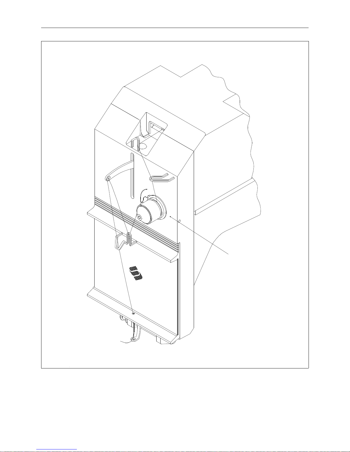
Refer to Figure 5-1 in removing the color change cover.
Thread
Select
Carriage
Aim compressed
air into this
opening for
cleaning
cover
screws
Color
Change
Cover
1. Slide the thread select carriage to the left of the head to remove it from the manifold assembly.
2. Remove the two socket head screws from the color change cover.
3. Lift the rear of the cover about 3 to 3 1/2 inches as indicated in circle inset in Figure 5-1. Lift the
cover straight up to remove it.
Figure 5 - 1
Page 53

The Manifold 5 - 3
110265-01, Rev. A 5. Operator Maintenance
The Manifold
The manifold is the under the color change cover. See Figures 5-2 and 5-3.
The manifold shown with the
color change cover removed.
Figure 5-2
A close-up view of the manifold.
Keep this area free of lint or debris.
Figure 5-3
The manifold holds valves and rollers, the splicing cell, and various other small parts. They may not
work at their peak efficiency if the area becomes contaminated with lint. Use a can of compressed
air to blow away any lint or thread. You can do this without removing the color change cover. Aim
the air into the opening in the needle case above the first thread guide as shown in Figure 5-1.
As you engage the air, move the can so that the air reaches all areas under the cover. At the back
of the manifold, clean the area in and around the openings by the carriage selector. If color change
or thread splicing problems continue, remove the cover and clean the area more thoroughly. Pick
away any threads that the compressed air leaves behind. Reinstall the cover after the area is clean.
Page 54

5 - 4 Cleaning the Color Change Area
Advantage 18 Operation Manual Melco Embroidery Systems
Upper Trimmers
The upper trimmers clip the old thread during a color splicing cycle. If the trimmers have lint or
pieces of thread on them, they may not operate efficiently and the color change may not be
successful. The upper trimmers are at the back of the manifold, where the thread enters the
splicing cell. Refer to Figure 5-4 while you perform the following steps:
Splicing cell
Toward the front of
the embroidery head.
Figure 5-4
Aim compressed air into these
openings to clean trimmer area.
Upper Trimmer
Toward the selector carriage and
the rear of the embroidery head.
1. To locate the trimmers, stand at the side of the machine, just behind the manifold and look
toward the front of the embroidery head.
2. Spray air into both holes at the top of the trimmer.
Do this two or three times a week, or any time you are having color change or thread splicing
problems.
Page 55

Pretensioner 5 - 5
110265-01, Rev. A 5. Operator Maintenance
Pretensioner
After the threads exit the tubes coming from the thread tree, the pretensioner rests on the threads
holding them for insertion into the selector carriage. If lint or other debris accumulates on the
pretensioner, the threads may not be held properly. To clean the pretensioner, perform these steps
two or three times a week, or if you are have thread splicing problems. Refer to Figure 5-5.
The pretensioner, shown lifted
above the selector carriage.
Figure 5-5
1. Turn the Advantage 18 OFF.
2. Move the selector carriage to the side.
3. Use a can of compressed air to blow away any lint or debris.
4. Lift the magnetic strip and clean it using the lint brush provided in the operator’s kit.
5. Clean the metal under the threads with a soft cloth and an alcohol wipe.
6. Replace the pretensioner and the embroidery threads.
7. Turn the Advantage 18 ON.
8. Rethread the machine.
Lubrication
Follow the schedules in each lubrication section to prolong the life of your machine. Any tools or
supplies needed are provided in the operator’s kit.
Page 56

5 - 6 Lubrication
Advantage 18 Operation Manual Melco Embroidery Systems
Lubricating The Embroidery Head
The table below is a lubrication schedule for areas of the embroidery head.
Embroidery Head Lubrication Schedule
Lubrication Point Lubricant Frequency
Rotary hook Sewing Machine Oil Every 4 operating hours
Needle bar Sewing Machine Oil Every 80 operating hours
Needle bar driver Sewing Machine Oil Every 80 operating hours
Connecting rod upper hole Sewing Machine Oil
Connecting rod lower hole Sewing Machine Oil
Rotary Hook
1. Slide out the table insert to gain access to the rotary hook area.
2. Remove the bobbin case and bobbin from the hook assembly.
3. Turn the Advantage 18 ON.
4. Press [MENU] until the LCD displays: HEAD TIMING MENU.
5. Press [ENTER].
6. Press [ALT][
⇓] 2 times to rotate the hook assembly into position.
7. Place one drop of oil at the location on the hook assembly shown in Figure 5-6.
Place 1 drop of
oil here every 4
operating hours
Rotary Hook
Assembly (bobbin
case removed)
8. Replace the bobbin and bobbin case.
9. Replace the table insert.
Figure 5-6
Page 57

Lubricating The Embroidery Head 5 - 7
110265-01, Rev. A 5. Operator Maintenance
Needle Bar
Lubricate the needle
bar at both the upper
and the lower
locations shown in
Figure 5-7. Slightly
bend the oiler tube
to make it easier to
reach the needle bar.
Place 1 or 2 drops on
the upper location.
To lubricate the lower
location, slide the
front cover of the
needle case to one
side. Place 1 to 2
drops on the needle
bar or on the felt.
Needle Bar
upper
lubrication
location
Cutaway of the
needle case showing
the needle bar.
Needle Bar
lower
lubrication
location
Needle Bar Driver
The needle bar driver is located inside the
head casting, directly behind the needle
bar. It has a spiral groove around its shaft
(see Figure 5-8). Access it through the
take-up lever slot.
Put 3 to 5 drops onto the shaft.
Figure 5-7
The needle bar
driver is behind
the needle bar.
Lubricate it at
this point.
Cutaway of
the needle
case showing
the needle
bar.
Figure 5-8
Page 58

5 - 8 Lubrication
Advantage 18 Operation Manual Melco Embroidery Systems
Upper Connecting Rod
1. Slide the front cover of the
needle case to one side to
access the needle bar driver
area (see Figure 5-9).
2. Press [MENU] until the LCD
displays: HEAD TIMING MENU.
3. Press [ALT][
⇑].
Upper Connecting
Rod lubrication hole
4. Press [ALT][
5. Press [
⇓].
⇒] to place the
lubrication hole directly
behind the slot in the plastic
guide. It is located just to the
right of the needle bar driver
as shown in Figure 5-9.
6. Put 1 to 3 drops at the hole in
the top of the connecting rod.
7. Slide the front cover back in
place.
Lower Connecting Rod
1. Press [MENU] until the LCD
displays: HEAD TIMING MENU.
Cutaway
of the
plastic
guide to
show the
lubrication
hole.
Figure 5-9
Lower Connecting
Rod lubrication hole
2. Press [ALT][
3. Press [ALT][
4. Press [
⇑].
⇓].
⇒].
5. Locate the lower lubrication
hole of the connecting rod. It
is behind the access hole on
the left side of the embroidery
head as shown in Figure 5-10.
6. Put 1 to 3 drops into the
lubricating hole.
Hole in casting for
lubrication access
Figure 5-10
Page 59

Lubricating The Beam 5 - 9
110265-01, Rev. A 5. Operator Maintenance
Lubricating The Beam
Lubricate the beam regularly as described in the following schedule. Refer to Figure 5-11 to identify
the locations.
Drive pulley shaft, front & rear Sewing Machine Oil Every 160 operating hours
Idler pulley Sewing Machine Oil Every 160 operating hours
Rollers: left, right, front, & rear Sewing Machine Oil Every 160 operating hours
Left & right Y rails, front & rear Sewing Machine Oil Every 160 operating hours
Drive Pulley Shaft,
front & rear
Left Y Rail,
front and rear
Left Rollers,
front & rear
Right Rollers,
front & rear
Idler Pulley
Right Y Rail,
front and rear
Figure 5-11
Page 60

5 - 10 Lubrication
Advantage 18 Operation Manual Melco Embroidery Systems
Drive Pulley Shaft
1. Turn the power switch to OFF.
2. Remove the X-drive cover (see Figure 5-12).
X Drive Cover
Cover Screws
Figure 5-12
Locking Tab
Beam
3. Move the X-carriage manually all the way to the left.
4. In turn, insert the oil tube through each of the two drive pulley shaft access holes and place one
drop of oil on top of the pulley shaft at each location (see Figures 5-13 and 5-14).
Figure 5-13
Page 61

Lubricating The Beam 5 - 11
110265-01, Rev. A 5. Operator Maintenance
Figure 5-14
Idler Pulley
5. Repeat the procedure for the idler pulley on the right side of the beam assembly (see Figure
5-15).
Figure 5-15
Page 62

5 - 12 Lubrication
Advantage 18 Operation Manual Melco Embroidery Systems
X-Carriage Rollers
Refer to Figure 5-15 and lubricate the four X-carriage rollers with one drop on each roller as shown
in Figure 5-16.
Figure 5-16
Y-Rails
Access the Y-rails
through the slots on
either side of the beam.
Refer to Figure 5-17 for
the specific points of
lubrication. Place 1 to 2
drops on each side of
the Y-carriage.
Figure 5-17
Page 63

Lubricating the Lower Trimmers 5 - 13
110265-01, Rev. A 5. Operator Maintenance
Lubricating the Lower Trimmers
The lower trimmer assembly is located under the embroidery bed as indicated in Figure 5-18.
Lubricate the lower trimmer parts according to following schedule:
Lower Trimmer Lubrication Schedule
Lubrication Point Lubricant Frequency
Trimmer Cam Grease Every 6 Months
Trimmer Knife Arm Rear
Sewing Machine Oil Every 40 Operating Hours
Pin
Trimmer Knife Arm Front
Sewing Machine Oil Every 40 Operating Hours
Pin
Trimmer Knife Drive Arm Sewing Machine Oil Every 40 Operating Hours
Trimmer Picker Base Shaft Sewing Machine Oil Every 40 Operating Hours
Rear Bed Cover
Needle Plate
Figure 5-18
Page 64

5 - 14 Lubrication
Advantage 18 Operation Manual Melco Embroidery Systems
The Rear Trimmer Parts
Remove the rear bed cover to access the trimmer areas shown in Figure 5-19.
1. Place a dollop of grease on the trimmer cam.
2. Place a drop of sewing machine oil on the rear pin of the trimmer knife arm.
Trimmer Cam groove
Trimmer Knife
Arm, Rear Pin
Figure 5 - 19
The Front Trimmer Parts
Remove the needle plate to access the trimmer areas shown in Figures 5-20, 5-21, and 5-22. Place
a drop of sewing machine oil in each of the indicated locations.
Trimmer Knife
Drive Arm Shaft,
top view.
Trimmer
Knife Drive
Arm Shaft,
side view.
Trimmer Knife Arm, Front Pin
Figure 5-20
Lubricate both
locations
Figure 5-21
Page 65

Machine Out Of Timing 5 - 15
110265-01, Rev. A 5. Operator Maintenance
Picker Shaft. Place
Place oil at the
pivot of the
Picker Base
Figure 5-22
oil at the hole in the
top of the mount.
Head Timing
Embroidery Head Timing covers these related topics:
• Headup
• Needle Depth
• Hook Timing
• Hook Gap
The embroidery head must be correctly set to the headup position before adjusting any other
settings. The head must be timed properly to produce quality embroidery.
NOTE: Headup is a factory setting and should not be changed or adjusted unless the headup
encoder has been replaced. When the headup position is reset with the new encoder, it
should not have to be set again. Before you attempt any changes to headup, check
with your Melco representative for advice.
Needle depth may require readjusting if you hit the hoop with the needle, or change needle sizes,
types, or brand. Changing types of needles or threads can also require resetting the hook gap of
the rotary hook.
Machine Out Of Timing
It is rare for the machine to go out of timing, but the most frequent cause is when the needle
strikes the hoop while embroidering. When this happens the machine stops abruptly, jarring the
mechanical parts.
Even if the machine does not go out of timing, replace the needle after striking the hoop.
If the presser foot and the hoop collide, the presser foot may bend enough to rub the thread or
needle.
Page 66

5 - 16 Head Timing
Advantage 18 Operation Manual Melco Embroidery Systems
Before adjusting head timing, check the following:
• Tension settings (upper and lower)
• Needle condition, size, and type of point
• Lubrication of hook assembly and head
• Nicks in the presser foot or needle plate
• Presser foot height
• Stitch density
• Proper embroidery technique for the material being used (i.e. backing material, type and
size of thread)
• Material improperly hooped
• Needle Bar depth incorrect
Making A Stitch
How well the embroidery head makes a stitch depends on the needle/hook relationship. Figure
5-23 shows how the embroidery head makes a single stitch. Understanding this stitch cycle will
help produce quality embroidery.
The needle moves down through the fabric and then starts back. This action creates a small loop in
the thread behind the needle. The degree of tightness of the loop depends on thread tensions.
When the loop forms, the rotating hook must be in position to catch the thread. Once the hook
catches this loop, it wraps the thread around the bobbin case, capturing the bobbin thread. As the
needle rises, the loop is lifted by the take-up lever with the bobbin thread inside it. This procedure
repeats for each stitch.
Figure 5-23
Page 67

Needle Depth Check/Adjustment 5 - 17
110265-01, Rev. A 5. Operator Maintenance
Needle Depth Check/Adjustment
Needle depth is a basic operator adjustment required to achieve quality embroidery. The needle
depth setting is the relationship between the eye of the needle and the hook when the needle is at
its lowest point. Because there is a wide range of acceptable needle types, the distance between
the point and the eye of the needle may vary enough to cause missed stitches or cut threads if the
needle depth is not correct. Follow these steps to adjust needle depth:
1. Remove the front cover of the needle case.
2. Remove the center table section from the peripheral.
3. Remove the bobbin case from the rotary hook assembly.
4. With the machine ON and ready for operation, press [MENU] at the peripheral keyboard until the
LCD displays: HEAD TIMING MENU.
5. Press [ENTER] and the LCD displays: HEAD TIMING ON.
6. Press [ALT][
⇑]. The embroidery head rotates to the "headup" position and the LCD displays: GO
TO HEADUP.
7. Press [ALT][
⇐]. The embroidery head rotates one revolution. The LCD displays: ONE
REVOLUTION. The needle bar should be down with the presser foot about 1/4 inch from the
needle plate.
8. Press [ALT][
⇓]. The embroidery head rotates to the "needle depth" position and the LCD
displays: NEEDLE DEPTH. The needle has reached it lowest point.
9. Look directly into the hook assembly and check the location of the needle’s eye compared to
Figure 5-24.
If 1/4 to 3/4 of the needle eye is showing in the bobbin cavity, no adjustment is required. Skip
steps 9 through 16.
If the needle eye is not in the acceptable range, go to step 10.
Figure 5-24
Page 68

5 - 18 Head Timing
Advantage 18 Operation Manual Melco Embroidery Systems
10. Loosen the needle clamp screw on the
needle bar as shown in Figure 5-25.
11. Slide the needle bar up or down until
1/2 of the needle’s eye is visible in the
bobbin cavity. Do not twist the needle
bar.
12. Retighten the needle clamp screw.
Make sure the needle bar is still in the
correct position.
13. Go to the "Hook Timing" position by
pressing [ALT][
⇒]. The LCD displays:
HOOK TIMING.
Upper Dead Stop
Clamp Screw
Needle Clamp
Screw
14. Press [
⇒] 8 times. The LCD displays: 10
STEPS FORWARD each time the key is
pressed.
15. Loosen the black screw on the
upper-dead-stop clamp. See Figure
5-25.
16. Press [
⇒] one more time. This rotates
Figure 5-25
the embroidery head to the full needle
up position.
17. Slide the clamp up firmly against the upper stop and tighten the screw on the upper-dead-stop
clamp. Make certain the screw points straight outward.
18. Press [ALT][
⇑]. The embroidery head rotates to Headup.
Page 69

Hook Timing 5 - 19
110265-01, Rev. A 5. Operator Maintenance
Hook Timing
The hook timing adjustment should not change when adjusting the needle depth position, but it
would be a good idea to check it and make sure. Figure 5-26 shows the stitch/cycle relationship.
Figure 5-26
The hook point is not fully drawn in this illustration, but its position is indicated. In order for the
hook point to catch the loop of thread, it must pass through the needle scarf area approximately
1/8 inch (3.175 mm) above the eye, after the needle rises 3/32 inch (2.38 mm).
Checking Hook Timing
1. Install a new needle to better evaluate the needle/hook point positioning.
2. Remove the table insert, bobbin case, and needle plate.
3. Turn the embroidery peripheral ON and select the Head Timing Menu from the keyboard.
4. Press [ALT][
⇐] to cycle the head one revolution. The machine will go to headup without
engaging the jump stitch solenoid.
5. Press [ALT][
⇓] to cycle the head to the full needle down position.
Page 70

5 - 20 Head Timing
Advantage 18 Operation Manual Melco Embroidery Systems
6. Press [ALT][⇒] and the LCD displays: HOOK TIMING.
The hook point should:
• Have a gap between it and the needle approximately the thickness of the thread. Check
the gap by positioning a length of embroidery thread below the hook, between it and
the needle. Lift the thread slowly by both ends. It should pass through the gap between
the needle and the hook, just slightly catching between the two. The thread should form
a V briefly before it pulls free. If the gap needs to be adjusted, hook timing may also be
required.
• Be directly behind the needle within about 1/2 the thickness of the needle as shown in
Figure 5-27. If this is not the case, the hook timing must be adjusted.
Figure 5-27
Page 71

Hook Timing 5 - 21
110265-01, Rev. A 5. Operator Maintenance
Adjusting Hook Timing
Hook timing may be improperly adjusted if the needle depth is incorrect, so always check the
needle depth first. The following steps assume the rotary hook is installed in the approximate
position for embroidering. Refer to Figures 5-28 and 5-29. If you have not already done so, remove
the table insert, needle plate, and bobbin case.
The Hook Point
Figure 5-28
The screws that must be loosened
to adjust or remove the hook
Figure 5-29
You may occasionally remove the hook to clear away a birdsnest of thread or for some other
reason. When replacing the hook assembly, slide it back on the shaft in the approximate position
for embroidering and tighten one of the screws. Attach the retaining finger so the tab is holding
the inner basket of the hook assembly.
1. Turn the Advantage 18 power ON and press [MENU] until the LCD displays: HEAD TIMING.
2. Press [ALT][
⇒] and the LCD displays: HOOK TIMING. Press [ENTER] three times, then loosen (but
do not remove) the first hook mounting screw on the right side.
3. Press [ENTER] three more times and loosen the second screw on the right side.
4. Press [
⇒] until the LCD displays: GO TO HEADUP, then press [ENTER]. Press [⇒] until the LCD
displays: BOTTOM DEAD CENTER, then press [ENTER].
5. Loosen the third mounting screw (now accessible from the right).
6. Verify the retaining finger tab is still securing the inner basket of the rotary hook. If the inner
basket moves, it may result in a broken needle or damaged hook.
Page 72

5 - 22 Head Timing
Advantage 18 Operation Manual Melco Embroidery Systems
7. Position the hook directly behind the needle. The indentation for the retaining finger tab should
be directly in front of the needle. Hold the hook in this position.
Hook Point
Figure 5-30
Needle
Indentation for the
retaining finger tab
8. Slide the hook assembly forward or backward until you have a gap about the thickness of a
thread between it and the needle. You may have to tighten one of the screws slightly and
check the gap before it is correct.
9. When the gap is correct, tighten the screws. Use the Hook Timing commands as described in
steps 1 through 4 in order to access all of the screws.
10. If you loosened or removed the retaining finger during hook timing and hook gap adjustments,
you must now readjust the tab gap. The retaining finger tab should:
• Be in the groove far enough to keep the inner basket from rotating.
• Leave a space large enough for thread to pass.
11. Check all of your adjustments (referring to Figure 5-27) and repeat any steps if necessary.
12. Replace the needle plate, making certain the needle centers in the needle plate hole. When the
needle is centered, tighten the plate completely.
13. Replace the bobbin case and the table insert.
Page 73

A - 1
110265-01 Rev. A A. Glossary of Embroidery Terms
A. Glossary of Embroidery Terms
ACTIVE WINDOW
The window that you are currently using. Also called the current window.
ALPHABETS
Lettering styles that are ready to use for embroidery. Alphabets can also be designs that are
brought to the screen using letters of the alphabet. An example of this would be Sports Symbols.
APPLICATION WINDOW
The first window to appear when EDS III is opened. The Application Window has three menu bar
items; File, Peripheral, and Help.
APPLIQUE
The art of using fabrics to enhance a design or to reduce the stitch count.
ARTWORK
A design or cartoon used to digitize.
AUTO DELETE
An option that automatically deletes designs from the sewing peripheral after the design has sewn
once.
AUTO RUN
An option that automatically sends a design to the beginning of the job queue, allowing you to
sew without making any selections from the peripheral menus.
AUTO TRIM
An option that automatically inserts a trim command between each alphabet letter used in a
design.
ARC ANGLE
The location of the center of lettering sewn on a circle. This position is entered in degrees,with 0
degrees the top of the circle and 180 degrees the bottom.
ARC FROM CENTER
When the position of the needle prior to sewing is at the center of the circle. The distance from the
center of the circle to the bottom of the lettering is the radius.
ARC NORMAL
When the position of the needle prior to sewing is on the circumference of the circle.
ASD
The file extension given by EDS III to a design that is sent to the peripheral.
BACKING
Fabric used for stabilizing that is added to the back of a garment to be embroidered.
Page 74

A - 2
Advantage 18 Operation Manual Melco Embroidery Systems
BEAN STITCH
A form of running stitch where the stitch is made forward, then back to the original needle
penetration point, then forward again. Also known as a triple run.
BIRD NEST
A tangled mass of thread that gets jammed in the needle plate. Sometimes it is caused by improper
tensions.
BIT PAD
Another name for a Digitizing Tablet.
BLOCK
A designated group of stitches that can be scaled, rotated, repositioned, deleted, cut, copied and
pasted.
BLOCK EDIT
The term used for changing a defined group of stitches.
BOBBIN
The reel or spool that holds the under thread of machine sewing. The under thread itself.
CENTER DESIGN
Positing the design in the center of the sewing field.
CHAIN STITCH
A stitch used to outline and detail a chenille design.
CHENILLE
A form of embroidery with a deep pile that uses heavy yarns and has no bobbin thread. Commonly
used for high school letter jackets.
CLICK
Pressing and releasing a mouse button in one quick motion.
CLIPBOARD
A temporary storage area in the computer’s memory. Data in the storage area can be copied to
another place.
CND
The three letter extension given to a Condensed file.
See Condensed Format for more information.
COLUMN FILL
An option to turn wide column or satin stitches into a series of shorter stitches.
COLUMN STITCH
A stitch formed with one needle penetration on either side of a column. Also referred to as a satin
stitch or a steil stitch.
Page 75

A - 3
110265-01 Rev. A A. Glossary of Embroidery Terms
COLUMN WIDTH
The width of the actual side-to-side needle penetrations in a column or satin stitch. In EDS III, the
width can be increased or decreased in increments of 10% from 90% to -90%.
COMPLEX FILL
A method for digitizing fills where the computer automatically determines the various independent
segments that are required in making the complete fill of an irregular shape.
CONDENSED FORMAT
A coding format that includes only the data for the Mk entries and function commands created
during digitizing. This format allows you to scale the design up or down as well as change the
density and stitch length of the design.
COPY
A command that keeps the design in the current window and also stores it in a temporary memory
called the clipboard.
CURSOR
An icon used to indicate your position on the computer screen.
CUT
An editing function used to take selected stitching out of a design and store it in the clipboard.
From there it may be pasted to a different place.
DATASET
A basic set of instructions to produce an embroidery design.
DEFAULTS
Values that are automatically used unless you override them with different values.
DENSITY
The vertical distance between two lines of stitching, measured in points.
DESIGN FILE
Any design stored on your hard disk or floppy disk. A file name can have up to eight letters, a
period, and a three letter extension.
DIALOG BOX
A box displayed on your computer screen that prompts you to give information, such as a selection
from a list of options, or a file name.
DIGITIZING
Converting artwork into a series of commands that can be read by an embroidery machine with the
use of a special device.
DIGITIZING TABLET
A board used to communicate with a computer or an embroidery machine while creating a design.
Page 76

A - 4
Advantage 18 Operation Manual Melco Embroidery Systems
DIGITRAC
The original Melco computerized digitizing system which uses an exceptionally large surface and its
own vertical stand.
DIRECTORY
A named group of computer files stored on one of your computer drives. The hard drive of your
computer is usually the C directory. Floppy diskettes are inserted into the A or B drive.
DISK
A computer data storage device which is accessed in the hard drive or one of the floppy drives.
DISKETTE FORMAT
The manner in which a disk has been prepared to accept information.
DITHERED COLORS
A combination of a solid color and a pattern.
DOUBLE CLICK
Pressing the mouse button quickly two times.
DRAG
Holding down the mouse button while moving the mouse. This is usually done to move an object
on the screen or to highlight text.
DROP-DOWN MENU
A list of available commands that displays when you click on a menu option. Commands displayed
in black are accessible, commands that are displayed in gray or half tone are not.
EDIT
Changing a design file by adding, deleting or moving Mk points, or by inserting and deleting
functions.
EMBROIDERY POINT
A unit of measure equal to one tenth of a millimeter or 1/254th of an inch.
EXP
The three letter extension given to an Expanded file.
EXPANDED FORMAT
A coding format that includes the data for every stitch in the design.
EXPORT
Copying a design from the computer to a non-DOS format diskette or paper tape.
EXTENSIONS
The last part of a file name after the period. It can be up to three characters long and is used to
identify the type of file.
Page 77

A - 5
110265-01 Rev. A A. Glossary of Embroidery Terms
FILE
A related collection of information, named and often stored on a disk.
FILE NAME
The unique identifier given to a design that is stored on a computer. The file name can have up to
eight characters, a period, and an up to three letters extension.
FILL STITCH
A series of running stitches used to cover large areas.
FORMAT
Preparing a disk to receive information. All new disks must be formatted, but reformatting a disk
destroys any information stored on it.
FUNCTION
An action caused by a command in a design such as Trim, Color Change, Needle Up, etc.
GRAPHICAL ROTATION
Angling a design in the Layout window using the mouse to click and drag the rotation box around
the object.
GRAPHICAL SCALING
Making a design larger or smaller in the Layout window using the mouse in a click and drag
motion.
GROUP OBJECTS
Objects that have been locked together on the screen.
HARD DISK
A sealed area in your computer containing a read/write head and auxiliary memory.
HOOP
A device made of wood, metal, or plastic used to hold a garment or fabric taut during the
embroidery process.
HORIZONTAL SPACING
Additional spacing that may be added between Alphabet letters.
ICON
A small graphic representation of something larger.
IMPORT
Bringing a design file into the EDS III program from a non-DOS formatted diskette or paper tape.
INSERT
Adding additional information to an existing design.
Page 78

A - 6
Advantage 18 Operation Manual Melco Embroidery Systems
JUMP STITCH
A frame movement without a needle penetration. Use of this function allows you to make a stitch
longer than the maximum stitch length of your machine.
LAYER BY COLOR
Used to show specific colors of a design on the computer screen.
LAYOUT WINDOW
The screen in which you can digitize designs, open files on the hard disk, import designs from
floppy disks, export designs, modify designs, and create lettering.
LETTER WIDTH
The overall width of each letter, NOT the column width. In EDS III changes to letter width can be
made in increments of 10% from +30% to -30%.
LINE CENTER BOTTOM
When lettering is centered horizontally and above the position of the needle prior to sewing.
LINE CENTER MIDDLE
When lettering is centered horizontally and vertically from the position of the needle prior to
sewing.
LINE NORMAL
When the bottom left of the lettering is the needle position prior to sewing. The sewing will stop at
the bottom right and will not return to the original position.
LINE SPACING
Adding space between lines of lettering. Line space is determined by adding the letter height to the
amount of blank space you want between the lines.
LIST BOX
A box, usually with a scroll bar, that appears within a dialog box and displays available options.
LOAD FILL
Accessing a fill pattern for inspection or changes.
LOCK GROUP
One or more objects that have been joined together.
LOCK STITCH
Three or more stitches placed closely together to prevent the embroidered stitches from pulling out.
Also know as a tie-off stitch.
MAXIMIZE
The small button to the right of the Title Bar with the up arrow. Used to enlarge a window to its
fullest extent.
Page 79

A - 7
110265-01 Rev. A A. Glossary of Embroidery Terms
MAXIMUM STITCH LENGTH
The longest stitch your embroidery machine is capable of sewing before performing a jump stitch.
The maximum stitch length for Melco is 127 pts.
MINIMIZE
The small button on the right of the Title Bar with the down arrow. Used to reduce a window to an
icon.
MODIFY MK BUTTON
An option that changes the position of a Mk point or changes the Mk to a different type of Mk.
MOSS STITCH
The "loopy" part of a chenille design. The height of the loop is controlled by the height of the
needle.
MULTIHEAD
An embroidery machine with more than one sewing head.
NEEDLE UP
A command used to move from one part of a design to another without stitching.
NON-DOS FORMATS
Any disk format other than DOS that is supported by EDS III, such as: Melco, Tajima, Barudan, ZSK.
NORMAL STITCH
A command that resets the stitching to a regular running stitch. It also brings the needle down to
the sewing position after a needle-up function is performed.
OBJECT
Any design from a disk, paper tape, or lettering brought in to the Layout window. Several objects
can be in one window at one time.
OBJECT FILE
A code format where each object has its own separate set of parameters. Condensed, expanded
and lettering designs can all be saved together as an Object File.
OBJECT ORDER
A list showing the sewing order of a group of objects.
OBJECT PARAMETERS
A dialog box which allows you to change the scale, rotation, orientation, or lock status of an object.
OFM
The three letter extension that identifies an Object file.
ORIENTATION
The direction that a design will sew. Melco uses an "F" to designate a normal sewing position.
Page 80

A - 8
Advantage 18 Operation Manual Melco Embroidery Systems
ORIGIN
The point at which a design will start. Most designs will have x and y coordinates of 0,0; meaning
that the design will start in the center and end in the center.
PAPER TAPE
An older form of computer information storage in which the information is stored as a series of
holes on a reel-to-reel paper tape.
PARTITION LINE SEQUENCE
Determines where the needle will penetrate on each line of stitching in a fill stitch.
PERIPHERAL
Any device that is attached to or run by the computer: Embroidery Machines, Paper Tape Punches,
Digitizing Tablets, Printers, or Plotters.
PERIPHERAL SETUP
A dialog box that allows you to select Embroidery Peripherals in your network.
PERIPHERAL STATUS
A dialog box that displays information about a particular peripheral.
POINT EDIT WINDOW
One of the windows that is used to edit designs.
RADIUS
The distance from the center to the circumference of a circle. The value of the radius controls the
amount of curve in an arc.
REGENERATE
A command to redraw a design, used to see modifications in the current design.
RESET STITCH
See Normal Stitch.
RETURN TO ORIGIN
A command used to move the pantograph back to the origin of the design.
RUBBER BANDING
A command to view an edited portion of a design without regenerating the entire design.
RUNNING STITCH
A line of equally spaced stitches that are used to outline, underlay or add detail to a design.
SATIN STITCH
A stitch formed with one needle penetration on either side of a column. Also called a column stitch
or steil stitch.
SAVE
A command to overwrite a previously saved file without prompting you for a new filename.
Page 81

A - 9
110265-01 Rev. A A. Glossary of Embroidery Terms
SAVE AS
A command to store a design for the first time, or to store a modified design with a new name to
prevent destruction of the original design.
SAVE FILL
A command to allow you to define fill information while digitizing.
SCALING
The process of changing the size, density or stitch lengths in a design.
SCROLL BAR
A bar that appears at the far right or bottom edge of a window or list box whose contents are not
fully visible. Clicking on the arrows of the bar moves the viewing portion of the screen.
SEND DESIGN
A command that loads a design in the active window into one or more peripherals. The design can
be a condensed, expanded, or object file.
SHORT STITCHES
Computer generated stitches that do not go all the way across a column at a curve or angle to
prevent an excess of stitches at one point.
SLANT ANGLE
A command that slants lettering in one degree increments up to fifteen degrees, positive or
negative.
SPECIAL STITCH
A user defined stitch that is digitized and stored temporarily in the computer memory. A Special
Stitch is limited to 30 Mks or commands.
STATUS BAR
The area at the bottom of the computer screen that displays information about the active window
or selected command.
STITCH
One needle penetration made by the embroidery machine.
STITCH COUNT
The number of stitches in a design.
STITCH LENGTH
The length of the running stitches in a design. Measured in points.
STITCH LIST (condensed)
Information showing the Mk points and functions that make up a design.
STITCH LIST (expanded)
Information showing the actual stitches and functions that make up a design.
Page 82

A - 10
Advantage 18 Operation Manual Melco Embroidery Systems
STITCH PROCESSOR
An EDS III option that changes the size, densities, or stitch lengths of an expanded design.
STORED SYMBOL
A portion of a design that is digitized as a separate piece to be used multiple times within the same
design. An example of this would be a leaves on a tree. You would digitize one leaf as a stored
symbol then use that same leaf and place it on the tree at various different sizes and angles. This
eliminates redigitizing the same design.
TIE OFF
See Lock Stitch.
TILE
Allows you to put up to nine windows in the Application Window.
TOOL SET
The commands and options on the left side of the window represented by icons.
TRANSFER DESIGN
A command that sends Expanded or ASD files to the Peripheral.
UNDERLAY
Stitches used to stabilize fabric and/or prepare the area for top stitching.
VERTICAL SPACING
A command that stair steps your lettering up (positive value), or down (negative value).
WINDOW
A rectangular area on your screen in which you view and work on designs.
ZOOM
A command that enlarges or reduces a portion of a design in the current Layout window, allowing
you to edit with more precision. This command does not affect the sewing size of the design.
Page 83

Bad PFR PTR B - 1
110265-01, Rev. A B. Error Messages
B. ERROR MESSAGES
When the Advantage 18 encounters an error, an error message displays on the LCD and the
machine beeps.
It may be an error in procedure. For example, an error message is displayed if you press the [START]
key before a design is loaded into the run buffer. You would respond by loading a design.
It may be a mechanical a problem. For example, an error message is displayed if the Y beam
reaches its limit before the design finished embroidering. You might need to use a larger hoop.
It may be a problem with the compressed air pressure. For example, an error message is displayed
when the air pressure falls below 75 psi. You should check the regulator on your air compressor.
The following pages contain an alphabetized list of the Advantage 18 error messages. If your
Advantage 18 displays an error message not listed here, or if you do not know how to respond to a
message listed here, contact your Melco service representative for assistance.
Application Run
Means that the peripheral did not download properly. Turn the Advantage 18 OFF, then ON again.
Call your Melco service representative if this message occurs often.
Bad Design Name
The design name was not found when the [START] key was pressed. If AutoDelete is ON at the
computer, the design is automatically deleted when it finishes embroidering. If AutoDelete is OFF,
the design was manually deleted from the Design Menu. Reload the design.
Bad Keyboard Code
Unable to read input from the keyboard. Turn the machine OFF then ON, and perform a power fail
recovery. If that does not fix the problem, reconfigure the machine. When you reconfigure, all
parameters will be reset to default values, and your design must be started from the beginning. If
that fails, call your service representative for help.
Bad PFR PTR
When you set the Power Fail Rescue (PFR) function on the Advantage 18, a pointer called a PTR is
inserted into the design program to mark where the last stitch was made. This message means an
error was detected while the pointer was being saved. To correct this problem:
1. Activate Return To Origin.
2. Frame through the design to the stopping point.
3. Press the [START] Key.
If that doesn’t work, turn the power OFF and then back ON.
Page 84

B - 2 Bad Z Creep Func
Advantage 18 Operation Manual Melco Embroidery Systems
Bad Z Creep Func
Means the Z axis command in the Head Timing Menu was slow in getting to the CPU. Wait 10
seconds and try again.
CC Pause
Displayed when the [STOP] key is pressed just before or during a color change. Press [START] to
continue the color change.
CC Pointer Error
The Advantage 18 has detected a software command error while trying to move the selector
carriage to a new position. Turn the power OFF and back ON.
CC Recovery
See CC Timeout.
CC Timeout!!
During a color change, the selector carriage did not finish its move within 5 seconds. This can be
caused by a jammed selector carriage or a malfunction of its motor or electronics.
If this message appears during the power-up and initialization sequence which happens when you
turn the power switch ON:
1. Turn the power OFF.
2. Manually move the selector carriage.
3. Turn the power back ON.
If this message appears during a normal color change, the current thread must be hand trimmed at
the end of the selector carriage, and the loose end removed from the splice cell and needle case.
Check the selector carriage again to make sure it is not jammed. Center the carriage and press the
[START] key. The selector should:
1. Move all the way to the right.
2. Move back to the color it was on before the error occurred.
3. Perform an Insert Thread through the splice cell.
4. Display: CC RECOVERY.
Manually thread the machine and press the [START] key again to continue embroidering.
If this message won’t clear after the above steps have been taken, turn the power OFF then ON. If
this error occurs frequently call your representative for assistance.
Page 85

Home Not Set B - 3
110265-01, Rev. A B. Error Messages
Cap Driver In
Means you have tried to SET HOME, GO TO HOME, or perform a POWER FAIL RECOVERY while the
cap frame drive is installed. Remove the cap frame driver before using these functions.
Color Change
***
The embroidery peripheral will stop after all subsequent color changes after the character P is read
in the color sequence. The embroidery peripheral will stop
encountered in the color sequence.
Color List Full
You cannot increase the color sequence to a value greater than 99.
Cutter Limit!
Means the drive circuit of the cutter trimmer solenoid has detected excess power. This is caused by
a malfunction of the cutter solenoid or electronics. Turn the Advantage 18 OFF, then ON to recover.
If this error occurs more than once during a design, call your representative for assistance.
***
one time after the character 0 is
Delete Failed
The machine was unable to delete the design due to the same design currently running or another
design is being downloaded. Wait 20 seconds and try again. May also be caused by the design
being queued in the Run Design Menu. If this is the case, perform a system reset then delete the
design.
Design Not Found
This message displays during a power fail recovery if the Advantage 18 cannot find the last
design that was embroidering in the design buffer. Resend the last design from the computer or
disk drive option and try the power fail recovery again.
Found End Of Design
An End Of Design message was encountered before the true EOD. Once an EOD is "seen" by the
Advantage 18, the design is stopped. You must send the design from the computer. This message
might occur after a power failure. If this message is displayed frequently, there may be a problem
with the CPU; call your service representative.
Grabber Not Home
Means the upper thread grabber is not in its home position (fully retracted). May be encountered
any time the machine is running. When the machine senses the grabber is not home, it stops.
Home Not Set
Set home and continue.
Page 86

B - 4 Home Was Not Set
Advantage 18 Operation Manual Melco Embroidery Systems
Home Was Not Set
Home position was not set in the center of the cap frame embroidery field by the set home
command in the Home Menu. The home position must be set before using any other peripheral
function upon power up. Set home and continue.
Illegal Sequence
At least one valid thread number must be set in the color change sequence. Valid numbers are 1 to
18 and zero to stop. You cannot exit from the Color Menu without correcting the sequence.
Job Buffer Full
Means that no more information may be stored in the peripheral’s job queue. This will be seen in
the Run Menu most often, but can also be seen in the Color Menu when "CHANGE NOW?" is
used too many times without using [ENTER] to complete the change.
Loading Try Again
Means that the design has not completed reloading during a power fail recovery. Wait 10 seconds
and try again.
Machine Running
You have tried to activate trace, move, trim immediate, splicing, or head timing while the machine
is embroidering. Stop the machine and try again.
MC Buffer Full
The motor command buffer is full. To clear the MC buffer, turn the power OFF, then ON. If
AutoSend is ON at the computer, it will reload the design buffer after a few seconds. If you are
running with AutoSend OFF, reload the designs. If cycling the power does not clear the screen
message, there may be an error in the CPU. Call your Melco service representative for assistance.
Missed Headup
The Z axis controller missed a headup signal and stops embroidering. Activate the GO TO HEADUP
option in the Head Timing Menu to cycle the head back to headup, then continue embroidering. If
this happens frequently call your Melco service representative for help.
No Designs Found
No designs are loaded. Either no designs have been sent from the computer or they have been
deleted.
No Design Qued
Means you are trying to do a power fail recovery but there is no design in the run buffer. Use the
Design Menu to select a design and try again.
Page 87

Reload B - 5
110265-01, Rev. A B. Error Messages
Not At Headup
The head is not at headup. Moving the carriage assembly is not allowed unless the head is at
headup. Cycle the head to the headup position with the Head Timing Menu function go to headup.
Outside of Hoop
The Trim Menu option, Trim Immediate, or the Change Thd option in the Splicing Menu, has been
selected when the needle position is outside of the currently selected hoop size. Select a different
hoop size or move the beam so the needle position is within the hoop limits.
Picker Limit
This message means that the drive circuit of the picker trimmer solenoid has detected excess power.
This is caused by a malfunction of the picker trimmer solenoid or electronics. Turn the power OFF
then ON to recover. If this error occurs more than once during a design, call your representative for
assistance.
PR Job Error
Trying to do a power fail recovery but the design was finished.
Pressure High
This means the sensor detects air pressure above a 90 to-100 psi range. Adjust the air compressor
regulator if necessary. If the air pressure is below 100 psi, the sensor can be disabled in the Splicing
Menu. Press [START] to continue.
Pressure Low
This means the sensor detects air pressure below a 65 to 75 psi range. Adjust the air compressor
regulator if necessary. If the air pressure is above 70 psi, the sensor can be disabled in the Splicing
Menu. Press [START] to continue.
Rack Limit???
If the X or Y motion is not within the embroidery field limits when the machine is running, the
peripheral will stop and give this error. If performing frame forward or frame back functions, this
error message will be displayed when you reach the limits of rack movement. If not in the Frame
Menu, then go to the Home Menu and check the Hoop Limits submenu. You may be using a hoop
size that is too small for the design, or the design start point is not positioned correctly. Try
selecting a larger hoop size, or moving the design start point so the whole design fits into the
hoop, then start over.
Reload
An error was found when the computer was loading a design while running in Auto Send. Delete
the design and reload it from the computer. Frequent occurrences indicate a system memory
problem, or a bad link in the network. Check the terminator cable to be sure it is plugged in and
not missing. If this does not fix the problem call your service representative for help.
Page 88

B - 6 Run Job Error
Advantage 18 Operation Manual Melco Embroidery Systems
Run Job Error
Means that no design was selected before pressing the [ENTER] key in the Run Design Menu to
begin embroidering. Unless you have color changes in your design, you need only the Design Menu
and Run Design Menu to embroider jobs.
S Command Error
This means that an invalid command sequence was detected in the selector motor controller
software functions. Press [START] to continue. If the message will not clear, turn the power OFF
then ON. If this error occurs frequently, call your Melco representative for assistance.
Selector Limit
This message means that the drive circuit of the selector motor has detected excess power. This is
caused by a malfunction of the selector electronics or a jammed selector motor. If the selector
carriage is jammed, clear it. Then, turn the power OFF then ON to complete the recovery. If this
error occurs more than once during a design, call your representative for assistance.
Select Timeout!!
This message is displayed when the selector is moved manually using the [ALT][ARROW] keys. The
selector carriage did not finish a move to a new thread position within 5 seconds. This error can be
caused by a jammed selector carriage or malfunction of the selector motor or electronics. Manually
move the selector carriage to see if it is jammed before trying a recovery.
During Power Up
If this message appears during the power-up and initialization sequence (meaning you’ve just
turned the power switch ON), then turn the power OFF and back ON to recover.
During Manual Color Change
If this message appears during a manual color change, the current thread must be hand trimmed at
the end of the selector carriage and the loose end removed from the splice cell and needle case.
Check the selector carriage again to make sure it is not jammed. Move the carriage to the middle
of its travel.
Press [START] and the selector should:
1. Move all the way to the right.
2. Move back to the color it was on before the error occurred.
Before you can continue embroidering, rethread the machine. Insert a thread through the splicing
cell using either the Insert Thread option in the Splicing Menu, or the [ALT][ARROW] then
[FAST/SLOW] key method. Then, finish the manual part of the threading through the needle.
If this message will not clear after the above steps have been taken, turn the power OFF, then ON.
If this error occurs frequently call your representative for assistance.
Page 89

X Command Error B - 7
110265-01, Rev. A B. Error Messages
Thread Break
The thread broke, and the machine stopped, then backed up 5 stitches. Make sure the thread path
is clear, bobbin thread is present, and the needle is installed correctly. Rethread the needle and
press the [START] key.
Thd Positioned?
The selector carriage is not positioned on the thread in the splice cell. The selector carriage moves
to position 1 each time the machine is turned ON and when a design finishes embroidering.
Normally the selector carriage is at position 1 when the machine is stopped and started. It is
possible to turn the machine OFF when the selector carriage is not on position 1. When the
machine is turned ON, it may be threaded from its previous position but sitting at position 1. If the
machine is not threaded, thread it and proceed. If the machine is threaded, follow these steps:
1. Free the thread from the grabber if it is there.
2. Gently pull the end of the thread until any slack created when the selector moved to position 1
is taken up.
3. Press [ALT][
⇒] to move the selector carriage until it reaches the selector position that is
threaded. As you do this, keep the thread fairly taut to remove the slack.
4. Press [START].
Too Fast To Trim
Trim speed is 80 RPM, and any Z axis speed over 150 RPM causes this error. The machine stops, and
stays in stop mode. Press [START] to recover. If this error occurs more than once during a design,
contact your Melco representative.
Trimmer Not Home
This message is displayed when the machine tries to embroider after a trim, but finds the cutting
blade is not in its home position. Try the Go to Headup option in the Head Timing Menu to recover.
If this does not fix the problem, call your Melco representative.
X Axis Limit
The drive circuit of the X axis motor has detected excess power, caused by a jammed X axis motor
or beam or a malfunction of the X axis motor or electronics. Turn the power OFF, then ON to
recover. If this error occurs more than once during a design, call your representative for assistance.
X Command Error
An invalid command sequence was detected in the X axis motor controller software functions. Turn
the power OFF, then ON. If this error occurs more than once during a design, call your Melco
representative for assistance.
Page 90

B - 8 X Rack Not Done
Advantage 18 Operation Manual Melco Embroidery Systems
X Rack Not Done
See Y Rack Not Done.
Y Axis Limit
The drive circuit of the Y axis motor has detected excess power, caused by a jammed Y axis motor
or beam or a malfunction of the Y axis motor or electronics. Turn the power OFF, then ON to
recover. If this error occurs more than once during a design, call your representative for assistance.
Y Command Error
This means an invalid command sequence was detected in the Y axis motor controller software
functions. Turn the power OFF, then ON. If this error occurs more than once during a design, call
your Melco representative for assistance.
Y Rack Not Done
The needle is trying to enter the cloth before the X or Y motion is complete. It is caused by a
combination of a dense fill stitch and embroidery speed. Reduce the speed to allow the needle time
to clear the fabric.
Z Command Error
An invalid "read" or "write" command sequence was detected in the Z controller software
functions. Can occur during high embroidery speed. Reduce the speed or go to the Head Timing
Menu and choose Go To Headup command. Press [START] to continue.
Z Tracking Err
This means the Z axis motor is not tracking as commanded by the Z axis controller software.
Execute the Go To Headup option in the Head Timing Menu. Exit the Head Timing Menu and press
[START]. If the message does not clear, call your Melco representative for assistance.
Z Timeout Error
Both axes were commanded to move but did not complete the move in the allowed time. To
recover, execute the Go To Headup option in the Head Timing Menu.
Repeated occurrences of this message may indicate a mechanical bind in the embroidery head.
Locate and correct the problem. If you cannot locate the problem or if this message occurs often,
call your Melco service representative.
Page 91

C. Hoop Sizes
110265-01, Rev. A C. Hoop Sizes
This is a table of the hoop sizes available to the Advantage 18.
Non-Metric Hoop Sizes Metric Hoop Sizes
2.5 in Circle 6.3 cm Circle
3 in Circle 7.6 cm Circle
3.8 in Circle 9.6 cm Circle
5 in Circle 12 cm Circle
6 in Circle 15 cm Circle
8 in Circle 20 cm Circle
10 in Circle 25 cm Circle
C - 1
5 x 9 in Oval 12 x 22 cm Oval
8 x 13 in Oval 20 x 33 cm Oval
11 x 16 in Oval 27 x 40 cm Oval
2.4 X 4 in Rectangle 6.1 x 10 cm Rectangle
3 x 5 in Rectangle 7.6 x 12 cm Rectangle
2.5 in Spider 6.3 cm Arana
3.1 in Spider 8 cm Arana
4.4 in Spider 11 cm Arana
5.6 in Spider 14 cm Arana
6.25 in Spider 16 cm Arana
7.75 in Spider 19.5 cm Arana
ALL SEWING FIELD
(no set limits other than the size of the
sewing field)
CAP FRAME SEWING
(required for cap frame sewing)
ALL SEWING FIELD (no set limits)
(no set limits other than the size of the
sewing field)
CAP FRAME SEWING
(required for cap frame sewing)
Page 92

C - 2
Advantage 18 Operation Manual Melco Embroidery Systems
Page 93

D. The Quick Reference Guide
110265-01 Rev. A D. Quick Reference Guide
The following is a Quick Reference Guide. It may be helpful to post a copy that is visible from the
peripheral. Feel free to remove the guide from this manual or make copies of it.
Page 94

Advantage 18 Operation Manual Melco Embroidery Systems
Page 95

Setting Home
This must be done every time the machine is
turned on.
1. Press the [MENU] key until HOME MENU
appears on the display.
2. Press the [ENTER] key.
SET HOME will appear on the display
3. Press the [ENTER] key.
Selecting A Hoop Size
1. Press the [MENU] key until HOME MENU
appears on the display.
2. Press the [ENTER] key.
SET HOME will appear on the display.
3. Press the [UP ARROW] key.
HOOP LIMITS ON should appear on the display
(if not press the [RIGHT ARROW] key).
4. Press the [UP ARROW] key.
SELECT HOOP will appear on the display.
5. Press the [ENTER] key.
6. Press the [UP ARROW] or [DOWN ARROW] keys
to find the hoop size.
7. Press the [ENTER] key.
Running A Design
1. Press the [MENU] key until DESIGN MENU
appears on the display.
2. Press the [ENTER] key.
3. Press the [UP ARROW] or [DOWN ARROW] keys
until the design name appears on the display.
4. Press the [ENTER] key.
COLOR MENU will appear on the display.
5. Press the [ENTER] key.
6. Specify color sequence.
7. Press the [ENTER] key.
TENSION MENU will appear on the display.
8. Press the [ENTER] key.
9. Specify thread tensions for all thread positions.
10.Press the [ENTER] key.
11.ORIENTATION MENU will appear on the display.
12.Press the [ENTER] key.
13.Press the [UP ARROW] or [DOWN ARROW]
keys for design orientation.
14.Press the [ENTER] key.
RUN DESIGN will appear on the display.
15.Press the [ENTER] key.
MACHINE READY will appear on the display
briefly, then the design name will appear on the
display.
16.Press the [MENU] key until TRACE MENU
appears on the display.
17.Press the [ENTER] key.
CENTERING OFF will appear on the display.
18.Press the [UP ARROW] key.
TRACE OUTLINE will appear on the display.
19.Press the [ENTER] key. CALCULATING will
appear on the display briefly, then the design
name will appear on the display.
20.Press the [START] key to begin the trace
function (note: you may repeat Trace by pressing
the [START] key again).
21.When ready to sew, press the [ENTER] key,
then the [START] key.
To Reset Designs
1. Press the [MENU] key until RESET MENU
appears on the display.
2. Press the [ENTER] key.
SYSTEM RESET will appear on the display.
3. Press the [ENTER] key.
**RESET** will appear on the display.
To Bring Up The Needle
1. Press the [MENU] key until HEAD TIMING MENU
appears on the display.
2. Press the [ENTER] key.
3. Press the [ALT] and [UP ARROW] keys and the
needle will come up.
4. Press the [MENU] key to exit the Head Timing
Menu.
To Delete A Design
1. Press the [MENU] key until DESIGN MENU
appears on the display.
2. Press the [ENTER] key.
3. Press the [UP ARROW] or [DOWN ARROW] keys.
4. Press the [ALT] and [DOWN ARROW] keys.
KILL FILENAME ? will appear on the display.
5. Press the [UP ARROW] key for YES or the
[DOWN ARROW] key for NO.
6. Press the [ENTER] key.
Trim on Command
1. Press the [MENU] key until TRIM MENU appears
on the display.
2. Press the [ENTER] key.
3. Press the [UP ARROW] or [DOWN ARROW] keys
until TRIM IMMEDIATE appears on the display.
4. Press the [ENTER] key and the machine will trim
(beam will move).
Set the Jump Count
1. Press the [MENU] key until TRIM MENU appears
on the display.
2. Press the [ENTER] key.
3. Press the [UP ARROW] or [DOWN ARROW] keys
until JUMP COUNT appears on the display.
4. Press the [LEFT ARROW] or [DOWN ARROW]
keys to set count (default value is 8).
5. Press the [ENTER] key.
Change the Sewing Speed
When the machine is sewing:
1. Press [ALT][UP ARROW] to increase the speed.
or
Press the [ALT][UP DOWN] to decrease the speed.
Change the Current Thread Tension
when the machine is sewing:
1. Press [ALT][RIGHT ARROW] to increase tension.
or
Press [ALT][LEFT ARROW] to decrease tension.
Advantage 18 Quick Reference Guide
Page 96

Quick
Reference
Guide
for
Advantage 18
Part Number 110265-01, Rev. A
Page 97

A
INDEX
Avantage 18
Operation Manual
I
Assembling, 1-6
B
Bobbin tension, 2-5
C
Cap frames
hooping, 2-11
installing, 2-9
Change now menu, 3-4
Change thread, 4-10
Cleaning
color change area, 5-21
exterior surfaces, 5-1
manifold, 5-22
pretensioner, 5-24
rotary hook, 5-1
upper trimmer, 5-23
Color Change Cover, 5-21
Color menu, 3-3
Compressed air, 1-6
Configuring, 1-6
Customizing menu, 4-1
D
Design menu, 3-2
Designs
deleting, 3-2
receiving, 2-14
selecting, 3-2
sending, 2-14
Draw motor, 4-12
E
Embroidery Head, 1-2
F
Frame idle, 4-2
Frame menu, 4-1
H
Hard reset, 4-14
Head timing, 5-13
High pressure, 4-13
Home menu, 4-4
Hook timing
adjusting, 5-19
checking, 5-18
setting, 5-17
Hoops
limits, 4-4
loading, 2-8
Idle menu, 3-7
Insert thread, 4-10
J
Jump count, 4-8
K
Keyboard, 1-2
combinations, 2-13
functions, 2-12
using 8-button keypad, 2-12
L
Low pressure, 4-13
Lubrication
beam, 5-6
head trimmer, 5-12
lower conneccting rod, 5-5
lower trimmer, 5-11
needle bar, 5-3
needle bar driver, 5-4
pulley assembly, 5-7
rotary hook, 5-2
sewing head, 5-2
upper connecting rod, 5-4
x-carriage rollers, 5-9
y-rails, 5-10
M
Making a stitch, 5-14
Menus
change now, 3-4
color, 3-3
customizing, 4-1
design, 3-2
frame, 4-1
home, 4-4
idle, 3-7
move, 4-6
orientation, 3-6
reset, 4-14
run design, 3-7
splicing, 4-9
tension, 3-5
trace, 4-3
trim, 4-8
Move menu, 4-6
1
Page 98

INDEX
Operation Manual
Advantage 18
N
Needles
installation, 2-6
passing splices, 2-5
raised needle plate, 2-11
setting depth, 5-15
Network address, 1-7
O
Orientation menu, 3-6
P
Pantograph, 1-2
Power fail rescue, 4-5
Power requirements, 1-3
R
Reset menu, 4-14
Return to origin, 4-2
Run design menu, 3-7
S
Set home, 4-4
Setting timing, 5-15
Splicing menu, 4-9
change thread, 4-10
draw motor, 4-12
high pressure on, 4-13
insert thread, 4-10
low pressure on, 4-13
trim thread, 4-12
up trim motor, 4-11
valve 1 off, 4-11
Start-up messages, 1-8
Static electricity, 1-3
System reset, 4-14
Trim menu, 4-8
Trim thread, 4-12
U
Unit number, 1-7
Unpacking, 1-3
Upper tension, 2-5
T
Tension menu, 3-5
Tension settings, 3-6
Thread
rethreading, 2-3
selector carriage, 2-1
splicing, 2-1
splicing cell, 2-3
tensions, 2-5
thread types, 2-5
threading, 2-1
Thread tree, 1-2
Threads
select position, 3-6
Trace menu, 4-3
Trim immediate, 4-8
2
 Loading...