

Page 1
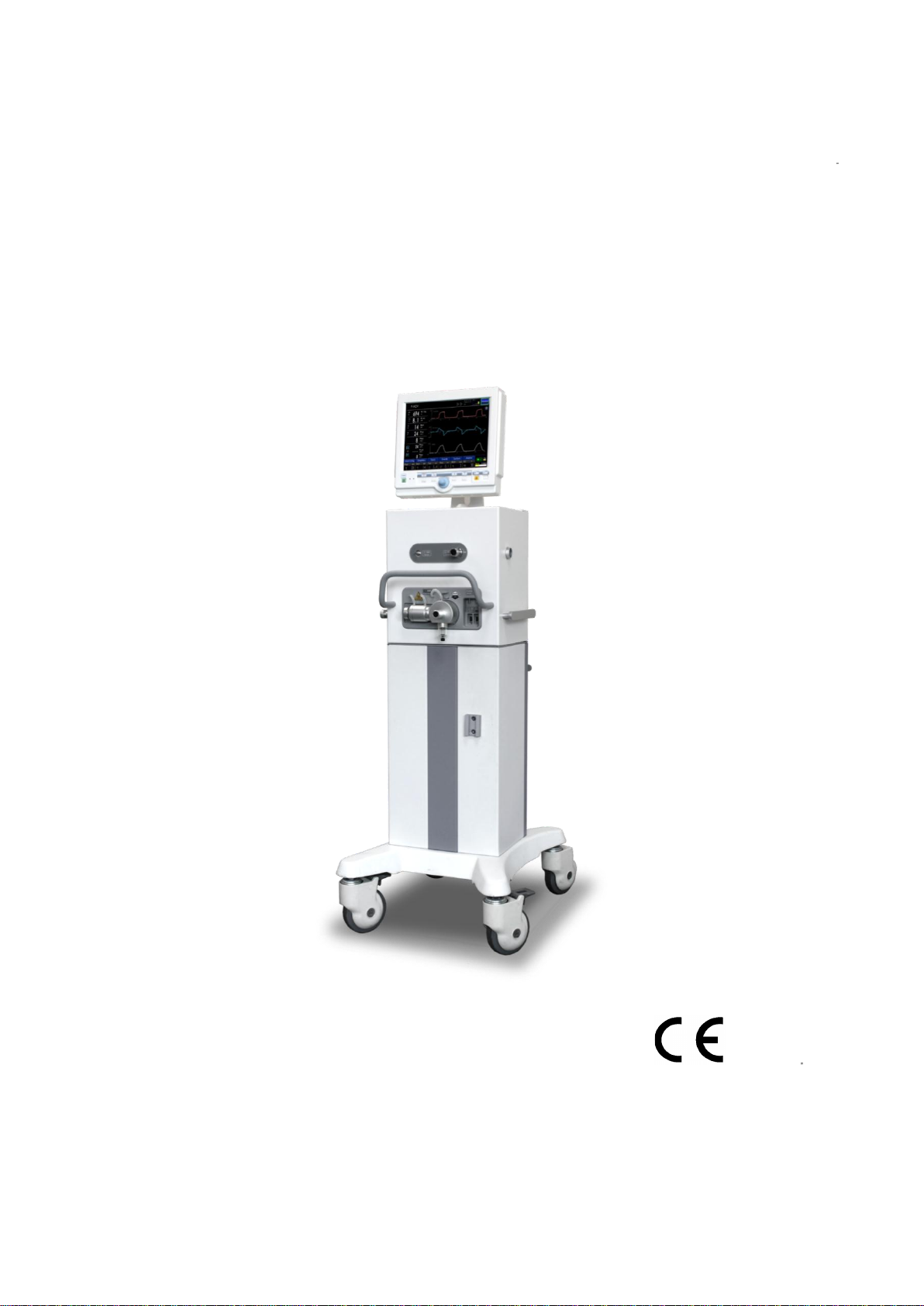
User’s Manual
0470
This User Manual may be revised for the improvement of the product, without prior notification.
Images in this User Manual may differ from the actual product.
MV2000[SU:M] Ventilator System
Eng. Ver. 1.10.0, Apr, 2013
MV2000[SU:M] Ventilator MEKICS Co., Ltd
Page 2
User Manual
This User Manual is provided to users with MV2000[SU:M] Ventilator product.
Since this User Manual is compatible with MV2000[SU:M]
Ventilator, it may not be used with other products
manufactured by our company. In case of loss or damage
in the User Manual, you may refer to MEK-ICS web site for
downloading the manual file.
URL: http://www.mek-ics.com
MV2000[SU:M] User Manual includes precautions and risks
to users prior to use of ventilator. Please read all
precautions for use thoroughly before operating the
product.
Eng. Ver. 1.10.0, Apr, 2013
You may quickly find wanted information using the table of
contents during operation.
If you have any inquiries on details of the product, contact
our company or visit Customer Service Center.
Notice
This document includes exclusive information protected by copyright. The copyright law prohibits
unauthorized copying and modification of the document without prior approval.
Warranty
Contents included in this document may be changed without announcement.
Our company is not responsible for any problems and damages caused from use of performance or data
different from the details of this document.
Revision History
Part and revision numbers in this document represent current version.
The revision number is not changed if subordinate documents are modified or supplemented.
The revision number is only changed in case of change in part numbers or technical matters.
MV2000[SU:M] Ventilator MEKICS Co., Ltd
Page 3

Table of Contents
1. Introduction ....................................................................................................................................................................... 1
1.1 Device Outline .......................................................................................................................................................... 1
1.1.1 Device Illustration ............................................................................................................................................. 1
1.1.2 Device Configuration ....................................................................................................................................... 1
1.1.3 Use ........................................................................................................................................................................... 1
1.1.4 User ......................................................................................................................................................................... 1
1.1.5 Environment ......................................................................................................................................................... 1
1.1.6 Service Guideline ............................................................................................................................................... 1
1.1.7 Exceptions for Legal Responsibilities ....................................................................................................... 1
1.2 Warning, Caution, Important and Reference Matters ........................................................................ 2
1.2.1 Summary ............................................................................................................................................................... 2
1.2.2 Precautions for Storage .................................................................................................................................. 3
1.2.3 Precautions for Use .......................................................................................................................................... 4
1.2.4 Precautions for Electric Safety ..................................................................................................................... 5
1.2.5 Precautions for Electronic Safety ............................................................................................................... 6
2. System Outline ................................................................................................................................................................ 7
2.1 Ventilator Configuration ..................................................................................................................................... 7
2.2 User Interface – Connection, Label, Symbol ............................................................................................ 7
2.2.1 User Interface Configuration ....................................................................................................................... 8
2.2.2 User Interface Diagram .................................................................................................................................. 9
2.2.3 User Interface Symbol .................................................................................................................................. 10
2.3 User Interface Usage ........................................................................................................................................... 10
2.3.1 Touch Screen Setting .................................................................................................................................... 10
2.3.2 Encoder Setting ............................................................................................................................................... 11
2.3.3 Fixed Keys ........................................................................................................................................................... 11
2.3.4 Direct Access Button ..................................................................................................................................... 12
2.3.5 Menu Key ........................................................................................................................................................... 12
2.3.6 Status (System Information Window) .................................................................................................... 13
MV2000[SU:M] Ventilator MEKICS Co., Ltd
Page 4

Table of Contents
2.4 Patient Unit – Connection, Label, Symbol .............................................................................................. 13
2.4.1 Patient Unit Configuration .......................................................................................................................... 13
2.4.3 User Interface Symbol ................................................................................................................................... 14
2.5 Transportation and Storage in Hospitals ................................................................................................ 14
2.5.1 Prior to Transportation ................................................................................................................................. 14
2.5.2 During Transportation ................................................................................................................................... 15
2.5.3 Transportation Between Hospitals........................................................................................................... 15
2.5.4 Storage ................................................................................................................................................................. 15
3. Power Supply ................................................................................................................................................................. 16
3.1 Outline ........................................................................................................................................................................ 16
3.1.1 Power Supply Specification ........................................................................................................................ 16
3.1.2 Battery Information Summary ................................................................................................................... 16
3.2 Battery Status Display Screen ........................................................................................................................ 16
3.3 Alarm and Safety Devices ................................................................................................................................ 17
3.3.1 Warnings ............................................................................................................................................................. 17
3.3.2 AC Power Supply Failure ............................................................................................................................. 17
4. Operation Method ....................................................................................................................................................... 18
4.1 Operation Sequence Summary ...................................................................................................................... 18
4.2 Pre-Use Check ......................................................................................................................................................... 18
4.2.1 Start Up ............................................................................................................................................................... 18
4.2.2 Auto transition Between AC Power and Battery Power ................................................................ 19
4.2.3 Tube Inspection for Patients ...................................................................................................................... 19
4.3 Patient Information Input ................................................................................................................................ 19
4.4 Ventilation Mode and Parameter Setting ............................................................................................... 20
4.5 Alarm Setting .......................................................................................................................................................... 20
4.6 Starting Ventilation .............................................................................................................................................. 20
4.7 Change in Patient Type ..................................................................................................................................... 20
MV2000[SU:M] Ventilator MEKICS Co., Ltd
Page 5

Table of Contents
4.8 Change in Setting Parameter ......................................................................................................................... 21
4.9 Measurement Sensor Calibration ................................................................................................................. 21
4.9.1 Flow Zeroing...................................................................................................................................................... 21
4.9.2 Expiratory Flow Gain ...................................................................................................................................... 21
4.9.3 Adult/Neonatal Proximal Flow Gain ....................................................................................................... 22
4.9.4 O2 Cell Calibration .......................................................................................................................................... 22
4.9.5 Leakage Test ...................................................................................................................................................... 22
4.9.6 EtCO2 Zeroing ................................................................................................................................................... 22
4.10 Separation of Ventilator from Patient .................................................................................................... 22
5. Monitor and Information Saving ..................................................................................................................... 23
5.1 Measurement Value Display ........................................................................................................................... 23
5.1.1 Measurement Value Screen ........................................................................................................................ 23
5.1.2 Additional Measurement Display Screen ............................................................................................. 23
5.1.3 List of Measurement and Calculation Values ..................................................................................... 24
5.2 Waveform Display ................................................................................................................................................ 25
5.2.1 Characteristics ................................................................................................................................................... 25
5.2.2 Waveform Setting and Change ................................................................................................................ 25
5.3 Event Log ................................................................................................................................................................... 27
5.4 Loop ............................................................................................................................................................................. 27
6. Ventilation Mode and Function ........................................................................................................................... 29
6.1 Introduction ............................................................................................................................................................. 29
6.1.1 Warnings ............................................................................................................................................................. 29
6.1.2 Types of Ventilation ....................................................................................................................................... 29
6.1.3 Ventilation Control Method ....................................................................................................................... 30
6.2.1 Volume Control ................................................................................................................................................ 33
6.2.2 Pressure Control .............................................................................................................................................. 33
6.3 Setting Parameter Description ...................................................................................................................... 34
MV2000[SU:M] Ventilator MEKICS Co., Ltd
Page 6

Table of Contents
6.3.1 Trigger Function .............................................................................................................................................. 34
6.3.2 Inspiratory Rise Time ..................................................................................................................................... 34
6.3.3 Respiration Rate ............................................................................................................................................... 35
6.3.4 Apnea Time ........................................................................................................................................................ 35
6.3.5 PEEP ....................................................................................................................................................................... 35
6.3.6 I:E Ratio / Inspiratory Time ......................................................................................................................... 35
6.3.7 Volume Level Setting .................................................................................................................................... 35
6.3.8 Controlled / Supported Pressure Level ................................................................................................. 35
6.3.9 O2 Concentration ............................................................................................................................................. 35
6.3.10 Proximal Sensor On/Off ............................................................................................................................. 35
6.3.11 Mask On/Off ................................................................................................................................................... 36
6.3.12 Previous Mode ............................................................................................................................................... 36
6.4 V-ACV .......................................................................................................................................................................... 36
6.5 P-ACV .......................................................................................................................................................................... 37
6.6 V-SIMV ........................................................................................................................................................................ 39
6.7 P-SIMV ........................................................................................................................................................................ 40
6.8 SPONT ......................................................................................................................................................................... 40
6.9 tBiLEVEL (Spontaneous Ventilation) ........................................................................................................... 41
6.11 O2 Stream ............................................................................................................................................................... 43
6.12 AutoVent ................................................................................................................................................................. 44
6.13 SHFV (Single High Frequency Ventilation) .......................................................................................... 45
6.14 DHFV (Dual High Frequency Ventilation) ............................................................................................. 45
6.15 TCPL-AC ................................................................................................................................................................... 46
6.16 TCPL-SIMV ............................................................................................................................................................. 47
6.17 Ventilation Parameter Outline .................................................................................................................... 47
7. Alarm................................................................................................................................................................................... 49
7.1 Introduction ............................................................................................................................................................. 49
MV2000[SU:M] Ventilator MEKICS Co., Ltd
Page 7

Table of Contents
7.2 Alarm Removal ....................................................................................................................................................... 49
7.2.3 Pausing Alarm Sound .................................................................................................................................... 50
7.2.4 Alarm Sound Volume Control ................................................................................................................... 50
7.3 Alarm Setting .......................................................................................................................................................... 51
7.3.1 Alarm Screen Display..................................................................................................................................... 51
7.3.2 Alarm Setting .................................................................................................................................................... 51
8. Alarm Message .......................................................................................................................................................... 52
8.1 Introduction ............................................................................................................................................................. 52
8.2 Alarm and Error Message................................................................................................................................. 53
9. Supplementary Devices ............................................................................................................................................ 56
9.1 MEKICS Humidifier VH-2600 .......................................................................................................................... 56
9.2 EtCO2 (Option) ........................................................................................................................................................ 56
9.2.1 EtCO2 Connection Method ......................................................................................................................... 56
9.2.2 EtCO2 Calibration ............................................................................................................................................. 57
9.3 SpO2 (Option) .......................................................................................................................................................... 57
10. Initial Screen Configuration ................................................................................................................................. 59
10.1 Introduction .......................................................................................................................................................... 59
10.2 Start-Up Configuration ................................................................................................................................... 59
10.3 System Setting ..................................................................................................................................................... 60
10.3.1 Setup .................................................................................................................................................................. 60
10.3.2 Patient ................................................................................................................................................................ 61
10.3.3 Date .................................................................................................................................................................... 61
10.3.4 Calibration ........................................................................................................................................................ 62
11. Technical Specification ........................................................................................................................................... 63
11.1 System ...................................................................................................................................................................... 63
11.1.1 General .............................................................................................................................................................. 63
11.1.2 Operating Conditions ................................................................................................................................. 63
MV2000[SU:M] Ventilator MEKICS Co., Ltd
Page 8

Table of Contents
11.1.3 Non-operating Conditions ....................................................................................................................... 63
11.1.4 Power Supply .................................................................................................................................................. 63
11.2 Ventilator ................................................................................................................................................................ 63
11.2.1 General .............................................................................................................................................................. 63
11.2.2 Gas Supply ....................................................................................................................................................... 63
11.2.3 Patient System Connectors ...................................................................................................................... 64
11.3 Alarms....................................................................................................................................................................... 64
11.4 Ventilation Modes ............................................................................................................................................. 64
11.4.1 Controlled Ventilation ................................................................................................................................ 64
11.4.2 Supported Ventilation ................................................................................................................................ 65
11.4.3 Combined Ventilation ................................................................................................................................. 65
11.5 Communication / Interface ........................................................................................................................... 65
11.6 Service ...................................................................................................................................................................... 65
11.7 Accessories ............................................................................................................................................................. 65
11.8 Setting Parameter .............................................................................................................................................. 68
12. Summary of Screen Usage ................................................................................................................................... 70
12.1 Fixed Keys .............................................................................................................................................................. 70
12.2 Special Function Keys ...................................................................................................................................... 71
12.3 Menu Keys ............................................................................................................................................................. 72
12.4 Screen Touch Pads ............................................................................................................................................ 73
13. MV2000[SU:M] Series Features ......................................................................................................................... 74
Appendix 1. Introduction .............................................................................................................................................. 75
Appendix 2. Cleaning / Sterilization ....................................................................................................................... 77
Appendix 2.1. Summary of Cleaning / Sterilization Process ................................................................ 77
Appendix 2.2. Preparation / Disassembly ....................................................................................................... 77
Appendix 2.2.1 Preparation ................................................................................................................................... 77
Appendix 2.2.2 Expiratory Cassette Separation ............................................................................................ 77
MV2000[SU:M] Ventilator MEKICS Co., Ltd
Page 9

Table of Contents
Appendix 2.3. Wiping / Disposal ......................................................................................................................... 78
Appendix 2.3.1. Wiping ............................................................................................................................................ 78
Appendix 2.3.2 Disposal .......................................................................................................................................... 78
Appendix 2.3.3. Cleaning Before Sterilization ................................................................................................ 78
Appendix 2.4 Sterilization Process ...................................................................................................................... 79
Appendix 2.4.1 Cleaning Sterilizer ...................................................................................................................... 79
Appendix 2.4.2 Disinfectant ................................................................................................................................... 79
Appendix 2.4.3 Rinsing After Sterilization ....................................................................................................... 79
Appendix 2.4.4 Drying Method ............................................................................................................................ 79
Appendix 2.5 Assembly ............................................................................................................................................. 80
Appendix 2.6 EtCO2 Module Cleaning / Sterilization ............................................................................... 80
Appendix 2.6.1 Preparation ................................................................................................................................... 80
Appendix 2.6.2 EtCO2 Module Body .................................................................................................................. 80
Appendix 2.6.3 Airway Adapter ........................................................................................................................... 81
Appendix 2.7. Accessories ........................................................................................................................................ 81
Appendix 3. Maintenance ............................................................................................................................................. 82
Appendix 3.1. Preventive Maintenance ............................................................................................................ 82
Appendix 3.2. Battery Replacement ................................................................................................................... 82
Appendix 3.3. Accessories ........................................................................................................................................ 82
Appendix 3.4. Warranty Period ............................................................................................................................. 83
MV2000[SU:M] Ventilator MEKICS Co., Ltd
Page 10
1. Introduction
CAUTION
- Regular Inspection
MV2000[SU:M] ventilator must be
regularly inspected by a trained
professional.
- Inspection Record
All matters related to inspection of
MV2000[SU:M] ventilator shall be
recorded in accordance to regulations
by hospital, local government, and
national government.
① ② ①
②
1. Introduction
1.1 Device Outline
This chapter provides guidelines for correct use of
the product and summarized information on the
MV2000[SU:M] ventilator system.
1.1.1 Device Illustration
- Medical professionals
- Individuals who received training on the use of
this device
- Individuals who have experience in treatment
of respiratory diseases
1.1.5 Environment
MV2000[SU:M] ventilator must be used in the
following environments.
- Hospitals
- Facilities and institutions with the purpose of
providing medical service
- Transportation of patients within hospitals or
medical institutions
1.1.6 Service Guideline
1.1.2 Device Configuration
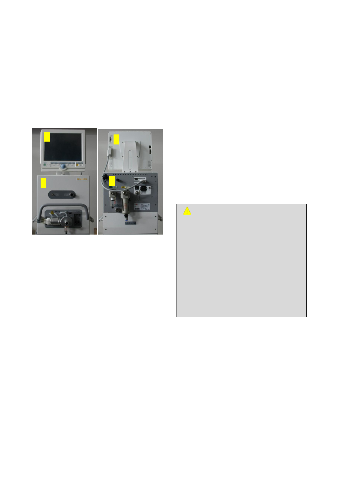
MV2000[SU:M] ventilator is composed of the
following.
1) User Interface
- Configures ventilation mode and displays
patient measurement data with alarms
2) Main
- Mixes supplied gas
- Delivers and exchanges gas
1.1.3 Use
MV2000[SU:M] ventilator is a device designed to
treat and monitor insufficient ventilation or
patients suffering respiratory insufficiency.
1.1.4 User
MV2000[SU:M] ventilator must be used by the
following users.
MV2000[SU:M] Ventilator MEKICS Co., Ltd
1.1.7 Exceptions for Legal
Responsibilities
- Inappropriate environment
Our company is not responsible for safe
operation of MV2000[SU:M] ventilator if
environment described in this Manual is not
followed.
- Service by a non-professional
If this product is serviced or repaired by an
individual who did not complete relevant
1
Page 11

1. Introduction
WARNING
- Always perform pre-checking prior to
connecting the ventilator to a patient.
- In case of the following, stop the use of
ventilator and contact service assistant.
→ If unordinary screen shows up
→ If an alarm cannot be settled
→ If the device creates abnormal sound
→ If the device is operating abnormally or
shows unexpected failure
- The ventilator must always be maintained
vertical during use.
- If the ventilator is connected to a patient,
→ Carefully monitor the patient.
→ Prepare for reserve ventilators for easier
use.
→ Do not raise or separate expiratory part.
→ Always check setting and measurement
values displayed on the screen.
- MV2000[SU:M] ventilator must be
operated by an experienced user in
accordance to guidelines given in this
booklet.
- Do not cover the ventilator in any way.
This may cause errors in its functions.
- Expiratory part of the ventilator and
expiratory may be contaminated.
training, our company is not responsible for safe
operation of MV2000[SU:M].
1.2 Warning, Caution, Important and
Reference Matters
Symbols are indicated on the interior and exterior
of the product and in this User Manual.
The symbols represent important cautions and
advice to the user. Please read the following
symbols carefully and be well informed of them
for the use and storage of the product. .
DANGER
This symbol represents “DANGER.”
It is associated with possible matters that may
environment or additional references to the
descriptions in this manual. It does not
pertain to possible damages to the product or
the patient.
1.2.1 Summary
This booklet summarizes functions and
characteristics of the MV2000[SU:M] ventilator
system. Since not all details of MV2000[SU:M] are
included in this booklet, do not use this booklet
as a document for training.
greatly harm the product or the patient, or
might even cause the patient’s death.
WARNING
This symbol represents “WARNING.”
It is associated with possible matters that may
harm or cause irreversible damage to the
product or the patient..
CAUTION
This symbol represents “CAUTION.”
It is associated with possible matters that may
damage the product or harm the patient.
ATTENTION
This symbol is associated with safety issues
that the user should give attention to and be
well informed of before using the product.
How to use the product is described in each
section of this manual
NOTE
This symbol is associated with issues you
should note regarding the surrounding
MV2000[SU:M] Ventilator MEKICS Co., Ltd
2
Page 12
WARNING
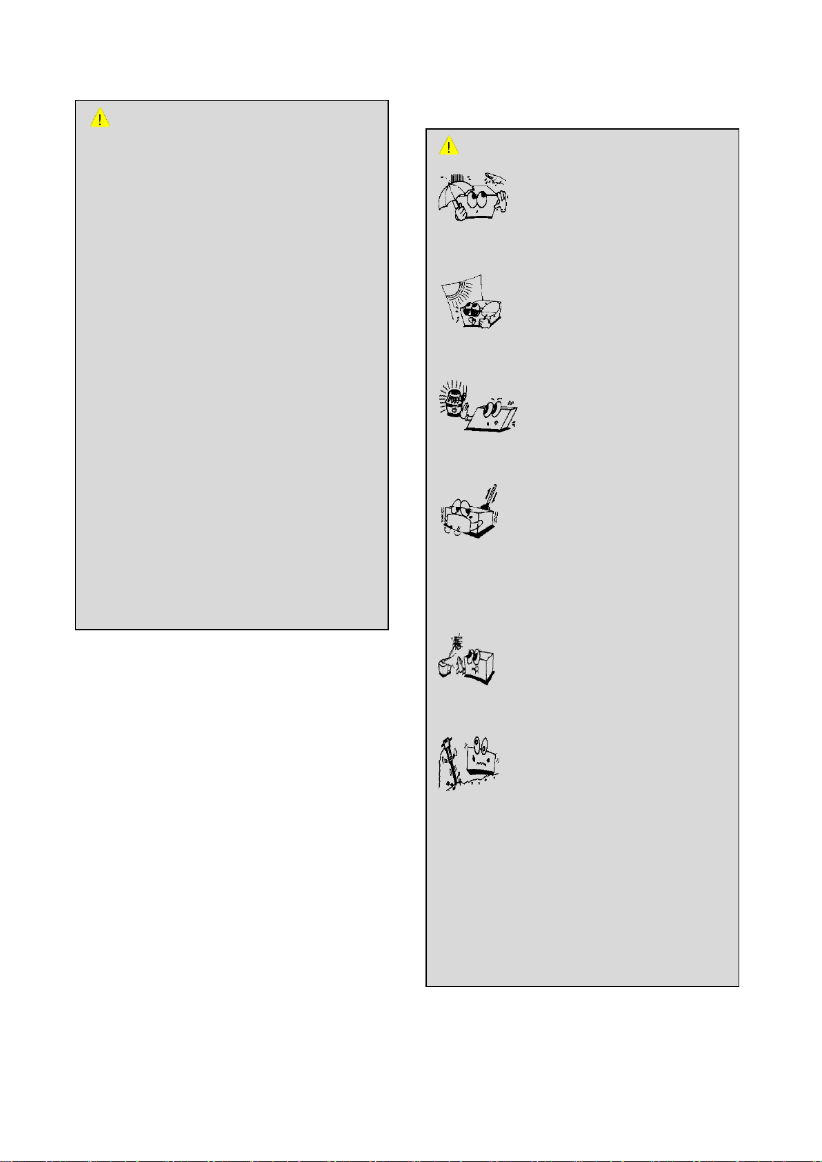
1) Do not store the product in a place
exposed to humidity..
2) Do not store the product in a place
exposed to directsunlight.
3) Do not store the product in a place near a
heating device.
4) Do not store the product in a place with
extreme thermal variation.
(Proper Temperature range is -15℃ ~ 50℃ and
humidity range is 10% ~ 90%)
5) Do not store the product in a very humid
place or in a place with poor ventilation.
6) Do not install or place the product where it
may fall or be dropped.
Do not store the product in a place that may
cause the patient any harm.
Do not store the product in a place where the
product could be exposed to extreme impact
or vibration.
CAUTION
- Device for prevention of dry lung
tissues, such as disposable humidifier
or humidifier, must always be used.
- Refer to installation guideline for
ventilator system and options for
accurate assembly.
- When separating or transporting the
ventilator or its parts, refer to User
Manual or request our company. Always
take care in transportation.
- Be careful when handling tube,
connector, and patient tube parts. Use
of support arm can reduce weight of
tube inflicted on the patient.
- Do not renovate or remove any part of
the ventilator.
- If the product is repaired after not
following the uses described in this
booklet, our company is not responsible
for safe operation of ventilator
MV2000[SU:M].
1. Introduction
1.2.2 Cautions for Storage
MV2000[SU:M] Ventilator MEKICS Co., Ltd
3
Page 13
WARNING
1) This product is extremely dangerous
when used or stored in places exposed
to chemical substances or explosive
gases.
2) Battery may explode when using the
product under flame or high
temperature.
3) Do not disassemble or dismantle the
product. Our company will not take any
responsibility on disassembled products.
4) Read this manual prior to use and
check settings for various sensors and
devices. This product should only be
used by an authorized individual with
sufficient knowledge about patient
monitoring devices.
5) The product must be verified regularly
to check for accurate operation.
6) Do not use one product on two patients
simultaneously.
7) Do not use in places exposed to
humidity.
8) It is extremely dangerous to use the
product with wet hands.
9) Do not use the product under direct
sunlight.
10) Do not use the product in places with
large temperature fluctuations.
Temperature range is 10C ~ 40C and
humidity range is 10% ~ 90%.
7) Do not store the product in a place where
the product could be exposed to chemicals
or explosive gases.
8) Be careful to prevent dirt, especially metal
materials, from getting inside the product.
9) If the product dysfunctions, do not
disassemble the product yourself.
Only MEKICS’ service personnel and
designated service technicians are
authorized to disassemble the product for
repair or battery replacement. If you
disassemble the product yourself, you will
not receive any service for the product.
10) Turn off the product when you will not
be using the product for a while.
1. Introduction
1.2.3 Cautions for Use
MV2000[SU:M] Ventilator MEKICS Co., Ltd
4
Page 14

1. Introduction
WARNING
1) The rated power input for this product
is AC 100~240V / 10A / 50–60Hz.
2) Connect the power plug to an AC
power outlet with an earth terminal.
3) Note that neither the company nor any
representative of the company will be
responsible for any issues arising from
the use of any power source out of the
rated power input.
4) Only authorized personnel who are
trained to service the product may
disassemble the product. Note that
neither the company nor any
representative of the company will be
responsible for any electric shock,
short circuit or product damage caused
by unauthorized disassembly. Failure to
comply will cancel the product
warranty and make the product
ineligible for service.
CAUTION
1) This product is used to determine
patient status. Other clinical
information must be used together for
accurate diagnosis.
2) Take care not to cause pain on patients
from tightening of sensors. Also, take
care not to tangle patients with sensor
cables.
3) If measurement values displayed on
the screen are considered inaccurate,
measure another patient for
comparison.
11) Do not use the product nearby electric
heating devices.
12) Do not use the product under high
humidity or ventilation problem.
13) Do not use the product in places with
excessive impact or vibrations.
14) Take care to prevent dusts, especially
metal substances from entering the
product.
1.2.4 Precautions for Electric Safety
MV2000[SU:M] Ventilator MEKICS Co., Ltd
5
Page 15

1. Introduction
WARNING
1) A strong electromagnetic wave may
affect the performance of the product.
2) Basically, the product is designed to
not suffer functional disorders by
surrounding electromagnetic waves.
Notwithstanding, strong electromagne
-tic waves may cause the product to
malfunction. This may include
displaying incorrect calculation values,
disappearance of measurements and
noises affecting the wave pattern. If
such errors continue, contact the
MEKICS Technical Service Center or
authorized dealers for assistance
3) If used by a patient with pace maker, a
professional individual with all required
expert knowledge must operate the
product.
4) Electromagnetic waves generated from
an MRI device may influence the
measurement values of the product.
ATTENTION
1) This product uses 12V / 7Ah lead (Pb)
battery.
2) When charging battery, connect the AC
cable. Take care to prevent metal
substances from contacting the battery
charging terminal.
CAUTION
1) Only use auxiliary equipment provided
by the MEKICS Head Office or MEKICS’
designated representatives.
5) If the power cord or sensor cable is
damaged, immediately stop using the
product and replace the power cord or
cable. Using the product when the
power cord or sensor cable is damaged
may cause an electric shock, short
circuit, current leakage or product
damage.
6) Do not bump or move the product
while the power cord or sensor cable is
connected to it. This may cause patient
injuries or product malfunctions.
7) When using the product with other
devices, use a separate AC power
source for the other devices to ensure
the patient’s safety.
8) Do not use an anti-electrostatic or
conductive tube for the product.
9) Auxiliary equipment and accessories
provided by MEKICS are qualified items
that meet electrical safety standards.
The use of other companies’ products
or unproven items may cause injury to
the patient or product damage.
1.2.5 Precautions for Electronic Safety
This product acquired electronic safety standard,
CLASS II-A.
MV2000[SU:M] Ventilator MEKICS Co., Ltd
6
Page 16
2. System Outline
CAUTION
When not moving the ventilator, wheels must be
fixated using lock.
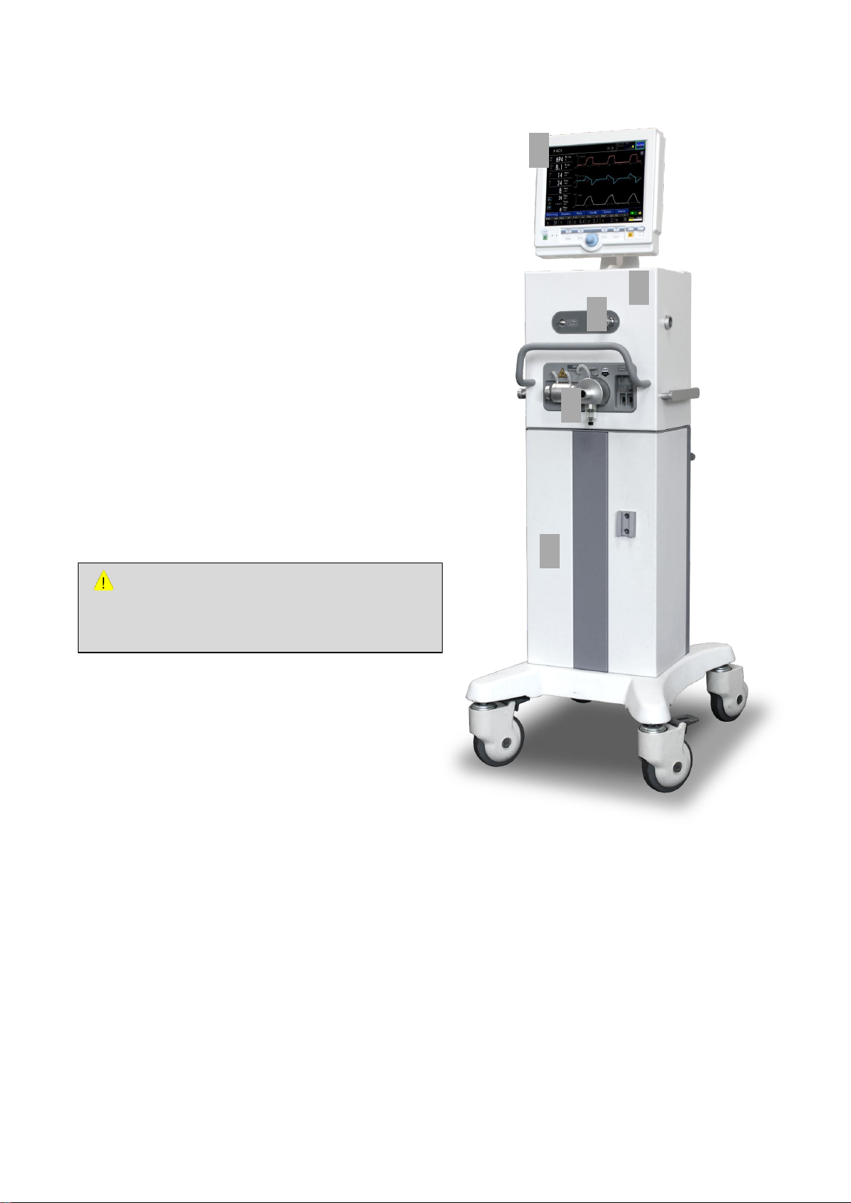
①
②
③
④
⑤
2. System Outline
2.1 Ventilator Configuration
Setting values of the ventilator can be configured
using touch pad, key, or encoder.
Parameters related to ventilation are always
measured and can be adjusted. Gas supply can be
controlled to obtain objective values (flow, volume
and pressure) through difference between actually
measured parameters and setting or calculated
values.
MV2000[SU:M] ventilator has two gas modules (O2,
air). Gas can be supplied through hospital’s
medical gas supply system or compressor and gas
container.
In order to prevent movement of the ventilator
from carelessness, check whether the ventilator is
fixated to the correct position on the cart.
1) User Interface (Screen)
2) Patient Unit (Main Body)
3) Mobile Cart
4) Inspiration Outlet
5) Expiration Inlet
MV2000[SU:M] Ventilator MEKICS Co., Ltd
2.2 User Interface – Connection, Label,
Symbol
7
Page 17

2. System Outline
User interface is composed of the following.
- Touch Screen
- Fixed Keys
- Encoder (Rotational Dial)
2.2.1 User Interface Configuration
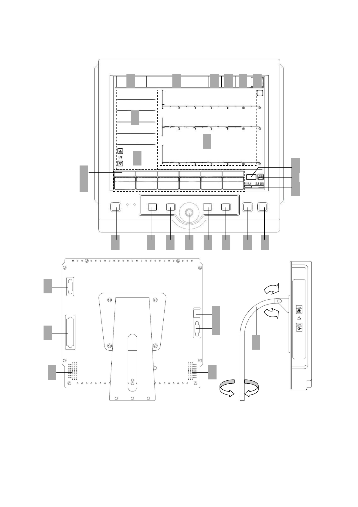
Refer to the user interface diagram on the next
page to check for location of the following.
1) Display of current ventilation mode
2) Alarm display and alarm message window
3) Status icon
4) Date, time, O
5) Nebulizer On/Off display
6) Ventilation mode setting
7) Measurement value display
8) Pad to view diverse measurement values
9) Waveform window
100% display
2
Execute or run operation
21) Alarm silence
Alarm does not make sound for 2 minutes.
22) Alarm reset
Reset alarms.
23) External VGA out port
An external monitor can be connected for
larger screen or additional screen.
24) LAN port
RJ45 cable is used to communicate with
external devices.
25) Connector between screen and main body
Connector connects the screen from main
body using cable.
26) RS232 serial port
Serial port is used for DSC software upgrade
and communication with COM.
27) Speaker
28) Screen panel support
10) Three parameter waveforms, pressure/flow,
and flow/volume loop display
11) Various menu to operate ventilator
MV2000[SU:M]
12) Pad to add or change setting values
13) Power supply (AC - green, BATT – orange)
Touch key lock/unlock
14) I:E graph
15) System On/Off switch
Standby key is used during operation of the
product. Standby state is a state in which all
things except the ventilator are turned on.
16) Manual inspiration
17) O
100%
2
18) Encoder
Encoder is used to select menu or parameter.
Also, encoder is used to adjust values and
save adjusted values by clicking.
19) Exit (Cancel button)
20) Run (Accept)
MV2000[SU:M] Ventilator MEKICS Co., Ltd
8
Page 18
2.2.2 User Interface Diagram
① ② ③ ④ ④ ⑤ ⑥ ⑦ ⑧ ⑨ ⑩
⑪ ⑫ ⑬ ⑭ ⑮
○16
○17
○18
○19
○20
○21
○22
○27
○27
○25
○23
○24
○26
○28
2. System Outline
9
MV2000[SU:M] Ventilator MEKICS Co., Ltd
Page 19
2. System Outline
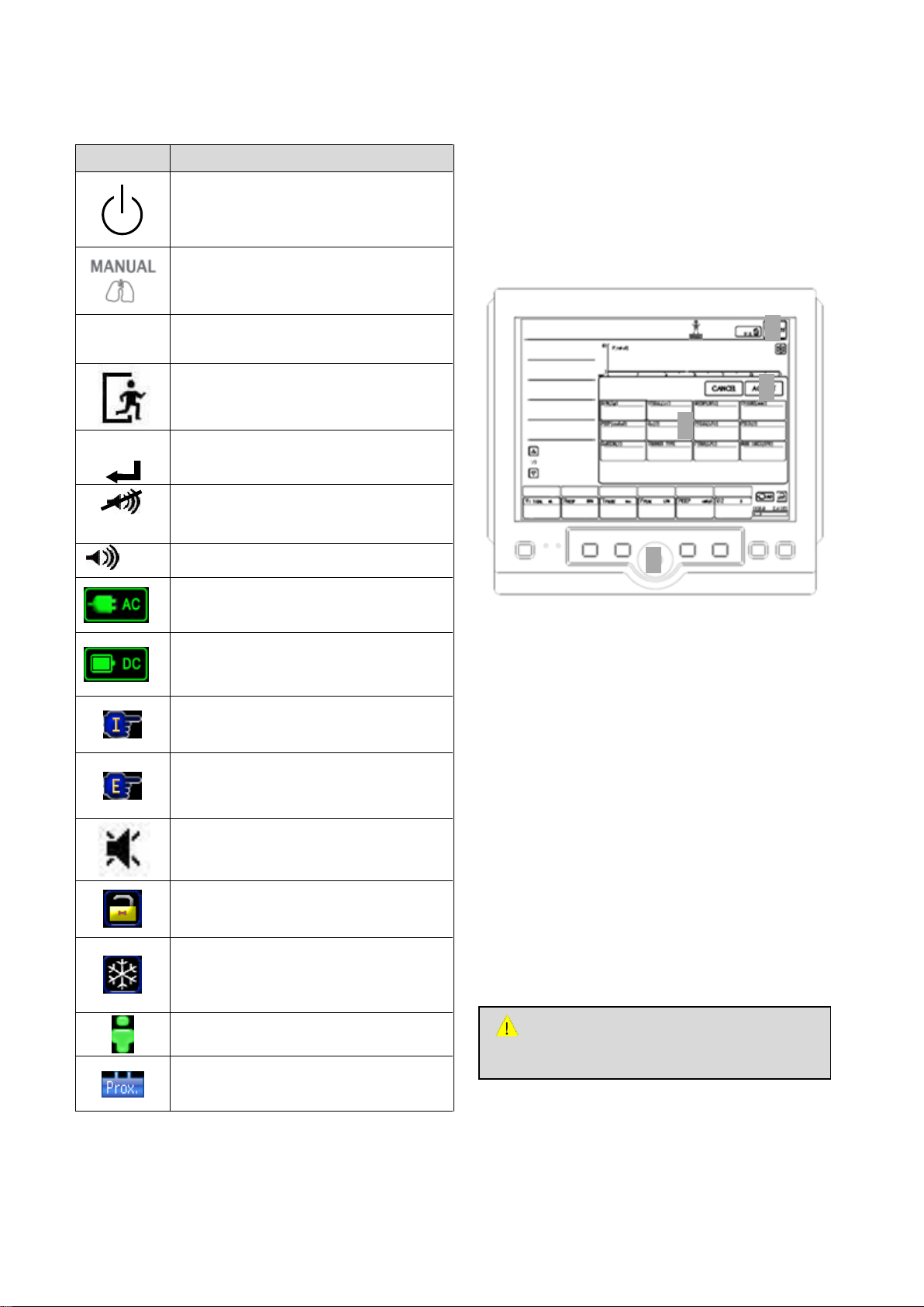
Symbol
Description
On/Off Switch, Standby – Transition to
standby state or display of ventilator
on/off state
IEC417-5009
Manual Inspiration Key – Inspiration is
applied to the patient every time Manual
Inspiration Key is pushed.
O
2
100%
100% O2 Mode – Displays 100% O2
mode. Turned on/off using O2 100% key.
EXIT Key – Removes menu window from
the screen.
RUN
RUN Key – Used to run the ventilator
using values in ventilator set.
2MIN
Alarm 2MIN – Mutes auditory alarm
signal for two minutes.
RESET
Alarm RESET – Resets existing alarms.
AC Power – Displays that the device is
operating under AC power.
Battery check – Displays that the device
is operating with battery, as well as
remaining battery state.
Inspiration Hold – Measures compliance
and resistance by adding one second to
inspiration hold time.
Expiration Hold – Auto PEEP is measured
after maintaining expiration hold for two
seconds.
Alarm Sound Off or Mute – Displays
alarm sound off or mute. This can be
turned on/off using 2MIN key.
Touch Key Lock – Keys on the touch
screen are locked by pushing key lock.
They are unlocked by pushing again.
Freeze – Freezes currently displayed
graph. In case of trend screen,
encoder can be used to view saved
trend values.
Adult – Displays male, female,
pediatric and neonate mode.
Proximal – Displays whether a
proximal sensor is connected.
ATTENTION
Do not use sharp tools to use touch screen.
①
②
③
④
2.2.3 User Interface Symbol
2.3 User Interface Usage
The following is the general method of using user
interface, according to the sequence.
2.3.1 Touch Screen Setting
Ventilator Setting Method:
1) Open ventilation mode setting window by
pushing ventilator mode (Modes) on top of
the screen.
2) Push the parameter to configure and activate
it. Once activated, Blue frame is turned white,
and values can then be changed.
3) Rotate the encoder to find wanted value. Push
the encoder again or touch activated
parameter window again in order to settle
adjusted value. When parameter turns blue,
new setting has been saved.
4) Push Accept to operate new setting values
and Cancel to cancel.
MV2000[SU:M] Ventilator MEKICS Co., Ltd
10
Page 20
2. System Outline
ATTENTION
When using special vent function, user must
always monitor the patient carefully.
①
②
③
④ ⑤ ⑥ ⑦ ⑧
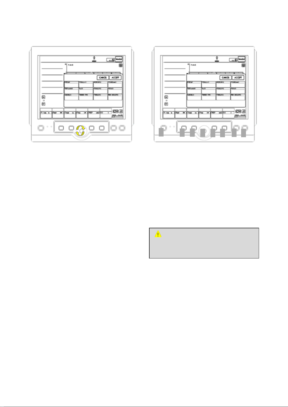
2.3.2 Encoder Setting
Ventilator Setting Using Encoder
1) Rotate the encoder to find wanted menu.
2) Select by push the encoder. Once activated,
Blue frame is turned white, and values can
then be changed.
2.3.3 Fixed Keys
User interface has the following fixed keys.
1) On/Off Switch, Standby
2) Manual Inspiration
3) O
4) Encoder
100%
2
3) Rotate the encoder to find wanted value.
4) Push the encoder again or touch activated
parameter window again in order to settle
adjusted value.
5) When parameter turns blue, new setting has
been saved.
6) Push Accept to operate new setting values
and Cancel to cancel.
5) Exit
6) Run
7) Alarm Silence (2min)
8) Alarm Reset
MV2000[SU:M] Ventilator MEKICS Co., Ltd
11
Page 21
2. System Outline
NOTE
When parameters are changed using direct
access button, changed values are applied
since the next breath. Here, there is no
button to confirm user’s intentions such as
Accept button on touch screen.
① ② ③ ④ ⑤
⑥
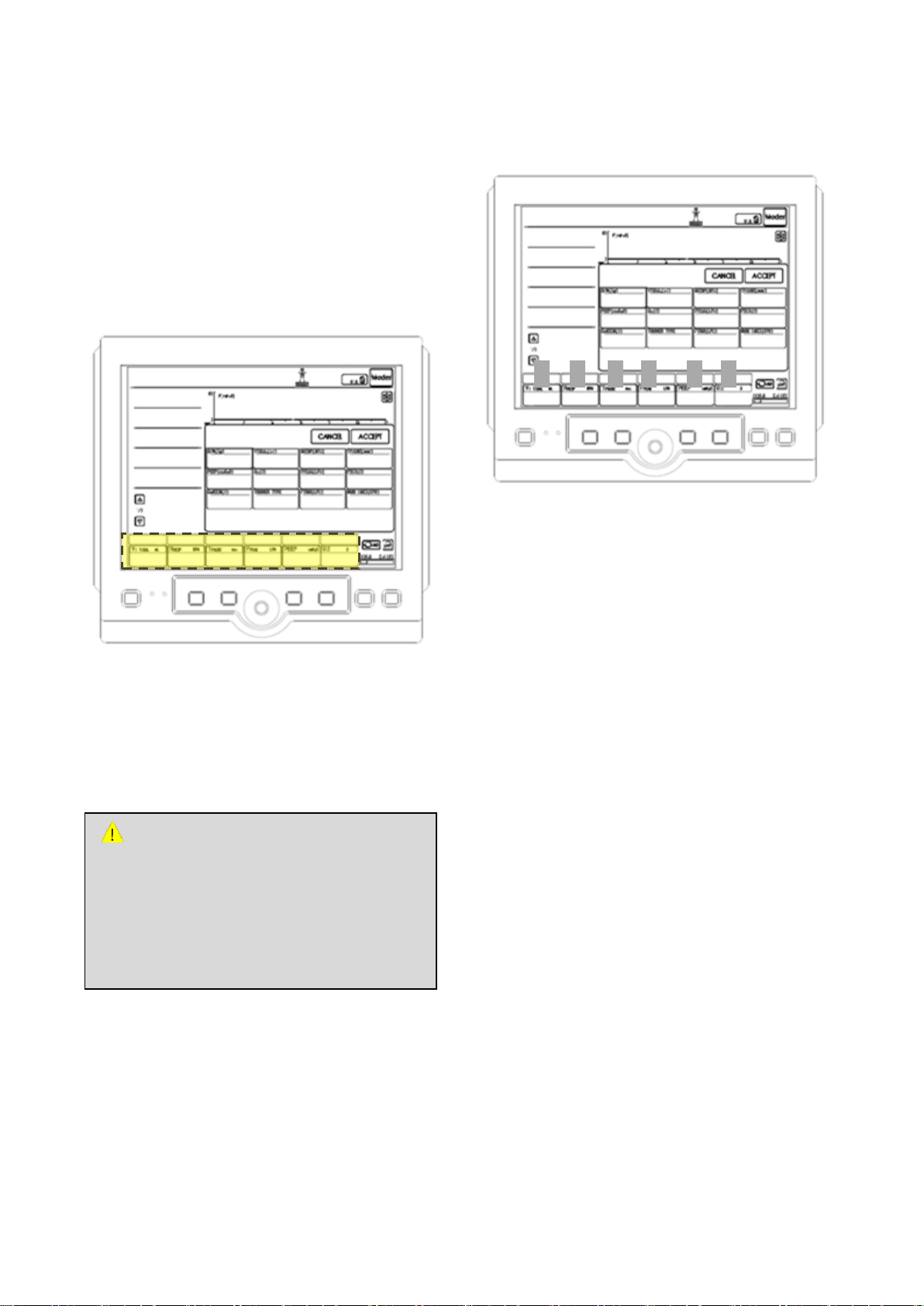
2.3.4 Direct Access Button
Bottom of user interface has direct access buttons
that can directly adjust 6 setting parameters.
Parameter corresponding to each button is
automatically selected based on ventilation mode.
Direct Access Button Use
2.3.5 Menu Key
6 menu keys are positioned on the bottom of user
interface. These keys can be touched for activation.
In order to adjust ventilation mode parameter,
1) Activate by touching the wanted direct access
button.
2) Use the encoder to configure values.
3) Touch again to deactivate.
Description on each menu is as follows.
1) Monitoring – Comprehensively displays data
measured in each mode.
2) Graphic – Configures screen layout and trend
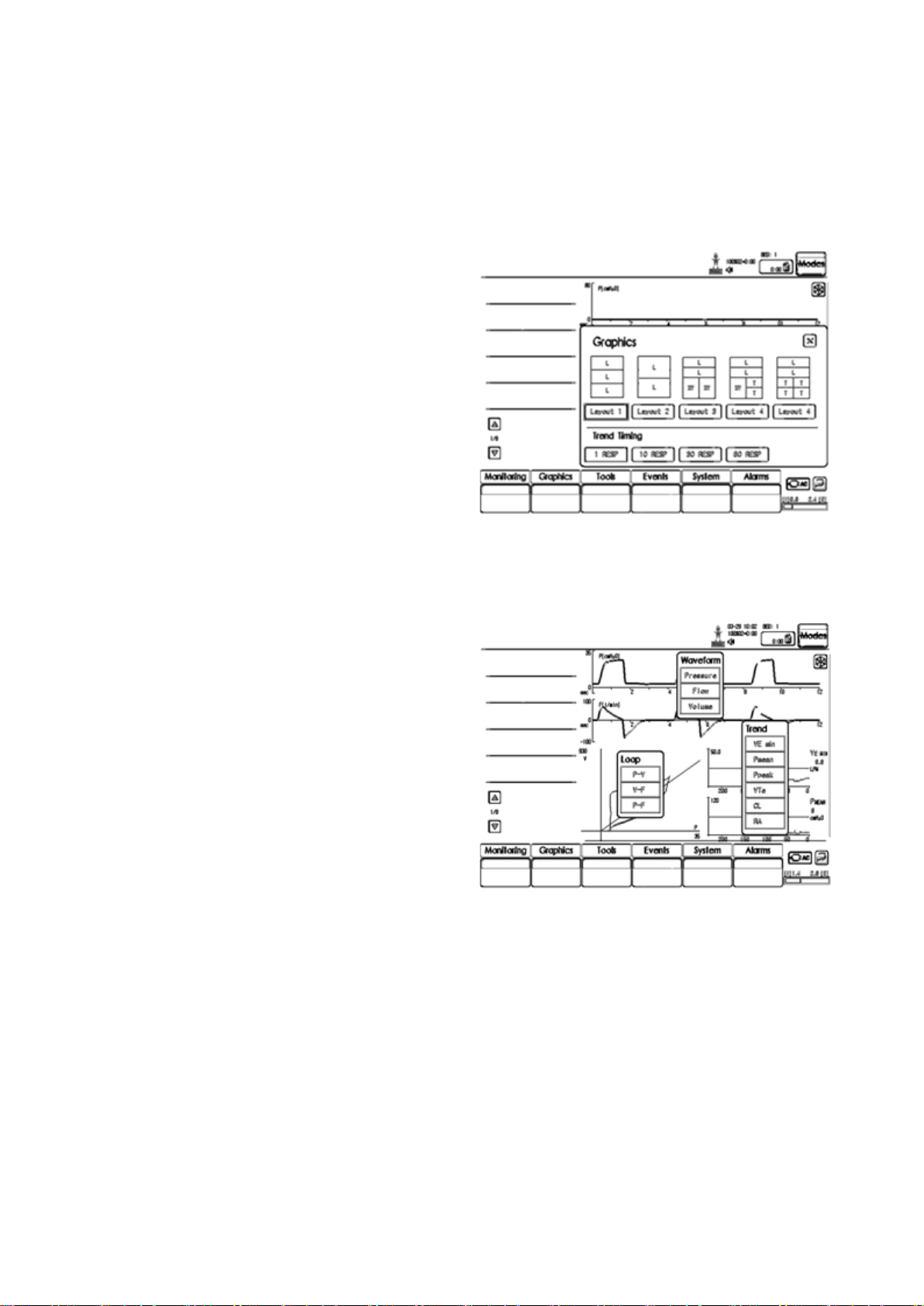
timing (Waveform – Pressure, Flow, Volume /
Loop – P-V, V-F, P-F / Trend – VE MIN, PMEAN,
PPEAK, VTE, CL, RA).
3) Tools – Uses Insp.Hold and Exp.Hold functions.
4) Events – Events that occur during operation of
the ventilator can be seen.
5) System – Composed of operating environment,
patient information input, date change, and
various calibration settings.
6) Alarms – This menu is used to configure
various alarms on measurement values.
MV2000[SU:M] Ventilator MEKICS Co., Ltd
12
Page 22
2. System Outline
CAUTION
When external 12V DC power is used, insert
internal battery for safe and normal
operation.
① ② ③ ④ ⑤
⑥
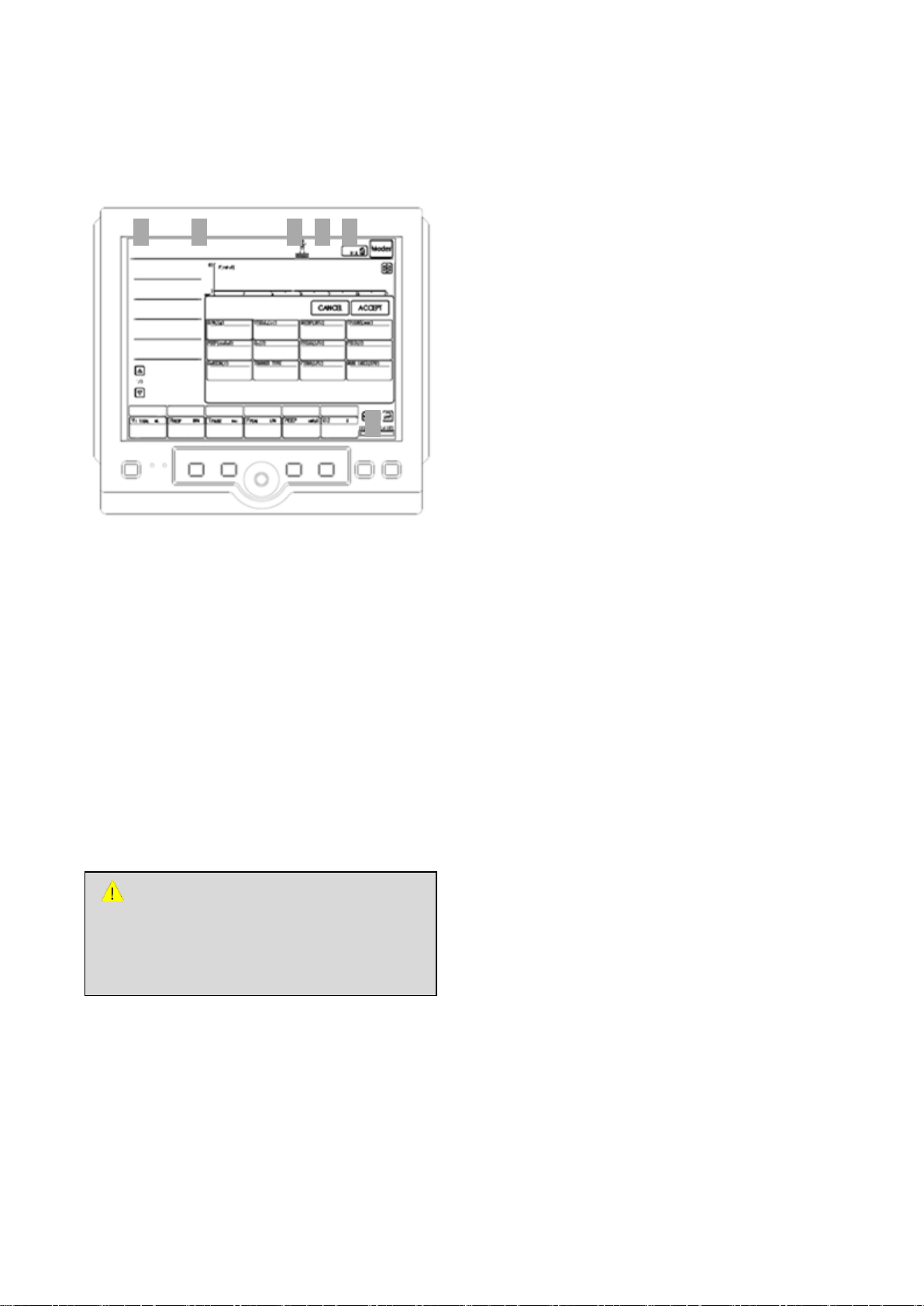
2.3.6 Status (System Information
Window)
User interface displays current status of the
ventilator.
Types of status displayed are as follows.
1) Current ventilation mode display
2) Alarm display and alarm message window
3) Ins, Exp hold, Adult & Proximal sensor Icon
4) Date, time and O
5) Nebulizer On/Off display
6) Power supply (AC - green, BATTERY – orange)
Touch key lock/unlock
I:E graph
100% display
2
2.4 Patient Unit – Connection, Label,
Symbol
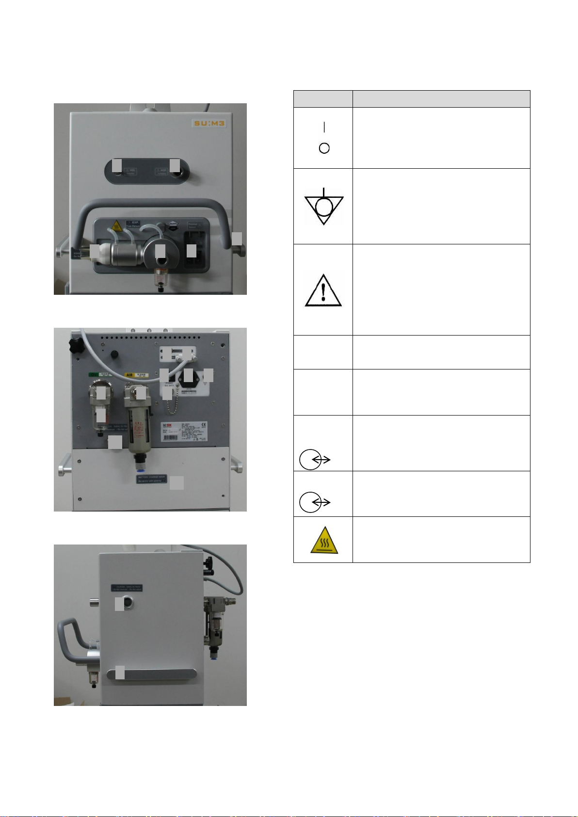
Patient unit (main body of the ventilator) is
composed of the following parts.
- Gas supply and connection part
- Power supply and connection part
- Accessory connection part
2.4.1 Patient Unit Configuration
Refer to the patient unit diagram on the next
page to check for location of the following parts.
A
A1. Nebulizer Port
A2. Inspiration Outlet
A3. Expiration Outlet
A4. Expiration Inlet
A5. Handle for Moving
A6. SpO2, EtCO2 Connector
B
B1. External Battery Port
B2. Main Power Switch
B3. AC Power Inlet
B4. Ground Terminal
B5. O2 Gas Inlet
MV2000[SU:M] Ventilator MEKICS Co., Ltd
B6. Air Gas Inlet
B7. Water Trap
B8. Connector between Screen and Main Body
B9. RS232 Communication Terminal
B10. Tank Safety Air Relief
B11. Battery Cover
C
C1. Safety Air Relief
C2. Body Handle
13
Page 23
2. System Outline
Symbol
Description
Power On/Off – These symbols are used
in power switch. “I” indicates power on.
“O” indicates power off.
IEC 601-1
Equipotentiality – This symbol indicates
terminal that does not require ground
potential for connecting system parts to
create equipotentiality.
IEC601-1, IEC 417-5021
Attention, Consult accompanying
documents
This symbol indicates that user must
consult accompanying document (User
Manual) prior to operation.
IEC 601-1
EXT.
BATT
EXT. BATT – This symbol indicates
external battery for vehicles.
AC IN
This symbol indicates external power (AC)
connection part.
IEC 417-5534Pr
TO
Monitor
Monitor Connector – This symbol
indicates connection to user interface
and cable.
RS232
RS232 / Serial Port – This symbol
indicates data communication
connection.
Heater – Heater heats the exp part
during ventilation to prevent moisture. Be
careful about high temperature heat.
A2
A1
A4
A5
A6
A3
B6
B11
B10
B7
B5
B2
B3
B4
B1
B8
B9
C1
C2
A
B
2.4.3 User Interface Symbol
C
MV2000[SU:M] Ventilator MEKICS Co., Ltd
2.5 Transportation and Storage in
Hospitals
2.5.1 Prior to Transportation
Check the following matters before transporting
the ventilator whether, the ventilator is connected
to a patient, or not
14
Page 24

2. System Outline
- Check whether patient unit and user interface
are firmly fixed and locked.
- Check whether accessories such as modules
and humidifier are firmly fixed.
- Check the connection of gas container and
amount of gas in the container.
- Check whether battery is sufficiently charged.
- Check whether the ventilator operates
properly.
- Check for damages in the mobile cart.
- If medical portable compressor MC200 is
used, make sure it is firmly fixed to prevent
movement during transportation.
2.5.2 During Transportation
Check the following matters before transporting
- When storing ventilator, always connect to
main power source for battery to be charged
sufficiently.
- Do not discard battery and O2 cell with
ordinary wastes.
- Do not expose the ventilator to a temperature
below -15℃ (-5℉) or above +50℃ (+122℉).
- Do not expose the ventilator to a relative
humidity above 90%.
the ventilator whether, the ventilator is connected
to a patient, or not
- Use the handle on the main body.
- Move slowly the bed and ventilator. During
transportation, be careful about pulling or
movement of tubes connected to the patient.
- When moving or changing location of
support arm, be careful about pulling or
movement of tubes connected to the patient
- When passing through obstacles such as door
threshold, be careful not to tilt the mobile
cart.
2.5.3 Transportation Between Hospitals
MV2000[SU:M] ventilator can be used during
transportation of patients between hospitals.
2.5.4 Storage
MV2000[SU:M] Ventilator MEKICS Co., Ltd
15
Page 25
3. Power Supply
Rated Voltage
Power Consumption
100-120 AC
50/60Hz, 10A
84W max
200-240 AC
50/60Hz, 5A
84W max
Battery Life
Since Manufacture Date
Quantity
1 EA
Operation Time
About 3 hours (if used
continuously)
Charging Time
About 4 hours
Storage Temperature
(Individual Storage)
15-20℃ (59-68℉)
CAUTION
When using external 12V DC power, internal
battery must be attached for safe operation
of the ventilator.
NOTE
Battery can be replaced if necessary, even
during the use of ventilator.
3. Power Supply
3.1 Outline
MV2000[SU:M] ventilator has auto transition
function for rated voltage. The ventilator
automatically adjusts to 100-120 AC or 220-240
AC power.
To prevent damages in ventilator setting and
stored information upon suspension of AC power
(main power) supply, power source is
automatically converted to 12V DC power
(battery). Check charging status of battery
frequently.
3.1.1 Power Supply Specification
Rated voltage range
110-120V, 220-240V, AC 50-60Hz
Internal battery
Battery spec is 12V, 7Ah.
External 12V DC power
12.0V ~ 15.0V, 10A, battery for vehicles
Power Consumption
Also, the ventilator can be used by connecting to
an external 12V DC power. Here, similar to internal
battery, power source is automatically converted
to external 12V DC power upon suspension of AC
power supply. Ventilator setting and stored
information are preserved.
3.1.2 Battery Information Summary
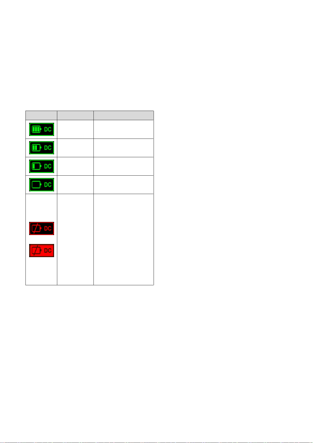
3.2 Battery Status Display Screen
When the ventilator is operated using battery,
remaining operation time of the battery is
displayed on the bottom right corner of the
screen.
MV2000[SU:M] Ventilator MEKICS Co., Ltd
16
Page 26
3. Power Supply
Display
Status
Description
Full
Charging
100% charged
80%
Charging
80% charged
50%
Charging
50% charged
20%
Charging
20% charged
Low
Charging
If remaining battery is
low, the icon is
displayed on the
screen. In order to
protect the battery,
beep sound is created
and power is
automatically turned
off after about 5
minutes.
When battery state is low, battery icon on the
bottom right is displayed in red color. Here,
battery should be replaced or, if possible, connect
the ventilator to main power source.
Information on battery module inserted in the
ventilator is displayed as follows.
- Long-term storage may cause reduction in
battery capacity. Do not leave battery module
unattached or stored for long time. If it is
necessary to store a battery for short time,
fully charge the battery and store at low
temperature (15-20℃ or 59-68℉) under dry
environment.
- Stored or unused battery must be charged
before using.
- Disposed batteries must be handled in
accordance to local regulations. Do not
discard them with ordinary wastes.
- After replacing with new battery, check the
status of new battery for safe operation.
- Battery may not be fully charged upon initial
supply of the product. Use user interface to
check charging status. If necessary, connect
3.3 Alarm and Safety Devices
Battery status is always monitored by the
ventilator. Check the following precautions.
3.3.1 Warnings
- Check the battery prior to use for safe battery
backup operation.
- If low battery is displayed, battery must be
quickly replaced.
MV2000[SU:M] Ventilator MEKICS Co., Ltd
the ventilator to main power source to charge
the battery prior to use.
- Discharged battery must always be charged
for use.
- When the ventilator is not in use, it must
always be connected to main power source to
charge the battery.
3.3.2 AC Power Supply Failure
If there is no AC power supply or power outlet is
disconnected, the ventilator automatically operates
using battery.
17
Page 27
4. Operation Method
WARNING
- Always perform pre-use check prior to
connecting the ventilator to the patient.
- Do not connect the ventilator to the
patient in case of functional errors.
- When ventilator is in operation, do not
raise or separate expiratory cassette. If
necessary, take these actions in standby
mode or with the ventilator turned off.
4.1 Operation Sequence Summary
The following is summarized operation sequence
of MV2000[SU:M] ventilator.
1) Check of pre-use
2) Select the patient type.
4. Operation Method
3) Input patient information in the system menu.
4) Select ventilation mode.
5) Configure parameters for the selected
ventilation mode.
6) If necessary, check and adjust alarm range in
the alarm menu.
7) Connect the ventilator to the patient and push
Accept button in ventilation mode to start
ventilation.
8) During ventilation, user can make or change
the settings as below.
9) Parameter setting can be seen or changed
using direct access button.
Refer to the following section for detailed
description on individual sequence of ventilator
operation.
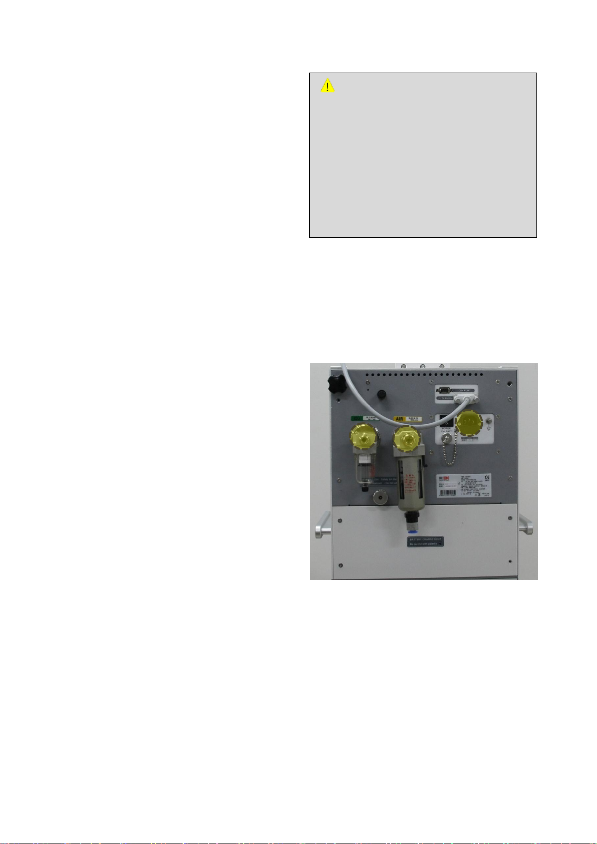
4.2.1 Start Up
1. Connect power and gas supply line.
- AC power
- Air, O
gas
2
4.2 Pre-Use Check
Test and measurement items during pre-use check
process are as follows.
- Gas supply status
- System function inspection
- Internal block leakage
- Pressure sensor
- Flow sensor
- O2 cell
- Battery status
- Leakage and compliance of patient tube
MV2000[SU:M] Ventilator MEKICS Co., Ltd
2. Turn on the ventilator.
18
Page 28
CAUTION
If the product is turned off during transition
to battery mode, re-inspect after charging or
replace the battery.
② ③ ④ ⑤ ⑥ ⑦ ①
3. The ventilator will inspect system function status,
pressure sensor, flow sensor, and gas supply
4. Operation Method
4.2.3 Tube Inspection for Patients
1) Connect patient tubes including humidifier
and nebulizer. If humidifier is used, water tank
in the humidifier must be filled with distilled
water.
2) Block Y piece and operate the product. Check
for tube leakage.
3) Operate the product after connecting test
lung to Y piece. Check the status of patient
tubes and ordinary operation.
4.3 Patient Information Input
status.
4. Once inspection is completed, the stand-by
screen will appear.
4.2.2 Auto transition Between AC Power
and Battery Power
During pre-use check, auto transition between AC
power and battery power from suspension or
reconnection of AC power supply must be tested.
- Check icon on the screen to see whether the
ventilator is in AC mode.
- Unplug the AC plug to block power source.
- Check whether icon is changed to battery
mode. If there is no problem in icon change,
reconnect the AC plug.
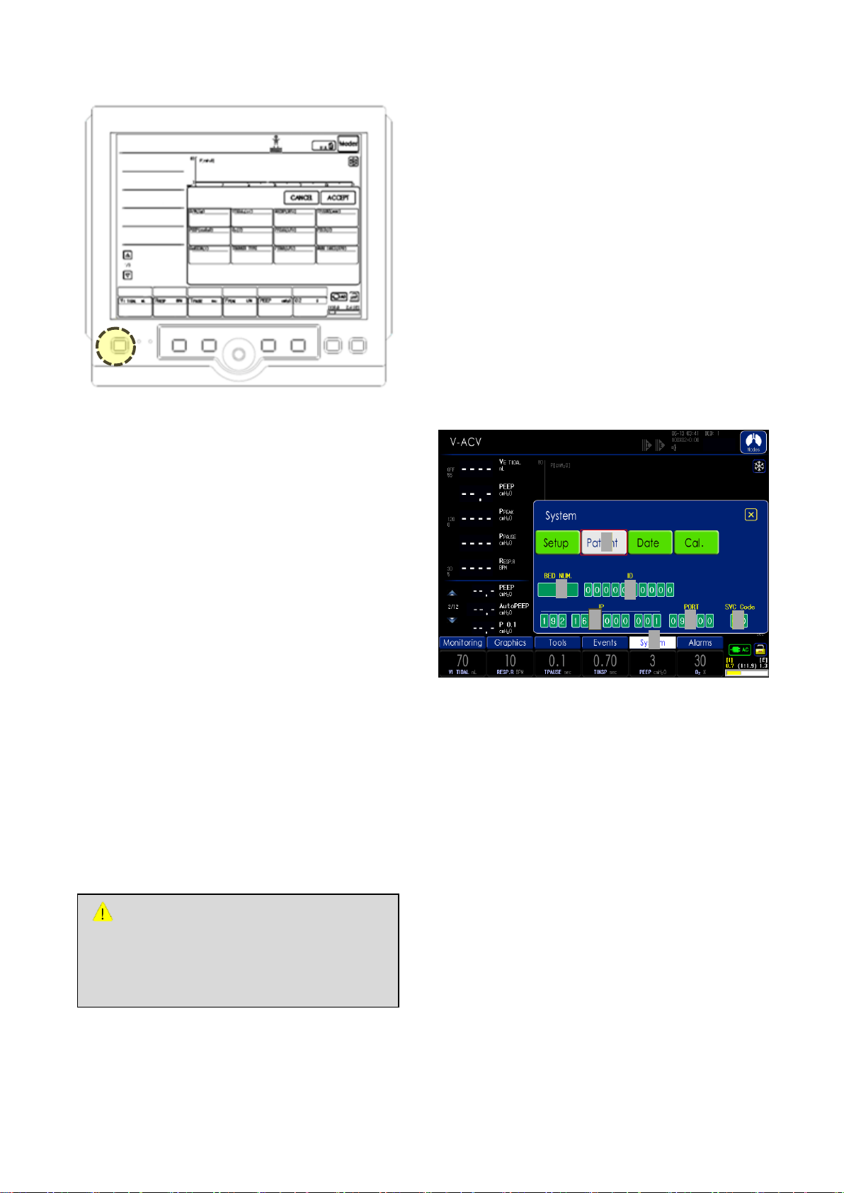
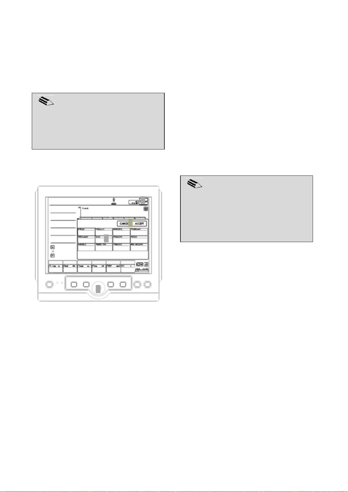
1) Select system menu on the bottom of user
interface.
2) Enter patient menu.
In input window of the patient information,
the following information can be entered or
modified.
3) Bed number
4) Patient ID number
MV2000[SU:M] Ventilator MEKICS Co., Ltd
5) IP address for communication (external
connection using LAN)
6) Port number for communication (external
connection using LAN)
7) Password (password (77) for IP and port input)
19
Page 29
4. Operation Method
NOTE
Consider alarm auto function prior to
application in a patient. If auto function is
inappropriate, configure alarms directly.
Alarm auto function is configured based on
the patient’s body weight.
NOTE
Input and modification can be done using
the same method as setting configuration
using touch screen. Encoder can also be
used.
① ② ③
④
After completion of input and modification, return
to stand-by screen and enter the patient’s height.
Body weight and setting values for each mode are
defined based on internal calculations.
4.4 Ventilation Mode and Parameter
Setting
4.5 Alarm Setting
Alarm Setting
1. Touch the alarms button on the bottom of
user interface.
2. Select alarm value to adjust.
3. Rotate the encoder to change and modify
the value.
4. Touch the value again or push the
encoder to save changes.
5. Alarm values can be automatically
configured using alarm auto button.
Ventilation Mode and Parameter Setting
1) Push Mode.
2) Select the mode to use in the activated
ventilation mode window. Once a ventilation
mode is selected, parameters required for the
selected mode are displayed.
3) Select parameters for which values must be
changed, and use the encoder to adjust their
values. After adjusting the parameter, re-select
the parameter for deactivation or push the
encoder to save the adjusted value.
4) Once setting value is saved, push Accept
button to operate with saved value or push
Cancel to cancel.
MV2000[SU:M] Ventilator MEKICS Co., Ltd
4.6 Starting Ventilation
As in 4.4, select ventilation mode, configure
parameters, and touch Accept button to operate
the ventilator.
If standby key is pushed during operation of the
ventilator, window pops up to ask whether to
move to standby mode. The ventilator converts to
standby mode once Standby button is pushed.
Push X on the top right corner to cancel.
4.7 Change in Patient Type
MV2000[SU:M] ventilator can select among four
patient type in standby mode.
- Male (Adult)
- Female (Adult)
- Pediatric
- Neonate (Infant)
20
Page 30
4. Operation Method
NOTE
New setting values are applied after
deactivation of corresponding parameter
button.
NOTE
Always check alarm setting after changing
the range of patient.
NOTE
Default values of the ventilator system on
adults and infants can arbitrarily be changed
by user.
NOTE
When patient type is changed, the following
default values or setting values are changed.
- Default alarm values
- Alarm setting range
- Default parameter values
- Parameter range
4.9 Measurement Sensor Calibration
If the ventilator is continuously used for long time,
measurement values may slightly differ.
Measurement sensors must be calibrated.
Calibration of measurement sensor:
1. Select system in the menu on the bottom of
user interface. Select Cal. among sub menu.
2. The following sensors must be calibrated.
- Flow Zeroing
(Flow Sensor Offset)
4.8 Change in Setting Parameter
In order to change setting parameters during
ventilation, push the speed button.
To adjust parameters of ventilation mode,
1) Activate the parameter by touching the
wanted speed button.
2) Configure wanted value using encoder.
3) Touch again to deactivate.
- Exp. Flow Gain
(Expiratory Flow Sensor Balance)
- Adult Prox. Flow Gain
(Adult Proximal Flow Sensor Balance)
- Neo. Prox. Flow Gain
(Neonate Proximal Flow Sensor Balance)
- O2 Cell Cal.(O2 Sensor)
- Leak Test
- EtCO2 Zeroing(EtCO2 Module)
4.9.1 Flow Zeroing
Flow zeroing is an automatic offset adjustment
MV2000[SU:M] Ventilator MEKICS Co., Ltd
function on inspiratory and expiratory flow sensor.
Calibration starts by pushing Start button after
rotating the encoder. Calibration is completed
after a moment.
4.9.2 Expiratory Flow Gain
Adjust the balance of inspiration flow and
expiration flow. Ratio of inspiration volume to
expiration volume can be adjusted. If you
21
Page 31
4. Operation Method
NOTE
If O2 cell has been exp ired, replace the cell
before performing calibration.
expiratory flow gain’ value increase, expiratory
measured value is increased.
4.9.3 Adult/Neonatal Proximal Flow
Gain
Adjust the balance of inspiration and proximal
flow. Connect proximal sensor to inspiratory outlet
port and select menu will start the calibration.
Calibration is completed after a moment.
4.9.4 O2 Cell Calibration
O2 cell may show incorrect O2 concentration due
to natural consumption of O2 cell with longer use.
Therefore, O2 concentration can be fixed through
calibration. With air supply connected, rotate the
encoder and select 21% menu to start with 21%
O2 calibration. Calibration is completed after a
moment.
4.10 Separation of Ventilator from
Patient
In order to separate the ventilator and stop
ventilation,
1) Separate the ventilator from the patient.
2) Push standby key to convert to standby mode.
3) Once ventilation stops, push Power button to
turn off the ventilator.
4) When power is turned off, turn off the main
power switch on the back of the main body.
While 100% O2 is being supplied, 100% O2
calibration can be started by rotating the encoder
and selecting 100% menu. Calibration is
completed after a moment.
4.9.5 Leakage Test
Analysis of leakage and compliance is conducted.
First, directly connect the breathing circuit to
inspiratory port and expiratory port. Rotate the
encoder and push Start menu to start calibration.
Analysis ends after a moment.
4.9.6 EtCO2 Zeroing
If the ventilator has EtCO2 module, calibration is
performed. Rotate the encoder and push Start to
start with EtCO2 calibration. EtCO2 calibration is
completed after a moment.
MV2000[SU:M] Ventilator MEKICS Co., Ltd
22
Page 32
5. Monitor and Information Saving
5. Monitor and Information
Saving
5.1 Measurement Value Display
Measurement and calculation values during
ventilation are displayed.
This Section includes descriptions on screen
display, additional display window on
measurement and calculation values, and list of all
values displayed.
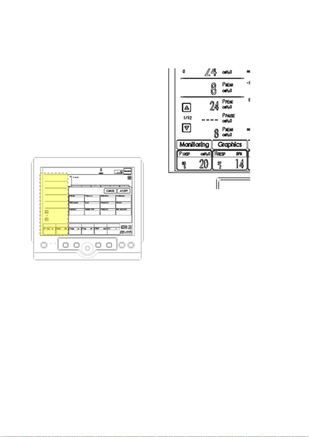
5.1.1 Measurement Value Screen
5.1.2 Additional Measurement Display
Screen
To see more measurement values,
Measured parameters and the following details are
displayed on left side of the screen.
1) Alarm Limit
2) If value lies outside upper and lower limits of
Alarm Limit, the value is displayed in red.
3) If value cannot be measured, it is displayed as
‘----‘.
4) Parameters displayed on measurement value
screen can be changed in connection with
1) Touch the arrows pointing up and down on
the bottom left corner of the screen.
2) Measurement values can be seen up to a
maximum of 12 pages.
3) Check monitoring menu to see measurement
values at once.
monitoring menu.
MV2000[SU:M] Ventilator MEKICS Co., Ltd
23
Page 33

5.1.3 List of Measurement and Calculation Values
P PEAK
cmH2O
Maximum inspiratory pressure
P PAUSE
cmH2O
Pressure during end-inspiratory pause
P MEAN
cmH2O
Mean airway pressure
PEEP
cmH2O
Positive end expiratory pressure
Auto PEEP
cmH2O
Difference between measured PEEP and configured PEEP
P 0.1
cmH2O
Indicator for respiratory drive
VI TIDAL
mL
Inspiratory tidal volume (per breath)
VE TIDAL
mL
Expiratory tidal volume (per breath)
VE MIN
LPM
Expiratory minute volume (per minute)
PEEP H
cmH2O
High PEEP
PEEP L
cmH2O
Low PEEP
F PEAK
LPM
Maximum inspiratory flow
RESP.R
BPM
Respiration
RR SPONT
BPM
Respiration rate in spontaneous breath
VEMIN
SPONT
LPM
Expiratory volume per min in spontaneous breath
TI
sec
Inspiration time
TE
sec
Expiration time
I : E
Inspiration to expiration ratio
Exp.Flow
LPM
Expiration flow
RSBi
b/min/mL
Rapid shallow breathing index
O2 % Oxygen concentration in volume %
CL
mL/ cmH2O
Compliance
RA
cmH2O /s
Resistance
WOBv
J/L
Work of Breathing Ventilator
PR
BPM
Pulse Rate
SpO2
%
Oxygen saturation in blood
EtCO2
mmHg
End tidal carbon dioxide
Ins
mmHg
Inspiratory carbon dioxide
RESP
RPM
Respiration through EtCO2
VI CO2
ml
Inspiratory CO2 Tidal Volume
VE CO2
ml
Expiratory CO2 Tidal Volume
VE MIN CO2
ml
Expiratory Minute CO2 Volume
VE STROKE
ml
Expiratory CO2 Tidal Volume
H.Freq
Hz
Frequency
5. Monitor and Information Saving
MV2000[SU:M] Ventilator MEKICS Co., Ltd
24
Page 34
5. Monitor and Information Saving
5.2 Waveform Display
When SpO2 and EtCO2 options are connected,
color-wise waveforms are displayed on the screen
as follows. Up to four waveforms can be displayed
on the screen.
- Pressure vs. time
- Flow vs. Time
- Volume vs. Time
- SpO
- EtCO
vs. Time
2
vs. Time
2
5.2.1 Characteristics
Waveforms are displayed on the screen as follows.
Measured parameter values are displayed
according to time axis.
- Parameter and scale are displayed on Y axis.
- Pressure vs. time graph is displayed in dark
5.2.2 Waveform Setting and Change
Layout and trend timing of waveform can be
configured and changed through [Graphics] menu
on the bottom of user interface.
To change displayed graphs, touch waveform. The
following window appears for each graph,
allowing user to select wanted graphs.
pink.
- Flow vs. time graph is displayed in dark sky-
blue.
- Volume vs. time graph is displayed in white.
- SpO
- EtCO
vs. time graph is displayed in yellow.
2
vs. time graph is displayed in white.
2
- Waveform : Pressure, Flow, Volume
If SpO2 and EtCO2 modules are connected
through option, two additional graphs can be
viewed.
- Loop : P-V, V-F, P-F
- Trend : VE min, Pmean, Ppeak, VTe, CL, RA
There are five screen layouts available as follows.
MV2000[SU:M] Ventilator MEKICS Co., Ltd
25
Page 35
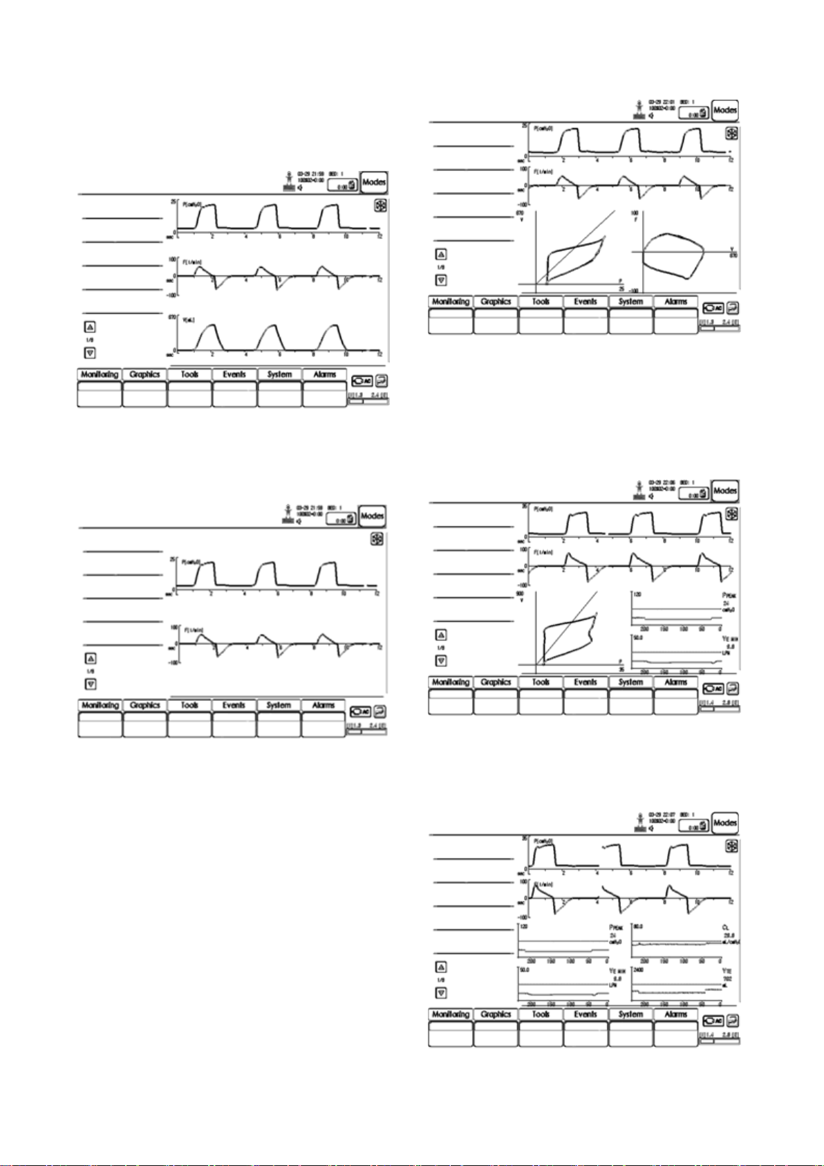
- Layout 1: Three waveform graphs are
displayed among pressure, flow, volume, SpO2
and EtCO2.
5. Monitor and Information Saving
- Layout 4: Two waveform graphs are displayed
- Layout 2: Two waveform graphs are displayed
among pressure, flow, volume, SpO2 and
EtCO2.
- Layout 3: Two waveform graphs are displayed
among pressure, flow, volume, SpO2 and
EtCO2. One Loop graph is displayed among PV, V-F and P-F. Two trend graphs are
displayed.
- Layout 5: Two waveform graphs are displayed
among pressure, flow, volume, SpO2 and
among pressure, flow, volume, SpO2 and
EtCO2. Two loops are displayed among P-V,
V-F and P-F.
EtCO2. Four trend graphs are displayed.
MV2000[SU:M] Ventilator MEKICS Co., Ltd
26
Page 36
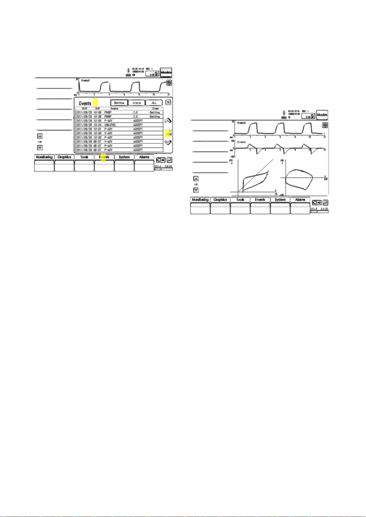
5. Monitor and Information Saving
② ③ ①
5.3 Event Log
To check the event log:
1) Select events menu on the bottom of user
interface.
2) All recorded events can be seen in events
5.4 Loop
Loops function displays the relationship among
Pressure-Flow, Flow-Volume, and Pressure-Volume
as graphs.
menu.
A. Setting: History of changes in setting is
recorded.
B. Alarm: History of alarms is recorded.
C. ALL: History of setting changes and
alarms are recorded. All events can be
seen.
3) Use arrows on the right side to search
through the list of events.
Refer to Section 5.2.2 for loops graph setting.
5.5 Trend
Trend value is saved every time the patient
respires. Trend timing configured in graphics menu
refers to the step in which trend data can be
searched.
Trend timing in graphics menu can be configured
as follows.
- 1RESP
- 10RESP
- 30RESP
- 60RESP
If 1 RESP is designated, Trend data can be
searched at every respiration.
Refer to Section 5.2.2 for trend graph. Trend
graphs can be seen using Layout 4 and Layout 5.
27
MV2000[SU:M] Ventilator MEKICS Co., Ltd
Page 37
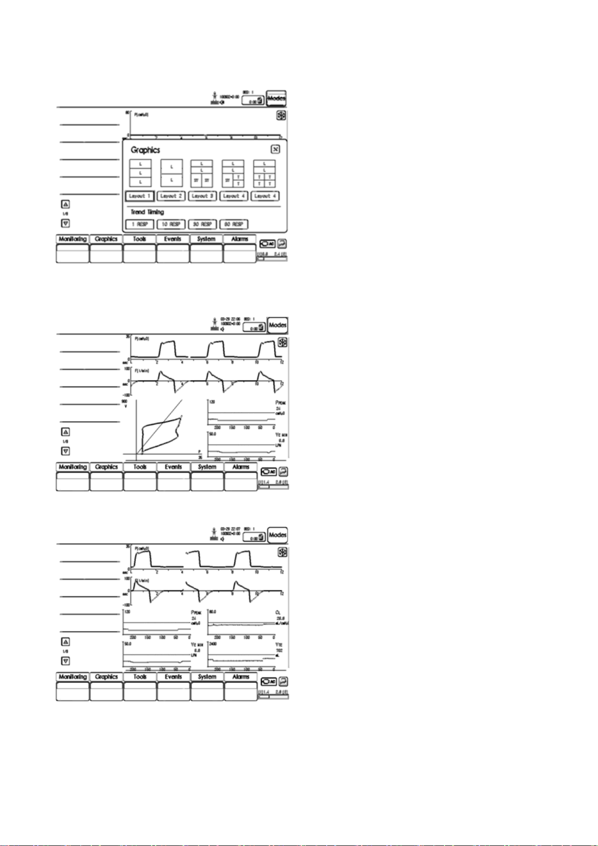
5. Monitor and Information Saving
Trend Setting and Graph Sequence Diagram
- Graphics menu
- Layout 4
- Layout 5
MV2000[SU:M] Ventilator MEKICS Co., Ltd
28
Page 38

6. Ventilation Mode and Function
WARNING
- Alarm setting for each ventilation mode
must be configured appropriately. In
particular, be careful for the following
alarms.
Minute volume or tidal volume
Apnea alarm
- In order to prevent risk of self-
triggering, do not configure trigger
sensitivity as too high (sensitive).
- Be careful about upper pressure alarm
setting to protect the patient’s lungs
from excessive pressure.
- Excessive inspiratory pressure can
cause swelling of abdomen or
aspiration. It may also be a cause of
excessive leakage (only applied in Mask
Mode).
NOTE
Not all warnings below are applied to all
ventilation modes.
NOTE
MV2000[SU:M] Ventilator System is delivered
according to the following setting method.
- Setting of parameters are based on
minute volume or Tidal Volume
- Setting of parameters are based on I:E
ratio or inspiration time
6. Ventilation Mode and Function
6.1 Introduction
Diverse ventilation modes can be used in
MV2000[SU:M] Ventilator System. This Chapter
describes the ventilation modes, their settings, and
associated safety information.
Refer to technical specifications for description on
default settings and range of each parameter for
the system.
6.1.1 Warnings
MV2000[SU:M] Ventilator MEKICS Co., Ltd
6.1.2 Types of Ventilation
The ventilator provides the following ventilations.
1. Controlled Ventilation
2. Supported Ventilation
3. Spontaneous Breathing/CPAP
It also allows for combined ventilator control or
support. Spontaneous breathing efforts are sensed
during controlled ventilation (ex: SIMV
functionality).
The AutoVent functionality continuously adapts to
the patient’s breathing capability.
When required, all ventilation is provided for
mandatorily. When the patient is able to initiate a
breath, the ventilator supports and monitors the
patient’s breathing capability and controls
ventilation only if required.
29
Page 39
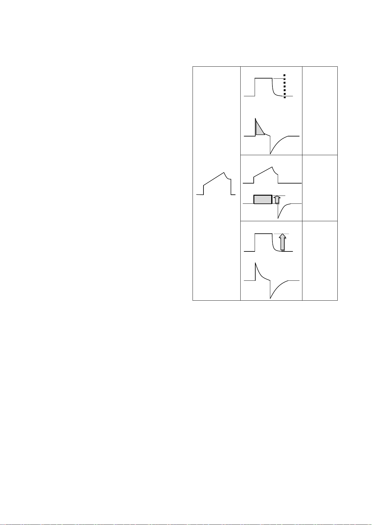
6. Ventilation Mode and Function
Pressure
Time
Flow
Pressure
and
Volume
Pressure
Flow
Flow
/Volume
Pressure
Flow
Pressure
① ② ③
Time
Time
Time
Time
Time
6.1.3 Ventilation Control Method
Ventilation is controlled by the following elements.
A. Pressure and Volume
B. Pressure
C. Flow/Volume
Pressure and Volume
This method guarantees constant inspiratory tidal
volume per respiration by controlling pressure and
flow. Inspiratory pressure level is maintained
constant during each breath. (PRVC, Volume
Support).
Pressure
Pressure level configured during inspiration time is
6.1.4 Summary of Ventilation Modes
maintained constant.(Pressure control, Pressure
Support)
Flow/Volume
Tidal volume per respiration is maintained
constant during inspiration time by flow / volume
control. Inspiratory flow is maintained constant
during breath(Volume Control)
Extra Flow and Extra breaths
If demanded flow by the patient can be triggered
during inspiration time, additional flow is delivered.
Also, if the patient’s effort for ventilation coincides
with conditions of trigger sensitivity, tidal volume
is delivered from the ventilator.
Timing
Timing in controlled ventilation mode is
determined by configured time. Timing in
supported ventilation is decided by the patient’s
effort for ventilation and configured inspiratory
cycle off.
MV2000[SU:M] Ventilator MEKICS Co., Ltd
1. Pressure Regulated Volume Control (PRVC)
(Volume control ventilation by auto pressure
control)
While maintaining configured tidal volume,
controlled ventilation is delivered at constant
inspiratory pressure for each breath depending on
the lung status of the patient. Flow is delivered
using decelerating method.
2. Volume Control (VC)
(Controlled ventilation by volume method)
While maintaining configured tidal volume,
mechanical ventilation is delivered using constant
flow pattern method.
3. Pressure Control (PC)
30
Page 40
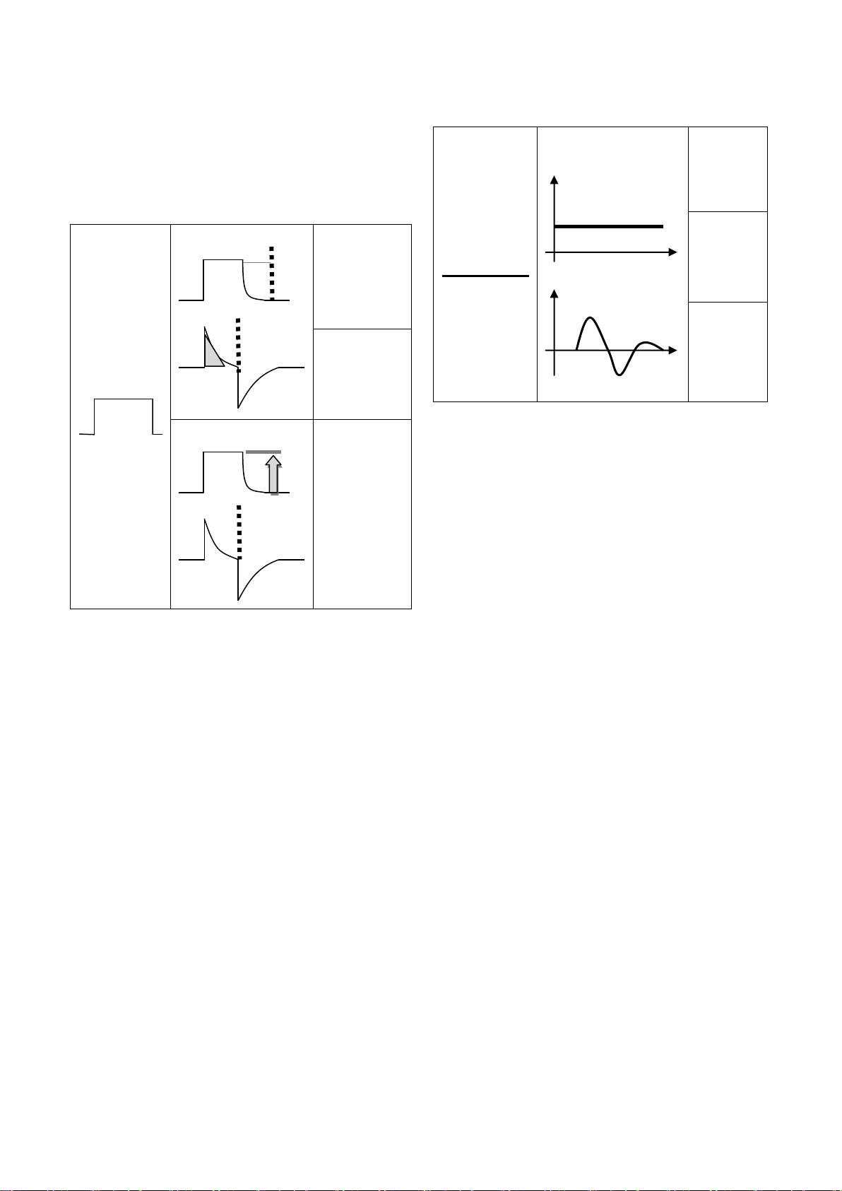
6. Ventilation Mode and Function
Pressure
Flow
Pressure and
Volume
Flow
/Volume
Pressure
Flow
Pressure
Pressure
Flow
Pressure
and
Volume
Flow
/Volume
Pressure
⑤
④ ⑥ ⑦
Time
Time
Time
Time
Time
Time
(Controlled ventilation by pressure method)
Mechanical ventilation is delivered using
decelerating flow pattern method according to
configured pressure level.
6. Spontaneous Breathing
If the patient obtains sufficient volume in volume
support, spontaneous breathing can be permitted
without support by the ventilator.
4. Volume Support (VS)
(Volume support ventilation method by auto
pressure control)
Supported ventilation is delivered by constant
inspiratory pressure according to the patient’s
effort for respiration. Delivered volume is
monitored, and inspiratory pressure is
automatically adjusted as necessary. Patient
decides the number of respirations and inspiratory
time. Flow is delivered using decelerating method.
5. Pressure Support (PS)
(Supported ventilation by pressure method)
Supported ventilation is delivered based on
configured pressure level according to the
patient’s effort for respiration. Patient decides the
number of respirations and respiration time. Flow
pattern is delivered using decelerating method.
7. Spontaneous breathing / CPAP
(Spontaneous breathing through maintenance of
positive airway pressure)
Spontaneous breathing of the patient occurs when
inspiratory pressure level is configured as zero in
pressure support.
O2 Stream
Spontaneous breathing on a set flow level(High
flow). The flows that exceed patient demands at
various minute volumes. O2 Stream affects CO2
ventiatlion, efficient oxygenation, work of
breathing and energy cost of gas conditioning.
AutoVent
The ventilator continuously adapts to the patient’s
breathing capability and allows the patient to
better interact with the ventilator. The ventilator
automatically shifts between controlled ventilation,
supported ventilation and spontaneous ventilation.
31
MV2000[SU:M] Ventilator MEKICS Co., Ltd
Page 41

Each controlled ventilation mode has a
corresponding support mode.
Volume Control --- Volume Support
PRVC --- Volume Support
Pressure Control --- Pressure Support
When the patient is making a breathing effort, the
ventilator immediately switches to a support mode
of ventilation. If the patient is not making any
breathing effort, the ventilator will return to the
controlled mode and deliver controlled breaths.
Synchronized Intermittent Mandatory
Ventilation (SIMV)
6. Ventilation Mode and Function
The ventilator provides mandatory breaths which
are synchronized with the patient’s spontaneous
efforts at a preset rate. The mandatory breaths
can be Volume Control, Pressure Control or PRVC
breaths.
tBiLevel
tBiLevel is pressure controlled breathing, giving
the patient the opportunity of unrestricted
spontaneous breathing. Two pressure levels are set
together with the individually set duration of each
level. Spontaneous efforts can be assisted by
pressure support.
TCPL
A peak inspiratory pressure is set by the operator,
and during inspiration gas flow is delivered to
achieve that set pressure.
The volume of gas delivered to the patient in this
TCPL varies depending on pulmonary mechanics
such as compliance of stiffness of the lungs.
MV2000[SU:M] Ventilator MEKICS Co., Ltd
32
Page 42
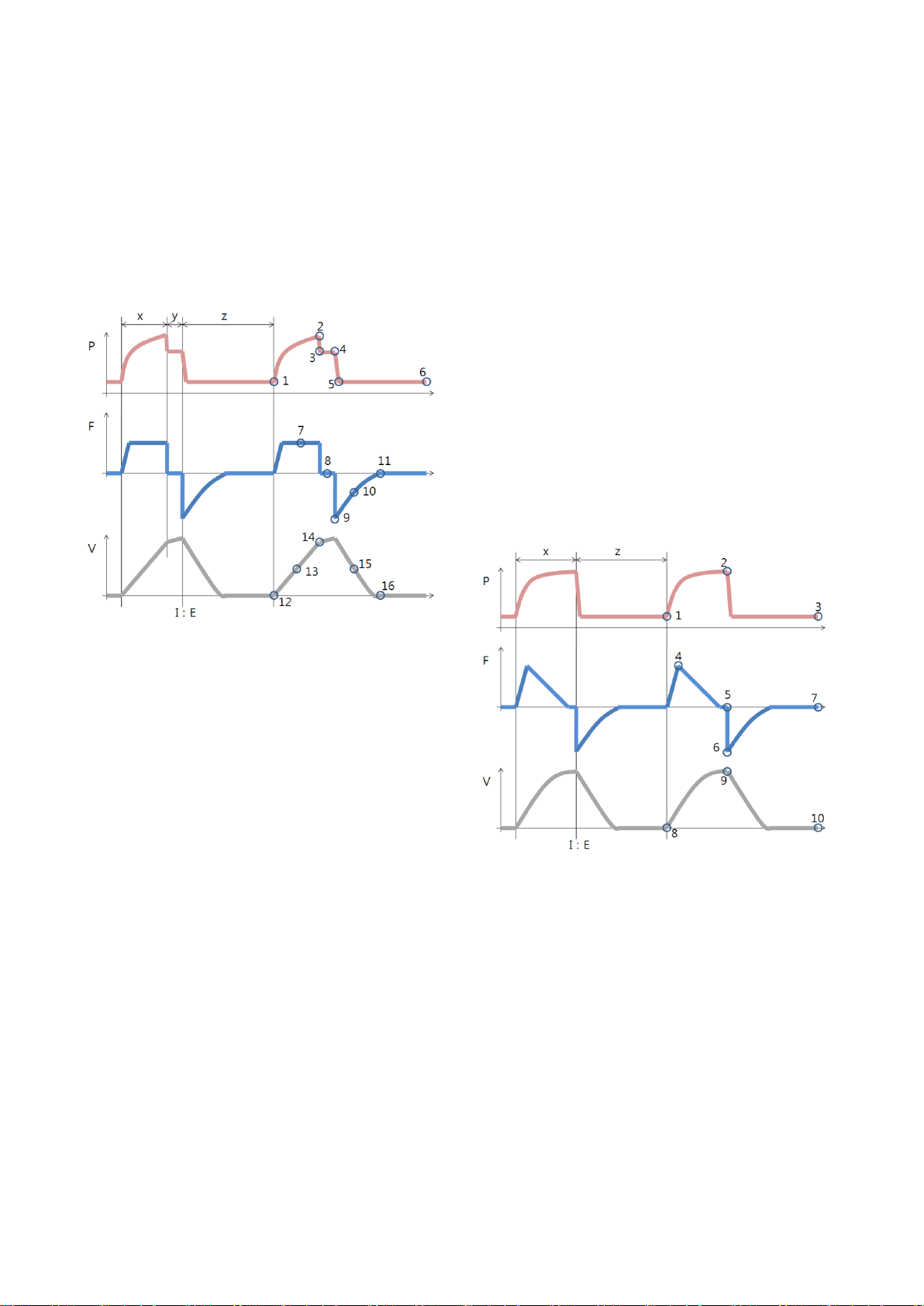
6. Ventilation Mode and Function
6.2 Waveform Description
The graphic display for flow, pressure and volume
is displayed in waveforms. Patterns for flow,
pressure and volume differ directly according to
each ventilation mode.
6.2.1 Volume Control
11. End expiratory flow
Volume-Time Waveform
X. Inspiration time
Y. Pause time
Z. Expiration time
12. Start of Inspiration
13. The Slope displays inspiratory tidal volume per
respiration
14. End Inspiration
15. The Slope displays expiratory tidal volume per
respiration
16. End expiration
6.2.2 Pressure Control
Pressure-Time Waveform
X. Inspiration time
Y. Pause time
Z. Expiration time
1. Start of Inspiration
2. Peak inspiratory pressure
3. Early inspiratory pause pressure
4. End inspiratory pause pressure
5. Early Expiratory pressure
6. End Expiratory pressure
Flow-Time Waveform
X. Inspiration time
Y. Pause time
Z. Expiration time
7. Peak inspiratory flow
8. Zero flow phase
9. Peak expiratory flow
10. Slope decelerating expiratory limb
Pressure-Time Waveform
X. Inspiration time
Z. Expiration time
1. Start of Inspiration
2. Peak inspiratory pressure
3. End Expiratory pressure
Flow-Time Waveform
X. Inspiration time
Z. Expiration time
MV2000[SU:M] Ventilator MEKICS Co., Ltd
33
Page 43
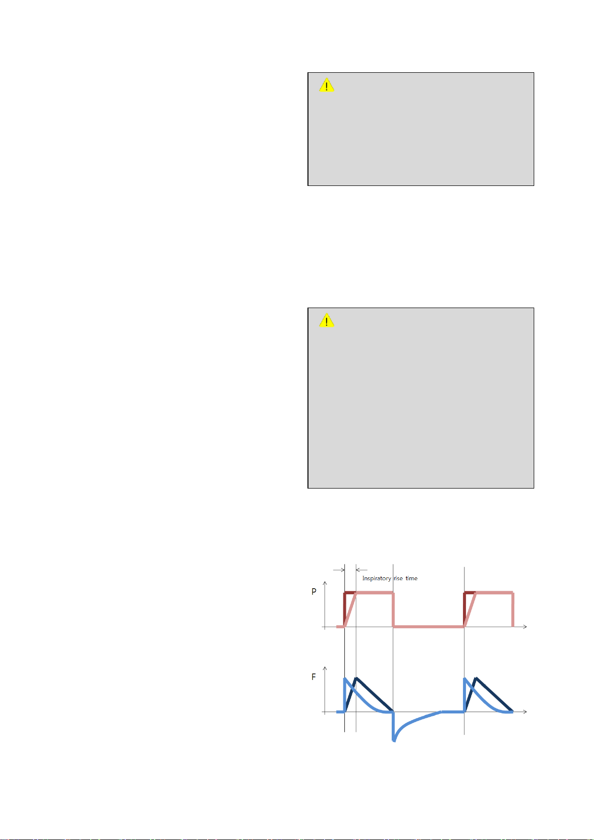
4. Peak inspiratory flow
WARNING
- If the trigger sensitivity is set too high, a
self triggering (auto-triggering)
condition may be reached. This
condition can also be reached if there is
leakage in the breathing system.
- Triggering will then be initiated by the
system and not by the patient. This
should always be avoided by decreasing
the trigger sensitivity.
WARNING
- The trigger sensitivity bar has different
colors based on the setting. A light blue
bar indicates a normal setting for flow.
A red bar indicates that triggering is
required for flow.
5. End inspiratory flow
6. Peak expiratory flow
7. End expiratory flow
Volume-Time Waveform
X. Inspiration time
Z. Expiration time
8. Start of Inspiration
9. End Inspiration
10. End expiration
6.3 Setting Parameter Description
6.3.1 Trigger Function
6. Ventilation Mode and Function
The ventilator continuously delivers a gas flow
during expiration, which is measured in the
expiratory channel.
1. Inspiration
Bias flow during expiration is 8 l/min.
Trigger sensitivity determines the patient’s effort
during breath to induce ventilation from ventilator.
Trigger sensitivity can be configured using flow
trigger(FTRIG) or pressure trigger(PTRIG) method.
In general, flow trigger method can reduce the
patient’s effort for breath.
Trigger sensitivity should be configured as high as
possible without resulting in self(auto)-triggering.
Such setting increases patient-triggered ventilation
and reduces auto-cycling by the ventilator.
Pressure trigger can be configured within the
range of 0.5 ~ 20 cmH2O (pressure trigger setting
is also related to PEEP setting).
6.3.2 Inspiratory Rise Time
(Time adjustment from starting point of inspiration
to time of peak flow or peak pressure)
Flow trigger refers to the amount of bias flow that
must be inhaled by the patient to induce new
breath.
MV2000[SU:M] Ventilator MEKICS Co., Ltd
34
Page 44

6. Ventilation Mode and Function
At the starting point of inspiration for each breath,
it can be adjusted the arrival time to peak flow or
peak pressure as second or percent of respiratory
cycle. If rise time is high, increased flow/pressure
and it is displayed through flow and pressure
waveforms
Inspiratory rise time is applicable in Pressure
Control, PRVC, SIMV-Pressure Control.
Configuration of inspiratory rise time is 0.1 ~
0.5sec.
In general, rise time must be configured higher
than default system value in order to deliver
comfortable ventilation to the patient in support
mode.
6.3.3 Respiration Rate
Respiration rate refers to the number of
respirations or breaths per minute. The respiratory
rate is also used for calculation of tidal volume if
the ventilator is configured for Minute volume
setting.
6.3.4 Apnea Time
Apnea time refers to set apnea time until
beginning of controlled ventilation in Spont mode.
Range of setting is 2 ~ 60sec.
6.3.5 PEEP
Setting range of Positive End Expiratory Pressure
(PEEP) is 0 ~ 45cmH2O. PEEP is maintained in the
alveoli and may prevent the collapse of the
airways.
6.3.6 I:E Ratio / Inspiratory Time
Inspiratory time setting in MV2000[SU:M]
ventilator can be done in the following two
methods.
- I:E ratio (regardless of change in respiration)
- Setting of inspiration time (regardless of
change in respiration)
Once inspiration time is configured in the
ventilator, pause time and inspiratory rise time are
automatically changed. Change in I:E ratio
according to inspiration time and pause time is
displayed in information window on the bottom
right corner of user interface.
6.3.7 Volume Level Setting
During initial setting for each mode of
MV2000[SU:M] ventilator, volume of air supplied
to the patient can be configured by adjusting
inspiratory tidal volume.
6.3.8 Controlled / Supported Pressure
Level
In controlled pressure mode, inspiratory pressure
(P. INSP) can be configured. Supplementary
pressure (P. SUPP) can be configured in supported
Pressure Support, SIMV modes and tBiLevel.
6.3.9 O2 Concentration
The setting range of O2 concentration is 21 ~
100%.
There is also an absolute minimum limit of alarm
is 18% O2 which is independent of operating
setting. If the value reaches below this point, O2
fail alarm will sound.
The screen only displays O2 concentration of 21%
or higher. The alarm is delayed 60 seconds after
changing the O2 concentration setting.
6.3.10 Proximal Sensor On/Off
This option must be used for low flow pressure /
flow supplemented patients who require precise
flow measurements and tube compensation such
MV2000[SU:M] Ventilator MEKICS Co., Ltd
35
Page 45
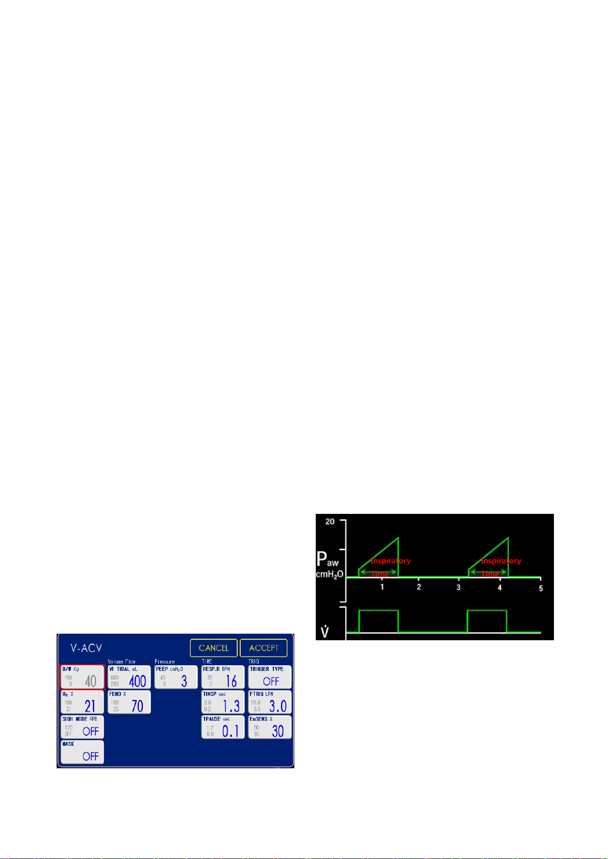
6. Ventilation Mode and Function
as premature and neonate patients.
It is safe to use this function in supported
ventilation below 200ml.
Appropriate sensor (for adults, for infants) must be
used depending on the patient.
6.3.11 Mask On/Off
This option can be turned On/Off in all modes
except for O2 stream and HFV.
Once turned On, leakage compensation ability is
increased.
6.3.12 Previous Mode
1. Time when previous mode was inactivated
2. Name of the previous mode
3. Press the pad Show previous mode to recall the
previous accepted ventilation mode.
4. Activate the previous used ventilation mode
settings by pressing the Accept pad.
6.4 V-ACV
(Volume Controlled Ventilation)
Volume control mode is based on mechanical
ventilation method and the ventilator delivers
The following parameters are configured in VACV
mode.
1. Tidal Volume(ml)
2. Respiratory Rate(b/min)
3. Pause Time(sec)
4. PEEP(cmH
5. Oxygen Concentration(%)
6. Inspiratory Time(sec)
7. End Flow(%)
8. Inspiratory Trigger Sensitivity(%)
9. Trigger Flow/Trigger Pressure
10. Trigger Setting(lpm/ cmH
11. Sigh Mode
12. Mask Mode(On/Off)
The airway pressure is dependent on the tidal
volume, inspiration time and the resistance and
compliance of the respiratory system. The set tidal
volume will always be delivered. An increase in the
resistance and decrease in compliance will lead to
an increased airway pressure. To protect the
patient’s lungs from excessive pressure, it is very
important to set the upper pressure limit to a
suitable value.
O)
2
O)
2
configured tidal volume to the patient.
VACV mode is a mode that controls mechanical
ventilation of the patient based on air volume. It
controls inspiratory and expiratory times by force.
It is possible for the patient to trigger extra
breaths if they can overcome the pre-set trigger
sensitivity. It is also possible for the patient, by
their own inspiratory efforts, to receive a higher
inspiratory flow and Tidal Volume during an
inspiration than pre-set.
MV2000[SU:M] Ventilator MEKICS Co., Ltd
36
Page 46
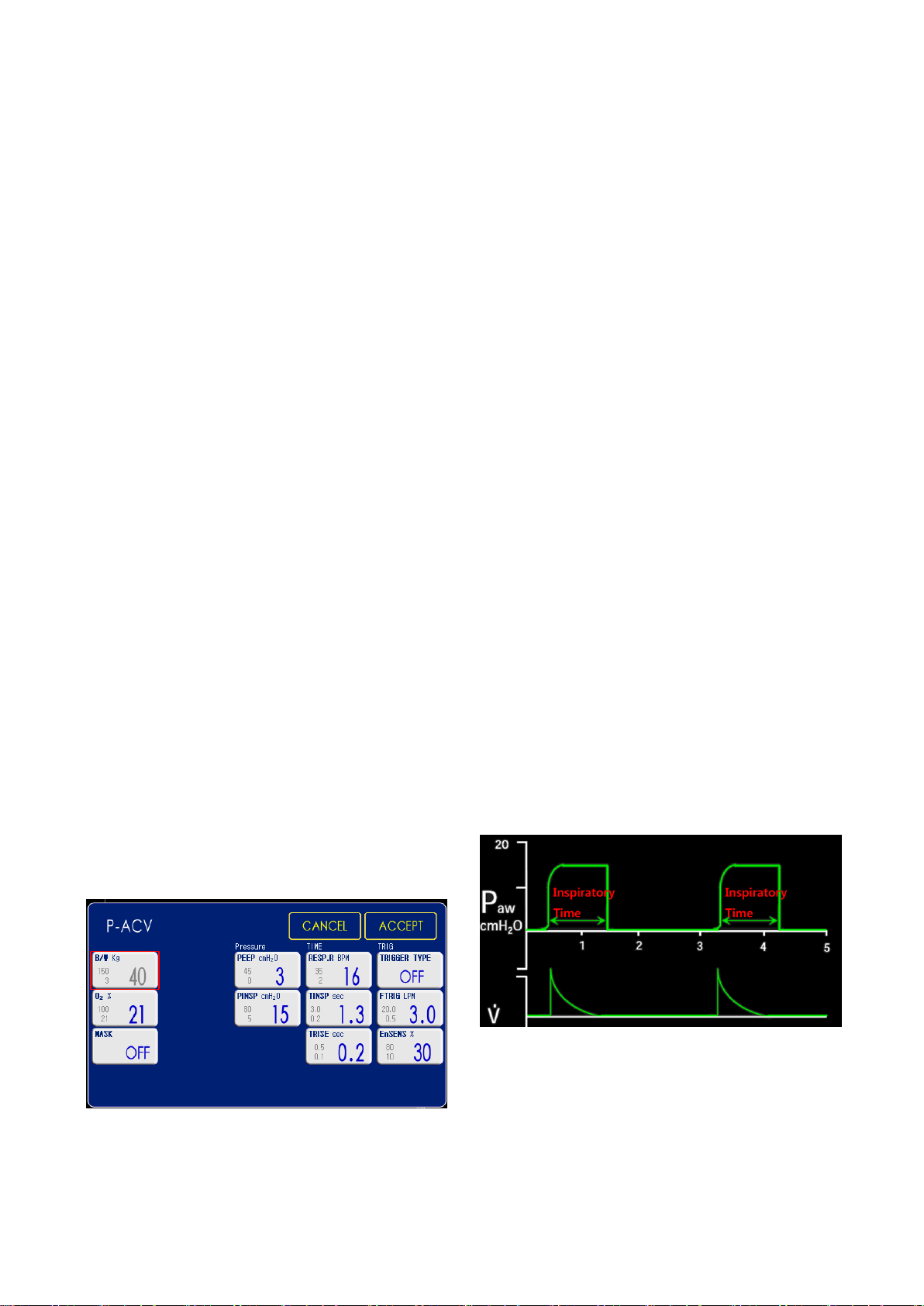
6. Ventilation Mode and Function
During volume control ventilation, peak flow is
determined after configuration of tidal volume
and inspiratory time. Also in addition to the above
two items, end flow and plateau are items that
influence peak flow.
Volume Control assures a preset tidal volume with
constant flow during a preset inspiratory time at a
preset frequency.
When the preset tidal volume is delivered and
after the preset pause time.
I:E ratio is determined by items that influence
inspiratory time and by respiratory rate.
1. Inspiration Pressure(cmH
2
O)
2. Inspiration Time(sec)
3. Respiratory Rate(b/min)
4. PEEP(cmH
O)
2
5. Oxygen Concentration(%)
6. Inspiration Rise Time(sec)
7. Inspiratory Trigger Sensitivity(%)
8. Trigger Flow/Trigger Pressure
9. Trigger Setting(lpm/ cmH
O)
2
10. Mask Mode(On/Off)
The delivered volume is dependent upon the
pressure above PEEP, lung compliance and
resistance in the patient tube system and airways.
This means that the Tidal Volume can vary.
As the delivered tidal volume can vary it is very
When changing setting values of I:E ratio or items
that influence inspiratory time, breath timing bar
is displayed to show changes in cycle time,
inspiratory time, expiratory time and I:E ratio.
6.5 P-ACV
(Pressure Controlled Ventilation)
Pressure control mode uses mechanical ventilation
method.
PACV is a mode that controls mechanical
ventilation of the patient based on pressure.
important to set alarm limits for Minute Volume to
adequate levels.
When pressure control ventilation is provided by
mandatory breath in assist / control mode,
inspiratory pressure is configured. Since pressure
is maintained constant during inspiration, flow
pattern is shown in the form of ramp. Plateau
function cannot be used.
Pressure Control assures that the preset
inspiratory pressure level is maintained constantly
The following parameters are configured in PACV
mode.
during the entire inspiration.
MV2000[SU:M] Ventilator MEKICS Co., Ltd
37
Page 47

The preset pressure level is controlled by the
ventilator. The resulting volume depends on the
set pressure level, inspiration time and the
patient’s lung mechanical properties during each
breath.
Since exhalation valve is active exhalation valve,
airway pressure control becomes more active and
precise. Accordingly, exhalation valve is used to
control increase in pressure caused by talking or
coughing of the patient during inspiration. It also
allows the patient to spontaneously breathe.
If the pressure increases to the set upper pressure
limit, the expiratory valve opens and the ventilator
6. Ventilation Mode and Function
switches to expiration.
MV2000[SU:M] Ventilator MEKICS Co., Ltd
38
Page 48

6. Ventilation Mode and Function
6.6 V-SIMV
(Volume based Synchronized
Intermittent Mandatory Ventilation)
V-SIMV is a mode that controls ventilation based
on volume according to spontaneous ventilation
of the patient. In other words, this mode
combined control and pressure support/
spontaneous function allows for preset mandatory
breaths synchronized with the patient’s breathing.
Spontaneous ventilation is done using configured
time period or mechanical ventilation is paralleled
based on air volume if there is no spontaneous
breathing.
The spontaneous/pressure supported breaths are
defined by the setting for Pressure Support.
11. Trigger Setting(lpm/ cmH
12. Pressure Support(cmH
13. Trise Pressure Support(cmH
2
O)
2
O)
2
O)
14. APNEA(sec)
15. Mask Mode(On/Off)
SIMV mode is a mode in which mandatory breath
and spontaneous breath are mixed.
SIMV mode guarantees one mandatory breath for
each SIMV cycle. Mandatory breath is either
Patient Initiated Mandatory (PIM or assisted
mandatory) breath or Ventilator Initiated
Mandatory (VIM or controlled mandatory) breath.
As in the following figure, each SIMV breath cycle
is divided into two parts. One is mandatory
interval (Tm) and another is spontaneous interval
(Ts). Once PIM breath is delivered, mandatory
The following parameters are configured in VSIMV
mode.
1. Tidal Volume(ml)
2. Respiratory Rate(b/min)
3. Pause Time(sec)
4. PEEP(cmH
2
O)
5. Oxygen Concentration(%)
6. Inspiratory Time(sec)
7. End Flow(%)
8. Inspiratory Trigger Sensitivity(%)
9. Expiratory Trigger Sensitivity(%)
10. Trigger Flow/ Trigger Pressure
interval ends and spontaneous interval (Ts) begins.
If PIM breath does not occur until the end of
mandatory interval, VIM breath is provided to the
patient as soon as mandatory interval ends and
spontaneous interval begins.
In SIMV mode, SIMV breath cycle is determined
by configured respiration. If respiratory rate is
configured as 12 times, SIMV breath cycle is 5
seconds. Mandatory interval is smaller value either
10 seconds or 0.6 x SIMV breath cycle. Mandatory
MV2000[SU:M] Ventilator MEKICS Co., Ltd
39
Page 49
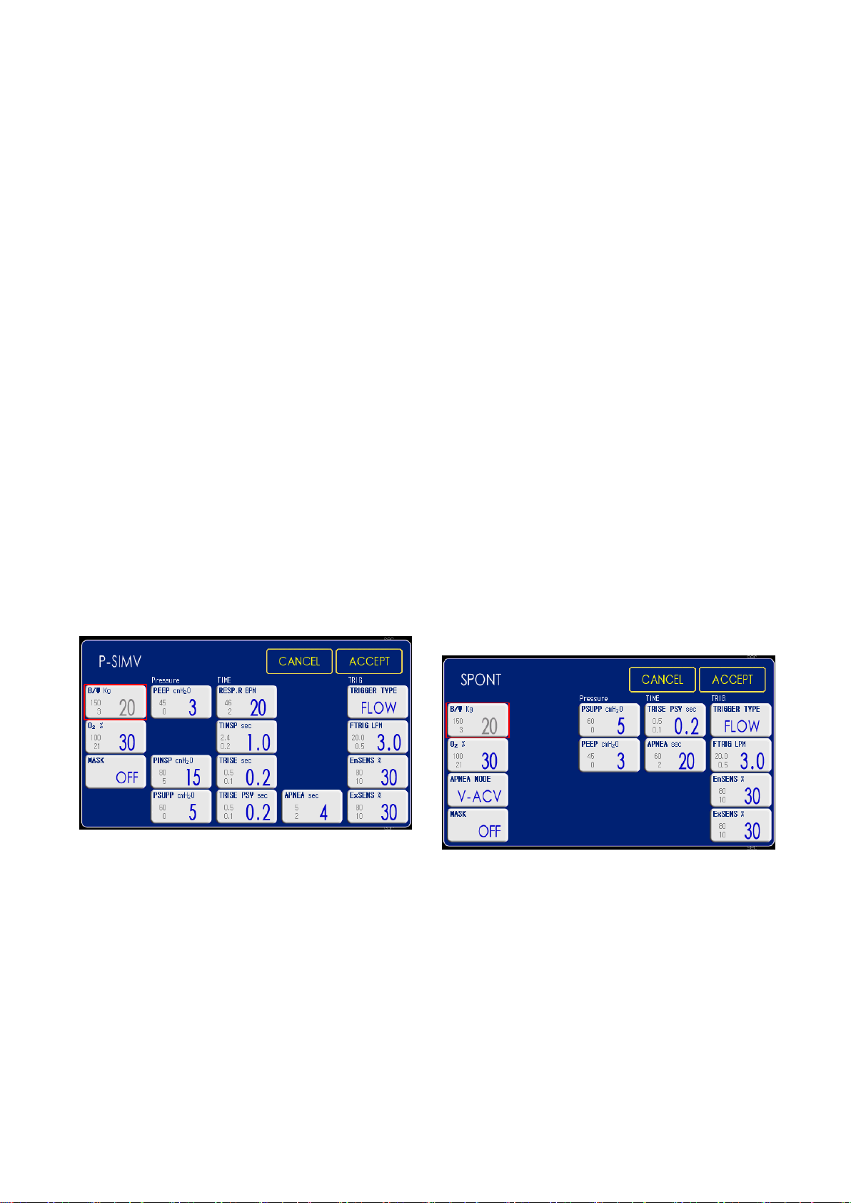
6. Ventilation Mode and Function
interval can be shortened depending on PIM
breath.
6.7 P-SIMV
(Pressure based Synchronized
Intermittent Mandatory Ventilation)
This mode controls ventilation based on pressure
according to spontaneous ventilation by the
patient. In other words, this mode combined
control and pressure support/spontaneous
function allows for preset mandatory breaths
synchronized with the patient’s breathing.
Mechanical ventilation is paralleled based on air
volume according to spontaneous ventilation or in
case there is no spontaneous ventilation using
configured time period.
The spontaneous/pressure supported breaths are
defined by the setting for Pressure Support.
7. Inspiratory Trigger Sensitivity(%)
8. Expiratory Trigger Sensitivity(%)
9. Trigger Flow/Trigger Pressure
10. Trigger Setting(lpm/ cmH
11. Trise Pressure Support(cmH
12. Pressure Support(cmH
2
O)
O)
2
2
O)
13. APNEA(sec)
14. Mask Mode(On/Off)
6.8 SPONT
(Spontaneous Ventilation)
This mode provides pressure support based on
spontaneous ventilation.
If there is no spontaneous ventilation for
configured time while operating in this mode,
mode is automatically converted to the mode (VACV or P-ACV) configured in Apnea Backup.
Mode returns to spontaneous ventilation once the
patient breathes three times spontaneously in 10
seconds.
The following parameters are configured in PSIMV mode.
1. Inspiration Pressure(cmH
2
O)
2. Inspiration Time(sec)
3. Respiratory Rate(b/min)
4. PEEP(cmH
2
O)
5. Oxygen Concentration(%)
6. Inspiration Rise Time(sec)
The following parameters are configured in SPONT
mode.
1. PEEP(cmH
O)
2
2. Oxygen Concentration(%)
3. Inspiratory Trigger Sensitivity(%)
4. Expiratory Trigger Sensitivity(%)
5. Trigger Flow/Trigger Pressure
6. Trigger Setting(lpm/ cmH
O)
2
MV2000[SU:M] Ventilator MEKICS Co., Ltd
40
Page 50

6. Ventilation Mode and Function
7. Pressure Support(cmH
8. Trise Pressure Support(cmH
2
O)
2
O)
9. Apnea Mode(V-ACV/P-ACV)
10. Apnea Time(sec)
11. Mask Mode(On/Off)
Once the patient’s intention for spontaneous
ventilation reaches sensitivity, flow is provided to
the patient. Pressure is maintained between
sensitivity setting value and pressure level 1
cmH2O below sensitivity setting.
Once pressure becomes 1 cmH2O larger than PEEP,
exhalation valve is opened to begin expiration.
If the patient falls in apnea during SPONT mode,
Apnea Alarm is created by the device and Apnea
Ventilation (V-ACV mode or P-ACV mode) is
automatically started. This Apnea Ventilation is
operated according to items configured by user.
The mode returns to Spontaneous Mode if the
patient shows two spontaneous breaths in 10
seconds.
6.9 tBiLEVEL (Spontaneous Ventilation)
tBiLevel is pressure controlled breathing that
allows the patient the opportunity of unrestricted
spontaneous breathing. Two pressure levels are set
together with the individually set duration of each
level. Spontaneous breathing efforts can be
assisted by pressure support.
The following parameters are configured in
tBiLEVEL mode.
1. High PEEP Time(sec)
2. Respiratory Rate(b/min)
3. High PEEP(cmH
4. Low PEEP (Base Pressure) (cmH
2
O)
2
O)
5. Oxygen Concentration(%)
6. Expiratory Trigger Sensitivity(%)
7. Trigger Flow/Trigger Pressure
8. Trigger Setting(lpm/ cmH
9. Pressure Support(cmH
10. Upper Pressure Support(cmH
2
O)
O)
2
O)
2
11. Inspiration Rise Time(sec)
12. Rise time in Pressure support(sec)
13. Mask Mode(On/Off)
tBILEVEL mode is a mixed mode in which both
mandatory breath and spontaneous breath can
occur.
Though it is similar to SIMV mode in that it is a
mixed mode, it differs from SIMV in that there is
no spontaneous section. That is, spontaneous
breath can occur at any time.
Two levels of PEEP are provided to the patient in
tBiLEVEL mode. High level PEEP is called PEEP
and low level PEEP is called PEEP
mandatory breath is when PEEP
PEEP
to PEEP
. Expiration is when PEEP
HIGH
.
LOW
. Inspiration of
LOW
is converted to
LOW
is converted
HIGH
HiGH
MV2000[SU:M] Ventilator MEKICS Co., Ltd
41
Page 51
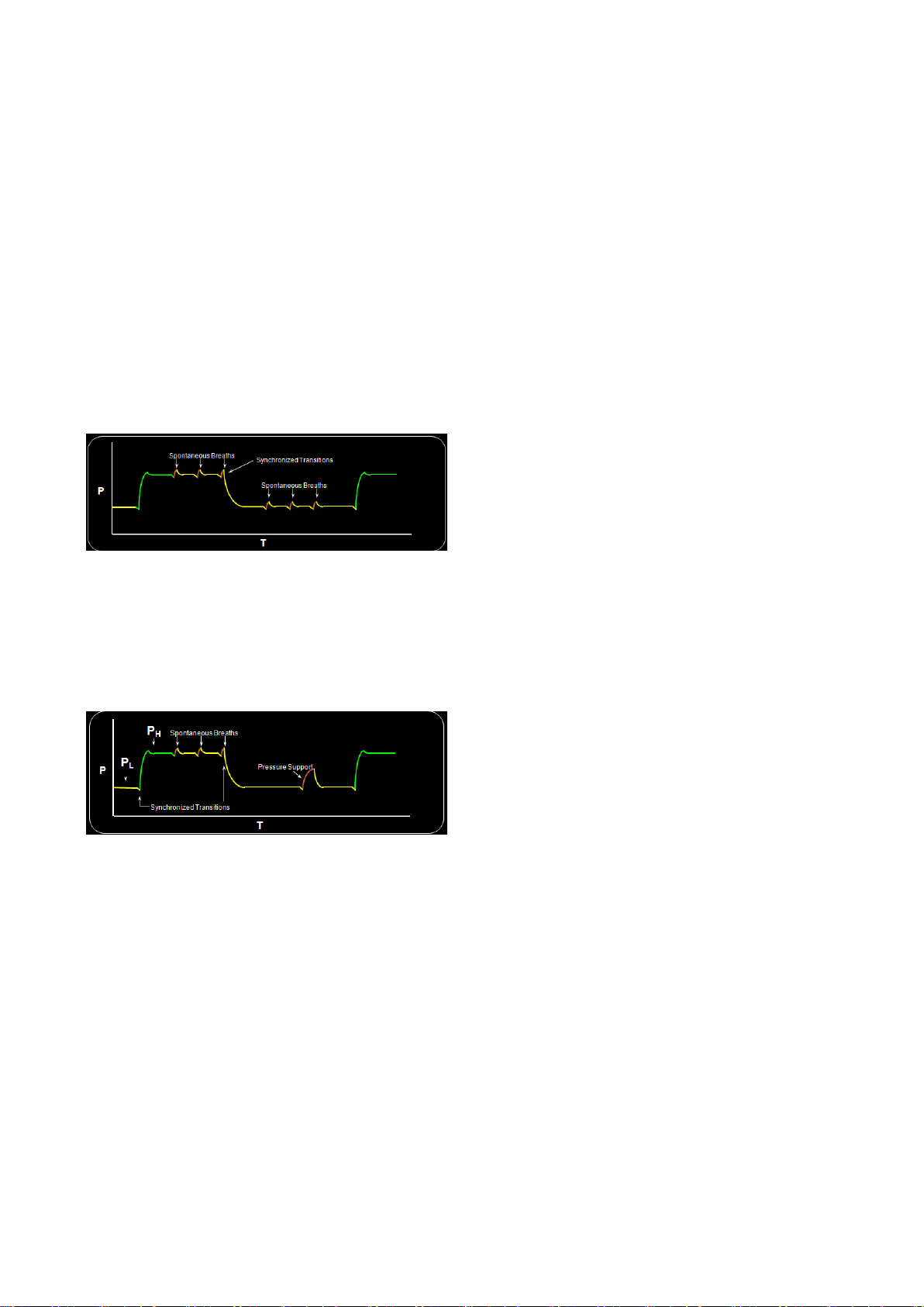
6. Ventilation Mode and Function
Therefore, all mandatory breaths in tBILEVEL mode
are pressure control ventilation. The Transition
interval is short time in before and after of each
transition period. In this interval if the patient
intends to breath, the transition time can be
quickened or slowed according to the breathing
pattern.
Setting items include respiratory rate, PEEP
and PEEP
. Support pressure is additionally
LOW
HIGH
configured using pressure support ventilation.
It is possible to synchronize the transition from
PEEP
cycle. Also at PEEP
to PEEP
HIGH
with the patient’s respiratory
LOW
, the spontaneous breath is
LOW
pressure supported
can be supported at any time, reducing fighting
between the device and patient. Therefore,
frequency of inevitable sedation can be reduced,
resulting in reduction of treatment cost and
quicker recovery of the patient. Also, the patient’s
comfort can be enhanced by providing pressure
support ventilation on all spontaneous breaths.
,
6.10 PRVC
(Pressure Regulated Volume Controlled
Ventilation)
Pressure Regulated Volume Control (PRVC) is a
mechanical ventilation mode based on auto
pressure control. Constant volume is maintained
through target volume and pressure limit setting.
The ventilator delivers a pre-set Tidal Volume. The
pressure is automatically regulated to deliver the
pre-set volume but limited to 1 cmH2O below the
set pressure limit.
In all spontaneous breaths occurring in tBiLEVEL
mode, 1.5 cmH2O pressure supports is
automatically provided. If user wants higher level
of pressure support, pressure support ventilation
can be configured. If the value of support pressure
+ PEEP
is larger than PEEP
LOW
, pressure
HIGH
support ventilation corresponding to the
difference occurring during spontaneous breath in
PEEP
state is provided. This can be seen in the
HIGH
following figure.
When using tBiLEVEL mode, spontaneous breath
PRVC assures a set target minute ventilation to the
patient. The target volume is based upon settings
for Tidal Volume, frequency and inspiration time.
The inspiratory pressure level is constant during
each breath, but automatically adapts in small
increments breath-by-breath to match the
patient’s lung mechanical properties for target
volume delivery.
MV2000[SU:M] Ventilator MEKICS Co., Ltd
42
Page 52
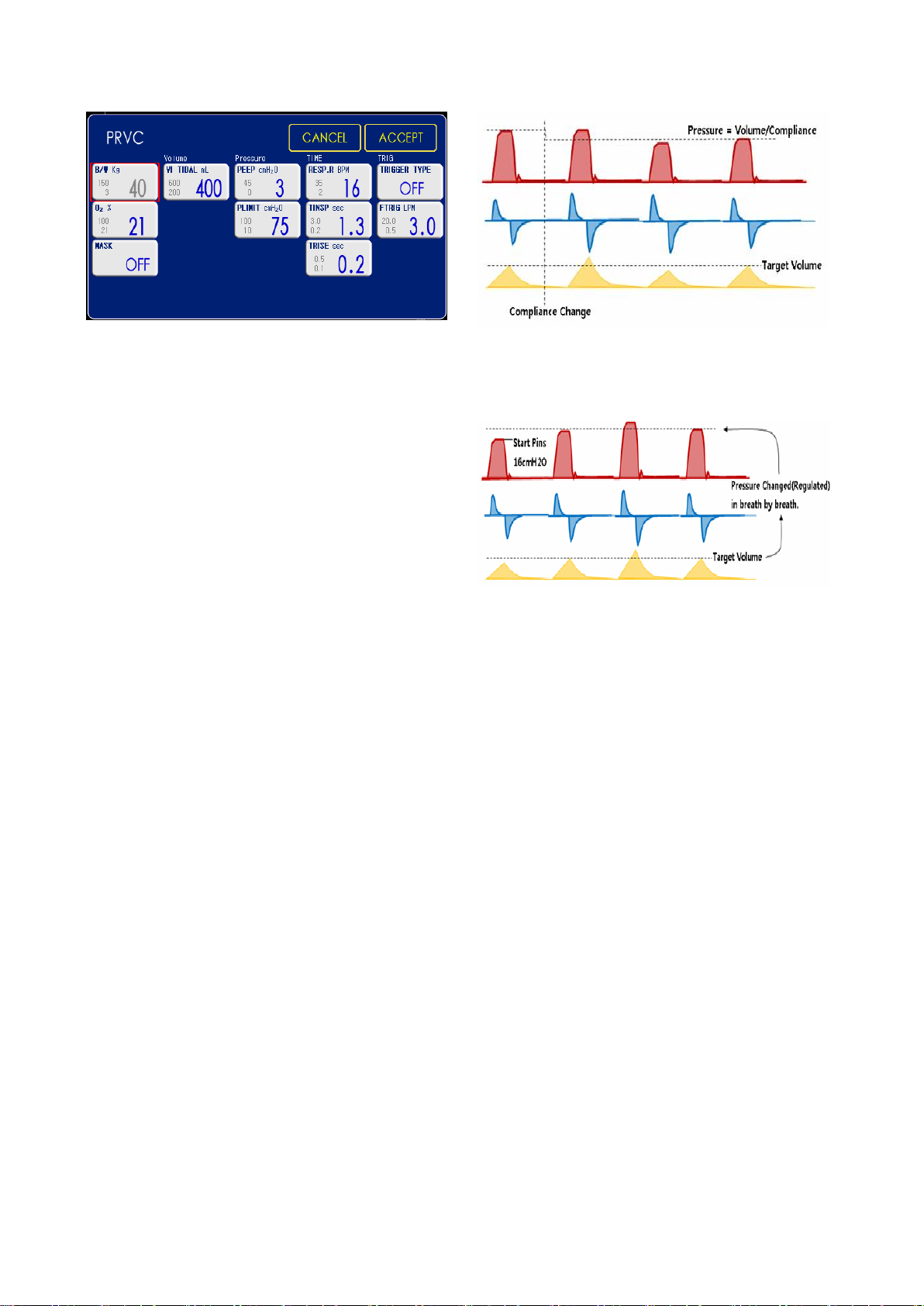
6. Ventilation Mode and Function
The following parameters are configured in PRVC
mode.
1. Tidal Volume(ml)
2. Inspiration Time(sec)
3. Respiratory Rate(b/min)
4. PEEP(cmH
2
O)
5. Oxygen Concentration(%)
6. Inspiration Rise Time(sec)
7. Trigger Flow/Trigger Pressure
8. Trigger Setting(lpm/ cmH
9. Pressure Limit(cmH
2
O)
2
O)
10. Mask Mode(On/Off)
Despite advantages of pressure mode, instability
of not guaranteeing inspiratory volume, caused by
long-term or acute change in patient’s respiratory
status or long-term change in lung compliance, is
removed.
The ventilator delivers configured tidal volume.
Pressure maintained for supply of configured tidal
volume is automatically adjusted within the range
of pressure limit.
The first breath of a start sequence is a volumecontrolled test breath with pressure of 16cmH2O.
The measured pause pressure of this breath is
then used as the pressure level for the following
breath.
During the breathing, the pressure regulated
according to compliance changing of patient.
6.11 O2 Stream
This mode can be used for nasal CPAP and high
flow therapy. This mode controls a microminiature flow along with adjusting O2 flow.
The conventional CPAP must be used with a
humidifier in order to a patient’ breathing air
should be moisture, but O2 Stream flows O2 gas at
the same time with air, the breathing air will be
easy for a patient’s nasal and lung.
O2 Stream supports a positive airway pressure on
the control flow to reduce the dead space at a
patient’s lung.
Peak pressure is limited using Pressure
Limit(P_limit) for safer application to the patient.
MV2000[SU:M] Ventilator MEKICS Co., Ltd
43
Page 53
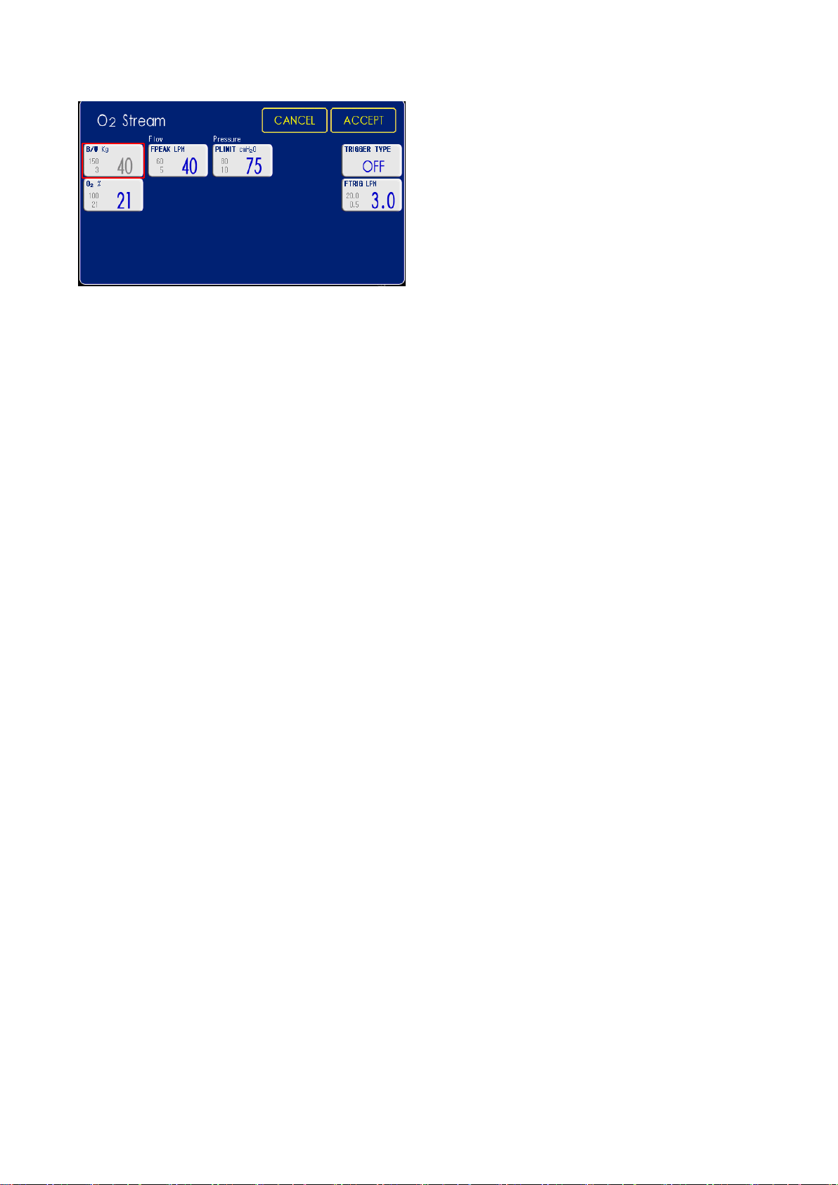
The following parameters are configured in O2
stream mode.
1. Inspiratory Peak Flow(Lpm)
2. Pressure Limit(cmH
2
O)
3. Oxygen Concentration(%)
4. Trigger Flow/Trigger Pressure
5. Trigger Setting(lpm/ cmH
2
O)
6.12 AutoVent
Though it is a single mode, this mode is actively
operated according to the status of the patient
throughout ACV SIMV Spont modes while
guaranteeing minute volume.
Optimal WOB(Work of Breathing) is found in
prescribed respiration per minute. Medical staff
manages the patient using three values
including %MinVol, PEEP and O2. This guideline
includes weaning induction.
If self-breathing of the patient is strong, operation
is conducted as Spont + PS (5cmH2O minimum) +
10 seconds apnea time. The patient’s respiration is
reduced or non-breathing over 10 seconds is
automatically controlled.
Advantages and limitations of AutoVent mode are
as follows.
1. Advantages
1) Patient is managed without transition
between CMV, SIMV, and Spont modes.
2) Since minute volume is guaranteed
3) Based on monitoring result on gas
2. Limitations
1) Since this mode includes a completely
2) Patient management is still required since
3) Since WOB can be increased or optimized
4) Optimization of respiratory gas
6. Ventilation Mode and Function
Convenience of mode management and
simplification of patient information can
be accomplished.
without risks in weaning induction such as
non-breathing, this mode is relatively safe
against non-breathing.
concentration in blood and respiration gas
concentration of the patient, relatively
stable patient management is made
possible through simplified algorithm
for %Vmin, PEEP, and O2 concentration.
different concept than existing modes,
training on the new method is required.
There is a possibility of mistaking this
mode as a universal mode with lack of
training, leading to inappropriate patient
management.
operation becomes unstable by autotriggering.
based on decision of %Vmin, patients
must be managed using new training and
guidelines compared to existing modes.
concentration and gas concentration in
blood through monitoring can be difficult
compared to general modes (limitation in
adaptation to individual conditions of
patients).
MV2000[SU:M] Ventilator MEKICS Co., Ltd
44
Page 54
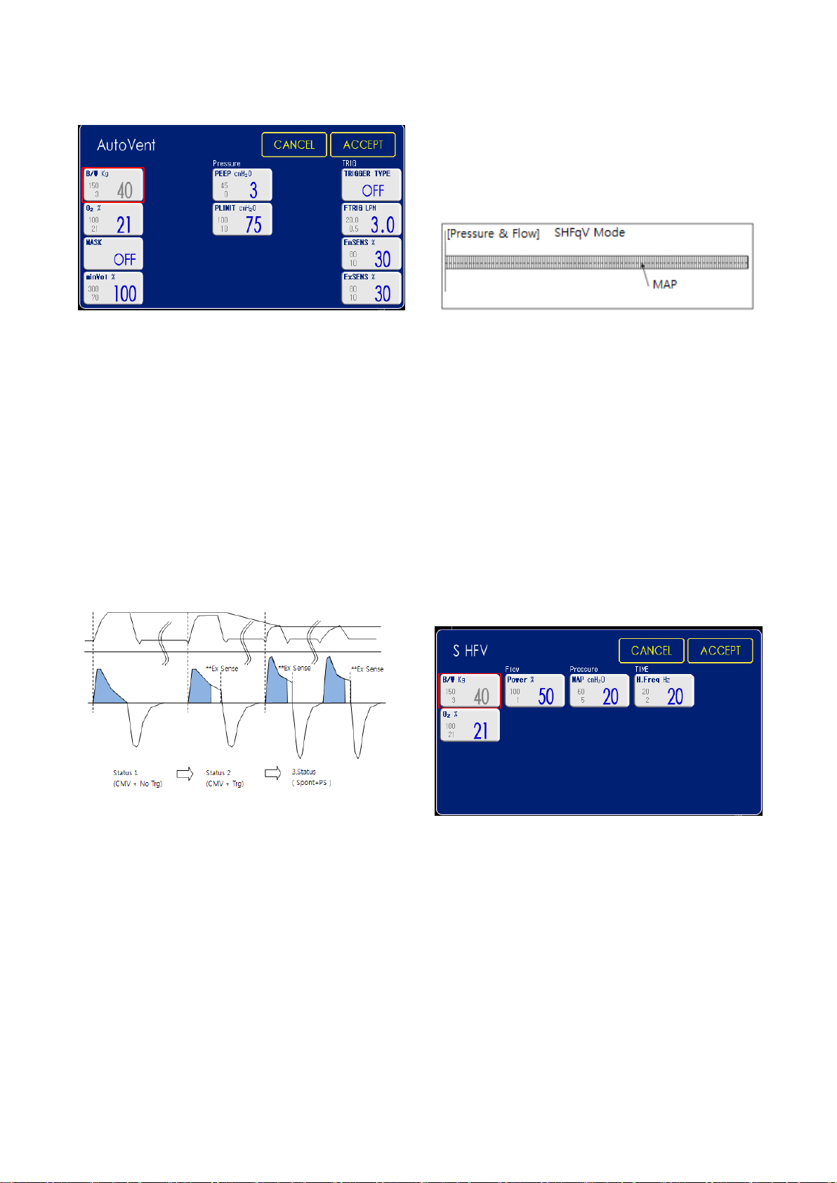
6. Ventilation Mode and Function
The following parameters are configured in
AutoVent mode.
1. PEEP(cmH
2
O)
2. Trigger Flow/Trigger Pressure
3. Trigger Setting(lpm/ cmH
2
O)
4. Oxygen Concentration(%)
5. Pressure Limit(cmH
2
O)
6. Inspiratory Trigger Sensitivity(%)
7. Expiratory Trigger Sensitivity(%)
8. minVol(%)
9. Mask Mode(%)
The adult case sets4~8Hz(240~480bpm) and
Infant case sets 10~15Hz(600~900bpm). Select
appropriate setting according to patient condition
and clinician’s decision.
According to the patient’ lung, you select the MAP.
If you increase the amplitude of the Pman and
Pmin, Paw should be greater than the amplitude
of 1/2.
Power doesn’t have the unit and determine the
minimum and maximum power. When the power
increases, the amplitude of the pressure and flow
rate is increased. But the amplitude of the
pressure increase, if Paw is low, the amplitude will
be limited by Paw.
6.13 SHFV (Single High Frequency
Ventilation)
High Frequency Ventilation was developed with
the ideal of providing “gentle breathing” for every
patient from newborn infants to seniors.
This mode is high frequency ventilation mode with
single frequency.
Frequency range: 2 ~ 20Hz.
The following parameters are configured in SHFV
mode.
1. Power(%)
2. MAP(cmH
2
O)
3. Frequency Range(Hz)
4. Oxygen Concentration(%)
6.14 DHFV (Dual High Frequency
Ventilation)
MV2000[SU:M] Ventilator MEKICS Co., Ltd
45
Page 55
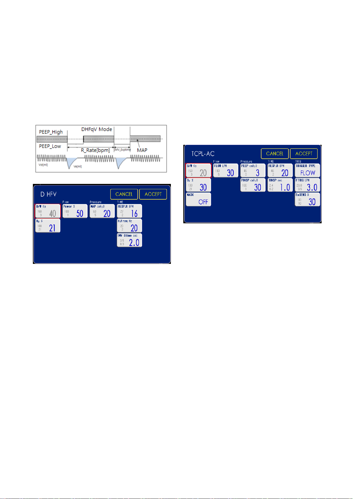
6. Ventilation Mode and Function
Insufficient ventilation volume of SHFV mode can
be supplemented intermittently using exhalation
time.
During expiratory time, it is available measuring
EtCO2. Increasing CO2 exhalation at insufficient
ventilation of Single HFV.
The volume of gas delivered to the patient in this
TCPL varies depending on pulmonary mechanics
such as compliance of stiffness of the lungs.
At low compliance(‘stiff lungs’) such as occurs
early in the course of respiratory distress
syndrome(RDS), a given pressure generates lower
tidal volume.
The following parameters are configured in DHFV
mode.
1. Power(%)
2. MAP(cmH
2
O)
3. Respiratory Rate(b/min)
4. Frequency Range(Hz)
5. IMV time(sec)
6. Oxygen Concentration(%)
6.15 TCPL-AC
(Time Cycled Pressure Limited-Assist
Control)
A peak inspiratory pressures is set by the operator,
and during inspiration gas flow is delivered to
The following parameters are configured in TCPLAC mode.
1. Flow(lpm)
2. Respiratory Rate(b/min)
3. PEEP(cmH
2
O)
4. Oxygen Concentration(%)
5. Inspiratory Pressure(cmH
O)
2
6. Inspiratory Time(sec)
7. Inspiratory Trigger Sensitivity(%)
8. Trigger Flow/ Trigger Pressure
9. Trigger Setting(lpm/ cmH
2
O)
10. Mask Mode(On/Off)
The following case shows pressure and flow
changes according to time when high flow and
low compliance.
achieve that set pressure, hence the term
pressure-limited(PL).
MV2000[SU:M] Ventilator MEKICS Co., Ltd
46
Page 56
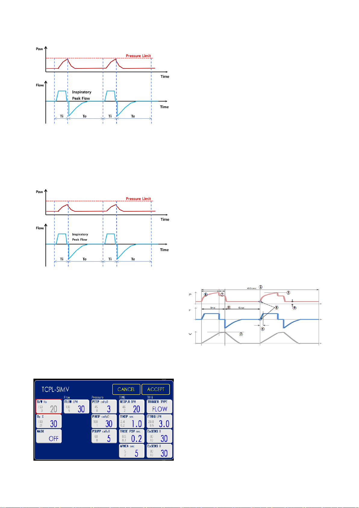
6. Ventilation Mode and Function
The following parameters are configured in TCPLSIMV mode.
1. Flow(lpm)
2. Respiratory Rate(b/min)
The following case shows pressure and flow
changes according to time when low flow and
high compliance. It can’t be to reach the
pressure limit.
6.16 TCPL-SIMV
3. PEEP(cmH
2
O)
4. Oxygen Concentration(%)
5. Inspiratory Pressure(cmH
O)
2
6. Inspiratory Time(sec)
7. Inspiratory Trigger Sensitivity(%)
8. Expiratory Trigger Sensitivity(%)
9. Trigger Flow/ Trigger Pressure
10. Trigger Setting(lpm/ cmH
11. Pressure Support(cmH
12. Trise Pressure Support(cmH
2
O)
2
O)
2
O)
13. Apnea(sec)
14. Mask Mode(On/Off)
6.17 Ventilation Parameter Outline
When ventilation mode is selected, parameters
related to the configured ventilation mode are
displayed on the screen. The following parameters
are related to all ventilation modes.
(Time Cycled Pressure LimitedSynchronized Intermittent Mandatory
Ventilation)
TCPL-SIMV mode is similar to one the TCPL-AC
mode and the mode assist the patient’s
spontaneous breathing.
1. Respiratory Rate (RR)
Respiratory rate is used to calculate the number
of mechanical respirations or target volume
(b/min).
2. Tidal Volume (VT)
Volume per respiration or target volume (mL)
3. Minute Volume (Vmin)
Volume per minute or target minute volume
47
MV2000[SU:M] Ventilator MEKICS Co., Ltd
Page 57

4. Inspiratory Pressure Level
5. Inspiratory Rise Time
Arrival time from the start of each respiration to
flow / pressure peak
6. I:E Ratio (I:E)
(Inspiration time + Pause time): Expiration time
7. Inspiration Time
Delivered time to patient of flow or pressure
8. Pause Time
Temporary pause time during which flow or
6. Ventilation Mode and Function
pressure is halted without delivery
9. Trigger Flow/Trigger Pressure
- Trigger Flow is that the amount of bias flow
can gradually be reduced for induction of
ventilation.
- Trigger Pressure is that pressure must be
created below the configured PEEP through
inhalation of excessive bias flow to induce
ventilation.
10. PEEP
Positive end expiratory pressure (cmH2O)
MV2000[SU:M] Ventilator MEKICS Co., Ltd
48
Page 58
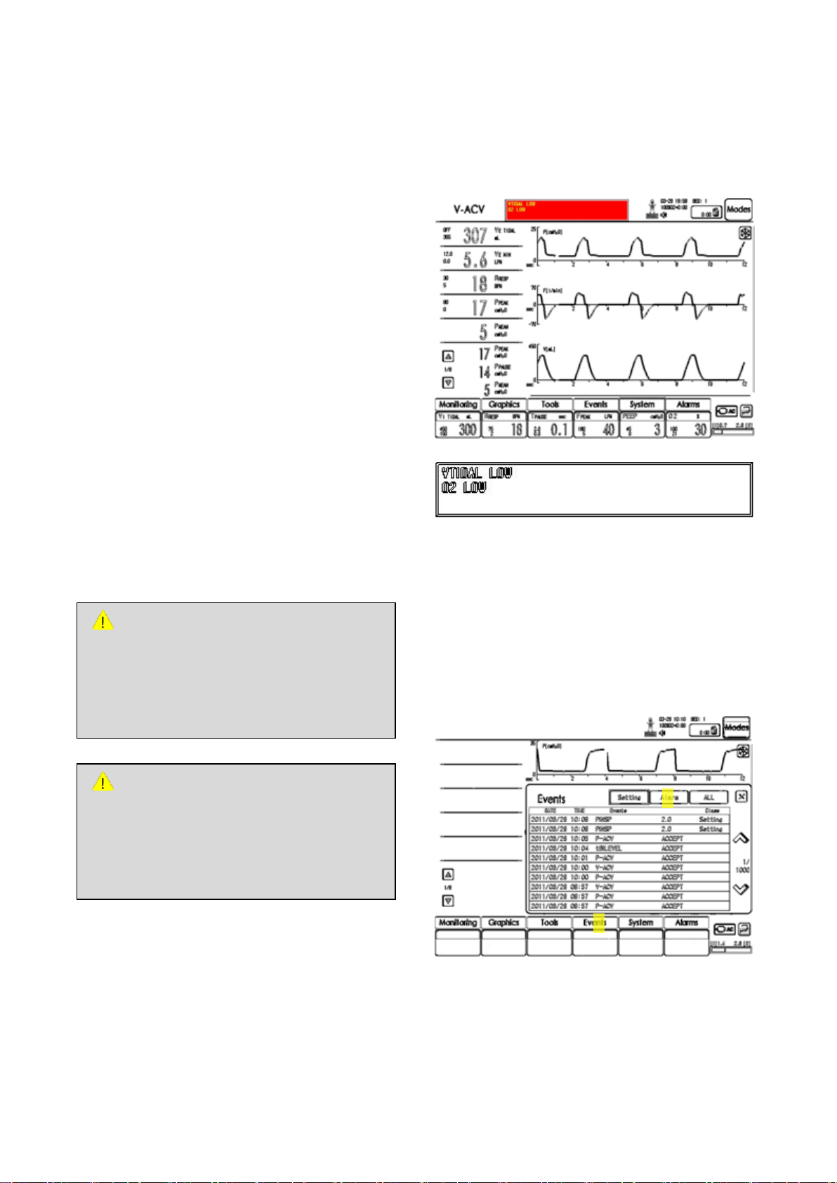
7. Alarm
ATTENTION
If an alarm occurs, measures must be taken
by a medical professional with exp erience in
ventilator treatment or an individual trained
with MV2000[SU:M] ventilator.
WARNING
Potential risk can be increased if default
alarm values applied to ventilators or other
similar devices used in same place differ
from each other.
②
①
7. Alarm
7.1 Introduction
MV2000[SU:M] ventilator includes an alarm system
for the patient’s safety. In case of the following
problems, alarm sound is created with screen
display.
- Breathing problem, ex: Apnea
- Power problem, ex: Battery mode
- Gas problem, ex: Reduced gas pressure
This Chapter describes general response method,
sequence of alarm setting (refer to Chapter 4
Operation Method for details), range of alarm
setting, and list.
Refer to Chapter 8 Alarm Message for details on
causes and solutions to all alarms.
7.1.1 Alarm Display
If an alarm occurs, it is displayed on the screen
with a message as follows.
1) Alarm message window flickers and displays
the cause of alarm.
2) Measurement value window corresponding to
MV2000[SU:M] Ventilator MEKICS Co., Ltd
the alarm will flicker.
7.2 Alarm Removal
7.2.1 View Current Alarms
More than one alarm can be checked through
alarm message displayed on top of the screen. To
check more alarms,
49
Page 59
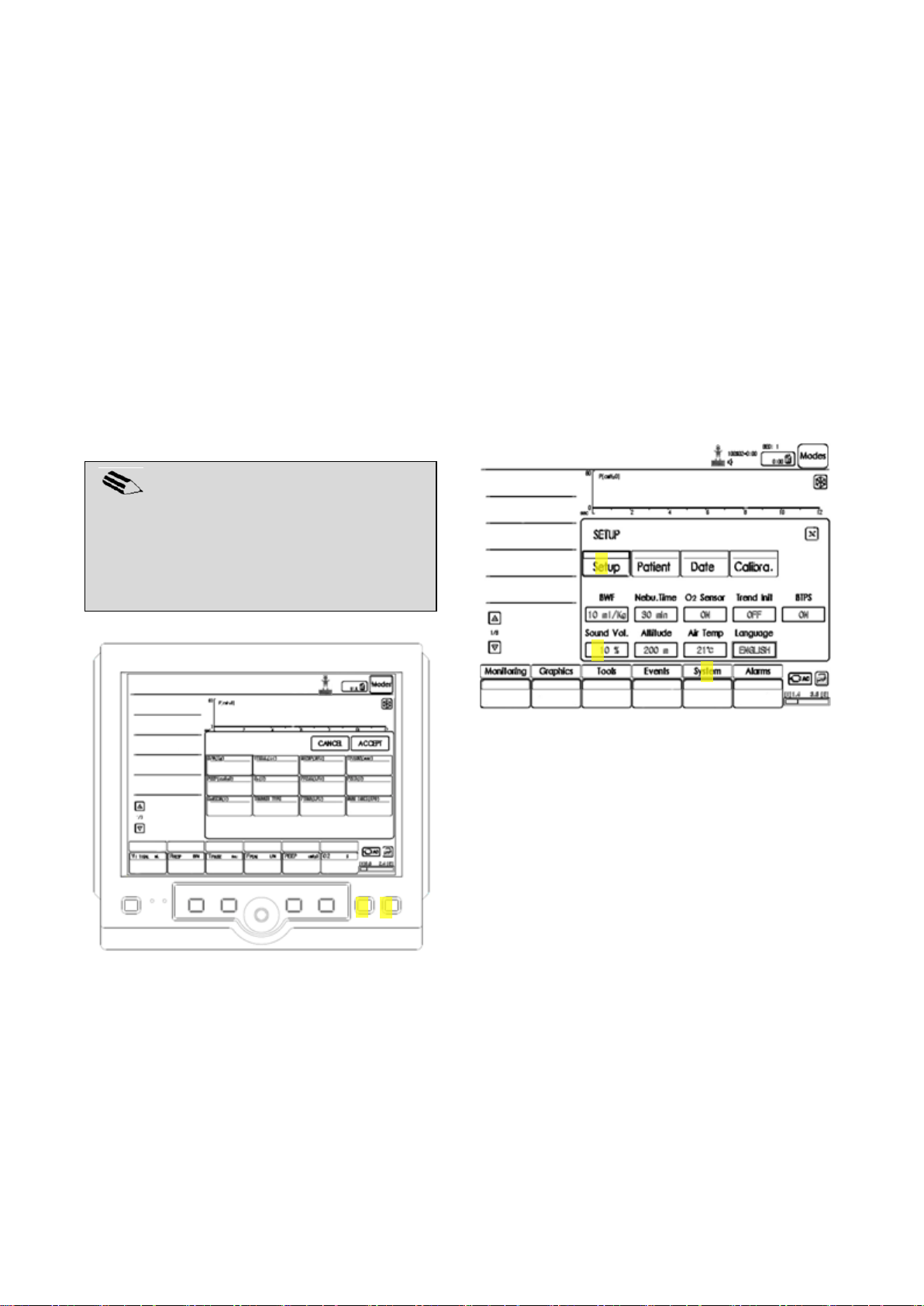
7. Alarm
NOTE
Alarm sound can be muted without settling
current alarms. However, sound may
operate intermittently depending on the
situation.
② ① ② ① ③
1) Choose Events menu on bottom of the screen.
2) Select Alarms among sub menu of Events to
see all recent alarms.
7.2.2 Alarm Removal
Current alarm messages and alarm actions can be
canceled by pushing Alarm Reset button among
fixed keys at the bottom of the monitor.
Also, alarm action is automatically canceled if the
alarm condition is settled.
7.2.3 Pausing Alarm Sound
If Alarm Silence button is pushed among fixed
keys at the bottom of the monitor,
- Current alarms become silenced or muted for
two minutes.
- Bell icon appears on the message window
with remaining time for mute.
- Sound is muted for two minutes every time
Alarm Silence button is pushed.
7.2.4 Alarm Sound Volume Control
1) Alarm Silence (2 min)
2) Alarm Reset
1) Select System button among menu buttons
located at the bottom of user interface.
2) Select Setup in the System menu.
3) Activate sound volume by touching Sound Vol.
Adjust the volume of alarm sound. Once
adjustment is complete, touch again to
deactivate the window.
MV2000[SU:M] Ventilator MEKICS Co., Ltd
50
Page 60

7.3 Alarm Setting
Item
Range
Default
Unit
Step
VE TIDAL HIGH
OFF,
5~2500
OFF
mL
10
VE TIDAL LOW
0~2500
50
mL
10
VE MIN HIGH
0.1~50
12
LPM
0.1
VE MIN LOW
0.0~49.9
1.2
LPM
0.1
R RESP HIGH
3~180
30
BPM
1
R RESP LOW
2~179
5
BPM
1
P PEAK HIGH
1~120
80
cmH2O
1
P PEAK LOW
0~119
0
cmH2O
1
O2 HIGH
OFF,
1~100
OFF % 1
O2 LOW
0~100
20 % 1
AIR LEAK
OFF,
50~500
300
mL
10
Apnea
2~60
20
sec
1
SpO2 HIGH
(optional)
OFF,
52~99
OFF % 1
SpO2 LOW
(optional)
OFF,
51~99
81 % 1
PR HIGH
(optional)
30~250
150
BPM
5
PR LOW
(optional)
25~245
50
BPM
5
EtCO2 HIGH
(optional)
0~10.0
6.0
mmHg
0.1
EtCO2 LOW
(optional)
OFF,
0~9.9
OFF
mmHg
0.1
INS HIGH
(optional)
0~10.0
3.0
mmHg
0.1
INS LOW
(optional)
OFF,
0~9.9
OFF
mmHg
0.1
RESP HIGH
(optional)
3~150
30
BPM
1
RESP LOW
(optional)
2~149
5
BPM
1
This Section explains alarm screen display, alarm
setting
7.3.1 Alarm Screen Display
Configured alarms values are displayed on the left
side of the screen and in measurement value
window at the bottom. Among displayed alarm
values, value above is the upper limit and value
7. Alarm
below is the lower limit.
7.3.2 Alarm Setting
Select Alarms among menu at the bottom of the
screen when configuring alarm values. A new
menu called Alarm Set appears. This menu can be
used to configure alarms.
MV2000[SU:M] Ventilator MEKICS Co., Ltd
51
Page 61
8. Alarm Message
CAUTION
When the ventilator is in operation, do not
raise or separate expiratory cassette.
However, it may be separated in stand-by
mode.
WARNING
When conducting an act that can bring risks
to the patient such as replacement of O
2
cell,
always separate the ventilator from the
patient.
NOTE
Contact service assistant for most of
technical errors.
8. Alarm Message
8.1 Introduction
This Chapter describes alarms and measures on
each alarm message.
MV2000[SU:M] Ventilator MEKICS Co., Ltd
52
Page 62

8.2 Alarm and Error Message
No
Alarm
Message
Occurrence
(Immediate /
Separate)
Criteria
1
Apnea
After apnea
time
Only operated in Spont mode
If there is no respiration within configured apnea time.
2
Backup Mode
After apnea
time
Only operated in Spont mode
Apnea occurs to notify backup mode operation.
Alarm continues to sound during VENT (VACV/PACV mode)
operation(Backup mode operates if Apnea mode is operated in
Spont mode)
Mode is switched to Spont mode in case of two spontaneous
breaths in 10 seconds
3
Obstruct
Immediate
When inspiration outlet or expiration inlet are blocked
4
Expiratory
Minute
Volume High
One minute
after Vent
operation
If configured value or default alarm limit is exceeded
If there is an increase in the patient’s effort for breathing
If self-triggering (auto cycling) of the ventilator occurs
If alarm setting is inappropriate
This alarm is operated one minute after Vent mode operation.
5
Expiratory
Minute
Volume Low
One minute
after Vent
operation
If configured value or default alarm limit is exceeded
If there is little effort by the patient to breathe
If there is leakage around cuff
If there is leakage in the patient’s tube line
If alarm setting is inappropriate
This alarm is operated one minute after Vent mode operation.
6
Pressure High
Immediate
If high pressure exceeds setting or default alarm limit
If tube line is twisted or blocked
If a mucus or secretion blocks endotracheal tube or airway
If the patient coughs or fights with ventilator
If inspiratory flow is extremely high
If alarm setting is inappropriate
If expiratory filter is blocked
When an alarm message occurs, check current mode and settle the problem immediately.
8. Alarm Message
MV2000[SU:M] Ventilator MEKICS Co., Ltd
53
Page 63

8. Alarm Message
No
Alarm
Message
Occurrence
(Immediate /
Separate)
Criteria
7
Pressure Low
Immediate
If low pressure exceeds setting or default alarm limit
If there is leakage around cuff
If there is leakage in the patient’s tube line
If alarm setting is inappropriate
Spontaneous breathing is not applied
8
Respiratory
Rate High
After taking
mean value on
four respirations
If respiratory rate is too high
If auto triggering occurs
If higher than setting alarm limit
9
Respiratory
Rate Low
After taking
mean value on
four respirations
If respiratory rate is too low
If trigger sensitivity setting is inappropriate
If lower than setting alarm limit
10
Tidal Volume
High
Immediate
If setting or default alarm limit is exceeded
If there is an increase in the patient’s effort to breathe
If self-triggering (auto cycling) of the ventilator occurs
If alarm setting is inappropriate
11
Tidal Volume
Low
After taking
mean value on
Vtidal of three
respirations
If setting or default alarm limit is exceeded
If there is leakage around cuff
If there is leakage in the patient’s tube line
If alarm setting is inappropriate
Spontaneous breathing is not applied
12
O2 High
One minute after
Vent mode or O2
alarm setting
If higher than setting alarm limit
13
O2 Low
One minute after
Vent mode or O2
alarm setting
If lower than setting alarm limit
14
Gas Supply
Pressure Low
Immediate
In case supplied gas pressure is lower than 3psi or impurities are
included in inlet filter
15
Circuit Open
Immediate
If inspiratory flow is above 8Lpm and exp pressure below 3cmH2O
is maintained over 10 seconds, or over 8L is supplied
If circuit is easily opened or PEEP bundle
16
Air Gas Fail
Immediate
If tank pressure is over 10 seconds and under 10psi
After failure of air supply gas, gas supply is checked every two
minutes for automatic recovery
17
O2 Gas Fail
Immediate
If tank pressure is over 10 seconds and under 10psi
After failure of O2 supply gas, gas supply is checked every two
minutes for automatic recovery
MV2000[SU:M] Ventilator MEKICS Co., Ltd
54
Page 64

8. Alarm Message
No
Alarm
Message
Occurrence
(Immediate /
Separate)
Criteria
18
Circuit
Leakage
After three
consecutive
respirations
Linked to leakage volume (mL) configured by user
Used when the difference between insp volume and exp volume is
larger than leakage volume configured by user
Circuit leakage alarm occurs if difference between insp and exp
volumes occurs during three consecutive respirations
Note: NIV and Spont mode do not apply.
19
Vent Inop.
Immediate
If air gas and O2 gas are not supplied and tank pressure is under
5psi.
If battery usage is under 5 minutes
If there is no respiration during time for three respirations in Vent
mode
Note: This may occur once during initial operation of product.
20
Low Battery
Voltage
Immediate
Remaining battery is 5 minutes
21
O2 Cell
failure
Immediate
If O2 is detected below 18%
If O2 cell fails(However, screen only displays 21% or above).
MV2000[SU:M] Ventilator MEKICS Co., Ltd
55
Page 65
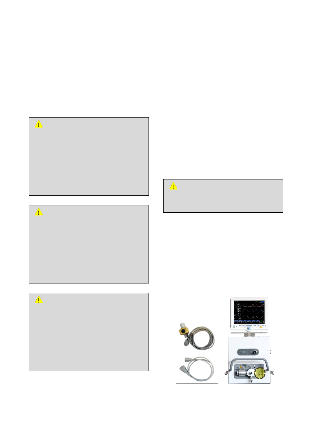
9. Supplementary Devices
WARNING
Only use CO2 components certified by our
company.
ATTENTION
- Since use of soft tube with extremely
high compliance can affect functions of
the ventilator, use tubes supplied by our
company if possible.
- Supplementary accessories connected
to the patient’s tube can influence
patient pressure.
CAUTION
- Since water can be formed in the tube
when heating type humidifier is used,
water trap must be connected to
expiratory tube line.
- During operation, water trap must be
checked frequently and emptied
accordingly.
WARNING
- Heating type humidifier must be turned
off when using nebulizer. Failure to turn
off may influence the particle size of
absorption drug.
- Unexpected increase in gas temperature
may result from use of unauthorized
humidifier.
9. Supplementary Devices
9.1 MEKICS Humidifier VH-2600
Use of heating humidifier in treatment of patients
can be beneficial.
Refer to user manual by the corresponding
manufacturer for structure and usage of humidifier.
9.2 EtCO2 (Option)
(End Tidal CO2 Concentration)
EtCO2 sensor displays expiratory end CO2
concentration as a graph.
As a device that consecutively measures EtCO2
concentration during expiration to predict pCO2
(CO2 concentration in blood), the sensor is an
important means to monitor appropriate
inspiration and expiration states. Also, since the
sensor is a means to determine respiratory
diseases such as asthma based on extraction of
various parameters from capnograph wave, it is
also used for diagnosis.
9.2.1 EtCO2 Connection Method
1) Connect EtCO
which EtCO2 label is attached on the right side
of MV2000[SU:M] ventilator.
2) Connect the EtCO
3) Measurement values are displayed by selecting
EtCO2 graph from Graph Selection menu.
sensor cable to the socket on
2
sensor to the patient.
2
MV2000[SU:M] Ventilator MEKICS Co., Ltd
56
Page 66

9.2.2 EtCO2 Calibration
CAUTION
- Do not use the sensor to patients with
allergic symptoms to SpO2 sensor.
- Immediately remove the sensor if the
patient calls for discomfort.
WARNING
- Only use SpO
2
sensor certified by
MEKICS. If a different product is used,
there may be a problem in performance.
- Only use SpO
2
sensor certified by
MEKICS. If a different product is used,
there may be a problem in performance.
- Sensor should not be used on parts with
artery catheter or vein syringe.
- Do not use damaged SpO
2
sensor or
optical device.
- Since the sensor is not waterproof, do
not place in water and solvent or clean
excessively.
- Do not sterilize the sensor with ultraviolet
ray, direct sunlight, steam or hydrogen
peroxide.
1) Select System in the menu at the bottom of
user interface.
2) Select Calib. menu among System menu.
3) Perform EtCO
calibration in Calib. menu.
2
9.3 SpO2 (Option)
(Pulse Oximeter Oxygen Saturation)
Oxygen saturation shows the degree of
concentration of hemoglobin that transports
oxygen in the artery. That is, it displays the degree
of currently transported amount compared to
oxygen transportable by hemoglobin as a
9. Supplementary Devices
percentage. It does not show the amount of
carboxyhemoglobin or methemoglobin
hemoglobin from hemoglobin disorder.
MV2000[SU:M] Ventilator MEKICS Co., Ltd
57
Page 67
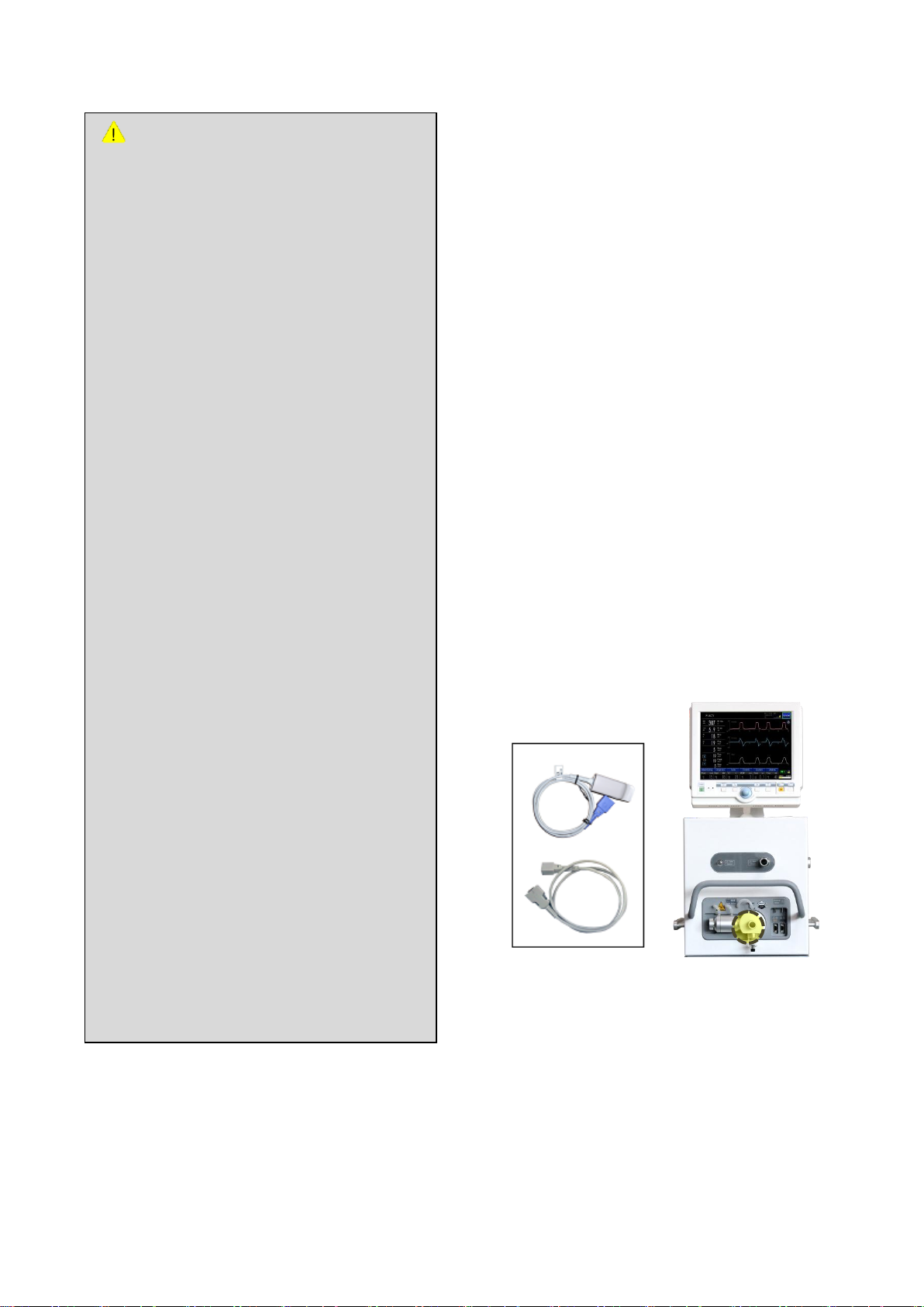
9. Supplementary Devices
ATTENTION
Inaccurate values and waves can result as
below if sensor is used incorrectly.
- When sensor not certified by MEKICS is
used or sensor is used incorrectly
- Functional disorder in hemoglobin
- When sensor is excessively exposed to
medical light (especially xenon light),
bilirubin light, fluorescent light, infrared
heating device, or direct sunlight
- Excessive movement by the patient
- Use of high frequency electric surgical
instrument or cardiac resuscitator
- Pulse of venous blood
- Measured at a spot where blood pressure
is measured, pressure bandage is used,
artery catheter is used, or sensor is used
inside blood vessel
- Measured at a spot where blood pressure
is measured, pressure bandage is used,
artery catheter is used, or sensor is used
inside blood vessel
- When there is arterial occlusion nearby
the sensor
- When the patient is experiencing cardiac
arrest or shock
Heart rate may be inaccurate in the following
situations.
- When sensor is tightened too much
- When sensor receives excessive medical
light, bilirubin light or sunlight
- When measured with pressure bandage
or at a spot pressured by cuffs
order to prevent excessive light, follow the
instructions for use. Use opaque substances to
prevent the sensor from being exposed to external
light sources. Computed values may become
inaccurate if surrounding environment is too
bright.
Since movement of the patient can cause
problems, check whether the sensor is being
operated safely. Adhesive-type sensor can be used
to reduce measurement errors from patient’s
movement.
9.3.1 SpO2 Connection Method
1. Connect SpO
sensor cable to the socket on
2
which SpO2 label is attached on the right side
of MV2000[SU:M] ventilator.
2. Place a finger on the SpO
3. Wait for a moment until SpO
sensor.
2
measurement
2
values are displayed as a graph.
The sensor may show performance problems
when exposed to excessive medical light
(especially xenon light), bilirubin light, fluorescent
light, infrared heating device, or direct sunlight. In
MV2000[SU:M] Ventilator MEKICS Co., Ltd
58
Page 68
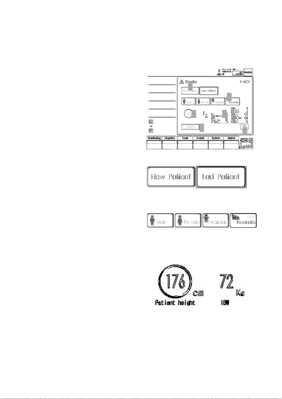
10. Initial Screen Configuration
①
② ③ ④
⑤
⑥
10. Initial Screen Configuration
10.1 Introduction
When MV2000[SU:M] ventilator is operated, it is
operated in stand-by mode. User can configure
and change the following default values.
- Patient (New or Last)
- Patient Range (Adult or Neonate)
- Height and Body Weight of Patient
- Ventilation Mode (Including Setting
Parameters)
10.2 Start-Up Configuration
Initial screen of MV2000[SU:M] is as follows.
1. Add a new patient or load recent patient setting.
2. Select appropriate patient range according to
age and gender.
3. If height of the patient is decided according to
age and gender, PBW (predicted body weight) is
automatically calculated.
59
MV2000[SU:M] Ventilator MEKICS Co., Ltd
Page 69
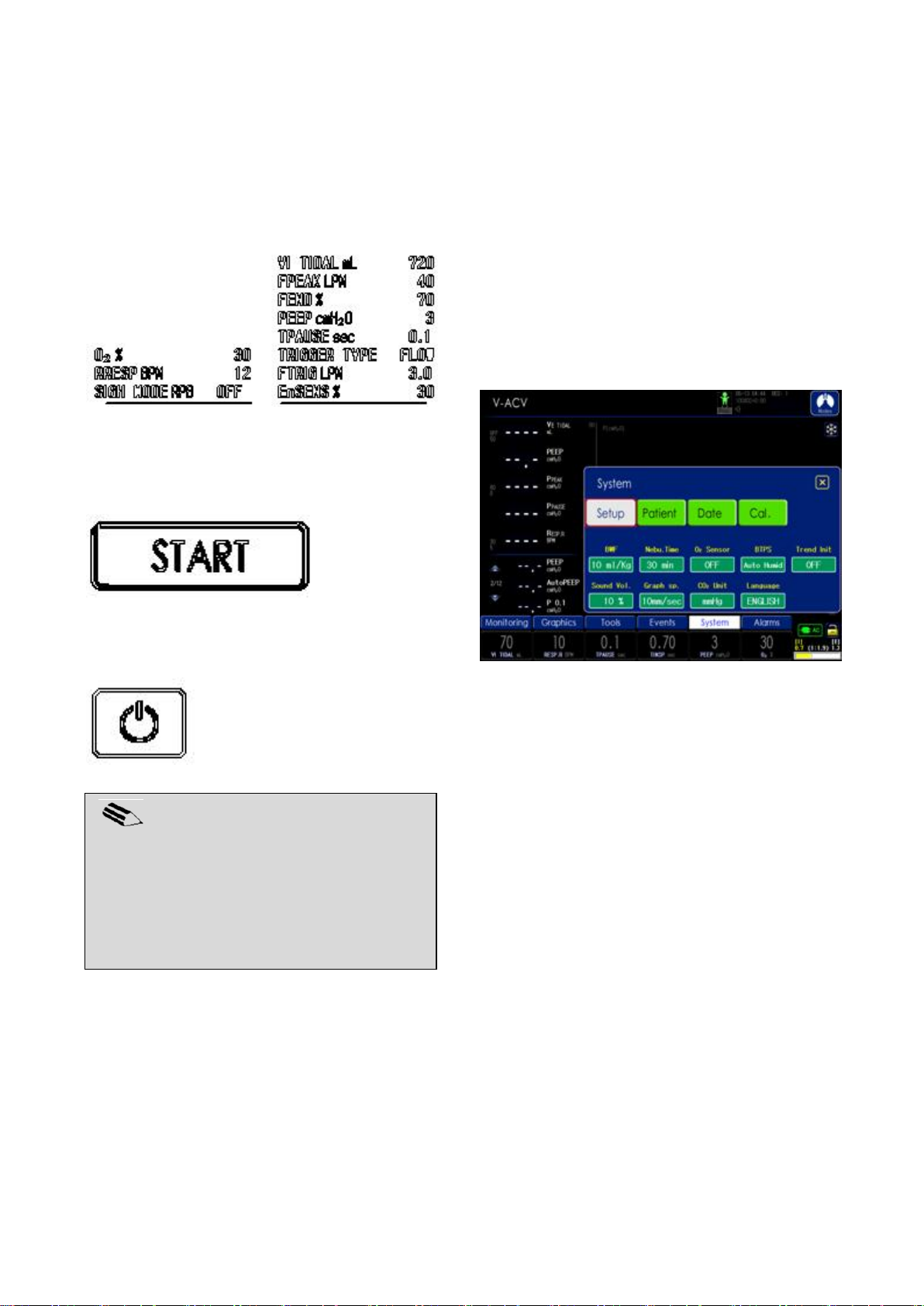
10. Initial Screen Configuration
NOTE
In the initial standby screen, various menu
at the bottom can also be used in addition to
setting patient information and parameters.
Matters required for ventilation can be
configured through System menu.
4. Touch measurement screen to move to mode
setting screen and configure related parameters.
Touch Modes button on the top right corner to
change ventilation mode and configure
parameters.
5. Ventilation begins after configuring all
parameters with patient information and
touching Start button.
10.3 System Setting
System menu is composed of Setup menu that
configures operating conditions of the ventilator,
Patient menu that configures patient information,
Date menu that decides date and time, and
Calibration menu that configures various
calibrations.
10.3.1 Setup
6. Touch the following button to turn the power
Off.
MV2000[SU:M] Ventilator MEKICS Co., Ltd
The following parameters are configured in Setup
menu.
1. BWF
- Configure air volume (mL) per Kg of the
patient’s body weight (B/W).
- Range: 5 ~ 15 mL/kg
2. Nebulizer Time
- Configure usage time of nebulizer.
- Range: 10 ~ 180 min
3. O2 Sensor
- Configure the use of O2 cell, whether to
enable or disable the sensor.
- Enable: O2 gas is used when O2 cell is normal.
- Disable: This is when there is no O2 gas,
lifespan of O2 cell has expired, or O2 cell can
not be used for a different reason. There is no
influence on supply of O2 gas.
4 Trend Init
60
Page 70
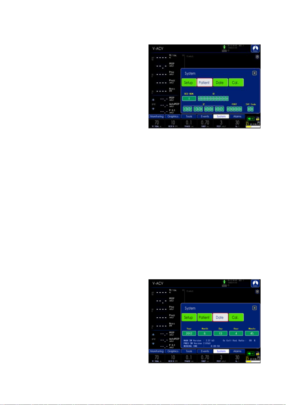
10. Initial Screen Configuration
- Initialize trend data.
5. BTPS
- BTPS is an abbreviation of "Body Temperature
and Pressure Saturated with Water Vapor" and
refers to the state in which physical factors
that influence air volume inside body are
taken into consideration. This function
compensates for volume of air supplied,
considering difference between body
temperature and external temperature with
altitude above sea level.
- Range
OFF: BTPS function is turned OFF.
Auto DRY: Selected if using without humidifier.
Auto Humid: Selected if using with humidifier.
6. Sound Vol.
- Decide alarm sound volume for the ventilator.
- Range: 10 ~ 100 %
7. Graph speed
- Configure waveform graph sweep speed.
- Settings: x1, x2, x4, x8, x16
8. CO2 Unit
- Configure CO
- Settings: % or mmHg
9. Language
Unit.
2
10.3.2 Patient
Patient information is entered in Patient menu,
and the following parameters are configured.
Refer to ‘Chapter 4 Operation Method’ for details.
1. BED Num
- Designate patient’s bed number.
2. ID
- Input patient’s ID number.
3. IP
- Input IP address for external connection using
LAN.
4. PORT
- Input port number for external connection
using LAN.
5. PASSWORD
- Configure password (77) for IP and port input.
10.3.3 Date
- Configure the language to be used.
- The supported language is English, Russian,
Spanish and Chinese.
MV2000[SU:M] Ventilator MEKICS Co., Ltd
61
Page 71
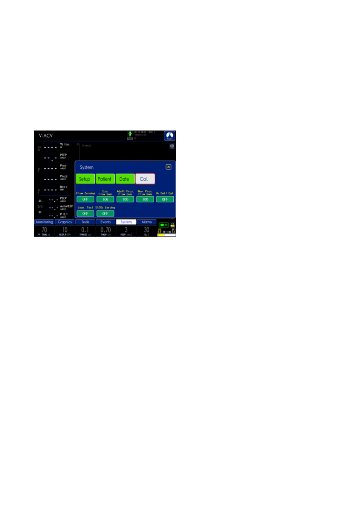
Ventilator’s date is configured in Date menu.
MAIN and PNEU SW version, operation time of
ventilator, and remaining O2 % are displayed.
Date configuration sequence is Year, Month, Day,
Hour and Minute.
10.3.4 Calibration
10. Initial Screen Configuration
In Calibration menu, sensors used in
MV2000[SU:M] ventilator are calibrated. Refer to
‘Chapter 4 Operation Method’ for details.
MV2000[SU:M] Ventilator MEKICS Co., Ltd
62
Page 72

11. Technical Specification
11. Technical Specification
11.1 System
11.1.1 General
MV2000[SU:M] ventilator selected and acquired
the following international standards.
Standards
- EN60601-1:1990
- EN60601-1-1:2001
(Electromechanical Safety)
- EN60601-1-2:2001
(Electromagnetic Compatibility Requirement
and tests)
- IEC60601-2-12:2001
(Particular requirements for the safety of lung
ventilators for medical use)
Electromagnetic compatibility (EMC)
According IEC60601-2, 2nd Edition
11.1.2 Operating Conditions
- Operating Temperature Range
: 10 to 40 ℃ (50~104℉)
- Operating Atmospheric Pressure
: 700 to 1060 mbar (10.2 ~15.4psi)
- Operating Altitude
: -443~ 3048 m (-1350~ 10,000ft)
- Relative humidity
: 10 to 90%
11.1.3 Non-operating Conditions
- Storage temperature
: -15 to 50 ℃
- Storage relative humidity
: 10 to 90%
- Storage Atmospheric Pressure
: 500 to 1060 mbar (7.3 ~15.4psi)
- Storage Altitude
: Up to 6560m (20,000ft)
11.1.4 Power Supply
- AC input voltage
: 100-120 VAC, 10A, 50/60Hz
: 200-240 VAC, 5A, 50/60Hz
- AC input FUSE Rating
: 250V / 6.3A
- Power consumption
: 84W max
- External DC input voltage
: 12V/7A Pb battery
- Internal Battery
: 12V/7A Pb battery
: Operating time – 3 hours
: Recharge time – 4 hours
11.2 Ventilator
11.2.1 General
Dimensions (mm)
- Main unit: W330 X D250 X H400
- Display monitor : W310 X D48 X H280
- Cart : W480 X D570 X H770
Weight (kg)
- Device : 37kg(with Battery)
- Cart : 20kg
11.2.2 Gas Supply
- Gas Quality
Gases supplied must be appropriate to
medical gas standards.
- O
and air supply Pressure range
2
:35 ~ 90 psi
MV2000[SU:M] Ventilator MEKICS Co., Ltd
63
Page 73

- Oxygen sensor life
Item
Range
Unit
VE TIDAL HIGH
OFF, 5~2500
mL
VE TIDAL LOW
0~2500
mL
VE MIN HIGH
0.1~50
LPM
VE MIN LOW
0.0~49.9
LPM
R RESP HIGH
3~180
BPM
R RESP LOW
2~179
BPM
P PEAK HIGH
1~120
cmH2O
P PEAK LOW
0~119
cmH2O
O2 HIGH
OFF, 1~100
%
O2 LOW
0~100
%
AIR LEAK
OFF, 50~500
mL
Apnea
2~60
sec
SpO2 HIGH
(optional)
OFF, 52~99
%
SpO2 LOW
(optional)
OFF, 51~99
%
PR HIGH
(optional)
30~250
BPM
PR LOW
(optional)
25~245
BPM
EtCO2 HIGH
(optional)
0~10.0
mmHg
EtCO2 LOW
(optional)
OFF,
0~9.9
mmHg
INS HIGH
(optional)
0~10.0
mmHg
INS LOW
(optional)
OFF,
0~9.9
mmHg
RESP HIGH
(optional)
3~150
BPM
RESP LOW
(optional)
2~149
BPM
Wall O2/Air
pressure fail
-
Obstructed Tube
-
-
Ventilator inoperation
-
Circuit open
-
-
:1,000,000 Vol.% h
- Safety pressure Pneumatic
:30 psi +/- 10 %
- Inspiration Pressure Limit
:100 cmH2O +/-10%
11.2.3 Patient System Connectors
- Conical fittings (mm)
: Inspiratory limb connector - ISO 22mm male
: Expiratory limb connector - ISO 22mm male
11. Technical Specification
- Air and Oxygen inlets
: DISS male / female
11.3 Alarms
11.4 Ventilation Modes
11.4.1 Controlled Ventilation
Volume Control (VACV)
- Volume Assist Controlled Ventilation
Mechanical ventilation is controlled based on air
volume, adjusting inspiratory and expiratory times
by force.
Pressure Control (PACV)
- Pressure Assist Controlled Ventilation
This mode controls mechanical ventilation of the
patient based on pressure.
MV2000[SU:M] Ventilator MEKICS Co., Ltd
Pressure Regulated Volume Control (PRVC)
-Pressure Regulated Volume Controlled Ventilation
Despite advantages of pressure mode, instability
of not guaranteeing inspiratory volume, caused by
long-term or acute change in patient’s respiratory
status or long-term change in lung compliance, is
removed.
64
Page 74
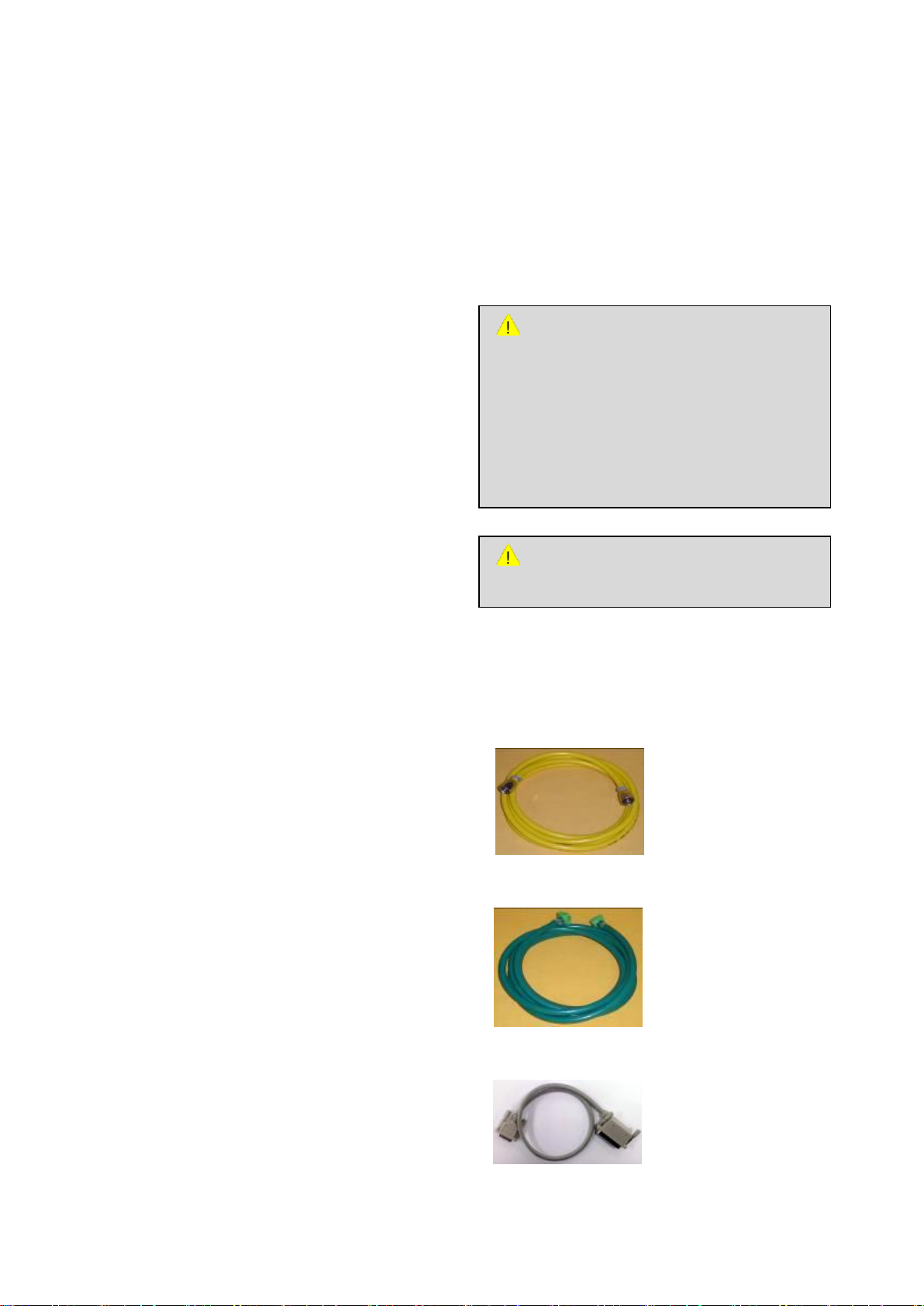
11. Technical Specification
CAUTION
Only use parts supplied by our company.
WARNING
- A/S on the device must be carried out by
an exp erienced exp ert trained by our
company.
- A/S on the device must be carried out
after separating the ventilator from the
patient.
Time Control Pressure Limited (TCPL)
- A peak inspiratory pressures is set by operator,
and during inspiration gas flow is delivered to
achieve that set pressure. Especially it is
recommended mode to neonatal patients.
11.4.2 Supported Ventilation
SPONT
- Spontaneous Ventilation
This mode provides pressure support based on
spontaneous ventilation.
tBiLEVEL
- Spontaneous Ventilation
Identical to SPONT mode, but only upper PEEP
exists.
Standard I/O Communication Port
Monitor
12.1” TFT LCD
Resolution: 800 X 600
11.6 Service
11.4.3 Combined Ventilation
VSIMV
(Volume Based Synchronized Intermittent
Mandatory Ventilation)
This mode controls ventilation based on air
volume according to spontaneous ventilation of
the patient.
PSIMV
(Pressure Based Synchronized Intermittent
Mandatory Ventilation)
This mode controls ventilation based on pressure
according to spontaneous ventilation by the
patient.
11.5 Communication / Interface
Serial Port
RS-232C – isolated
11.7 Accessories
11.7.1 Standard Accessories
- High Pressure Hose
Air Gas / Yellow (P/N : 141400020)
O2 Gas / Green (P/N : 141400030)
-Display Panel Cable (P/N :142401900)
For Upgrade Firmware Main Board, Pneumatic
Board
Baud rate: 115,200bps
MV2000[SU:M] Ventilator MEKICS Co., Ltd
65
Page 75
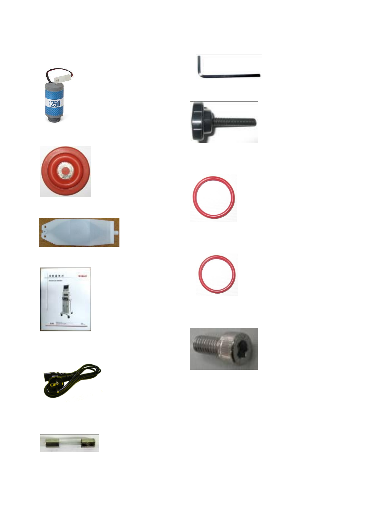
11. Technical Specification
-O2 Cell (P/N:140500660) : Installed inside
- PEEP Silicone Plate (P/N : 140601420)
- Test Lung (P/N :140602600)
-Wrench Driver (P/N : 140800720)
-Circuit Arm Fix Knob (P/N :140403490)
-53010(O-Ring) (P/N : 142100400)
O-Ring for PEEP Module
- Operation Manual (P/N : 141700610)
-Power Cord (P/N : 140600530)
3m, 220VAC
-53030(O-Ring) (P/N: 142100410)
O-Ring for PEEP Module
-Monitor Fix Bolt (P/N: 140800330)
M5x12mm Wrench Bolt(For Monitor)
-Body Cover (P/N: 150000160)
-Fuse (P/N : 141300170)
Inlet 50T 6.3A 250V 20mm
MV2000[SU:M] Ventilator MEKICS Co., Ltd
66
Page 76

11. Technical Specification
MV2000[SU:M] Ventilator MEKICS Co., Ltd
67
Page 77

11.8 Setting Parameter
Setting range
Default
Predicted Body Weight
~ 150 kg
-
Tidal Volume
5 ml ~ 2500 ml
Inspiratory Pressure
5 ~ 80 cmH2O
-
Pressure Support
0 ~ 60 cmH2O
5 cmH2O
Respiratory Rate
2 ~ 150 bpm
-
Inspiratory time
0.2 ~ 9.9 sec
-
Plateau Time
(Pause Time)
0 ~ 2 sec
0.1 sec
PEEP
0 ~ 45 cmH2O
3 cmH2O
High PEEP(t-Bilevel)
3 ~ 45 cmH2O
10 cmH2O
Low PEEP(t-Bilevel)
0 ~ 42 cmH2O
3 cmH2O
Inspiratory Pressure limit(PRVC/O2
Stream®)
10 ~ 80 cmH2O
Minute Volume(AutoVent®)
70 ~ 300 %
-
Inspiratory Flow rate(O2 Stream®)
5 ~ 40 lpm
-
Enable inhalation trigger(En-sense)
10 ~ 80 %
30 %
Exhalation trigger Sensitivity(Ex-trig)
10 ~ 80 %
30 %
F-end
25 ~ 100 %
70 %
Inspiratory Rising Time
0.1 ~ 0.5 sec
0.2 sec
Inspiratory Rising Time PSV
0.1 ~ 0.5 sec
0.2 sec
Trigger sensitivity Pressure
OFF,
0.5 ~ 20 cmH2O
3 cmH2O
Trigger sensitivity Flow
OFF,
0.5 ~ 20 L/min
3 lpm
O2 %
21 ~ 100 %
30 %
Sigh, Tidal volume
Off, 30/60/90/120
BTPS
OFF, Auto Dry, Auto Humid
MASK
ON, OFF
Proximal Sensor
ON, OFF
Power(Single/Dual High Frequency
Ventilation)
1 ~ 100 %
MAP(Single/Dual High Frequency
Ventilation)
5 ~ 60 cmH2O
20 cmH2O
Frequency(Single/Dual High Frequency
Ventilation)
2 ~ 20 Hz
20 Hz
IMV Ex duration(Dual High Frequency
Ventilation)
0.3 ~ 6.0 sec
2.0 sec
ExRate(Dual High Frequency Ventilation)
2 ~ 120 bpm
12 bpm
Setting range
Default
11. Technical Specification
MV2000[SU:M] Ventilator MEKICS Co., Ltd
68
Page 78

Nebulizer
10 ~ 180min
Off
Inspiration pause
-
Measures lung compliance,
resistance, elasticity, Time constant
Expiration pause
-
Measures auto-PEEP
Manual Inspiration
-
Delivers one mandatory breath
100% O2
-
Delivers 100% oxygen for 3 minutes
Key lock
-
Key&Touch Lock
Graph freeze
-
Freezes waveform & loop graphs
Alarm silence
-
Turns off alarm sound for 2 minutes
Alarm reset
-
Clear active alarms
※ Measurement Condition
1. Pressure
A. ± (1.7 + 4% of the actual reading) cmH
2. Volume
A. ± 15 % (Tidal Volume >100ml)
B. ±20ml (Tidal Volume ≤100ml)
3. Rate
A. ±2 bpm
4. O
2
A. 3%
5. Inspiratory Time
A. ±10%
11. Technical Specification
O
2
MV2000[SU:M] Ventilator MEKICS Co., Ltd
69
Page 79
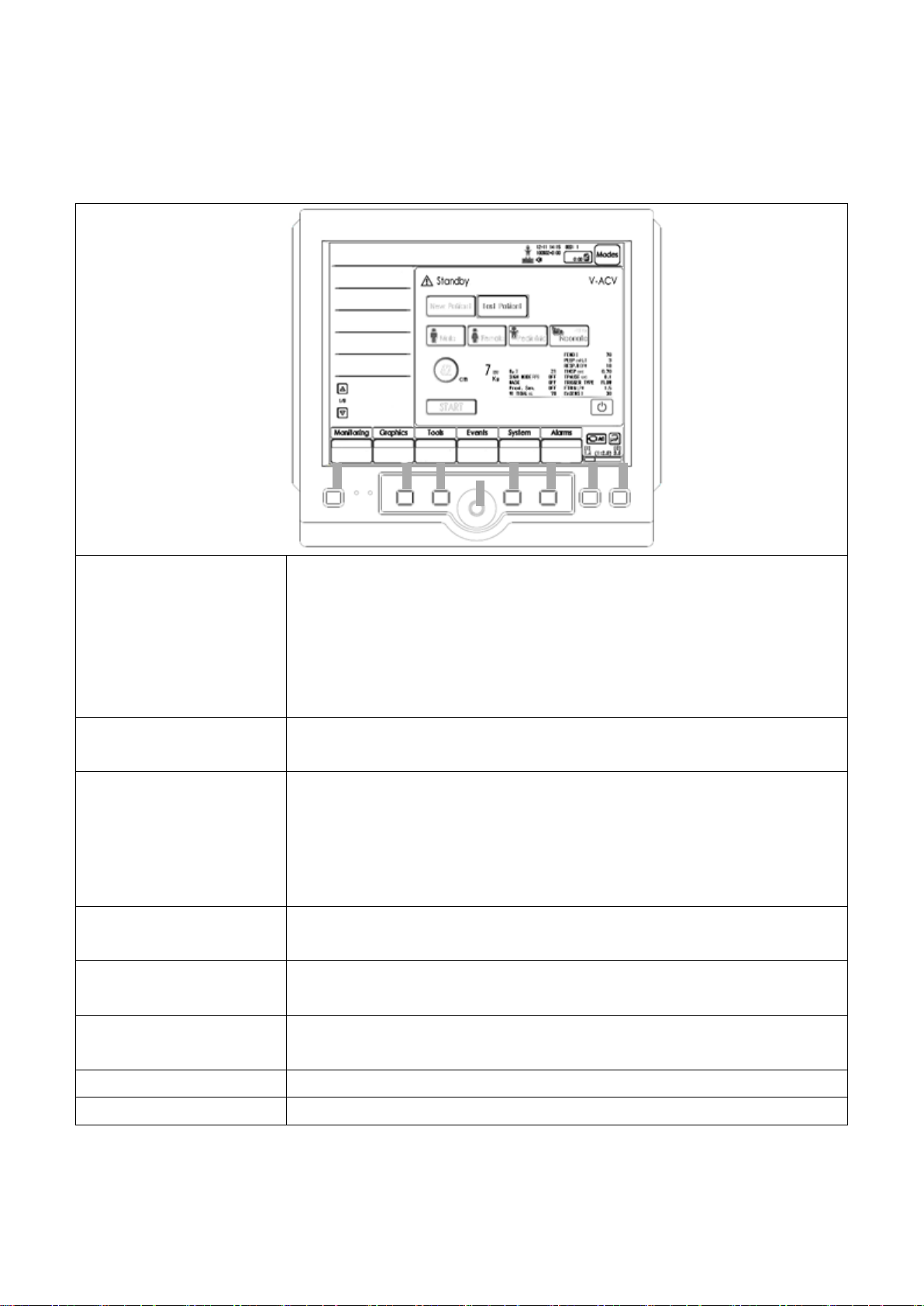
12. Summary of Screen Usage
1) On/Off Switch, Standby
To turn power ON, push this button for 0.5 second. To turn power OFF,
push this button during VENT mode operation for 10 seconds.
If the device is not in operation, power is turned OFF by pushing for 5
seconds.
The device enters stand-by mode by pushing the button during VENT
mode operation.
2) Manual Inspiration
Inspiration is manually carried out once using current setting values by
pushing this button.
3) O2 100%
100% oxygen is supplied for three minutes by pushing 100% O2 key.
Concentration is automatically returned to original oxygen concentration
after three minutes.
If O2 100% button is pushed again during three minutes of 100% oxygen
supply, 100% O2 supply is terminated and original concentration is returned.
4) Encoder
Rotate the encoder to select wanted menu or wanted setting value.
Sub menu is selected or setting value is saved by pushing the encoder.
5) Exit
This button is used with encoder and touch key to operate menu or to clear
the touch window.
6) Run
This button is used for final operation of the ventilator using values in
ventilator set.
7) Alarm Silence (2min)
Auditory signal of alarm is muted for two minutes.
8) Alarm Reset
This is operated upon reset of alarm. Alarm light is turned off.
1 2 3 4 5 6 7
8
12.1 Fixed Keys
12. Summary of Screen Usage
MV2000[SU:M] Ventilator MEKICS Co., Ltd
70
Page 80
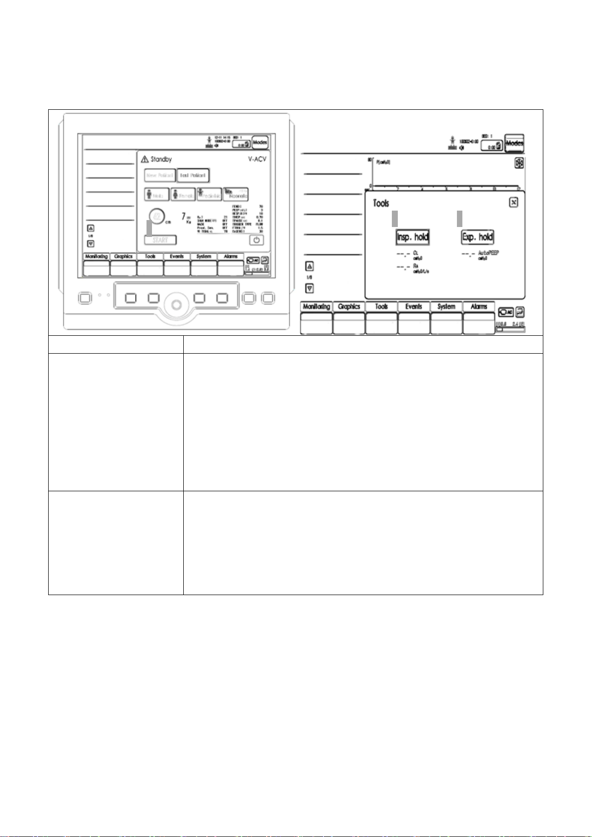
12.2 Special Function Keys
1) START
START button executes ventilation on the patient using current setting.
2) Insp.Hold
(Inspiratory Hold)
This can be executed in Tools menu among menu at the bottom.
Temporary hold function is operated after inspiration whenever button is
pushed by user.
Compliance and resistance are measured after maintaining hold for one
second. Inspiration end pressure of lung can be accurately measured using
this function.
It can be used during x-ray or to determine static compliance, static
resistance, elastance and time constant calculation.
3) Exp.Hold
(Expiratory Hold)
This can be executed in Tools menu among menu at the bottom.
Temporary hold function is operated after expiration whenever button is
pushed by user.
Auto PEEP is measured after maintaining hold for one second.
Expiration end pressure of lung can be accurately measured using this
function.
1 2 3
12. Summary of Screen Usage
MV2000[SU:M] Ventilator MEKICS Co., Ltd
71
Page 81
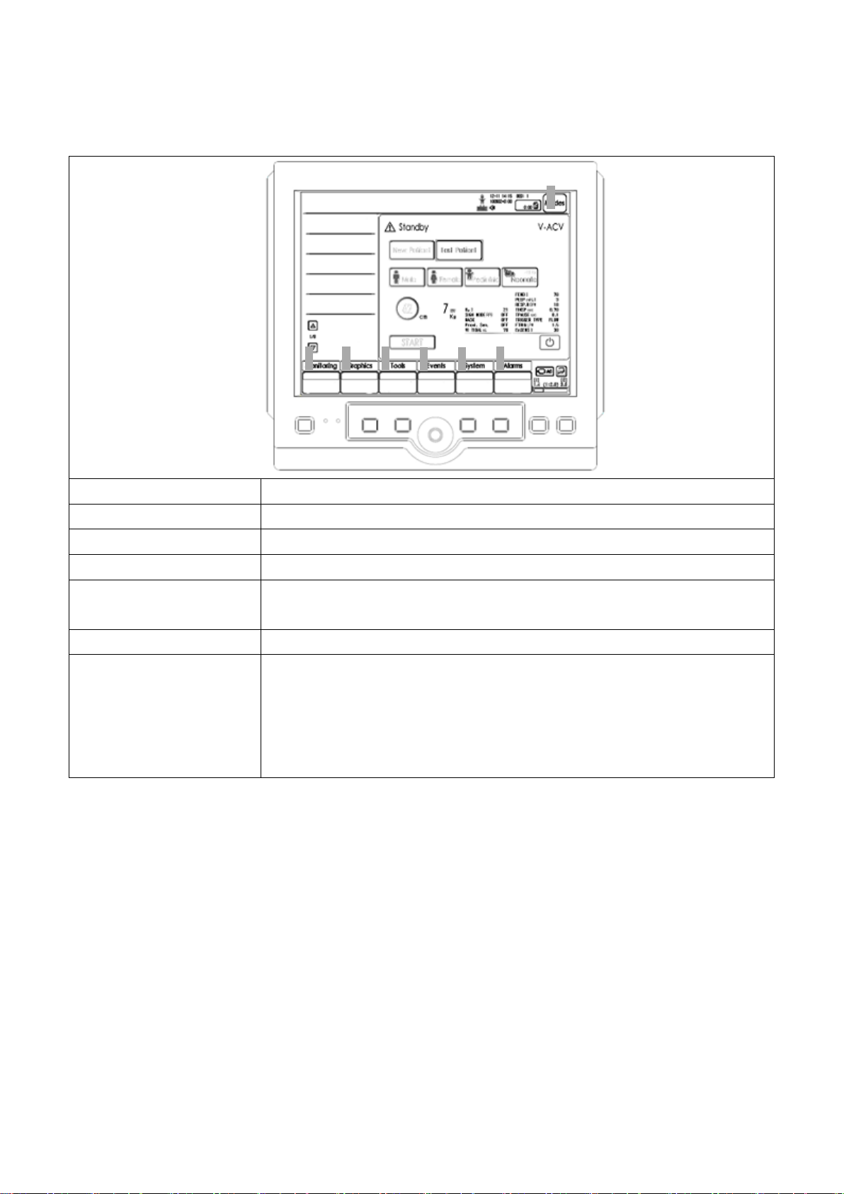
12.3 Menu Keys
1) Monitoring
Comprehensively shows data measured in each mode.
2) Graphics
Configures screen layout and trend timing.
3) Tools
Uses inspiration hold and expiration hold functions.
4) Events
Events that occur during operation of the ventilator can be checked.
5) System
Composed of operation condition setting, patient information, date, and
various calibration settings.
6) Alarms
This menu is used to configure various alarms on measurement values.
7) Modes
If Modes is pushed to select ventilation mode, setting window for
corresponding ventilation mode appears. Accept / Cancel can be used to
save or cancel the selected ventilation mode. If Accept button is pushed,
new ventilation starts as configured by user. If Cancel button is pushed,
existing ventilation is maintained.
1 2 3
4
5 6 7
12. Summary of Screen Usage
MV2000[SU:M] Ventilator MEKICS Co., Ltd
72
Page 82
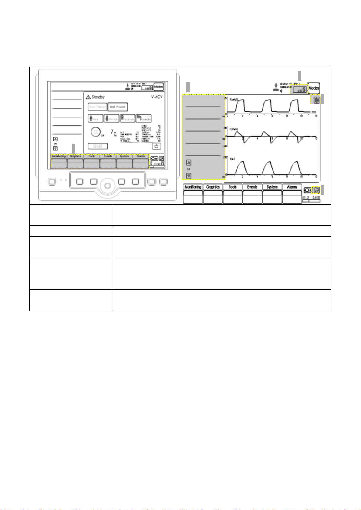
12.4 Screen Touch Pads
1) Direct Access
When changing setting values during ventilation, setting values for each
ventilation mode can be changed.
2) Nebulizer
Nebulizer is turned On/Off using touch pad.
3) Freeze
If Freeze pad is pushed, graph freezes temporarily. Trend value can be
searched in trend screen.
4) Measurement Value
Measurement values during ventilation are displayed. More measurement
values can be seen by touching arrows. Use [Monitoring] menu to see
values at once.
5) Touch Screen key Lock
Push Key Lock pad to disable all touches on the screen.
Touches are enabled by pushing Key Lock once again.
1
3
5
4
2
12. Summary of Screen Usage
MV2000[SU:M] Ventilator MEKICS Co., Ltd
73
Page 83

13. MV2000[SU:M] Series Features
SU:M1
SU:M2
SU:M3
Mode
V-ACV
○ ○ ○
P-ACV
○ ○ ○
SIMV
○ ○ ○
SPONT
○ ○ ○
Apnea Backup
○ ○ ○
Mask Ventilation
(Non-Invasive)
○ ○ ○
TCPL
○ ○
PRVC
○ ○
tBiLevel
○ ○
AutoVent
○ ○
HFV(SHFV/DHFV)
○
Optional
O2 Stream
(with Nasal Cannula)
○ ○ ○
Hemo Dynamics
(with SpO2 and EtCO2)
○ ○ ○
Proximal Sensor
(Adult & Neonate)
○ ○ ○
13. MV2000[SU:M] Series Features
MV2000[SU:M] Ventilator MEKICS Co., Ltd
74
Page 84

Annex 1. Introduction
CAUTION
- All users must always be aware of risks
of contaminated parts when separating
and cleaning the ventilator.
- All disposable parts must be handled
according to disposal method of each
hospital or disposed using eco friendly
methods.
NOTE
The mark above is “NOTE.”
The mark describes relevant items and
additional information. Contents included in
the note mark do not damage patients and
devices.
ATTENTION
The mark above is “ATTENTION.”
The mark indicates information and tips on
for use and easy connection of components.
CAUTION
The mark above is “CAUTION.”
The mark warns users on precautions that
may cause damage to devices and patients.
WARNING
The mark above is “WARNING.”
The mark warns users on precautions that
may cause great or irrecoverable damage to
devices and patients.
Appendix 1. Introduction
Unless specifically mentioned, operation and
information on MV2000[SU:M] ventilator shall be
based on details of this User Manual.
This Annex describes sterilization and maintenance
of the ventilator.
Warning, Caution, and Important
Matters
Overall Outline
Since there are diverse sterilization methods by
different medical institutions, our company cannot
provide a specific sterilization method that
satisfies all medical institutions. In addition, our
company is not responsible for the effects of
sterilization process performed while configuring
patient treatment.
Our company recommends using devices and
methods described in this Annex. Unless certified
by our company, we do not guarantee
compensation for damages in the device or parts
using methods not recommended here.
MV2000[SU:M] Ventilator MEKICS Co., Ltd
75
Page 85

Annex 1. Introduction
ATTENTION
- When handling ventilator parts, follow
infectious substance management
guideline by each hospital.
- If possible, immediately clean the device
after use. Always clean before
sterilization or disinfection. When drying,
make sure there are no blood and
impurities on parts and device.
- Water quality may influence cleaning and
sterilization. Our company recommends
use of drinking water quality as minimal
water quality.
- Our company recommends use of
bacteria filters or equivalent devices in
order to reduce spread of bacteria from
patients to exp iratory cassette. Use of
such filters and devices can reduce risk
of infection. Lifespan of the product can
be extended by reducing cleaning
process of expiratory cassette.
MV2000[SU:M] Ventilator MEKICS Co., Ltd
76
Page 86
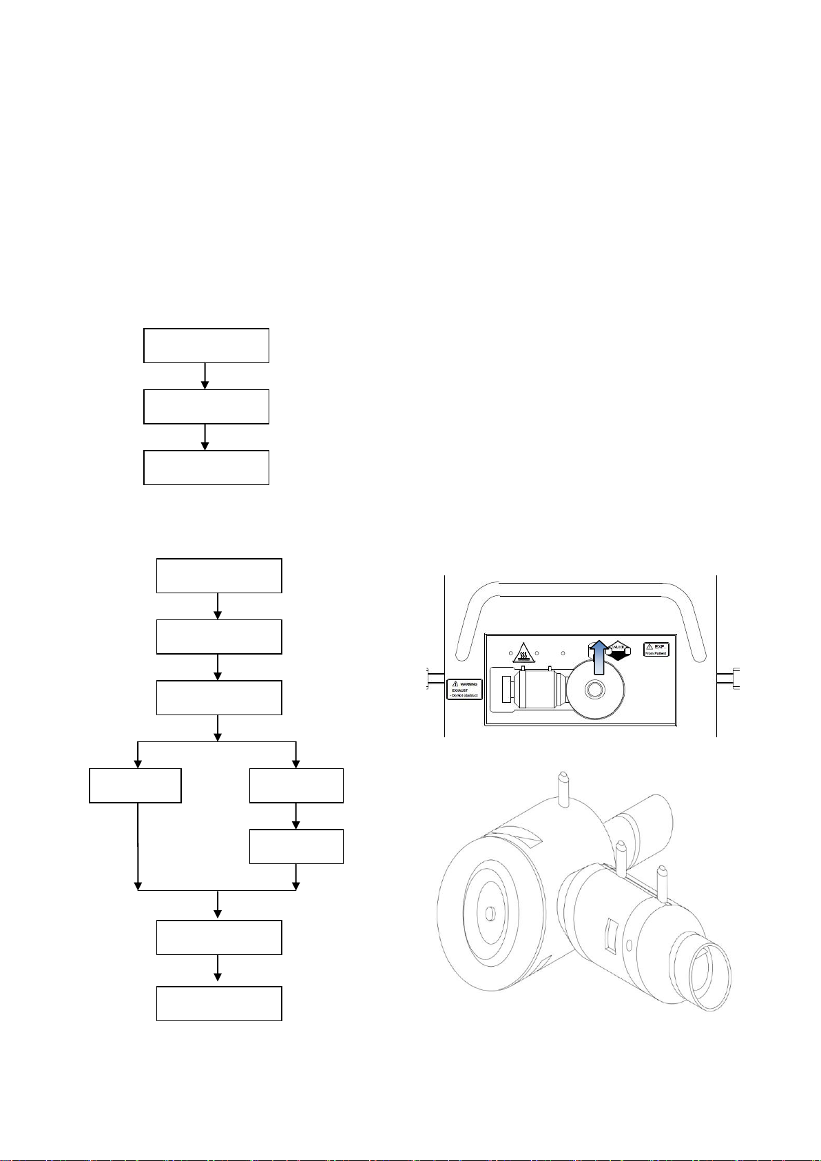
Annex 2. Cleaning / Sterilization
Disassembly
Wiping / Disposal
Cleaning
Cleaning
Sterilizer
Disinfectant
Cleaning
Drying
Assembly
Disassembly
Wiping / Disposal
Assembly
Appendix 2. Cleaning / Sterilization
Appendix 2.1. Summary of Cleaning /
Sterilization Process
This Appendix provides summary of cleaning,
sterilization, and disinfection processes.
Cleaning process using bacteria filter
Cleaning process without using bacteria filter
Appendix 2.2. Preparation /
Disassembly
Appendix 2.2.1 Preparation
- Turn off the power of ventilator using switch
button on the back of main body.
- Separate main power and gas hoses from the
ventilator.
- Turn off the power of surrounding devices and
separate them from the ventilator.
Appendix 2.2.2 Expiratory Cassette
Separation
- Separate all silicon hoses connected to
expiratory cassette.
- After raising the lock handle, pull the cassette
bundle forward for separation.
MV2000[SU:M] Ventilator MEKICS Co., Ltd
77
Page 87
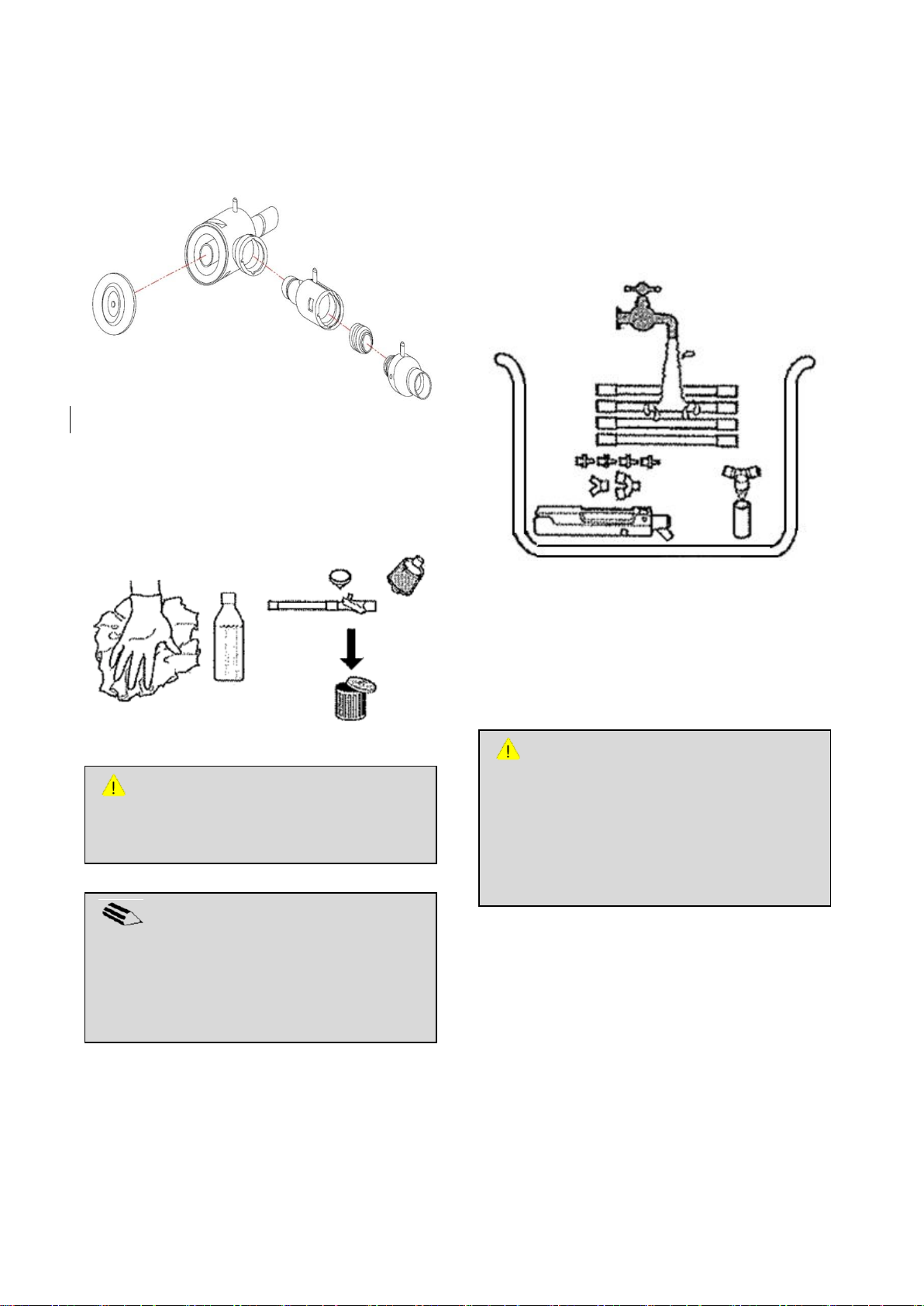
Annex 2. Cleaning / Sterilization
ATTENTION
Cleaning of cassette immediately after use is
another effective method of sterilization.
Cleaning can easily remove contaminants
and reduce risks of cross infection between
patients.
NOTE
In case of severe degree of contamination,
ethyl alcohol (70%) or isopropyl alcohol (70%)
is used. Avoid contact with electronic
connectors.
CAUTION
Do not place battery, EtCO2 module and SpO2
sensor in any solution.
- Cassette is separated by rotating the junction
marked in the drawing below.
- Disassemble the cassette as in the drawing.
Appendix 2.3. Wiping / Disposal
Appendix 2.3.1. Wiping
Wipe ventilator and all parts using soft cloth with
detergent or disinfectant.
Appendix 2.3.2 Disposal
- Bacteria filters
- Humidifier / HME (disposable humidifier)
- Disposable tube
Appendix 2.3.3. Cleaning Before Sterilization
If cleaning process is not included prior to
MV2000[SU:M] Ventilator MEKICS Co., Ltd
sterilization using cleaning sterilizer, take the
following steps.
- Place parts in water (<35℃/95℉) and clean.
- Make water pass through the parts.
78
Page 88
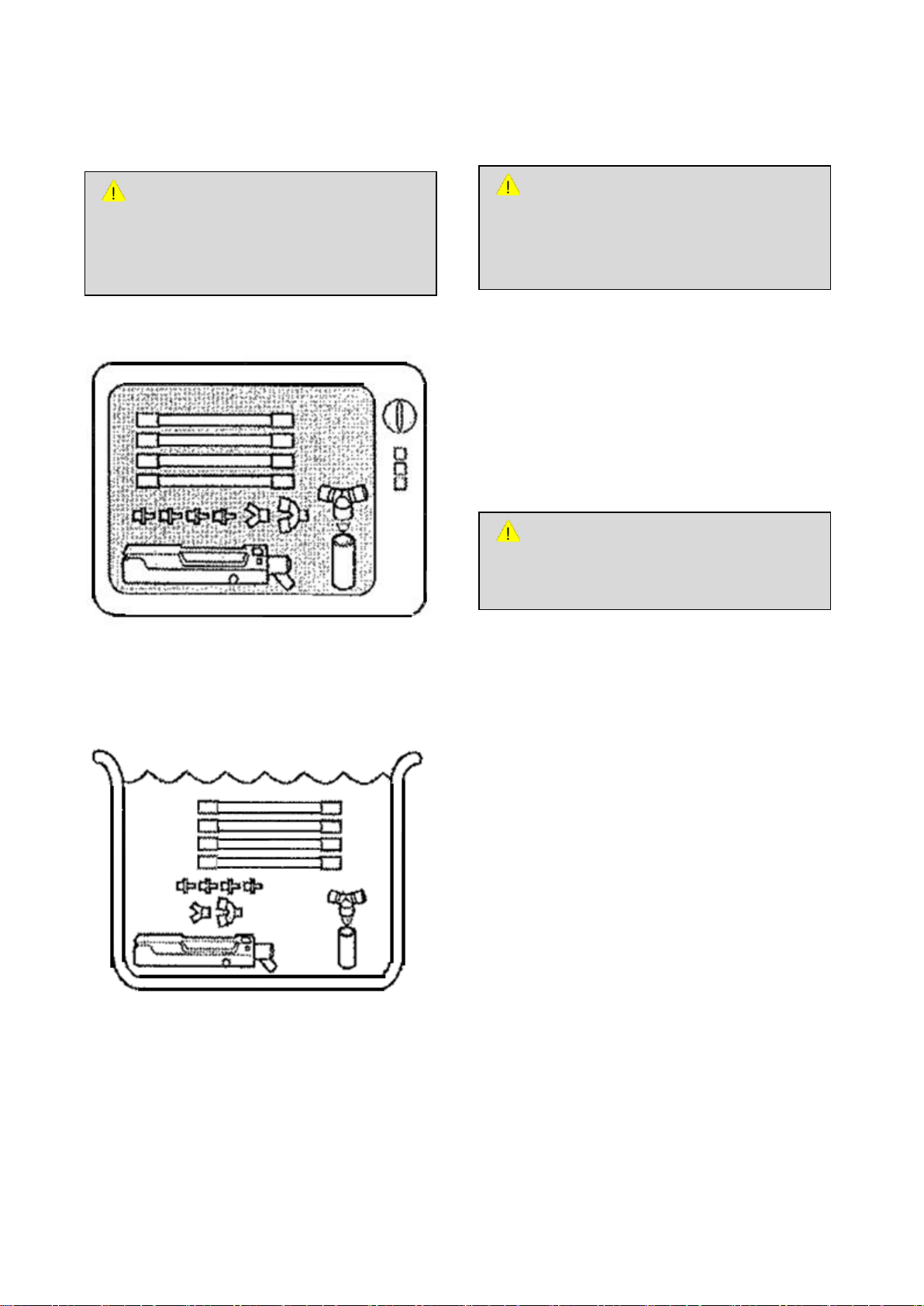
Annex 2. Cleaning / Sterilization
ATTENTION
Chemical precipitates may influence the
patient, induce leakage, or damage parts.
ATTENTION
Follow recommendations and guidelines by
the manufacturer. Failure to do so may
cause damage on the product.
ATTENTION
- Since exp iratory cassette is a precise
part, it must be handled carefully.
- All parts must be dried after sterilization.
Appendix 2.4 Sterilization Process
Appendix 2.4.1 Cleaning Sterilizer
- Anioxide 1000
Appendix 2.4.3 Rinsing After Sterilization
- Rinse sufficiently with water to remove all
disinfectants from parts. Clean parts in running
water.
- Turn upright, shake horizontally, and tilt.
- Repeat the above step at least 5 ~ 7 times.
- Clean all parts in a cleaning sterilizer at
temperature of 85-95℃ (185-203℉).
Appendix 2.4.2 Disinfectant
Place parts in one of the following disinfectants.
- Alcohol (ethyl or isopropyl alcohol 70%)
Appendix 2.4.4 Drying Method
Expiratory cassette must be dried before use.
Dry the cassette using the following method.
- Repeat shaking and tilting of expiratory
cassette 5 ~ 7 times.
- Dry expiratory cassette in a dryer of up to 70℃
(158℉) for one hour.
- If there is no dryer, air dry expiratory cassette
for 12 ~ 24 hours.
- CidexOPA
- Hexanios G+R
- Aniosyme DD1
- Gigazyme Plus
MV2000[SU:M] Ventilator MEKICS Co., Ltd
79
Page 89
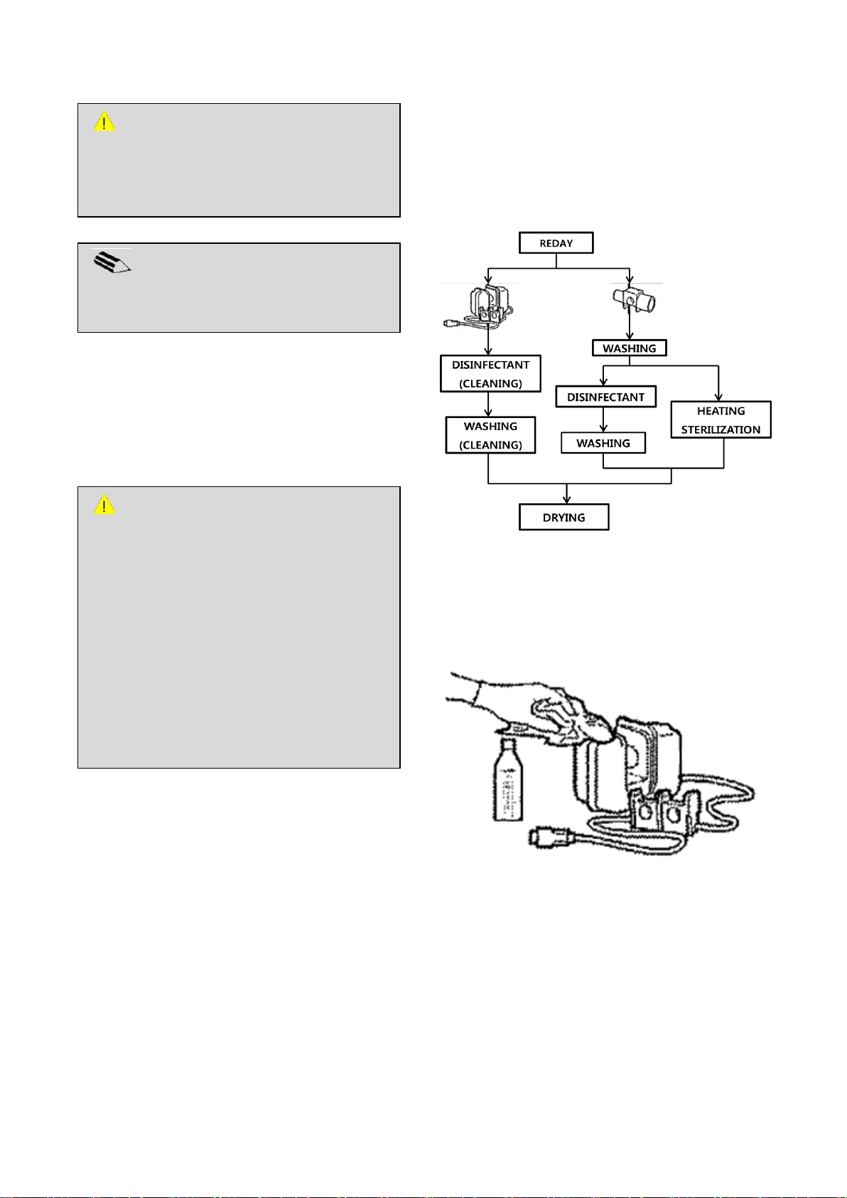
WARNING
- Make sure that exp iratory cassette
makes “clicking” sound during assembly.
- After cleaning and sterilization, record it
in a log according to the hospital’s
regulation.
- Once assembly is complete, perform
pre-use check using test lung.
- If the product does not operate properly,
re-check assembly of expiratory cassette
and verify connection of tubes.
NOTE
If drying process is carried out by cleaning
sterilizer, no separate drying is required.
CAUTION
Since inside of expiratory cassette can be
damaged, do not dry expiratory cassette
using high pressure gas.
Appendix 2.5 Assembly
- Assemble expiratory cassette in the reserve
sequence as disassembly.
Annex 2. Cleaning / Sterilization
Sterilization
Clean and sterilize after using on a patient or
dispose according to the hospital’s policy.
Appendix 2.6 EtCO2 Module Cleaning /
MV2000[SU:M] Ventilator MEKICS Co., Ltd
Appendix 2.6.1 Preparation
- Separate EtCO2 from the ventilator.
Appendix 2.6.2 EtCO2 Module Body
- Wipe the main body using soft cloth with
disinfectant (Cidex OPA or isopropyl alcohol
70%).
80
Page 90
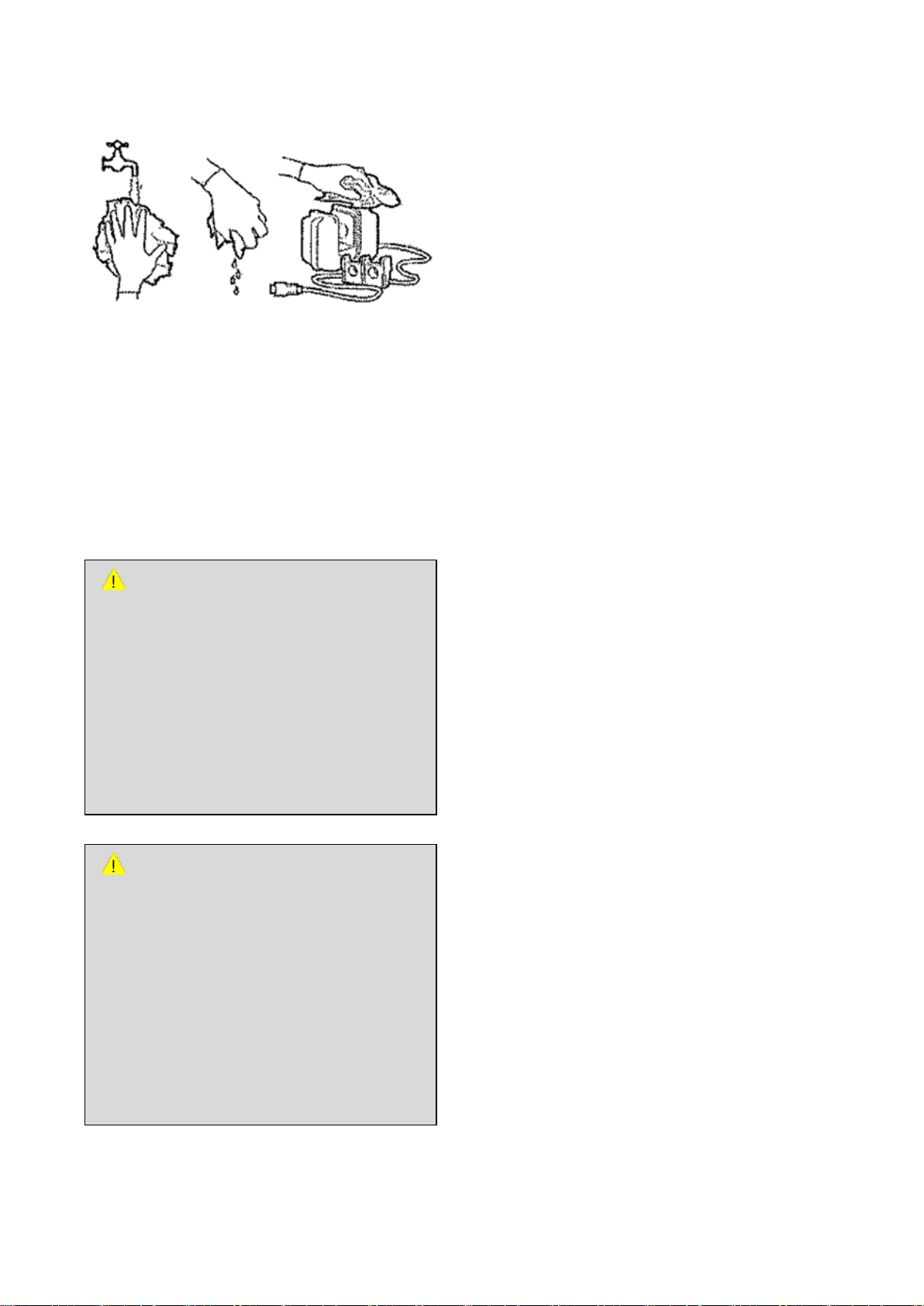
Annex 2. Cleaning / Sterilization
ATTENTION
Follow recommendations and guidelines of
the manufacturer on the use of
disinfectants.
- Airway adapter for adults can be sterilized
for 4 ~ 7 minutes at 134℃ (273℉) in
accordance to sterilization regulation of
each hospital.
- After sterilization process, adapter must be
dried prior to use.
ATTENTION
Do not place EtCO2 module in solutions like
water.
- Place airway adapter in Cidex OPA
solution during sterilization.
- Clean airway adapter using distilled
water.
- Airway adapter must be dried and wiped
before re-using.
- After cleaning and sterilization, wipe the module
using soft cloth soaked in water.
- Module must be dried after cleaning and
sterilization.
Appendix 2.6.3 Airway Adapter
Airway adapter can be disinfected or sterilized.
Appendix 2.7. Accessories
MEKICS Humidifier VH-2600
Refer to User Manual of MEKICS Humidifier for
details on cleaning and sterilization methods.
MV2000[SU:M] Ventilator MEKICS Co., Ltd
81
Page 91
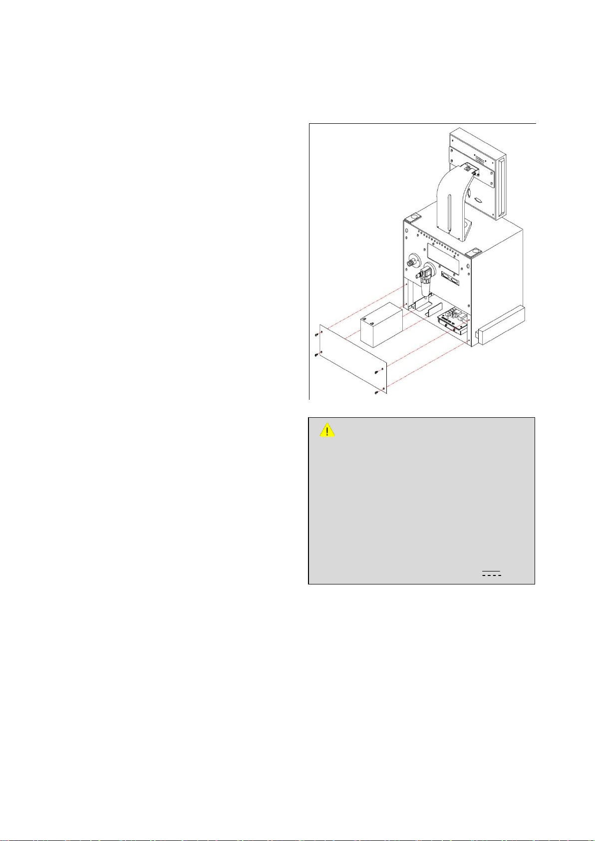
Annex 3. Maintenance
WARNING
Be careful about polarity when replacing
battery. Connect (+) to red and (-) to black (if
polarity is mistaken, it may damage the
product).
Since current is high, battery may explode
from short circuit and cause harm on human
body.
Use rated voltage and current (12V , 7A).
Appendix 3. Maintenance
Appendix 3.1. Preventive Maintenance
The device must be regularly inspected. Preventive
maintenance included in service manual is carried
out in case the amount of use of the ventilator is
smaller than ordinary use. Receive at least one
inspection per year from the technical team of our
company. In general, a ventilator is expected to
run about 5,000 hours per year.
Always clean inspiratory channel prior to
preventive maintenance. Inspiratory cleaning must
be performed by a trained expert.
Appendix 3.2. Battery Replacement
Refer to the following diagram for battery
replacement.
Internal battery is used to supply power to the
product when the patient is moving. Battery is
automatically charged when external commercial
power is supplied. Once commercial power supply
is terminated or power supply is suspended
accidentally, power is automatically switched to
internal battery. Remaining battery is indicated on
the LCD monitor.
If there is a problem in commercial power or
patient must be transported while the product is
in operation, battery must be charged. Replace the
battery if it is considered inadequate.
If voltage is inappropriate, measurement value
may result in errors. If battery is low, connect to
commercial power.
In case of abnormality in battery, contact [Sales /
Customer Service] to receive necessary service.
MV2000[SU:M] Ventilator MEKICS Co., Ltd
Appendix 3.3. Accessories
82
Page 92

Annex 3. Maintenance
CAUTION
If defect is caused by inappropriate handling
or careless management of the product, the
manufacturer and its sales agencies are not
responsible for any damages.
Fischer & Paykel Humidifier MR850
Refer to User Manual of Fischer & Paykel
Humidifier for details on cleaning and sterilization
methods.
Appendix 3.4. Warranty Period
- This product was manufactured based on
strict quality management and testing process
of our company.
- Compensation criteria for product repair and
replacement are as announced in “Consumer
Injury Compensation Rule” by the Economic
Planning Board.
- Warranty period for this product is regulated
as one year since installation. However,
warranty period for LCD, battery and O2
sensor is six months.
- If the product shows defects under normal
use during warranty period, our customer
service team will repair defects free of charge
during warranty period.
- Prescribed service fees are levied after repair
in the following cases.
Defect from natural disasters such as fire,
earthquake and lightning
Defect from inappropriate movement or
carelessness in use of the product after
installation
Defect from repair or renovation made by
an individual other than service agents
number, purchase date and problem.
Please contact the following numbers and
addresses to receive various services and products
or to contact the Sales Department of our
company.
[Manufacturer / Customer Service Team]
MEK ICS Co., Ltd.
144-3 Sangdaewon-dong Jungwon-gu Seongnam,
Gyeonggi Province
5F, 5th Woorim Lions Valley, Buliding A
Sales: +82-70-7119-2520
Customer Service: +82-70-7119-2552
FAX: +82-31-735-2761
Web site: http://www.mek-ics.com
E-mail:[email protected]
We are also receiving customer complaints
through MEK ICS web site. If you experience any
discomforts or improvements to be made on the
product, please feel free to contact our company
or its customer service team at any time.
designated by MEKICS
- Preparations for repair requests
If defect occurs, immediately stop the use
and check details on the defect in this
manual.
Before contacting our company’s
customer service team for repair request,
please check model name, manufacture
MV2000[SU:M] Ventilator MEKICS Co., Ltd
83
 Loading...