

Version
Date
Change content
ReMarks
V1.0
2017/8/24
Frist edition
Confidential Document
@MEIZU
File number:MZ-CSGY-03-0340
M1721 Disassembly and assembly guide
(VERSION:V1.0)
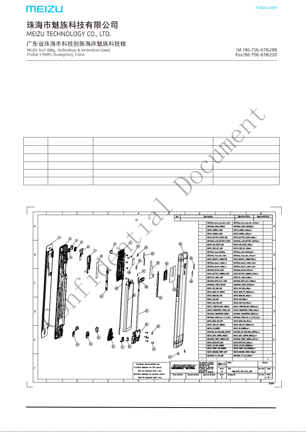
Ⅰ、Mobile phone structure introduction
Approved by:Chuansan Wang Reviewed by:Zhifeng Zhong Edited by:Jun Wang

Confidential Document
@MEIZU
Ⅱ、Disassembly Tools
1、0.8mm Torx screwdriver 2、plastic tweezers 3、Philips screwdriver
4、FPC lever 5、Pin 6.Metal tweezers(as below picture)
Ⅲ﹑Disassembly Guide
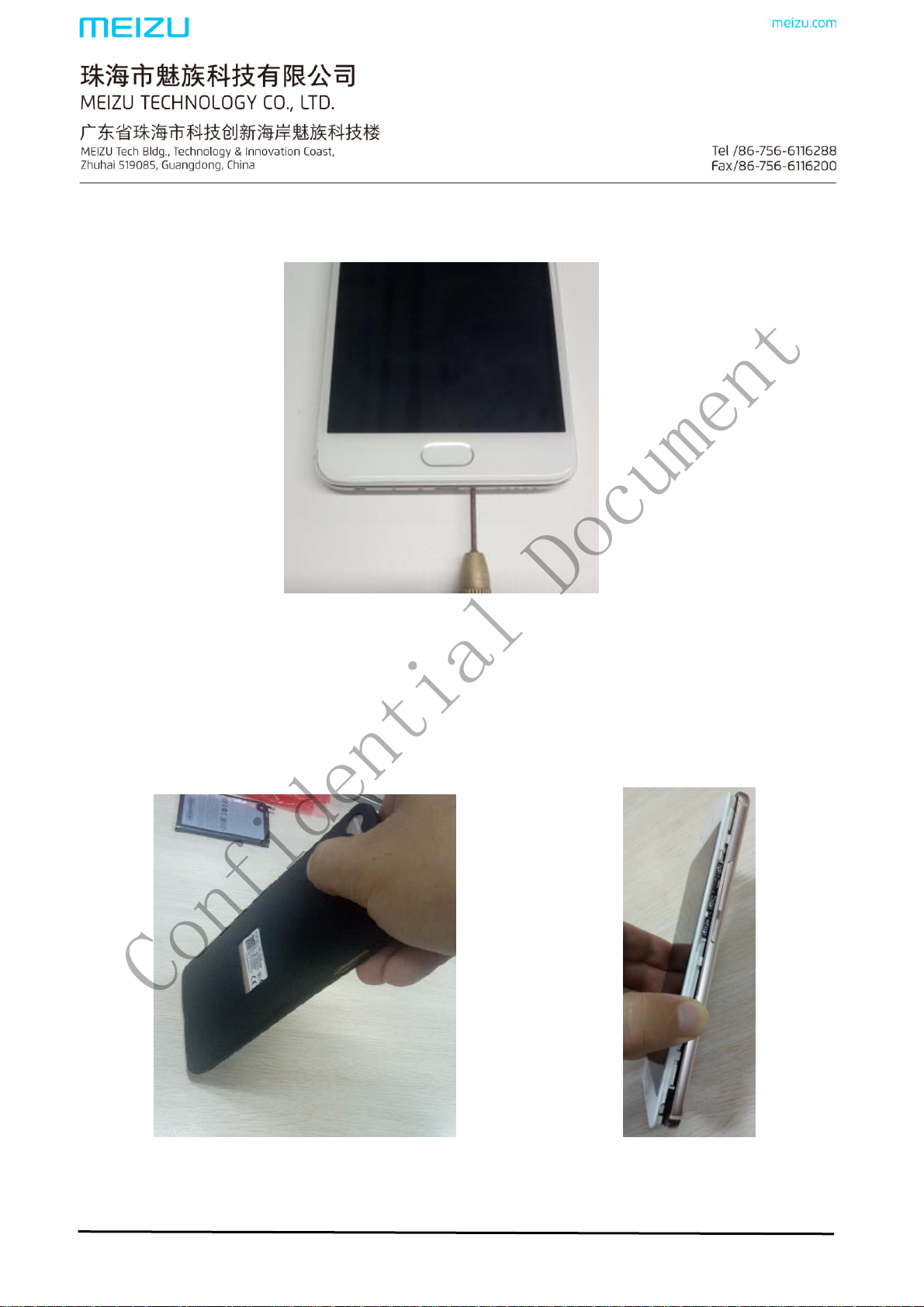
1、 Make sure the phone is switched off: Press the home button, check the cellphone is on or off. If it is on.
Please press the power button to switch off.(Note: do not disassembly the cellphone when the cellphone is
on)
2、SIM Tray Removal: Insert the Ejection Pin in the phone. Push the pin harder to eject and
remove the SIM tray(as below picture)
Approved by:Chuansan Wang Reviewed by:Zhifeng Zhong Edited by:Jun Wang
Confidential Document
@MEIZU
3、TP Screw Removal *2: Use the 0.8mm Torx screwdriver to unfasten 2pcs TP screws from
the bottom of phone as below figure(as below picture)
4、Battery cover removal : 1. Place one layer of cushion on table; 2. When knocking battery
cover, keep phone to 70-80 degrees with table. Then knock one corner of phone. Knock one
corner of battery cover to separate it 1-2mm away from phone. 3.Use disassembly shim to
unfasten the back cover(Note: Remove the battery cover should take the protect film off,
and do not knock too hard to damage the cellphone )
Approved by:Chuansan Wang Reviewed by:Zhifeng Zhong Edited by:Jun Wang

Confidential Document
@MEIZU
5、B2B connector holder removal:Unfasten these B2B holder screws by Philips screws
driver. And take the B2B connector holder off.
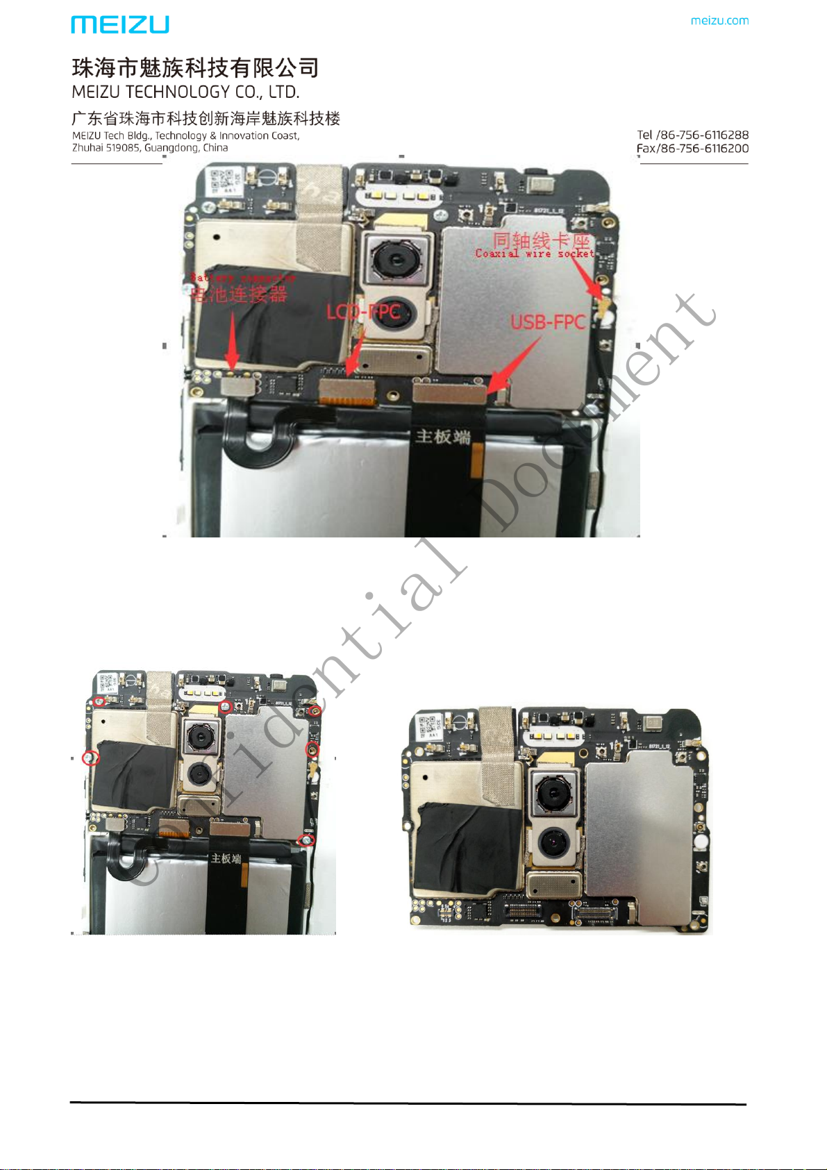
6、LCD connector 、USB-FPC、battery connector、coaxial wire removal:remove the battery
connector、USB-FPC and LCD –FPC by plastic lever. And then remove the coaxial wire
form mainboard ( Noted : Disconnect the battery connector first,. Do not touch the
components on the mainboard, avoid to damage)( as below picture)
Approved by:Chuansan Wang Reviewed by:Zhifeng Zhong Edited by:Jun Wang
Confidential Document
@MEIZU
7、Mainboard removal: Use the philips screwdrive unfasten the screws*6 ,then take the
mainboard out(as below picture)
8、Front camera back camera,and light sensor rubber case removal:Release 1、front camera
Conductive cloth 2、back camera Conductive cloth,Use the plastic lever to disconnect the
fornt camera connector and back camera connector, take the fornt camera and back
Approved by:Chuansan Wang Reviewed by:Zhifeng Zhong Edited by:Jun Wang
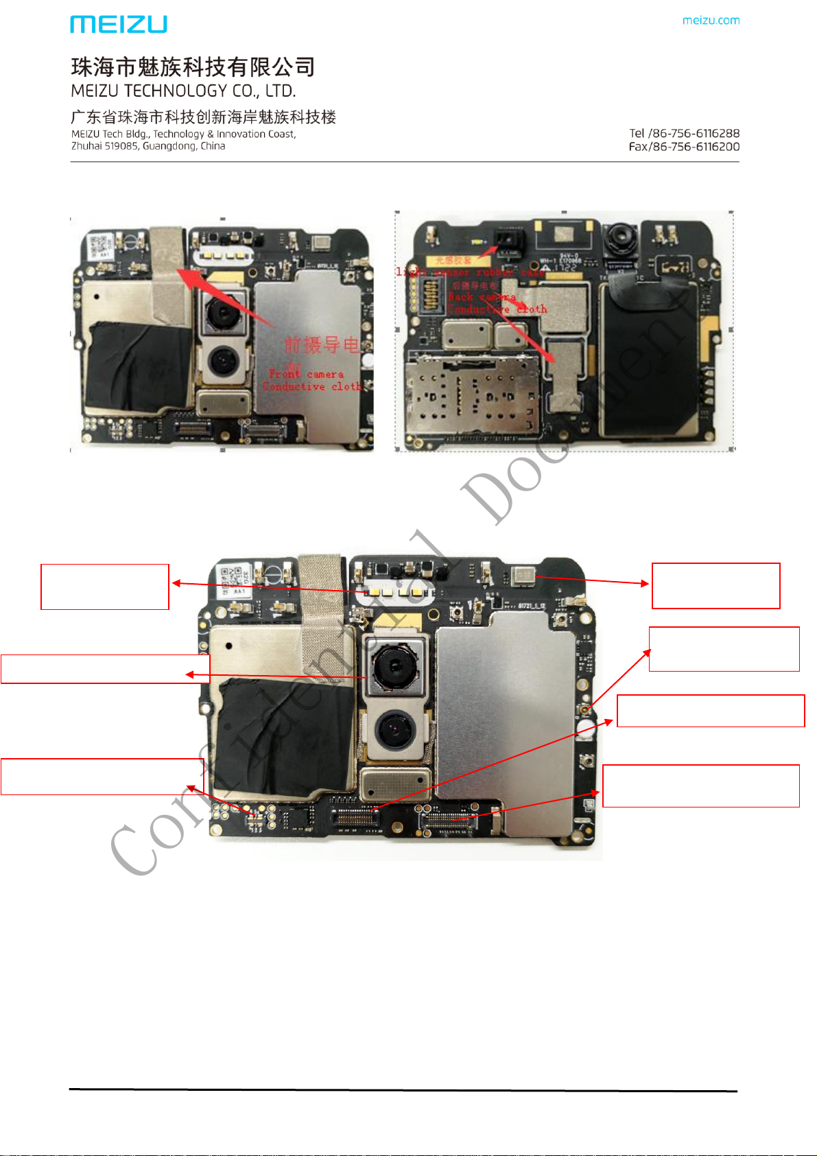
Flash light
Battery FPC connector
Vice-MIC
Coaxial wire
USB-FPC connector
LCD-FPC connector
Confidential Document
@MEIZU
camera off.and then take the light sensor rubber case off(as below picture,Do not touch the
components on the mainboard, avoid to damage)
9、Mainboard introduction
Approved by:Chuansan Wang Reviewed by:Zhifeng Zhong Edited by:Jun Wang
 Loading...