

Page 1
MEITRACK T366G User Guide
MEITRACK T366G User Guide
Page 2

MEITRACK T366G User Guide
Copyright © 2016 Meitrack Group All rights reserved. - 2 -
Change History
File Name
MEITRACK T366G User Guide
Created By
William Sun
Project
T366G
Creation Date
Update Date
2016-07-15
2016-08-09
Subproject
User Guide
Total Pages
15
Version
V1.0
Confidential
External Documentation
Page 3

MEITRACK T366G User Guide
Copyright © 2016 Meitrack Group All rights reserved. - 3 -
Contents
1 Copyright and Disclaimer ...............................................................................................................................................................- 4 -
2 Product Overview ..........................................................................................................................................................................- 4 -
2.1 Product Features.................................................................................................................................................................- 4 -
2.1.1 Sudden Acceleration/Deceleration Alarm ...............................................................................................................- 4 -
2.1.2 GPS Data Filtering ....................................................................................................................................................- 4 -
2.1.3 Activating Output by Event ......................................................................................................................................- 5 -
3 Product Function and Specifications .............................................................................................................................................- 5 -
3.1 Product Function ................................................................................................................................................................- 5 -
3.1.1 Position Tracking ......................................................................................................................................................- 5 -
3.1.2 Anti-Theft .................................................................................................................................................................- 5 -
3.1.3 Other Functions .......................................................................................................................................................- 5 -
3.1.4 Functions of Optional Accessories ...........................................................................................................................- 6 -
3.2 Specifications ......................................................................................................................................................................- 6 -
4 T366G and Accessories ..................................................................................................................................................................- 7 -
5 Device Panel ..................................................................................................................................................................................- 8 -
6 First Use .........................................................................................................................................................................................- 8 -
6.1 Installing the SIM Card ........................................................................................................................................................- 8 -
6.2 LED Indicator .......................................................................................................................................................................- 9 -
6.3 Device Configuration ..........................................................................................................................................................- 9 -
6.3.1 Installing the USB Driver ..........................................................................................................................................- 9 -
6.3.2 Configuring Device Parameters by Meitrack Manager ...........................................................................................- 10 -
6.4 Tracking by Mobile Phone .................................................................................................................................................- 10 -
6.5 Common SMS Commands ................................................................................................................................................- 12 -
6.5.1 Real-Time Location Query – A00 ............................................................................................................................- 12 -
6.5.2 Setting Authorized Phone Numbers – A71 ............................................................................................................- 12 -
6.5.3 Setting the Smart Sleep Mode – A73 .....................................................................................................................- 12 -
7 Logging In to MS03 Tracking System ............................................................................................................................................- 13 -
8 Installing the T366G .....................................................................................................................................................................- 13 -
8.1 Installing an I/O Cable .......................................................................................................................................................- 13 -
8.1.1 Interface Definition ................................................................................................................................................- 13 -
8.1.2 Wiring Diagram ......................................................................................................................................................- 15 -
8.2 Mounting the T366G.........................................................................................................................................................- 15 -
Page 4
MEITRACK T366G User Guide
Copyright © 2016 Meitrack Group All rights reserved. - 4 -
1 Copyright and Disclaimer
Copyright © 2016 MEITRACK. All rights reserved.
and are trademarks that belong to Meitrack Group.
The user manual may be changed without notice.
Without prior written consent of Meitrack Group, this user manual, or any part thereof, may not be reproduced for any
purpose whatsoever, or transmitted in any form, either electronically or mechanically, including photocopying and recording.
Meitrack Group shall not be liable for direct, indirect, special, incidental, or consequential damages (including but not limited to
economic losses, personal injuries, and loss of assets and property) caused by the use, inability, or illegality to use the product
or documentation.
2 Product Overview
The T366G is a vehicle GPS tracker with IP67 water-resistance rating and can be installed into cars, motorcycles, yachts, and
boats. It is equipped with built-in GPS and GSM antennas. The unit can work well in extreme environments.
2.1 Product Features
2.1.1 Sudden Acceleration/Deceleration Alarm
You can detect the sudden acceleration/deceleration alarm by setting the limit value.
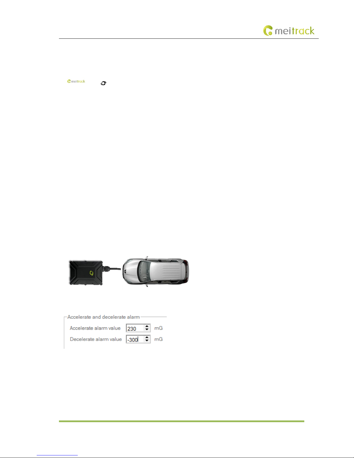
Cautions on device installation:
1. The device should be installed into the vehicle according to the following direction.
2. The device installation angle cannot exceed 15 degrees.
The default sudden acceleration and deceleration alarm values are 230 mG and -300 mG respectively.
Note: The alarm results vary according to the device installation, vehicle model, vehicle weight, and driving behaviors. After the
device has been installed properly, you can use the Meitrack Manager software to adjust the sudden acceleration and
deceleration alarm values by every 10 mG. You can also use the D79 command to set the values.
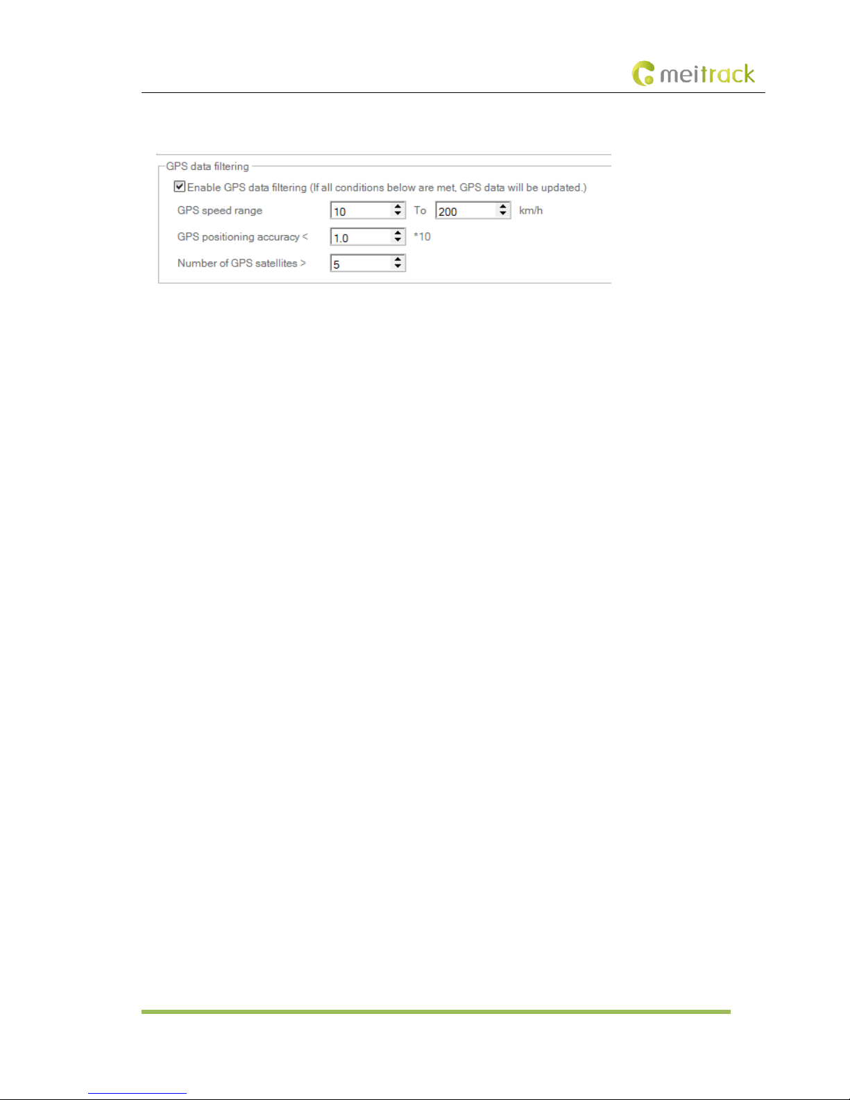
2.1.2 GPS Data Filtering
The GPS data filtering function can ensure GPS data accuracy and eliminate static drifting.
Page 5
MEITRACK T366G User Guide
Copyright © 2016 Meitrack Group All rights reserved. - 5 -
You can set the following parameters by Meitrack Manager: GPS speed range, GPS positioning accuracy, and Number of GPS
satellites. When the GPS data filtering function is enabled, if all conditions are met, GPS data will be updated.
Note: This function can be enabled by Meitrack Manager.
2.1.3 Activating Output by Event
You can activate output by event.
For example:
1. When speeding is detected, the buzzer will make sounds.
2. When unauthorized ignition or GPS antenna cut-off is detected, the engine will not be able to start.
3. When iButton triggering is detected, the vehicle door will open or close.
4. When input or output status is detected, the output will be active or inactive.
3 Product Function and Specifications
3.1 Product Function
3.1.1 Position Tracking
GPS + LBS positioning
Real-time location query
Track by time interval
Track by distance
Track by mobile phone
Speeding alarm
Heading change report
3.1.2 Anti-Theft
Polygon geo-fence alarm
Engine or vehicle door status alarm
Remote vehicle fuel/power cut-off alarm
GPS blind spot alarm
Towing alarm
3.1.3 Other Functions
SMS/GPRS (TCP/UDP) communication (Meitrack protocol)
Built-in 8 MB buffer for recording driving routes
Page 6
MEITRACK T366G User Guide
Copyright © 2016 Meitrack Group All rights reserved. - 6 -
IP67 water-resistance rating
Mileage report
Support Over-the-Air (OTA) update.
Smart sleep mode
Built-in 3D acceleration sensor
Online Parameter Editor
GPS data filtering
Activate output by event
Halt to Start and Start to Halt alarms
Vehicle power protection
3.1.4 Functions of Optional Accessories
Optional Accessories
Function
iButton
Identify the driver ID and grant permission to start the vehicle.
A53 fuel sensor
Check the fuel level and detect a fuel theft alarm.
Digital temperature sensor
Check temperature (Used with the A61 sensor box).
400 mAh/3.7 V high-temperature battery
(-20°C to 80°C)
Extend device's usage time after the external power supply is cut off.
When the battery power is low, a low battery alarm will be generated.
400 mAh/3.7 V normal-temperature
battery (-20°C to 60°C)
Extend device's usage time after the external power supply is cut off.
When the battery power is low, a low battery alarm will be generated.
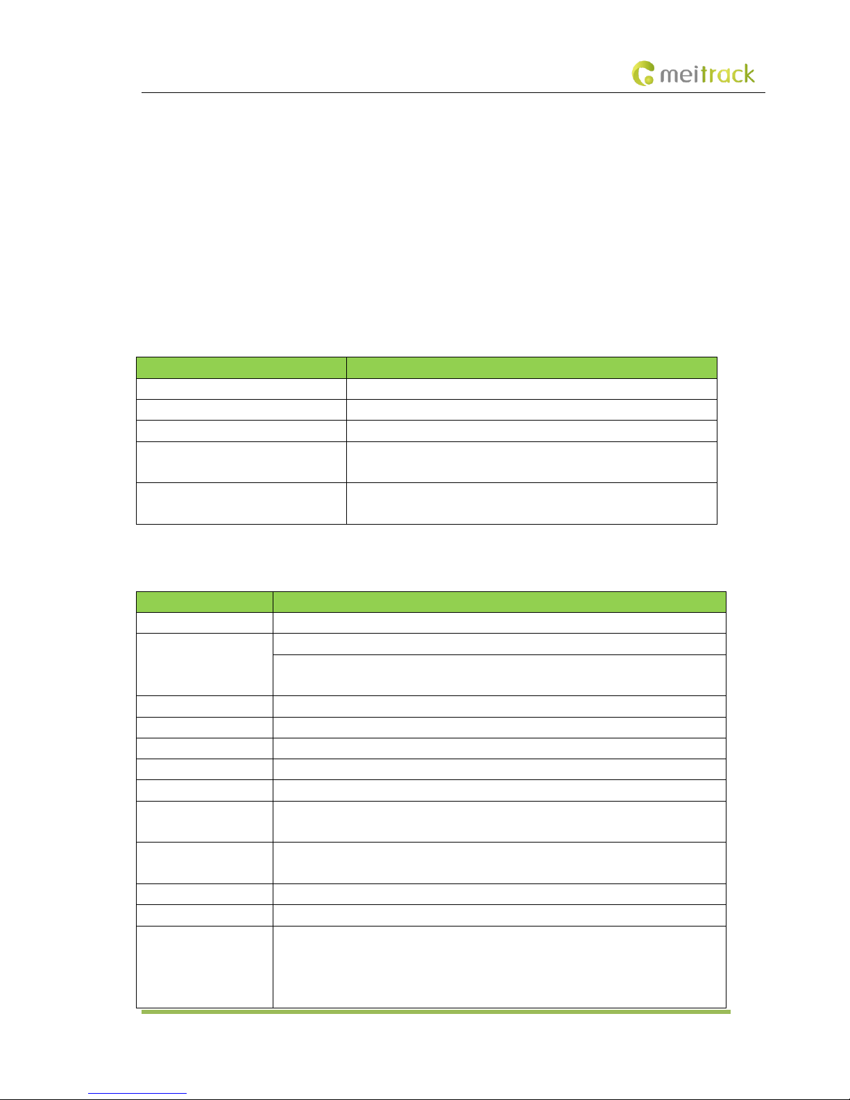
3.2 Specifications
Item
Specifications
Dimension
80.5 mm x 60 mm x 23.5 mm
Weight
Without an external GPS antenna: 100g
With an external GPS antenna: 122g
Battery weight: 8g
I/O power cable length
50 cm
Power supply
DC 11–36 V/1.5 A
Power consumption
Current in standby mode: 65mA
Operating temperature
-20°C to 80°C
Operating humidity
5% to 95%
LED indicator
Green indicator showing the GSM signal
Blue indicator showing the GPS signal
Button/Switch
1 upgrade button (used to manually upgrade the firmware)
1 power button
Memory
8 MB buffer
Sensor
3D acceleration sensor (for wake-up by vibration and towing alarms)
Frequency band
T366G-E:
UMTS/HSDPA: 900/2100 MHz
GSM/GPRS: 900/1800 MHz
T366G-A:
Page 7
MEITRACK T366G User Guide
Copyright © 2016 Meitrack Group All rights reserved. - 7 -
UMTS/HSDPA: 850/1900 MHz
GSM/GPRS: 850/900/1800/1900 MHz
T366G-T:
UMTS/HSDPA: 850/2100 MHz
GSM: 850/900/1800/1900 MHz
Note: Select proper device according to the local frequency band.
GPS sensitivity
-161 dB
Positioning accuracy
2.5m
I/O port
2 digital inputs (input 1: negative trigger by default, but can be configured as positive
trigger; input 2: positive trigger, connected engine detection by default)
1 analog detection input (0–30 V)
1 output
1 USB port
1 1-wire interface
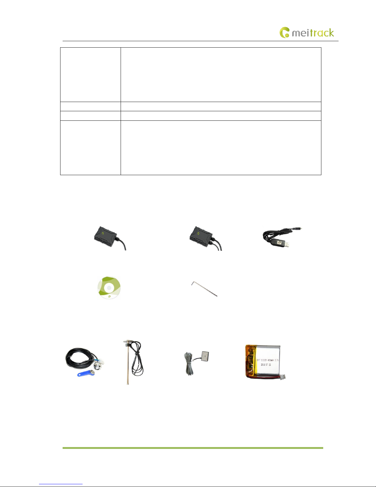
4 T366G and Accessories
T366G and standard accessories:
T366G (without an external GPS antenna)
T366G (with an external GPS antenna)
USB cable
CD
L wrench
Optional accessories:
iButton
A53 fuel sensor
A52 digital temperature sensor
Battery
Page 8
MEITRACK T366G User Guide
Copyright © 2016 Meitrack Group All rights reserved. - 8 -
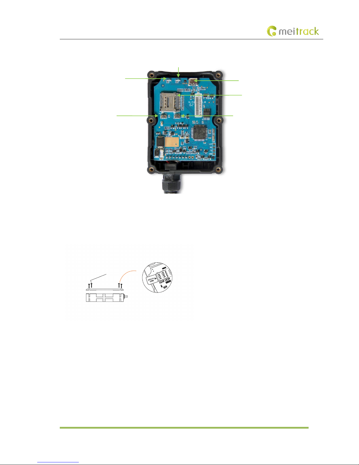
5 Device Panel
6 First Use
6.1 Installing the SIM Card
1. Use the screwdriver to open the back cover.
2. Insert the SIM card into the card slot (card chip facing down).
3. Close the cover, and tighten the screws.
Note:
Power off the device before installing the SIM card.
Ensure that the SIM card has sufficient balance.
Ensure that the phone card PIN lock has been closed properly.
Ensure that the SIM card in the device has subscribed the caller ID service if you want to use your authorized phone
number to call the device.
SIM card slot
Firmware upgrade button
Power button
GSM indicator
USB port
GPS indicator
Page 9
MEITRACK T366G User Guide
Copyright © 2016 Meitrack Group All rights reserved. - 9 -
6.2 LED Indicator
Press and hold down the power button for 3–5 seconds to start the device.
GPS Indicator (Blue)
Blink (every 0.1 second)
The device is being initialized or the battery power is low.
Blink (0.1 second on and 2.9 seconds off)
A GPS signal is received.
Blink (1 second on and 2 seconds off)
No GPS signal is received.
GSM Indicator (Green)
Steady on
A call is coming in or a call is being made.
Blink (every 0.1 second)
The device is being initialized.
Blink (0.1 second on and 2.9 seconds off)
A base station signal is received.
Blink (1 second on and 2 seconds off)
No base station signal is received.
6.3 Device Configuration
6.3.1 Installing the USB Driver
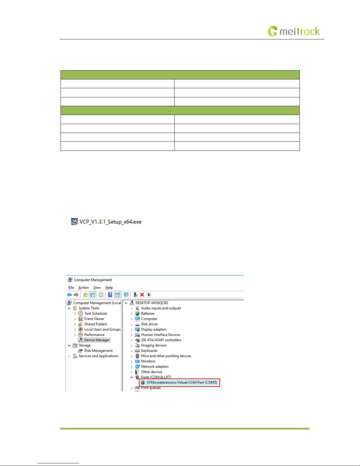
1. Decompress the stsw-stm32102.zip file provided by Meitrack, locate the following file, and install the USB driver on a
computer with 64-bit Windows system.
2. After the installation is finished, connect the tracker to the computer by USB cable. If STMicroelectronics Virtual COM
Port (COM5) is displayed on the Computer Management page, the driver is installed successfully.
Note: Please power on the tracker and then connect the tracker to the computer by USB cable. Otherwise, Meitrack
Manager will be unavailable.
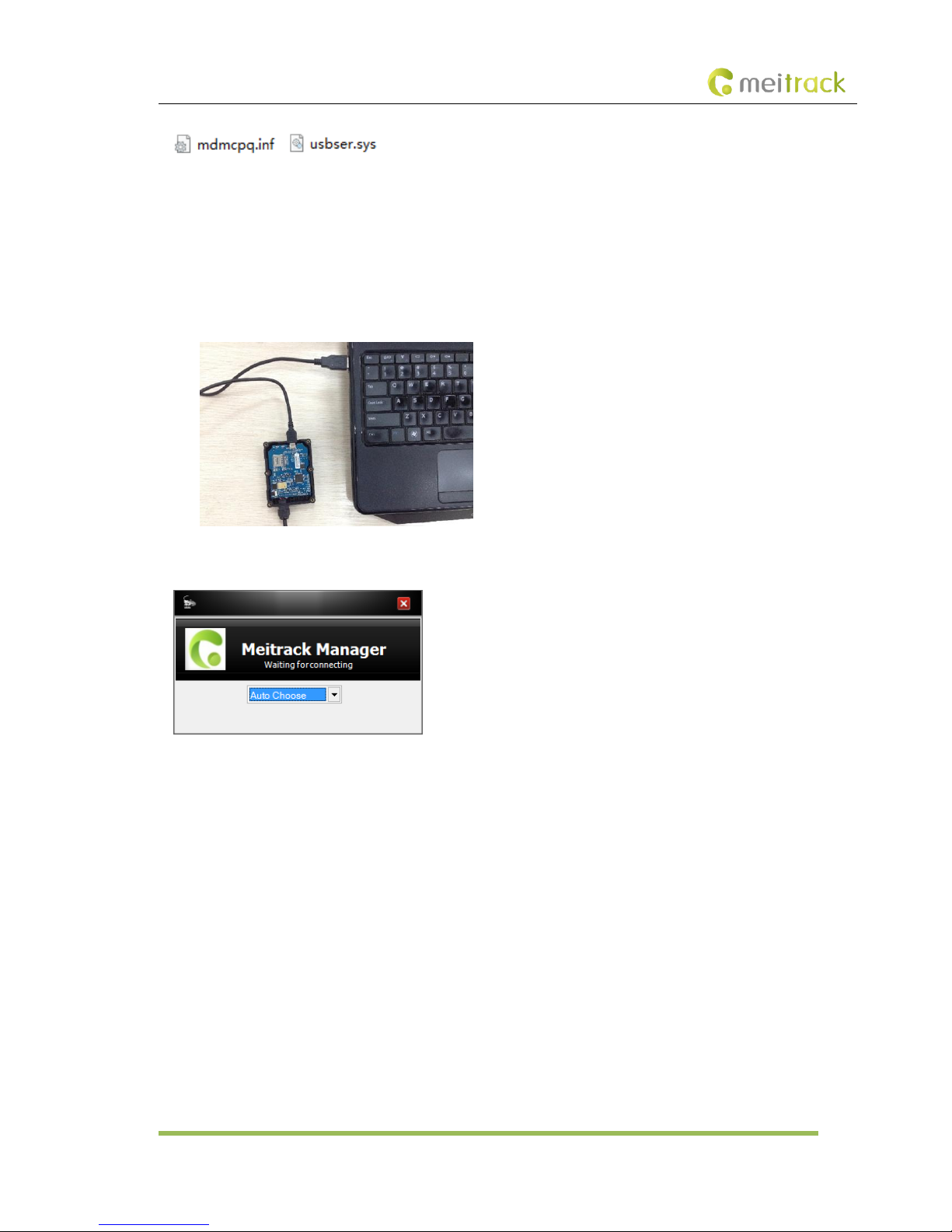
Note: After you finish the driver installation, if the preceding figure is not displayed, copy the mdmcpq.inf file to the
c:/windows/inf/ directory and usbser.sys file to the C:/windows/system32/drivers/ directory. Then restart the computer.
Page 10
MEITRACK T366G User Guide
Copyright © 2016 Meitrack Group All rights reserved. - 10 -
6.3.2 Configuring Device Parameters by Meitrack Manager
This section describes how to use Meitrack Manager to configure the device on a computer.
Procedure:
1. Install the USB-to-serial cable driver and Meitrack Manager.
2. Connect the device to a computer by using the USB-to-serial cable.
3. Run Meitrack Manager, then the following dialog box will appear:
4. Turn on the device, then Meitrack Manager will detect the device model automatically and the parameter page will
appear accordingly.
For details about MEITRACK Manager, see the MEITRACK Manager User Guide.
6.4 Tracking by Mobile Phone
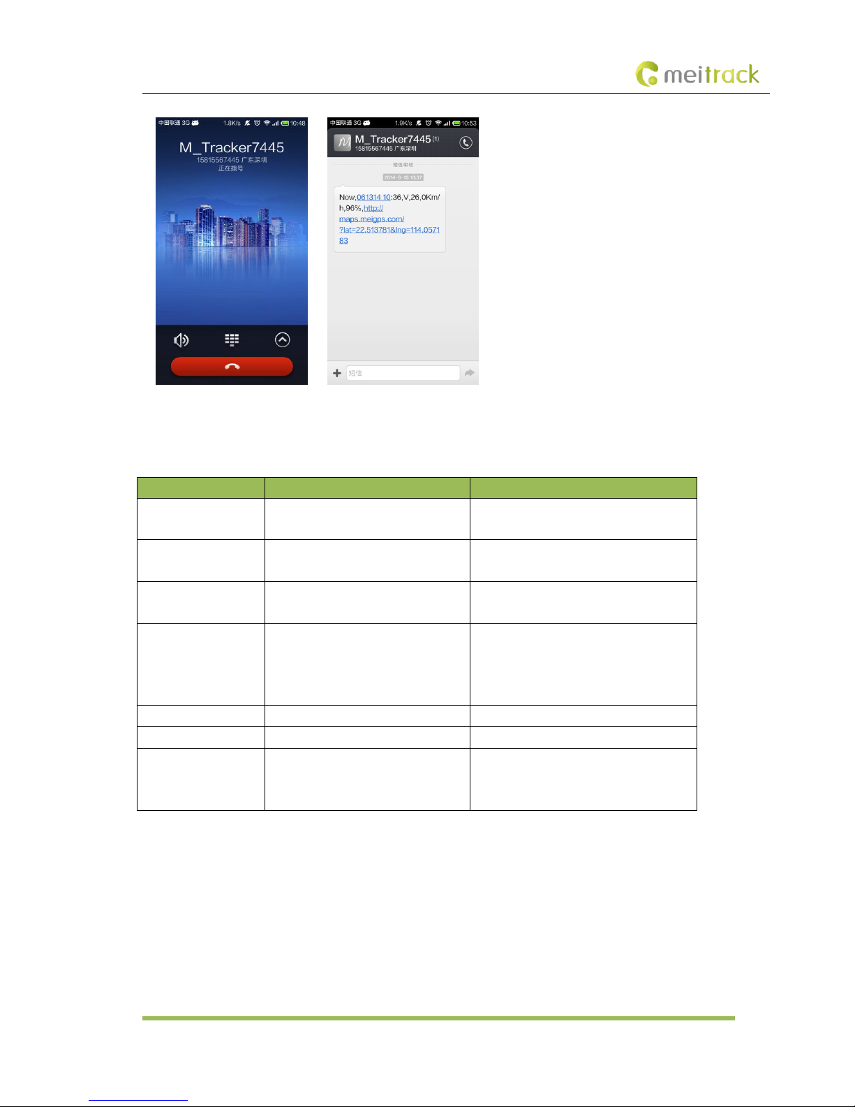
Call or send the 0000,A00 command by SMS to the device SIM card number. The device will reply an SMS with a map link.
Click the SMS link. The device's location will be displayed on Google Maps on your mobile phone.
Note: Ensure that the device SIM card number has subscribed the caller ID service. Otherwise, the tracking function by mobile
phone will be unavailable.
Page 11
MEITRACK T366G User Guide
Copyright © 2016 Meitrack Group All rights reserved. - 11 -
SMS example:
Now,061314 10:36,V,26,0Km/h,96%,http://maps.meigps.com/?lat=22.513781&lng=114.057183
The following table describes the SMS format:
Parameter
Description
Remarks
Now
Indicates the current location.
SMS header: indicates the current location
or the alarm type.
061314 10:36
Indicates the date and time in
MMDDYY hh:mm format.
None
V
The GPS is invalid.
A = Valid
V = Invalid
26
Indicates the GSM signal strength.
Value: 1–32
The larger the value is, the stronger the
signal is. If the value is greater than 12,
GPRS reaches the normal level.
0Km/h
Indicates the speed.
Unit: km/h
96%
Indicates the remaining battery power.
None
http://maps.meigps.co
m/?lat=22.513781&lng
=114.057183
Indicates the map link.
Latitude: 22.513781
Longitude: 114.057183
None
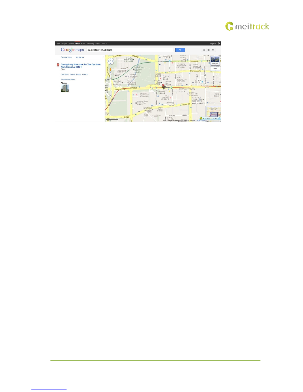
If your mobile phone does not support HTTP, enter the latitude and longitude on Google Maps to query a location.
Page 12
MEITRACK T366G User Guide
Copyright © 2016 Meitrack Group All rights reserved. - 12 -
6.5 Common SMS Commands
6.5.1 Real-Time Location Query – A00
SMS sending: 0000,A00
SMS reply: Now,Date and time,Positioning status,GSM signal strength,Speed, Remaining battery power,Map link
Description: This command is used to query tracker's current location.
Example:
Sending: 0000,A00
Reply: Now,160721 16:40,V,12,56Km/h,97%,http://maps.meigps.com/?lat=22.513015&lng=114.057235
6.5.2 Setting Authorized Phone Numbers – A71
SMS sending: 0000,A71,Phone number 1,Phone number 2,Phone number 3
SMS reply: IMEI,A71,OK
SMS reply:
Phone number: A phone number has a maximum of 16 bytes. If no phone numbers are set, leave them blank. Phone numbers
are empty by default.
Phone number 1/2/3: Set these phone numbers to authorized phone numbers. When you call the tracker by using these phone
numbers, you will receive SMS notification about the location, geo-fence alarm and low power alarm and SMS notification or a
call about the unauthorized door open and unauthorized ignition.
If you need to delete all authorized phone numbers, send 0000,A71.
Example:
Sending: 0000,A71,13811111111,13822222222,13833333333
Reply: 353358017784062,A71,OK
6.5.3 Setting the Smart Sleep Mode – A73
SMS sending: 0000,A73,Sleep level
SMS reply: IMEI,A73,OK
Description:
When the sleep level is 0, the sleep mode is disabled (default).
Page 13

MEITRACK T366G User Guide
Copyright © 2016 Meitrack Group All rights reserved. - 13 -
When the sleep level is 1, the tracker enters the normal sleep mode. The 3G module always works, and the GPS module
occasionally enters the sleep mode. The tracker works 25% longer in the normal sleep mode than that in the normal working
mode. This mode is not recommended for short interval tracking; this will affect the route precision.
When the sleep level is 2, the tracker enters the deep sleep mode. If no event (SOS, button changes, incoming calls, SMSs, or
vibration) is triggered after five minutes, the GPS module will stop working, and the 3G module will enter sleep mode. Once a n
event is triggered, the GPS and 3G modules will be woken up.
Note: In any condition, you can use an SMS command to disable the sleep mode, and then the tracker exits the sleep mode and
returns back to the normal working mode.
Example:
Sending: 0000,A73,2
Reply: 353358017784062,A73,OK
For details about SMS commands, see the MEITRACK SMS Protocol.
Note:
1. The default SMS command password is 0000. You can change the password by using Meitrack Manager and SMS
command.
2. The device can be configured by SMS commands with a correct password. After an authorized phone number is set, only
the authorized phone number can receive the preset SMS event report.
7 Logging In to MS03 Tracking System
Visit http://ms03.trackingmate.com, enter the user name and password, and log in to the MS03. (Purchase the login account
from your provider.)
For more information about how to add a tracker, see the MEITRACK GPS Tracking System MS03 User Guide (chapter 4 "Getting
Started").
The MS03 supports the following functions:
Track by time interval or distance.
Query historical traces.
Set polygon geo-fences.
Bind driver and vehicle information.
View various reports.
Send commands in batches.
Support OTA updates.
For details, see the MEITRACK GPS Tracking System MS03 User Guide.
8 Installing the T366G
8.1 Installing an I/O Cable
8.1.1 Interface Definition
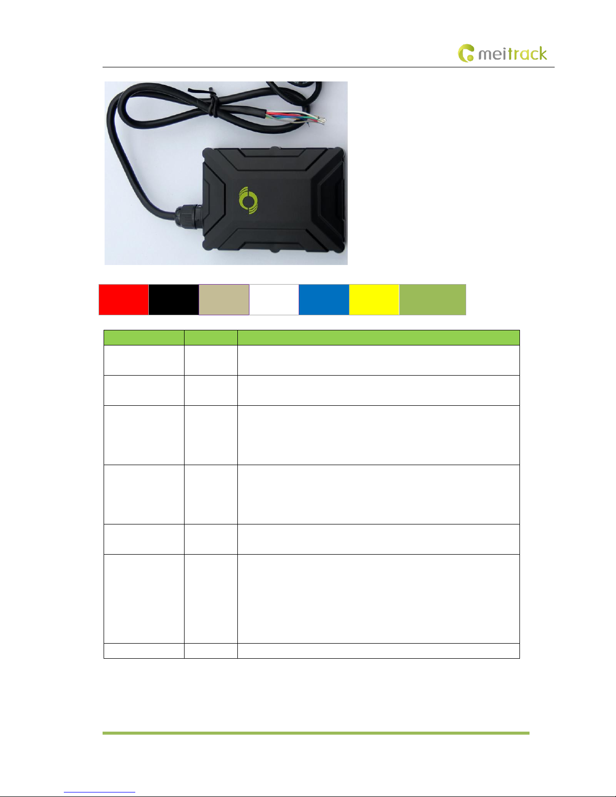
The I/O cable is a 7-pin cable, including the power, analog input, and negative/positive input and output interfaces.
Page 14
MEITRACK T366G User Guide
Copyright © 2016 Meitrack Group All rights reserved. - 14 -
1
Power (+)
2
GND (-)
3
Input 1 (-)
4
Input 2 (+)
5
AD input 1
6
Output 1
7
1-wire interface
Pin Number
Color
Description
1 (Power +)
Red
Positive charge of the power input, connected to the positive charge of the
vehicle battery. Input voltage: 11–36 V. 12 V is recommended.
2 (GND)
Black
Ground wire, connected to the negative charge of the vehicle battery or to the
negative terminal.
3 (Input 1)
Grey
Digital input, negative trigger by default. The port can be configured as
positive trigger.
Connect to a door trigger signal cable to detect vehicle door status. (Most
Chinese, Korean, and Japanese cars are negative edge-triggered.)
4 (Input 2)
White
Digital input, positive trigger
Connect to the vehicle ACC cable by default to detect the vehicle ACC status.
Connect to a door trigger signal cable to detect vehicle door status. (Most
Europe and American cars are positive edge-triggered.)
5 (AD input 1)
Blue
Analog input with 12-bit resolution and valid voltage 0–30 V.
Connect an external sensor, such as the fuel sensor.
6 (Output 1)
Yellow
Valid: low level (0 V)
Invalid: open collector
Maximum voltage for output open collector (invalid): 60 V
Maximum current for output low level (valid): 500 mA
Connect to an external relay to remotely cut off the vehicle fuel cable or
engine power supply.
7 (1-wire interface)
Green
Connect to the iButton and other devices supporting 1-wire protocol.
Page 15
MEITRACK T366G User Guide
Copyright © 2016 Meitrack Group All rights reserved. - 15 -
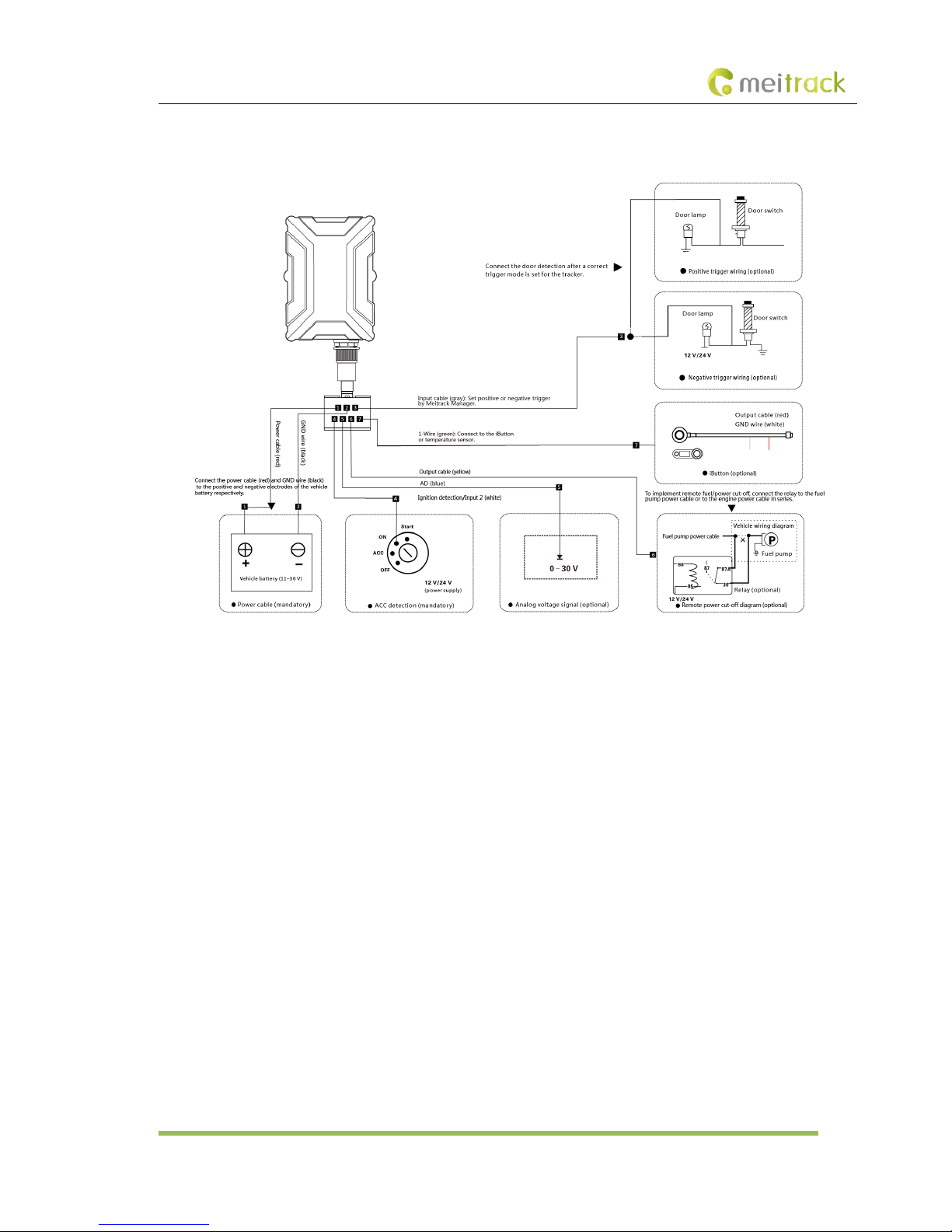
8.1.2 Wiring Diagram
8.2 Mounting the T366G
Mount the device in the vehicle by cable tie.
Note: Do not install it at a metal covered place.
If you have any questions, do not hesitate to email us at [email protected].
 Loading...