

Page 1
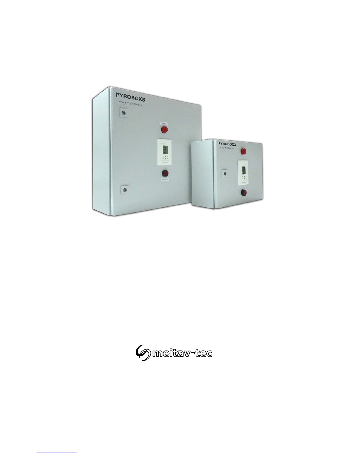
PYROBOX3-TRACE
PYROBOX3C-TRACE
PYROBOX5-TRACE
Installation and Operating manual
Page 2

Index
Introduction…………………………………………………………………...…….3
PYROBOX Installation notes ……...…………...………………………………..4
Wiring the PYROBOX5………….……………………………………………….5
Wiring the PYROBOX3C…….….………………………………………………. 6
Wiring the PYROBOX3………….……………………………………………….7
Operating instructions…………………………………………………………….8
Turning the system ON and OFF………………………………………………. 8
Selecting temperature scale……………………………………………………..8
Selecting Automatic or Manual mode…………………………………………. 8
Heaters indication………………………………………………………………... 8
Snow flake icon and digital time indication……………………………………. 8
Technician settings……………………………………………………………….. 9
Enter technician settings mode…………………………………………...……. 9
P01 - Temperature set point…………………………………………………….9
P02 - Lower limit temperature for heating…………………………………….. 10
P03 -Time delay before stopping the heaters………………………………….10
P04 - Manual mode ON time…………………………………………………….11
P05 - Heaters cycle and splitting time………………………………………….11
P06 - Enable/Disable 2
nd
temperature sensor (Aquastat)…………………… 11
P07 - Heater outputs logic (by Temperature sensor or by Aquastat)…..….. 12
P08 – MODBUS MAC Address for building automation (option)…….…...…12
P09 - Test conditions mode……………………………………………………..13
Save changes and return to normal display…………………………...…..…. 13
Restore default values…………………………………………………………….13
DIP Switch settings……………………………………………………………….. 14
DIP switch S2 - Short measuring times (test only)…………………………... 14
DIP switches S3 and S4 – heaters sequencing logic………………………...14
Enable/Disable zones……...……………………………………………………... 15
Temperature reading errors……………………………………………………...16
MODBUS communication error……………………..…………………………..16
Temperature sensor not connected or short circuit ……...…………………..1 6
Appendix 1 - Calibrating and testing the internal GFCI……………………..17
Tel: (856) 2882882
Tel: +972-3-9626462
Fax: +972-3-9626620
PYROBOX3/3C/5
-TRACE
Owner’s manual & Technician Settings
Pg. 2
Page 3
Introduction
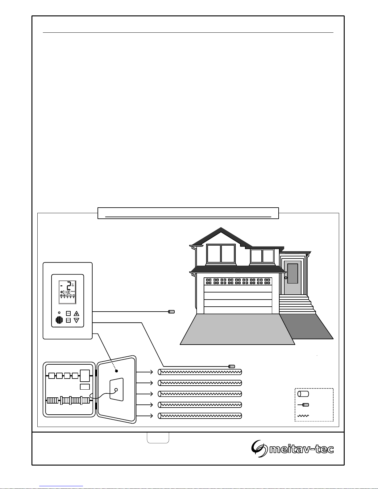
The PYROBOX3/3C/5-TRACE power boxes together with the PYROTRACE controller and interface
panel, offer smart and easy control for HEAT TRACING SYSTEMS.
It can operate up to 4 heating zones and one auxiliary zone, with selectable sequencing method.
Typical applications include pipes, valves and gutters.
The backlit LCD screen provides full interface and information to the system status.
The Use of several zones staggering allow covering longer pipes length with less available electrical
power.
The PYROTRACE offers various operating and programming options such as:
- Switchable temperature scales (°F or °C) - Adjustable Lower ambient temperature limit to stop
- Both Automatic and Manual modes heaters (lockout)
- Adjustable heaters cycle and splitting times - Energy saving temperature limit
- Adjustable heaters hold on off delay - Commissioning/Test environment
Tel: (856) 2882882
Tel: +972-3-9626462
Fax: +972-3-9626620
PYROBOX3/3C/5
-TRACE
Owner’s manual & Technician Settings
Pg. 3
Temperature sensor
PYROBOX3/5-TRACE
PYROTRACE
Zone 1
PYROTRACE General system layout with PYROBOX3/5
Zone 2
Zone 3
Zone 4
Zone 5
Aquastat sensor (option)
Pipe
Sensor
Heater
Page 4
Tel: (856) 2882882
Tel: +972-3-9626462
Fax: +972-3-9626620
PYROBOX3/3C/5
-TRACE
Owner’s manual & Technician Settings
Pg. 4
PYROBOX Series Installation
Installation notes
Familiarize yourself with the markings, warnings, components and terminology.
The PYROBOX power boxes and its accessories must be installed by a qualified electrician in
accordance with local regulations and the requirements of the NEC (NFPA 72 ) and the CEC part 1.
WARNING: Ensure the power is disconnect from all circuits before mounting the power box and
making any connections. Contact with components carrying hazardous voltage can cause electric
shock and may result in severe personal injury or death.
Installer must ensure the installation of approved disconnect means, for all power supply
circuits feeding this unit.
The power boxes are suitable for indoor wall mount installation only.
Ensure wiring according to the provided schematics using copper conductors only.
Make sure the wire gauge (AWG) is suitable for the circuit amperage draw, as specified in the
NEC/CEC table 1.
Ensure that the main breakers (fuses) are suitable for the heating systems rating (80% load).
Grounding means must comply with local regulations and CEC/NEC.
Ensure that the heating system/de-icing system connected to this unit complies with the UL 499 or
UL 515 & CSA 22.2 # 130.3 standard and is certified / listed by an NRTL.
Ensure that all wiring is rated for the application at 60°C (140°F as per UL 515 CSA 22.2 #130
clause 12 table 12.1.
Ensure that any holes punched for conduit are to compromise the integrity of the enclosure ratings.
Ground fault circuit interrupter (GFCI)
The ground fault interrupter/residual current detector installed in this system is a Non class A GFCI,
intended for equipment protection.
Familiar yourself with its operation and required setting.
At installation and commissioning stage use a calibrated milliamp meter to read and record the
heating systems natural leakage.
Set the GFI/RCD to no more than 30 milliamps higher than that reading.
This step might have to be repeated a few times, to avoid nuisance tripping.
The GFCI should be tested monthly. Please refer to the calibration and testing instructions in
appendix 1 of this manual.
PLEASE READ THIS MANUAL AND THE SAFETY WARNINGS CAREFULLY BEFORE INSTALLING
AND USING THE CONTROLLER AND SAVE IT FOR FUTURE USE
Page 5
Wiring the PYROBOX5-TRACE
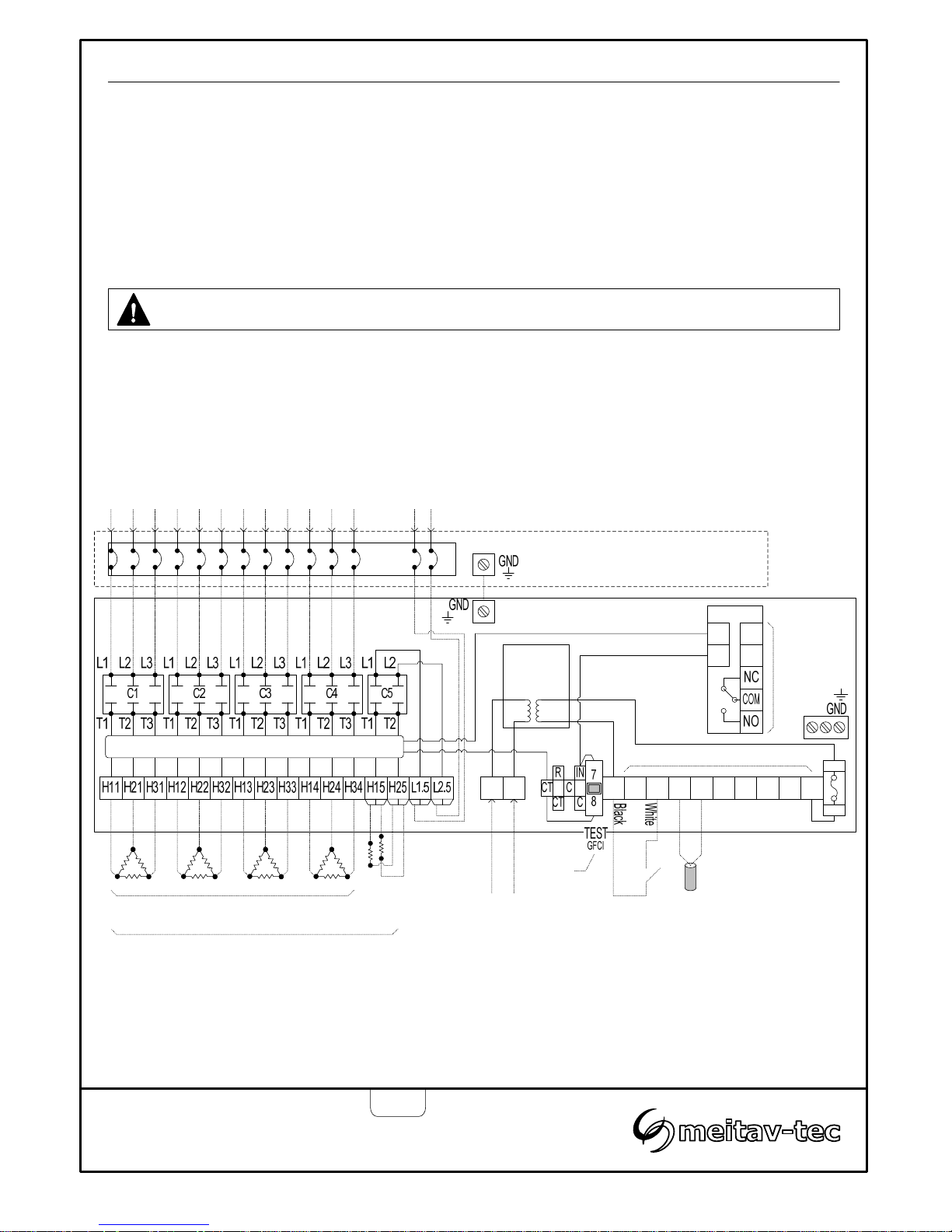
Heater load connection
Provide 3-Phase contactors C1, C2, C3 and C4 with up to 600 VAC, 50 AMP Maximum per pole.
Provide contactor C5 with with up to 300 VAC, 30 AMP.
Make sure the wire gauge (AWG) is suitable for the circuit Amperage draw, as specified in the NEC/
CEC table 1.
Main supply for the power box
Provide terminals L1, N1 with 120 VAC supply.
Connection to 3
rd
party ice/snow sensor (GIT-1 / CIT-1 / SIT/6E) - option
3-wire shielded cable
Up to 2,000 ft (609 m) using 12 AWG 3-wire shielded cable.
Up to 500 ft (152 m) using 18 AWG 3-wire shielded cable.
Tel: (856) 2882882
Tel: +972-3-9626462
Fax: +972-3-9626620
PYROBOX3/3C/5
-TRACE
Owner’s manual & Technician Settings
Pg. 5
21 AC C RC BRL1 N1 R
GFCI
Main
supply
120 VAC
F-5A
R
ININ1
2
Current transformer
Transformer
130VA
120/24VAC
300 VAC max.
30 AMP max.
Heater load connection
L1,L2,L3 - 600 VAC max.
50 AMP max. per pole
Branch circuit protection and disconnect
provided by installer
Max. 60A
Aquastat
(option)
PYROULS
(By Meitav-tec)
Internal connections
Internal connections
Caution: Incorrect voltage may cause fire or seriously damage the unit.
Important!
If the heaters are connected in star, the neutral
must pass through the internal current transformer
ring and the external branch circuit protection.
A
1
A
C1
B
1
B
C
A
1
A
C1
B
1
B
C
A
1
A
C1
B
1
B
C
A
1
A
C1
B
1
B
C
See
Appendix 1
Page 6
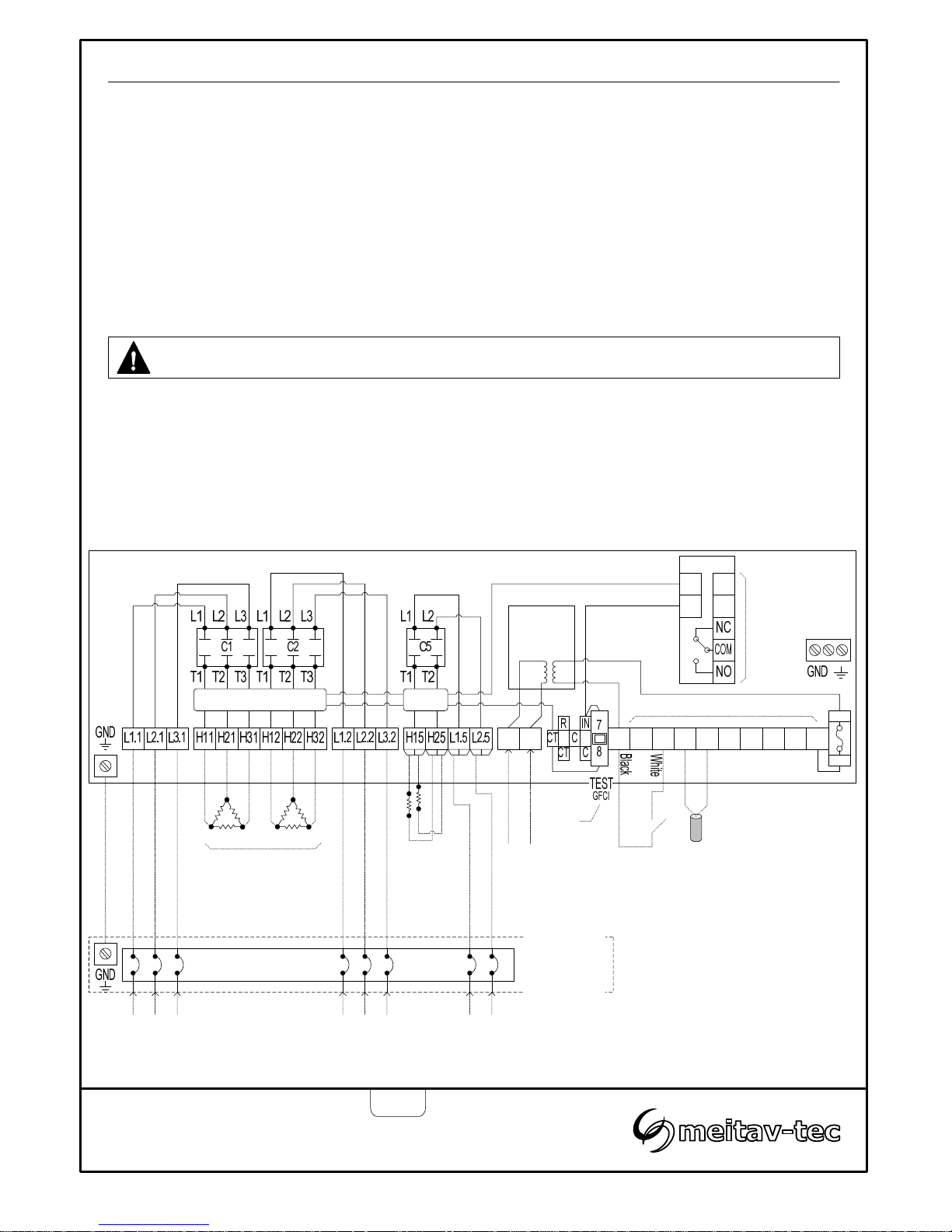
Wiring the PYROBOX3C-TRACE
Heater load connection
Provide 3-Phase contactors C1 and C2 with up to 600 VAC, 50 AMP Maximum per pole.
Provide contactor C5 with with up to 300 VAC, 30 AMP.
Make sure the wire Gauge (AWG) is suitable for the circuit Amperage draw, as specified in the NEC/
CEC table 1.
Main supply for the power box
Provide terminals L1, N1 with 120 VAC supply.
Connection to 3
rd
party ice/snow sensor (GIT-1 / CIT-1 / SIT/6E) - option
3-wire shielded cable
Up to 2,000 ft (609 m) using 12 AWG 3-wire shielded cable.
Up to 500 ft (152 m) using 18 AWG 3-wire shielded cable.
Tel: (856) 2882882
Tel: +972-3-9626462
Fax: +972-3-9626620
PYROBOX3/3C/5
-TRACE
Owner’s manual & Technician Settings
Pg. 6
Caution: Incorrect voltage may cause fire or seriously damage the unit.
21 AC C RC BRL1 N1 R
GFCI
F-5A
R
ININ1
2
Current transformer
Transformer
130VA
120/24VAC
Heater load connection
L1,L2,L3 - 600 VAC max.
50 AMP max. per pole
Internal connections
Main
supply
120 VAC
Branch circuit
protection and
disconnect
provided by
installer
Max. 60A
Internal connections
Heater load
connection
300 VAC max.
30 AMP max.
C.T
Important!
If the heaters are connected in star, the
neutral must pass through the internal
current transformer and the external
Branch circuit protection.
A
1
A
C1
B
1
B
C
A
1
A
C1
B
1
B
C
See
Appendix 1
Aquastat
(option)
PYROULS
(By Meitav-tec)
Page 7
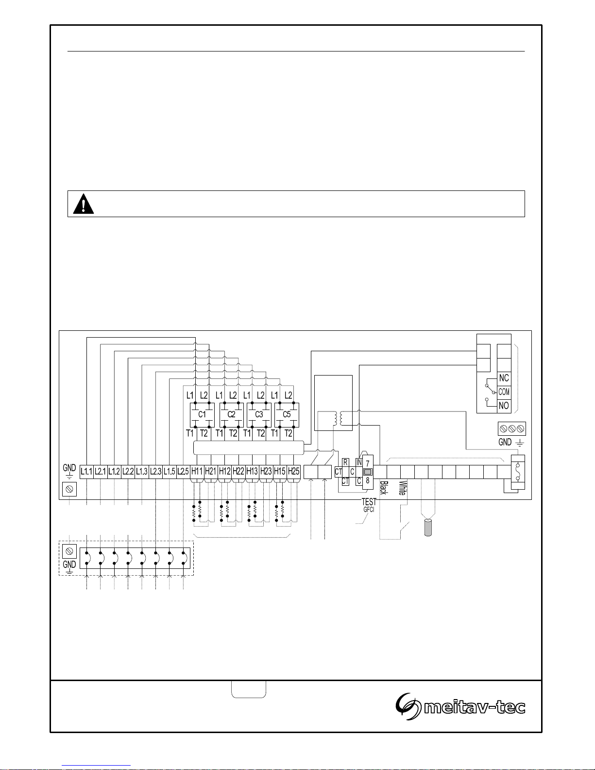
Wiring the PYROBOX3-TRACE
Heater load connection
Provide contactors C1, C2, C3 and C4 with up to 300 VAC, 30 AMP.
Make sure the wire Gauge (AWG) is suitable for the circuit Amperage draw, as specified in the NEC/
CEC table 1.
Main supply for the power box
Provide terminals L1, N1 with 120 VAC supply.
Connection to 3
rd
party ice/snow sensor (GIT-1 / CIT-1 / SIT/6E) - option
3-wire shielded cable
Up to 2,000 ft (609 m) using 12 AWG 3-wire shielded cable.
Up to 500 ft (152 m) using 18 AWG 3-wire shielded cable.
Tel: (856) 2882882
Tel: +972-3-9626462
Fax: +972-3-9626620
PYROBOX3/3C/5
-TRACE
Owner’s manual & Technician Settings
Pg. 7
21 AC C RC BRL1 N1 R
GFCI
Main
supply
120 VAC
F-5A
R
ININ1
2
Current transformer
Transformer
130VA
120/24VAC
Heater load connection
300 VAC max.
30 AMP max.
Internal connections
Internal connections
Caution: Incorrect voltage may cause fire or seriously damage the unit.
Branch circuit protection
and disconnect provided
by installer. Max. 60A
Important!
If the heaters are connected in star, the neutral must
pass through the internal current transformer and the
external Branch circuit protection.
See
Appendix 1
Aquastat
(option)
PYROULS
(By Meitav-tec)
Page 8
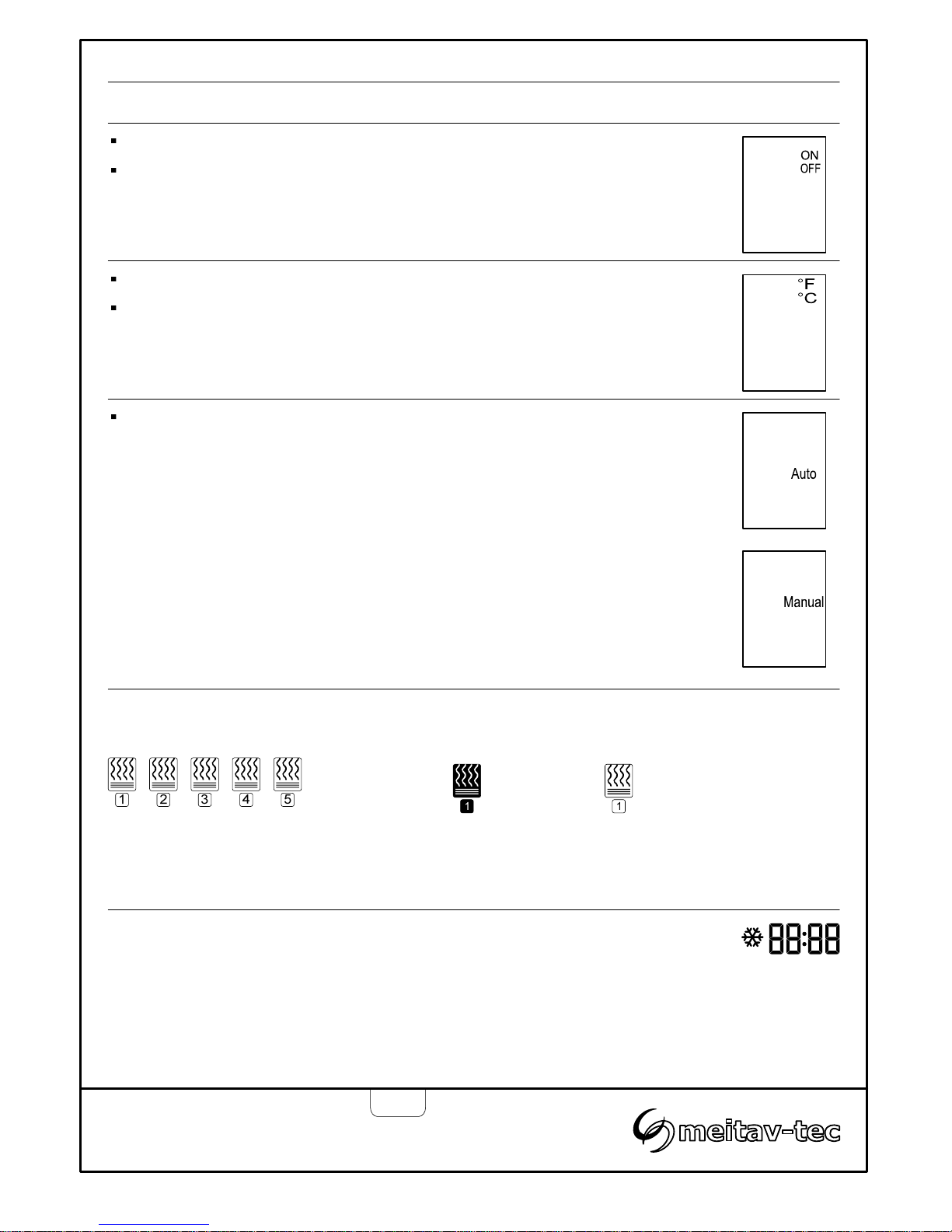
Operating instructions
Turning the system ON and OFF
Press the [SELECT] button to switch between modes:
“Automatic” Heating will start and stop automatically depending on the set point
and ambient temperatures.
“Manual ON” Heating will start regardless of the set point and ambient
temperatures and will stop after a preset time (pls. refer to the
“Manual ON” section in the tech. settings).
Note: Mode will always return to “Automatic” after switching the unit OFF and ON.
Press and hold the [ON] button for 0.5 seconds to turn the system ON or OFF.
The words “ON” or “OFF” will appear on display.
Selecting Automatic or Manual mode
Selecting temperature scale
Press the [+] button for Celsius.
Press the [-] button for Fahrenheit.
Tel: (856) 2882882
Tel: +972-3-9626462
Fax: +972-3-9626620
PYROBOX3/3C/5
-TRACE
Owner’s manual & Technician Settings
Pg. 8
Heaters indication
Heater ON Heater OFF
The number beneath the heater icon
indicate the heater stage (1 to 5).
Stg.1Stg.2Stg.3Stg.4Stg.
5
Black icon – Heater ON
White icon – Heater OFF
A solid snow flake icon will appear on display during normal heaters operation.
Snow flake icon and digital time indication
A blinking snow flake icon will appear on display during heaters off delay or when manual mode is
activated. The digital clock will count down the remaining time until the heaters are turned off.
The snow flake icon will disappear from display as long as the heaters are turned off.
Page 9
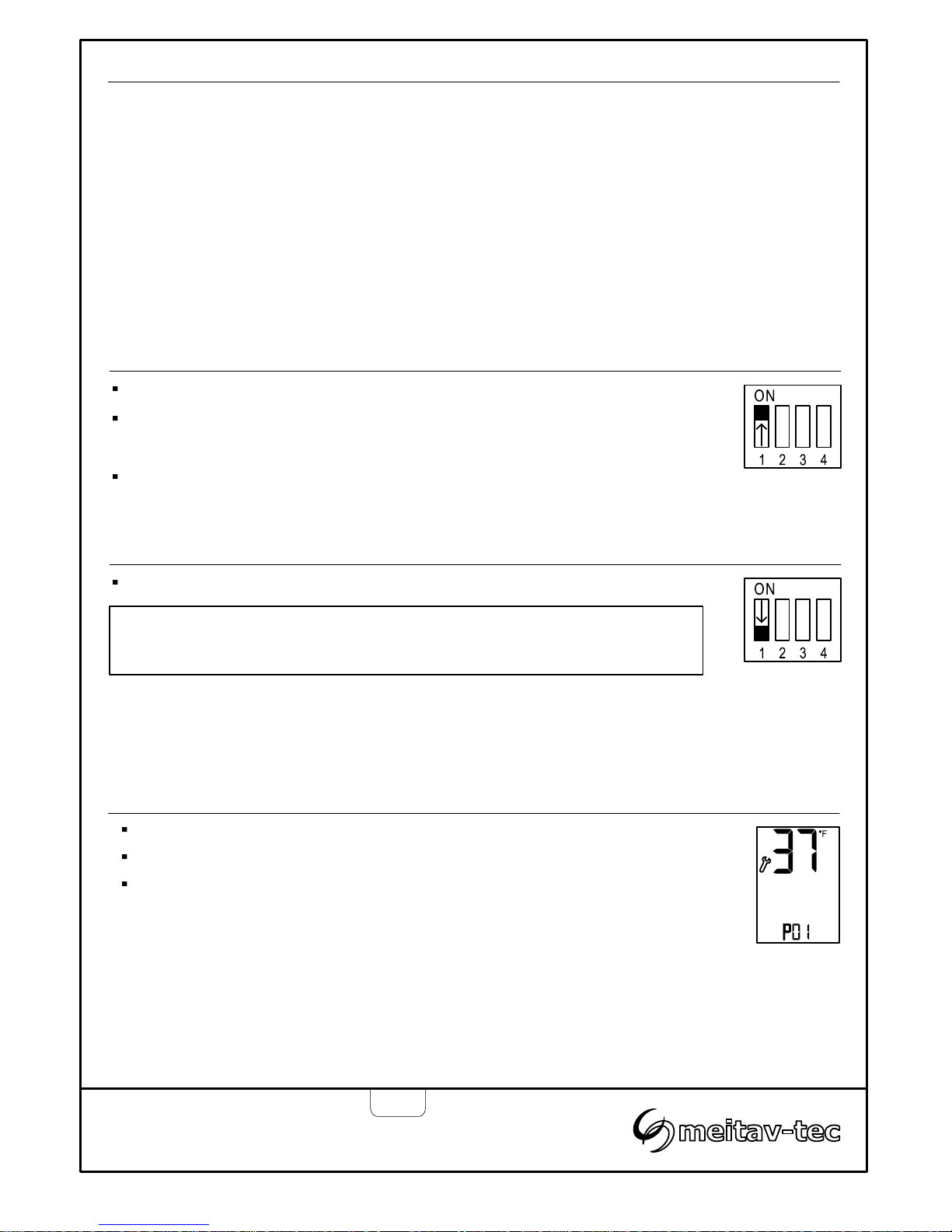
P01 - Temperature set point
Move DIP switch S1 located on the side of thermostat to ON position.
“P01” and the temperature set point will appear on display.
Use the [+] and [-] buttons to adjust the temperature set point.
Range: 5…60°F / -15…+15°C, Default: 37°F / 3°C
As long as the ambient temperature is lower than the temperature
set point P01, the PYROTRACE will turn ON.
Tel: (856) 2882882
Tel: +972-3-9626462
Fax: +972-3-9626620
PYROBOX3/3C/5
-TRACE
Owner’s manual & Technician Settings
Pg. 9
Temperature
set point
Technician settings
Use the technician settings mode to view and adjust the following parameters:
P01 Temperature set point
P02 Lower ambient temperature limit to stop
heaters
P03 Time delay before stopping the heaters
P04 ON time for manual mode
P05 Heaters cycle time / Splitting time
P06 Enable/Disable 2
nd
temperature sensor
logic (Aquastat)
P07 Heaters outputs logic
P08 MODBUS MAC Address for home
automation system (option)
P09 Commissioning / Test mode
Restore defaults
Move DIP switch S1 located on the side of thermostat to ON position.
Press the [SELECT] and [+] buttons simultaneously to move forward to the next
technician parameter.
Press the [SELECT] and [-] buttons simultaneously to return to the previous
technician parameter.
Enter technician settings mode
Enter technician
settings mode
Important: Changes made to technician parameters will not take effect as
long as DIP switch S1 is in ON position.
Save changes
and exit
technician
settings mode
Parameters:
Save changes and exit technician settings mode
Move DIP switch S1 located on the side of thermostat to OFF position.
Page 10
Technician settings (Cont’)
P03 -Time delay before stopping the heaters
Tel: (856) 2882882
Tel: +972-3-9626462
Fax: +972-3-9626620
PYROBOX3/3C/5
-TRACE
Owner’s manual & Technician Settings
Pg. 10
Press the [SELECT] and [+] buttons simultaneously.
“P03”, “dL” and the time delay before stopping the heaters (Hold ON) will
appear on display. The hours will blink.
Use the [+] and [-] buttons to adjust the hours of the time delay.
Range: 0000...9999 minutes Default: 120 minutes
Note 1. The time delay countdown will start when the ambient temperatures
rises above the set point temperature.
Note 2. The staggering sequence will continue during the time delay period.
Time delay
(minutes)
Cont’
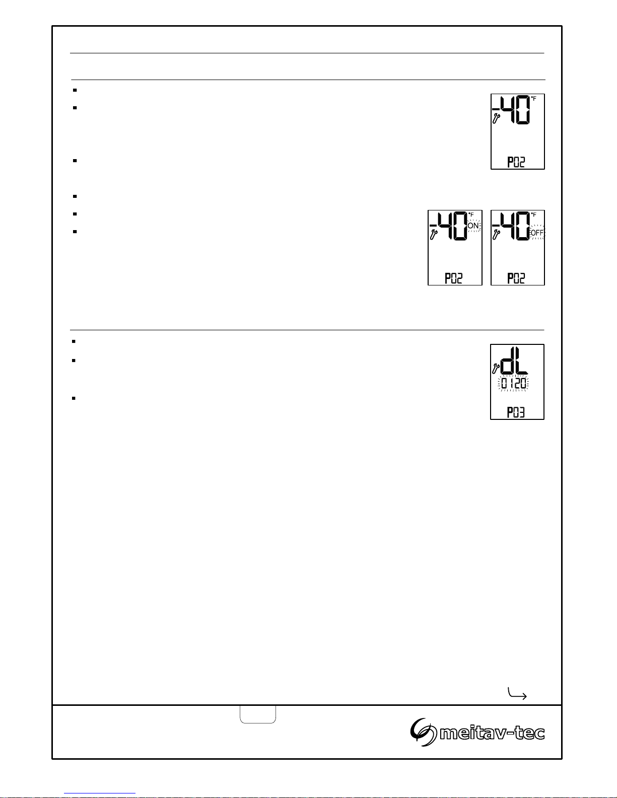
P02 - Lower limit temperature for heating
Press the [SELECT] and [+] buttons simultaneously.
“P02” and the low limit temperature will appear on display.
When the temperature on the temperature sensor drops below the low
temperature limit, the heating system will stop.
Use the [+] and [-] buttons to adjust the temperature set point.
Range: -40…+23°F / -40…-5°C Default: -40°F / -40°C
Press the [SELECT] and [+] buttons simultaneously again.
The word “ON” or “OFF” will appear on display.
Use the [+] and [-] buttons enable (ON) or disable (OFF) the P02
parameter.
If disabled, the heating system will operate without low temperature
limitations.
Low limit
Temperature
P02
enabled
P02
disabled
Page 11
Technician settings (Cont’)
Tel: (856) 2882882
Tel: +972-3-9626462
Fax: +972-3-9626620
PYROBOX3/3C/5
-TRACE
Owner’s manual & Technician Settings
Pg. 11
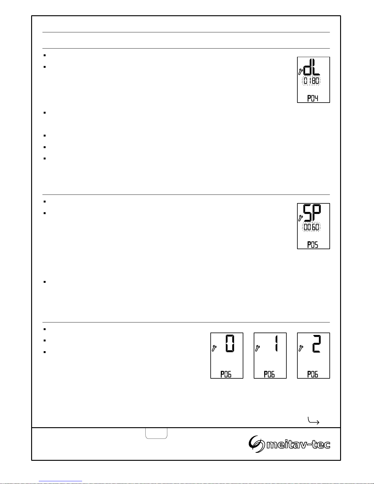
P05 – Heaters cycle and splitting time
Press the [SELECT] and [+] buttons simultaneously.
“P05”, “SP” and the splitting time will appear on display.
The minutes will blink.
The heaters cycle / splitting time parameter defines the working time of the
heaters when working in sequence.
Example: the splitting time is set to 10 minutes and 4 heaters work in
sequence, each heater will be ON for 2.5 minutes (10/4=2.5).
Use the [+] and [-] buttons to adjust the splitting time.
Range: 10...1999 minutes Default: 60 minutes.
Splitting time
Cont’
P06 – Enable/Disable Temperature sensor / Aquastat logic
Press the [SELECT] and [+] buttons simultaneously.
“P06” and the number “0” or “1” will appear on display.
Use the [+] and [-] buttons to select between:
“0” - Logic set by both TEMPERATURE SENSOR
and AQUASTAT (default).
“1” - Logic set by TEMPERATURE sensor only.
“2” - Logic set by AQUASTAT sensor only
Logic by
temperature
sensor only
Logic by
temperature
sensor and
aquastat
Logic by aquastat
sensor only
P04 - Manual mode ON time
Press the [SELECT] and [+] buttons simultaneously.
“P04”, “On” and the time “Manual ON” mode time period will appear on
display. The hours will blink.
The delay time parameter defines a time frame in which the heaters remain
ON after receiving an “Manual ON” command.
Use the [+] and [-] buttons to adjust the hours of the working time.
Range: 00...99 hours Default: 03 hours
Press the [SELECT] and [+] buttons simultaneously again.
The minutes will blink.
Use the [+] and [-] buttons to adjust the minutes of the working time.
Range: 00...59 minutes Default: 00 minutes
Manual ON
(minutes)
Page 12
Technician settings (Cont’)
Tel: (856) 2882882
Tel: +972-3-9626462
Fax: +972-3-9626620
PYROBOX3/3C/5
-TRACE
Owner’s manual & Technician Settings
Pg. 12
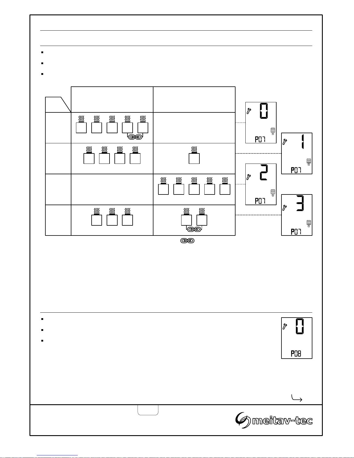
P07 - Heaters outputs logic (by TEMPERATURE SENSOR or by AQUASTAT SENSOR)
Press the [SELECT] and [+] buttons simultaneously.
“P07” and the figures “0”, “1”, “2” or “3” will appear on display.
Use the [+] and [-] buttons to define the logic of output 1-5 as follows:
Cont’
Temperature Sensor Aquastat Sensor
1
2
3
0 1 2 3 4 5
1 2 3 4 5
1 2 3 4 5
1 2 3 4 5
Option
P08 – MODBUS MAC Address
Press the [SELECT] and [+] buttons simultaneously.
“P08” and the MODBUS MAC Address will appear on display.
Use the [+] and [-] buttons to set the MAC Address of the unit.
Setting the MAC address for the unit will make it available through the home
automation system.
Range: 0 – 60.
Select “0” for NO COMMUNICATION system (default).
Linked heaters
Notes:
1. If option 2 is selected, the temperature display will remain blank.
2. If P06=1, only option “0” is available.
2. If P06=2, only option “2” is available.
MODBUS
MAC Address
Page 13
Technician settings (Cont’)
Tel: (856) 2882882
Tel: +972-3-9626462
Fax: +972-3-9626620
PYROBOX3/3C/5
-TRACE
Owner’s manual & Technician Settings
Pg. 13
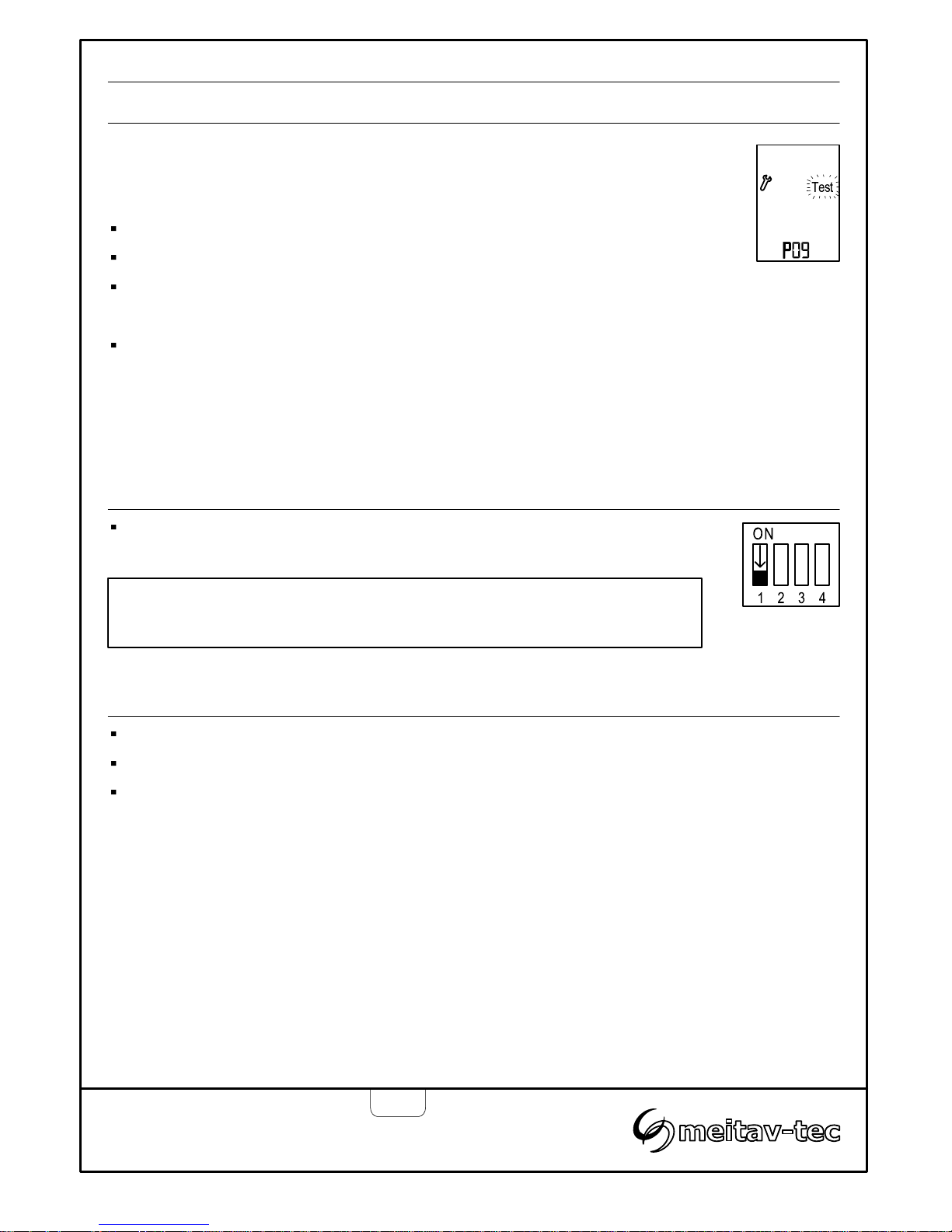
P09 - Test conditions mode / Technician commissioning mode
Turn ON test conditions to check the functionality of the system regardless of
temperature sensors parameters (i.e. during the summer).
In test conditions, the Ambient temperature is always -7°C/19°F.
Press the [SELECT] and [+] buttons simultaneously.
“P09” will appear on display. The hours will blink.
Use the [+] button to enter test/commissioning mode – the word “Test” will
appear on display.
Use the [-] button to manually exit test/commissioning mode – the word
“Test” will disappear from display.
Note: If the technician did not manually exit test/commissioning mode, the unit
will automatically return to normal mode after 5 hours.
Test
conditions
mode
Restore default values
Move DIP switch S1 to ON position.
Press and hold the [ON] button for 10 seconds. The thermostat will beep.
Move DIP switch S1 back to OFF position.
In order to save changes and return to normal display, move DIP switch S1 back to
OFF position.
Save changes and return to normal display
Important: Changes made to technician parameters will not take effect as
long as DIP switch S1 is in ON position.
Page 14
Technician settings (Cont’)
Tel: (856) 2882882
Tel: +972-3-9626462
Fax: +972-3-9626620
PYROBOX3/3C/5
-TRACE
Owner’s manual & Technician Settings
Pg. 14
Use DIP switch S2 to short the
- “ON” - Short measuring times – for test/commissioning only (measuring times will be divided to 60).
- “OFF” - Normal operation.
Short measuring times: A real 1 hour will take 1 minute and a real 1 minute will take 1 second.
DIP switch S2 - Short measuring times (test only)
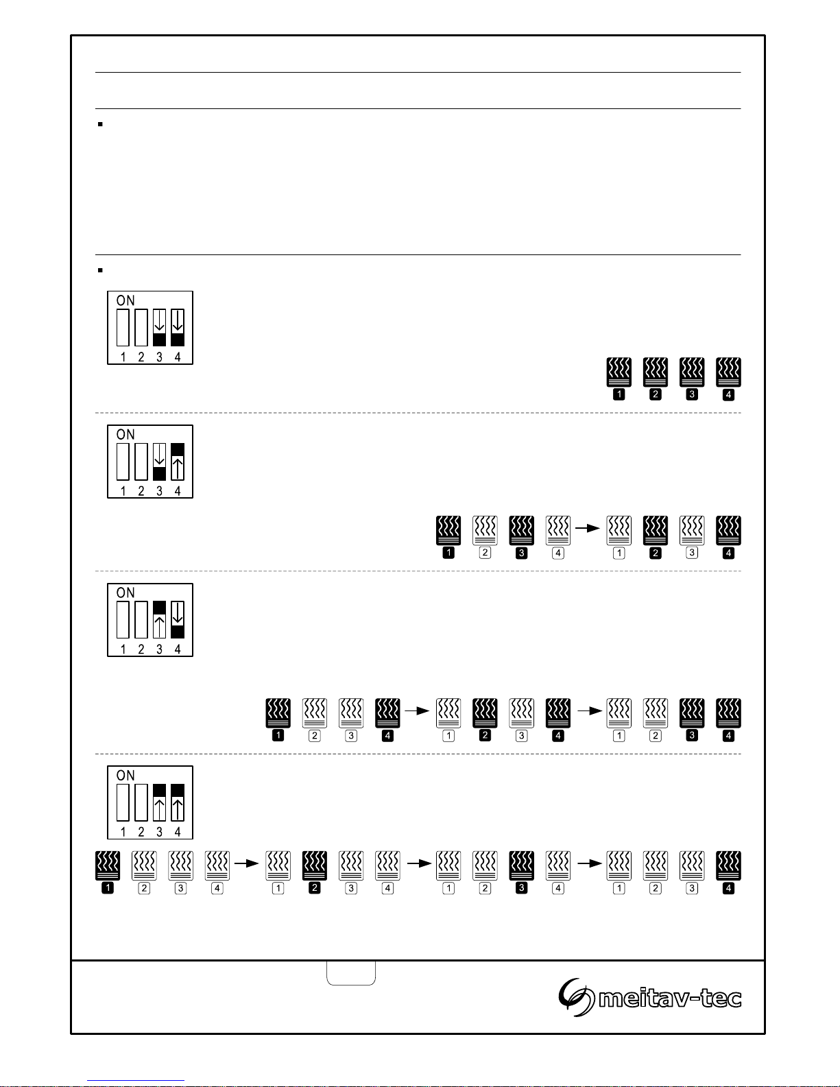
DIP switches S3 and S4 – heaters sequencing logic
Use DIP switches S3 and S4 to define the sequencing logic of the heater (zones) as follows:
S3 OFF, S4 OFF
All 4 outputs work per request from the temperature sensor
S3 OFF, S4 ON
Outputs 1+3 and outputs 2+4 work together (according to splitting time)
S3 ON, S4 OFF
Outputs 1,2 and 3 work in sequence (according to splitting time) and output 4
works continuously.
S3 ON, S4 ON
All 4 outputs work in sequence (according to splitting time)
Note: if output 5 is set to work together with outputs 1-4, (see “Heater output no. 5 logic” in the technician
settings), it will operate the same as output 4.
Page 15
Technician settings (Cont’)
Tel: (856) 2882882
Tel: +972-3-9626462
Fax: +972-3-9626620
PYROBOX3/3C/5
-TRACE
Owner’s manual & Technician Settings
Pg. 15
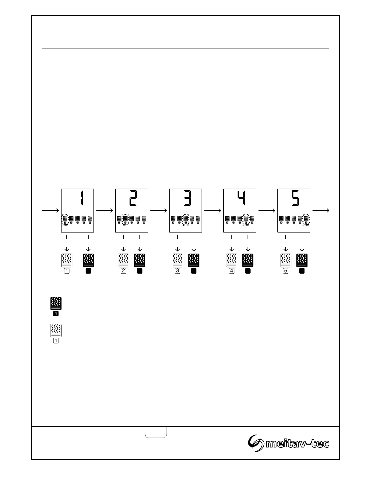
Follow the steps below to enable or disable each of the 5 zones.
By default, all zones are enabled.
1. Turn the thermostat OFF.
2. Press and hold both the [+] and the [-] buttons simultaneously for 10 seconds.
3. Choose the required zone using the [Select] button. Selected zone number will appear on display
and the heater icon will flash.
4. Use the [+] button to enable the selected zone (black heater icon).
5. Use the [-] button to disable the selected zone (white heater icon).
6. Repeat steps above 3 to 5 for any required zone.
7. Press and hold both the [+] and the [-] buttons simultaneously again for 5 seconds to return to
normal display.
Enable/Disable zones
[+] & [-]
(10 sec.) [Select] [Select] [Select]
54321
[-] [+] [-] [+] [-] [+] [-] [+] [-] [+]
[Select]
[+] & [-]
(5 sec.)
Black icon – Zone enabled
White icon – Zone disabled
Page 16
System Errors
Tel: (856) 2882882
Tel: +972-3-9626462
Fax: +972-3-9626620
PYROBOX3/3C/5
-TRACE
Owner’s manual & Technician Settings
Pg. 16
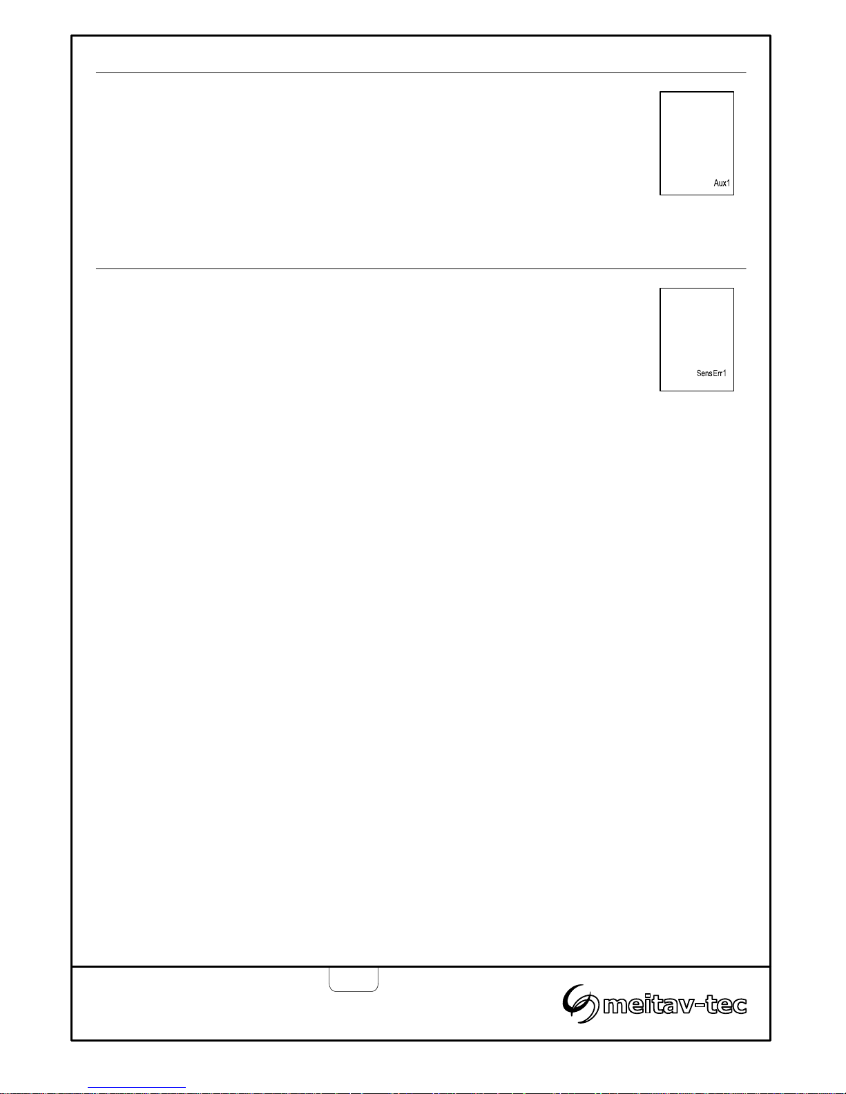
Temperature
Sensor error
Error 2 – Temperature sensor is not connected or short circuit
“SensErr 1” Will appear on display.
Communication
error
Error 1 – MODBUS Communication error
“SensErr 1” Will appear on display.
Page 17
Appendix 1
Calibrating and testing the internal GFCI
Tel: (856) 2882882
Tel: +972-3-9626462
Fax: +972-3-9626620
PYROBOX3/3C/5
-TRACE
Owner’s manual & Technician Settings
Pg. 17
12
NO
NC COM
SUPPLY
10
20
30
40
50
100
90
80
70
60
CURRENT TRIP
% FULL SCALE
TIME
DELAY
MIN MAX
Turn clockwise to increase
Counter-clockwise to decrease
(Default: Minimal time delay)
“ON” Time delay
10
20
30
40
50
60
70
80
90
100
Current Trip - % full scale
(model dependent – see table)
(Default: 20%)
Indicator (%)
Current trip (Amps)
0.1
0.2
0.3
0.4
0.5
0.6
0.7
0.8
0.9
1.0
Tripped relay LED indicator
TRIPPED
Remote C.T.
PYROBOX3/3C
0.01
0.02
0.03
0.04
0.05
0.06
0.07
0.08
0.09
0.10
PYROBOX5
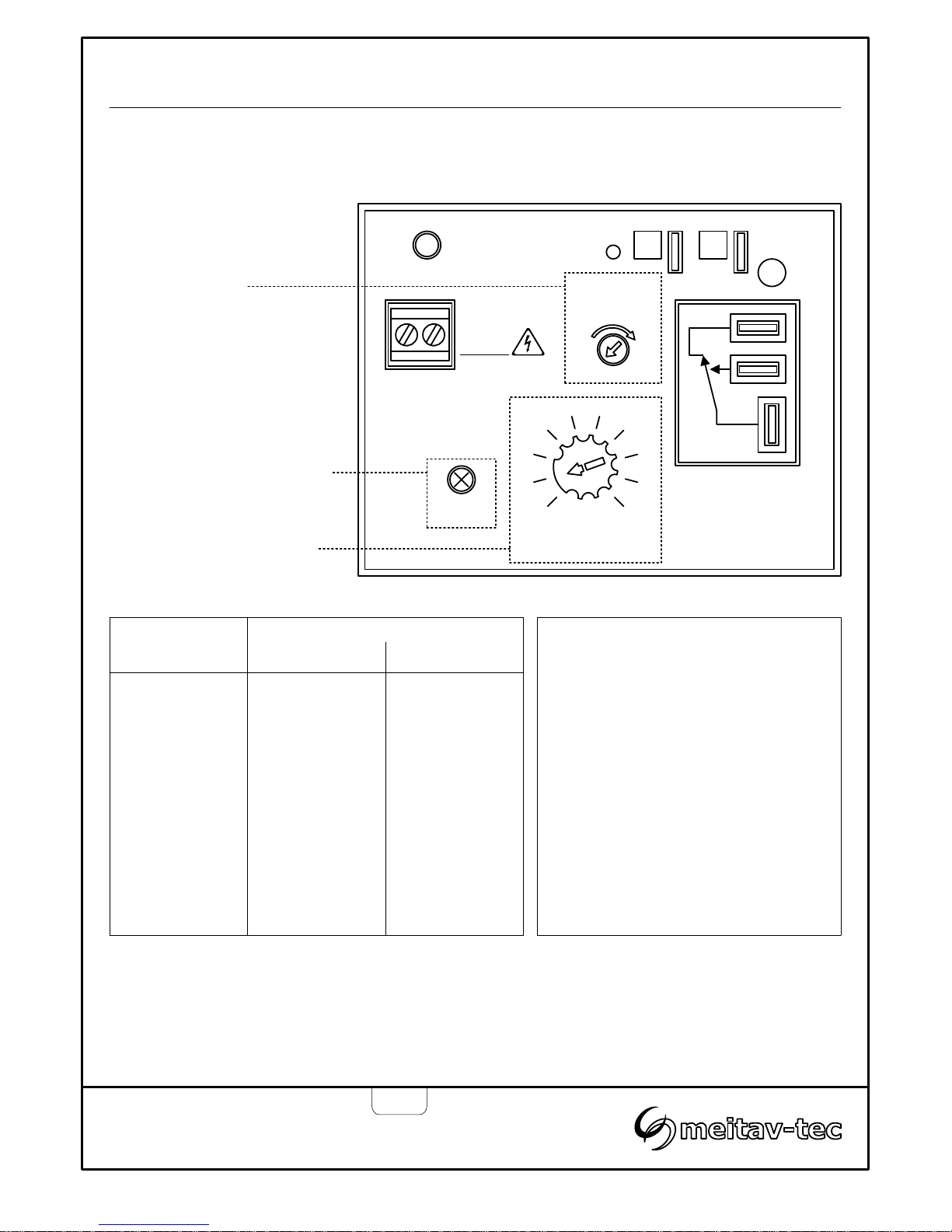
The GFCI (ground fault circuit interrupter) is designed to provide protection for electrical equipment.
The “ON” Time Delay and Current Trip should be configured to match application requirements.
DANGER
HIGH VOLTAGE
GROUND
FAULT
SENSOR
GFCI TEST
The GFCI should be tested monthly.
Press the red GFCI TEST button
located next to the R,C terminals
inside the box for 3 seconds to trip the
outlet and break the circuit. The RED
internal LED on the GFCI and the
RED external lamp on the box door
should lit. Press the RESET GFCI
button on the box door for 5 seconds
to return to normal operation and
reestablish power and protection.
Page 18

Notes
Tel: (856) 2882882
Tel: +972-3-9626462
Fax: +972-3-9626620
PYROBOX3/3C/5
-TRACE
Owner’s manual & Technician Settings
Page 19

Notes
Tel: (856) 2882882
Tel: +972-3-9626462
Fax: +972-3-9626620
PYROBOX3/3C/5
-TRACE
Owner’s manual & Technician Settings
Page 20

 Loading...