

Page 1
102” REPUBLIC P-47 THUNDERBOLT
BUILD INSTRUCTIONS
.
(COPYRIGHT PROTECTED 2014)
ALL RIGHTS RESERVED
Page 2

BEFORE YOUR START
The fuselage self-jigging system used allows easy accurate assembly. But, attention to
detail when cutting the parts from your patterns is very important.
SUGGESTIONS FOR PARTS ACCURACY
1. Cut the patterns to within 1/4” of the outside lines.
2. Attach to the selected wood with scotch tape.
3. Use a #11 blade to punch through the patterns. Every few inches, place scotch
tape over the cut area. When done, you still have the patterns to verify your
finished parts. If you acquire a desk style scotch tape dispenser it will be a great
asset now and in the future.
4. Alternate methods used are of carbon paper over the wood, or “SEE TEMP” to
make separate patterns while preserving the originals.
5. After cutting out the bulkheads, make a 1/4” x 3/8” x 1” piece of balsa to be used
as a depth gauge. Check all notches in the bulkheads for proper depth. (Same for
wing rib notches.)
REMOVAL, ASSEMBLY AND INSTALLING THE WHITE PLASTIC PARTS
1. A small pair of tin snips is an excellent choice for accurate and easy cutting along
the separation lines. A razor saw is good for straight cuts.
2. When ready to install the several plastic parts to the fuselage, tape the parts in
place. Use thick C.A. to glue. DO NOT use kicker as it will attack the plastic.
BELIEVE!
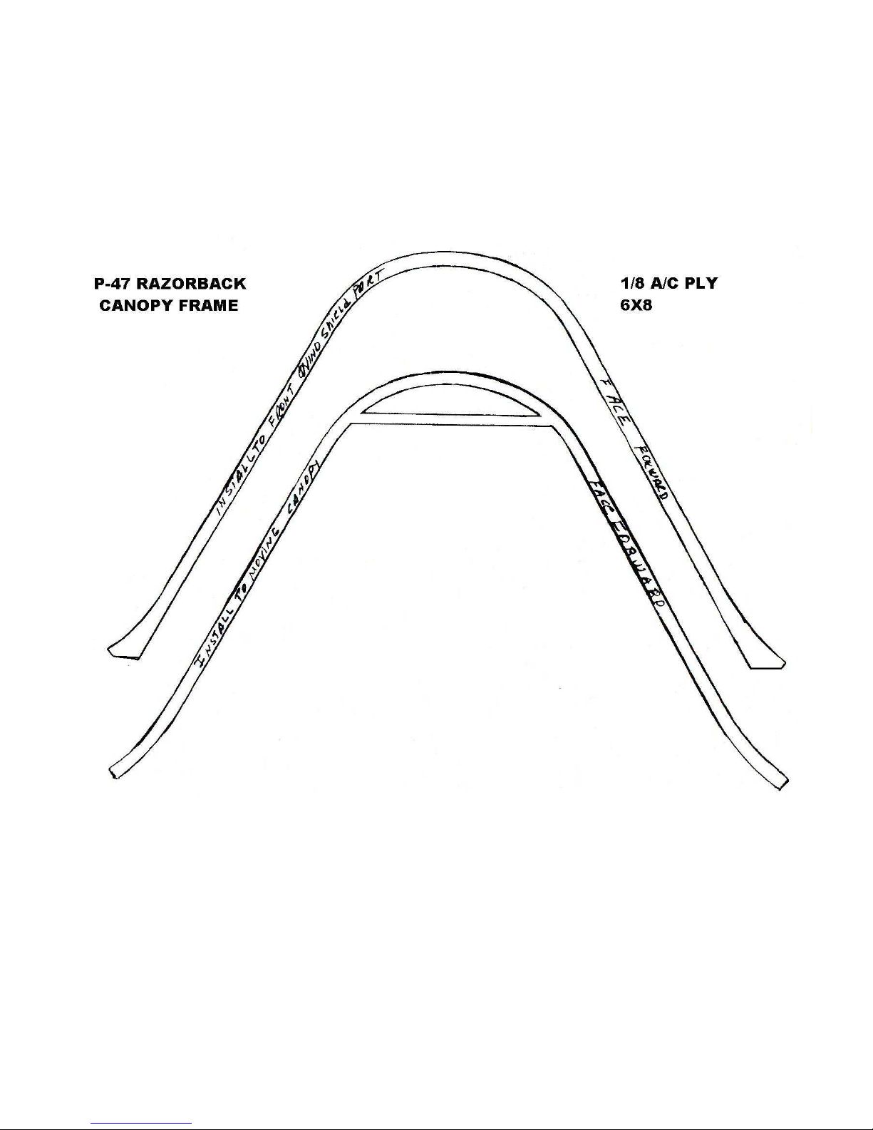
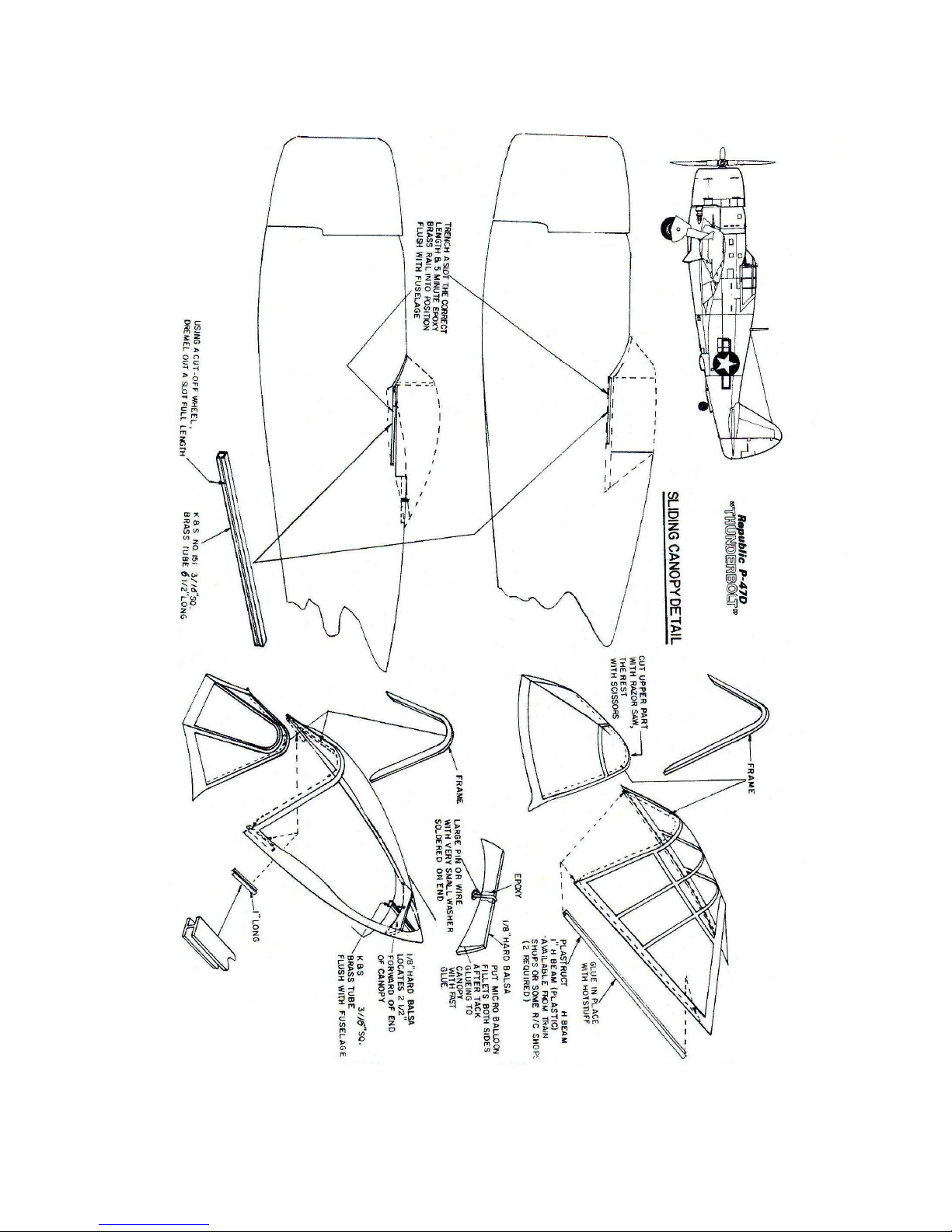
CANOPY
1. When canopy has been fitted and exactly in place on the fuselage, install some
pins next to the front windshield, along the bottom of the sides and at the rear to
facilitate exact location when gluing the canopy down. Note: Recommend fiveminute epoxy or R/C 56 glues. Do Not Use C.A.
Page 3

WING INSTRUCTIONS
Note: This wing design has a flat bottom, thus no need for jigs, etc. However, you will
need a flat surface to build your wing. If you don’t have a suitable surface, find an
inexpensive hollow door from your local Home Depot or building supply store. Use a
level to insure no twist exists.
1. After all ribs have been cut out, do yourself a favor. Check all spar notches for
exact depth and width NOW! Make up the “spar brace” now. It should be just
under 3/4” wide. Make from basswood or equivalent. Write left and right on
each end.
Note: The 3/8” x 3/4” spar material must all be of the same width (3/4”) in order
for the shear webs to fit flush to the bottom, mid and upper spars. Check this
now.
2. Make up the main rear spars now. There are 2 lefts and 2 rights, so go slow. The
1/4” x 3/8” spars install to the bottom of the wing (see rib notches).
Note: This wing is framed directly on the plans without any sheet. The wing
sheet panels are shown with dotted lines and are made up after complete wing
framing is complete. The flaps (optional) and ailerons are fabricated away from
the main wing plans.
3. Epoxy the W-5A and W-7A doublers to the W-5 and W-7 ribs. Remember to
make up two lefts and two rights as the “A’s” face each other. Important!
4. Pin in place the main and secondary spars. Also the flap FH-1 and aileron AH-1
headers.
5. Install all ribs now. Be sure that they all touch the work surface. Adjust notches
as needed.
6. Loosely install the top spars. Use a 48” straight edge to check that the spars are
seated into the notches and have no high spots. Adjust as needed. Do not glue
yet.
7. Install the single piece 3/32” balsa shear web’s to center of both bottom spars
between ribs W-7 and W-12.
8. Put in place the two top spars. Check for high spots. Trim the shear webs as
needed. With the spars straight glue in place.
9. Install front and rear vertical grain 3/32” shear webbing to the secondary spar.
10. Install the 3/32” vertical grain shear webbing to the front only of the main spar
W-1 thru W-7.
Page 4

WING SEPARATION FEATURE
11. Place your “Spar Brace” in place against the bottom spar. Wedge in place. Be
sure the centerline on your “Spar Brace” is lined up with W-1. (Note: If you want
a one piece wing, glue the “spar brace” to the bottom spar.)
12. Cut the mid spar pieces 3/8” x 3/4” stock to 3-7/8” long. Place against the top of
“Spar Brace” and against the front shear web. Apply a small amount of thick
C.A. to each end where it touches theW-5 and W-6 ribs. When set remove the
“Spar Brace” to insure that the glue did not contact the “Brace.”
13. Reinstall spar brace and repeat above until all mid spar pieces are in place. Note:
The piece between W-1 and W-2 has to be shaped in order to fit in place.
14. Remove spar brace. Thoroughly glue (C.A.) all mid spar pieces to the front web
and ribs.
15. Now install the shear webs to the back of the main spar. Use thick C.A. and not
so much that it runs inside of cavity.
16. Watch for glue running into “Spar Brace” cavity. Remove any globs.
17. Install the spar brace and check fit. It must enter to a depth of the centerline. Did
you put the proper left-right side into the wing when doing the mid spar
assembly? If not, change the designation (reverse the left right).
18. Install the “G.P.” (Gear Plate) and two “G.B.” (Gear Blocks) to W-5, 6, & 7.
Install 1/4” thick by 3/8” balsa to top and bottom of “G.P.” at W-5 & 7.
19. Install the “Wing Tongue” to front of W-1-2. Use 30 Minute Epoxy.
20. Pin the 1/8” L.E.-2 to front of ribs with the top edge even with the top front of the
ribs. Use your straight edge to check for ribs that are too long. Trim. Glue in
place. Sand to an angle that part of L.E.-2, which flows into rib contour.
21. Install the W.P.B. 1/8” ply part between W-1 and W-2 behind the flap header.
Install the 1/8” balsa F.H.-2 to F.H.-1. This part ends flush with top of ribs (see
plans).
22. Your retracts should be installed now if you are going to use bolts and blind nuts.
If you plan on using sheet metal screws you may proceed. The flap actuators are
also installed NOW!
23. Make up 4 “A”-“B” wing sheet parts. Glue the “B”s to the “A”s. (You will have
to add on a 1”extension to the “A” and “C” sheets.) (Do this to the tip end.)
Page 5

24. Make up 4 “D” and “E” sheets. Glue together. The “E” sheet is cut to size of “E”
template shown.
25. The top and bottom “C” sheets are now installed. The front of these panels
centers on to the secondary spar (front). Note: When cutting the edges so that
they are straight, be sure the width of “C” sheet is 3 15/16” wide when done.
26. The “D”-“E” panel is trimmed so that the rear edge centers onto the 1/4” x 1/4”
spar before gluing in place. The “H” panel (3/32” bal with 1/32” ply laminate)
butts to the rear of “D”-“E” panel. See side view of flap detail and detail shown
on right wing plan.
27. Make up “E” panel and sand angle to it as shown on side view of flap. Lay aside.
28. For proper flap fit to the wing it is important that the rear edge of the “E” sheet
centers on the 1/4” x 1/4” spar. Doing so properly positions the “H” panel in
relation to flap.
Note: Do not install the “D”-“E” sheets until flap actuation system is decided on.
We only show the system we think is most appropriate. You may actuate the flap
in same fashion as ailerons if you like.
29. Proceed to build ailerons and flaps. Suggest that you install flap hinges (Dubro
#257 suggested) before installing the “H” panel to wing.
Note: The flap activators shown will work with standard 70 oz. servos. However,
180° proportional servos would be a better choice. In order for the aileron to
operate freely when the flaps are down, you will have to angle sand the end of the
aileron. This will not be noticed from above.
30. See plans instructions for aileron and flap building instructions.
HORIZONTAL STAB INSTRUCTIONS
1. Draw a straight line on your workbench 36” long. Center both S-9’s onto this
line. Glue the S-10 onto the S-9’s. Pin the assembly to your work surface in a
convenient place to work.
2. Be sure you have the 90° braces on hand. Glue the two W-1’s together. Put rib
location marks onto the S-8’s and S-9’s NOW.
3. Pin the W-1s in place (onto the S-10). Install the 90° brace in place – glue base to
S-10.
4. In order to use a square to align the W-1’s you will need two pieces of 1/8” balsa
under one end of the square to level it with the top of S-10. A centerline on the
W-1’s helps with alignment.
Page 6

5. Repeat step 3 and 4 to install S-6. Be sure you install the hinge blocks now.
6. Install S-8’s.
7. Install all ribs now. Be sure that they are not over length, as they will cause a bow
in the S-8’s (use a straight edge along S-8 at this time).
8. Important: Install the inboard hinge blocks NOW! Don’t forget!!
9. Sand an angle to top and bottom of S-8’s to match the flow of the ribs. Same for
S-9’s.
10. Make up 4 “A” “B” 1/8” balsa panels. Join the “B”s to “A”s and the scrap parts
to the “B” parts. These panels should be 1/8” larger than the frame.
11. Trial fit the panels to stab frame. Trim inboard edge so that it centers on the W-
1’s.
12. In order to avoid warping of the stab frame, it is advisable to install the top and
bottom panels at the same time. Do this as follows.
A. Pin both panels to S-8 being sure that they center on W-1s and overhang
the S-8 by 1/16”. Now glue to S-8.
B. Apply white glue to all ribs.
C. Pull both panels down onto frame and C.A. rear edges to the S-9.
D. Sand the panels flush with the S-8 and S-9.
E. Install the 3/8” x 1/2” leading edge. Shape.
F. Install S-7 tips. Do not shape these yet.
G. Reinforce the center section with 1” wide reinforcing tape and thick C.A.
or your choice of glues. IMPORTANT!
ELEVATOR INSTRUCTIONS
1. Using template supplied make up 4 1/16” balsa “E”-9 elevator parts.
2. Lay one onto the plans and pencil mark rib locations onto the “E”-9. Do the same
onto the right side “E”-9.
3. Glue the “E”-8 in place being sure it is 90° to “E”-9. You might use the hinge
blocks to assure this. Be sure the 1/8” x 1” ply control horn plate is in place.
Page 7

4. Install all ribs.
5. Use a large sanding block to angle sand from the “E”-8 to the trailing edge of the
“E”-9. See cross section of elevator. If you want a scale like edge at the trailing
edge you should sand the E-9 down to about 1/32” thick or less.
6. Angle sand the top “E”-9 at its trailing edge. Same as bottom “E”-9. Cut away
that portion that overhangs the E-1.
7. Note: When top E-9 is in place the trailing edge will be slightly forward of the
bottom “E”-9 edge. This allows easy C.A. application in this area.
8. When top “E”-9 is in proper position apply C.A. to trailing edge area between
“E”-2 and “E”-4.
9. You can pry the “E”-9 away from the frame in order to apply white glue to ribs
and the rest of frame. Use masking tape to hold down while glue dries.
10. Install “E”-6 tip blocks. Sand close.
11. Hinge elevator to stab.
12. Apply masking tape to both sides of hinged area to hold elevator straight. Now
sand the stab and elevator tips to shape.
VERTICAL FIN AND RUDDER
1. The vertical fin assembles the same way as the stab.
A. Pin the F-2 to work surface.
B. Install the two 90° braces next to proper rib locations.
C. Install F-4 & F-8 ribs – be sure they are 90° both ways.
D. Install balance of ribs. Do not force them, as they will cause F-1 to distort.
E. From the supplied templates make up the fin sheet from fin sheet 1, 2 and
3 templates.
F. These fin sheet parts must install flush to top of F-8 and F-2. The lower
edges will eventually be trimmed to fit the top of the horizontal stab.
Page 8

RUDDER
Note: All control surfaces on the full scale had their trailing edges end in a thickness of
1/16”. In order to duplicate this, a bit of patience is needed in properly sanding to the
correct angle the two cover sheets and the center R-3. Study the cross section before
proceeding. Decide now if you want to hinge in scale fashion.
A. Make the R-3 and R-1 parts. Both should be as hard as you have on hand.
Should be “C” grain.
B. To locate the R-1 onto the R-3, position the 3/8” x 3/4” x 16” block “A” to
front of R-3 then place the R-1 next to the block “A.” Glue R-1 only.
Remove the Block “A” – One side only.
C. Make up ribs from scrap 1/8” balsa. Glue in place one side only.
D. Put masking tape over the top edge of the R-1 to protect it from sanding
the ribs.
E. Use a 2” x 6” block sander to shape the ribs and trailing edge of the R-3.
F. Install the 1” balsa hinge block NOW!
G. Install the 1/16” sheet to the rudder. Trim.
H. Install the R-2 block “A.” Sand flush with sheet.
I. Turn over and repeat above.
UNDER BELLY (U.B.)
This assembly is designed to be removable for easy access to the hold down bolts. You
may choose to make a one piece wing and glue the under belly to the wing which will
require access holes to the wing bolts. We advise that you make the U.B. removable.
1. Assemble the U.B.2A, U.B.-2, 3, 4 and 5.
2. Install the wing and bolts. Tighten.
3. Test fit the U.B. assembly to the wing and fuse. Trim the U.B.2A as necessary.
4. Put wax paper between the ends of U.B.2A and fuse bulkheads F-2 and F-4C.
Install the assembly with pins.
5. Install the U.B.P. 6’s. The two layers of soft 1/16” will make this part easy.
Same for the U.B.P. 7’s. Use wood glue to install the top U.B.P. 6 & 7’s.
Page 9

6. Remove the U.B. and install the U.B.P.-8’s.
7. Install the 1/4” x 1/2” x 2” A/C ply part (for front U.B. hold down) to the F-2 into
the opening called for on F-2 template.
8. Install the 1/8” x 1” x 3” A/C ply part to wing with 1/4” overhanging center of
wing. (This allows rear U.B. screw attachment.)
9. Install the 1/16” ply inlays at screw head locations. Drill and counter sink for
screw heads (1 - #8 x 1-1/2” wood screw and 1 - #8 x 2-1/2”).
10. Install assembly using the wood screws. Check for clearance where the U.B.P.-8
nears the wing. You should have a small gap. Install 1/4” x 1/4” stringer to
inside of U.B.P.-8 just above its edge to strengthen the area.
11. Suggest you use “Bondo” putty (available auto supply stores and elsewhere) to
make a perfect fit of the U.B. to the wing. Lay saran wrap on wing. Use tape to
hold flat.
12. Mask the area to avoid a mess. You should have a small spatula to apply and
shape your fillet. Do not create a thin edge when shaping.
FUSELAGE
The fuselage builds onto a simple crutch in the bubble canopy version. The “razor back”
version is achieved with the option formed fiberglass part available at a nominal charge.
1. The crutch drawing is supplied on the plans in two parts. Be sure to use a four
foot straight edge when taping the two drawings together.
2. Make up the fuselage side parts FS-1 and FS-1A. Use a straight edge along the
“Top” edge of these parts to insure an exact straight edge. Note: This edge glues
to the crutch and makes the crutch straight. See next step. Use 1/64” ply to
double the FS-1. See plans. It must be able to bend to conform to bulkhead
curvature.
3. The method of aligning the crutch when installing the FS-1 and 1A side parts is
very simple. Make a line down the sides of the crutch on its center. The crutch
material is 3/8” x 3/8” so the line should be 3/16” from the top or bottom of the
crutch sides. Install pins on this line at each cross piece location.
4. The top of the crutch is the side without the triangle braces. Turn over so these
triangle pieces face up. Set the sides (F.S.-1 and 1A) against the pins with the tail
ends of the sides even with F-10. Tack glue both sides at F-10 area. Be sure the
sides are down against the pins, slowly glue both sides simultaneously to the
crutch going forward from F-10. Go Slow
!
Page 10

5. A simple method to keep the crutch from twisting follows.
A. Install F-2 and F-8 to crutch. Make up 90° triangles from scrap to insure
these bulkheads are glued at 90° to crutch. Very Important.
B. Make up two supports from 1/8” x 7” x 12” pieces of light ply. Tack glue
to front of F-2 and F-8 up against the fuselage sides.
C. The supports align the crutch to your workbench.
D. Put the fuselage on the bench in a comfortable place to assemble. Mark
the bench where the supports touch. This allows accurate placement when
returning the model to the bench.
E. In order to check the crutch for alignment, lay an 18” long straight
anything across the crutch at F-1 and F-8. Sight these two straights from
either end of fuselage. If needed install shims to adjust the support.
Recheck alignment.
6. Tacks glue the rest of the bulkheads in place (except F-1 & F-8A). F-9A is now
installed between the F-9 & F-10. Sand the exposed edge to angle – see F-9.
7. Install the top center 1/4” x 38” stringer between F-4 and F-9 (do not glue yet).
The F-8 should be at 90° to the crutch. Measure the distance between F-8 and F-9
at the crutch level. Glue the stringer to F-8. Measure between the F-8 and F-9.
Distance should be the same as the crutch level. Adjust and glue stringer to top F-
9. Repeat this through F-4. Install F-1 firewall now. Be positive you have it at
90° to the crutch. Make 90° triangles to assure this. Install F-3 now.
Note: F-8A is installed after retract T.W. is installed to it. You may install F-8A
any time before the bottom side stringers are installed. However, before
continuing, the tiller arm and 1/8” wire part that holds the wheel must be removed
so that the retract can be retracted up into the fuselage because the rest of the
lower fuse parts are installed over the retract. Then the T.W. door material is
laminated (3 layers of 1/64” ply with a thin layer of white glue applied to both
sides of center layer) and then taped to the door area of the fuse. This creates
curve shaped doors. Then door template is then placed on the curved door
material and the doors are then cut out. Neat, eh?
8. The F-123 part when installed to top of F-1, F-2 and F-3 might require trimming
of the notches to allow the F-2 & F-3 to remain at 90° to crutch. Install the two F123-A and F-123-B parts now, to the first notches above crutch in bulkheads F-1,
F-2 and F-3.
9. Install the two stringers just below the crutch. Use clothespins to clamp the
bottom of FS-1 and 1 fuselage sides to the stringers. Do both sides at the same
time to avoid distortion of crutch. Check crutch alignment again. If O.K., glue
the sides to the stringers.
Page 11

STOP HERE: Because of the interesting features presented in this design you
must take time here and now to decide on which features you want to incorporate
into your project. We hope you decide on all of them. The following will
describe the methods and reasons for prescribed steps for the several optional
features.
10. After the controls are all installed along with the doors, install all top stringers.
Keep checking crutch alignment as you go and install to both sides at same time
to help avoid distortion. Put all stringer extension splices to rear between F7 and
F8. The 48” pieces install forward area.
Latent Note: If you do not install the “Air Vane” part when doing the intercooler
doors, you can remove the doors (which helps avoid damage) until later in the
program. Make a screwdriver access hole directly above the pivot/screw (in the
FS-4A plank) for reinstallation later on.
11. Install balance bottom stringers. Note: These stringers should extend forward
from F-5 by 2-1/8” (they are trimmed later on).
12. Install FS-3A plank. Be sure it fits flush with back of F-10.
13. Install a 1/64” x 2” x 1” splice doubler to FS-3A before installing the FS-3. Be
sure the 1/64th splice doubler wood grain runs forward (not up and down). Same
for all splices.
14. Install intercooler doors now! If you are building the razor back you may elect to
leave a hole in the top plank to facilitate “door” pivot screw removal. Removing
the door until construction is complete is a very desirable feature. The 1/32” ply
part “air vane” can be installed after final door installation.
15. Install the rest of the top planks FS-4, 4A and FS-5.
16. The F.S.-2 installs next. Because there is no stringer to glue to, F.S.-2 must be
edge glued to the bottom edge of F-1. Be sure it fits to the wing saddle shape of
F.S.-1. Suggest you tape the F.S.-2 part in place and then glue it.
17. Install the F.S.-2A now being sure it fits flush to back of F-9. Trim at splice if
necessary. Install F.S.-2B. It must fit curvature of the airfoil shape of F.S.-1. Do
not fit any of the F.S. parts flush to F-1. They all will hang over a bit. Sand flush
to F-1 after installation.
Install wing saddle doublers NOW. (Suggest you put many holes into the wing
saddle doublers inn order to more easily apply thin C.A. to the areas.)
18. Install wing hold down 1/2” x 1” x 6” hardwood blocks.
19. Locate the F-4C lower bulkhead and the F-4D part, which locates the F-4C part to
its proper location and angle. Install.
Page 12

20. Install the F.S.-2B bottom planks and the balsa blocks F-9 B & c to F9A. Shape.
Note: Put the T.W. door part in exact position. Draw a line around the doors. Cut
away the wood to this line. Now your T.W. is accessible.
21. Make up the 1/32” ply wing fillet part.
22. Install the wing to the fuse being sure to measure from a point on the wing back to
the F-10. Drill through the hole in the wing (1/4” x 20” x 2” bolt hole) into the
1/2” x 1” x 6”. Hold down block. Remove wing and check to see if the dimple is
on center of the block. If so, change drill bit to a 13/64” bit then finish drilling
through. Now tap a 1/4” x 20” thread through the blocks.
23. Make up many triangle braces from 1/8” balsa that is installed to top of 1/32” ply
fillet part and against fuse side. These act to hold the 1/32” ply down against the
wing.
24. Mix up a batch of micro balloons and polyester resin putty. Fill fillet area. Sand
to shape.
25. If the front of the wing appears to be a bit loose, add a piece of 1/64” ply to the
bottom of the tongues to shim the wing upwards.
26. Now that the wing is installed, you can install the horizontal stab, as you need the
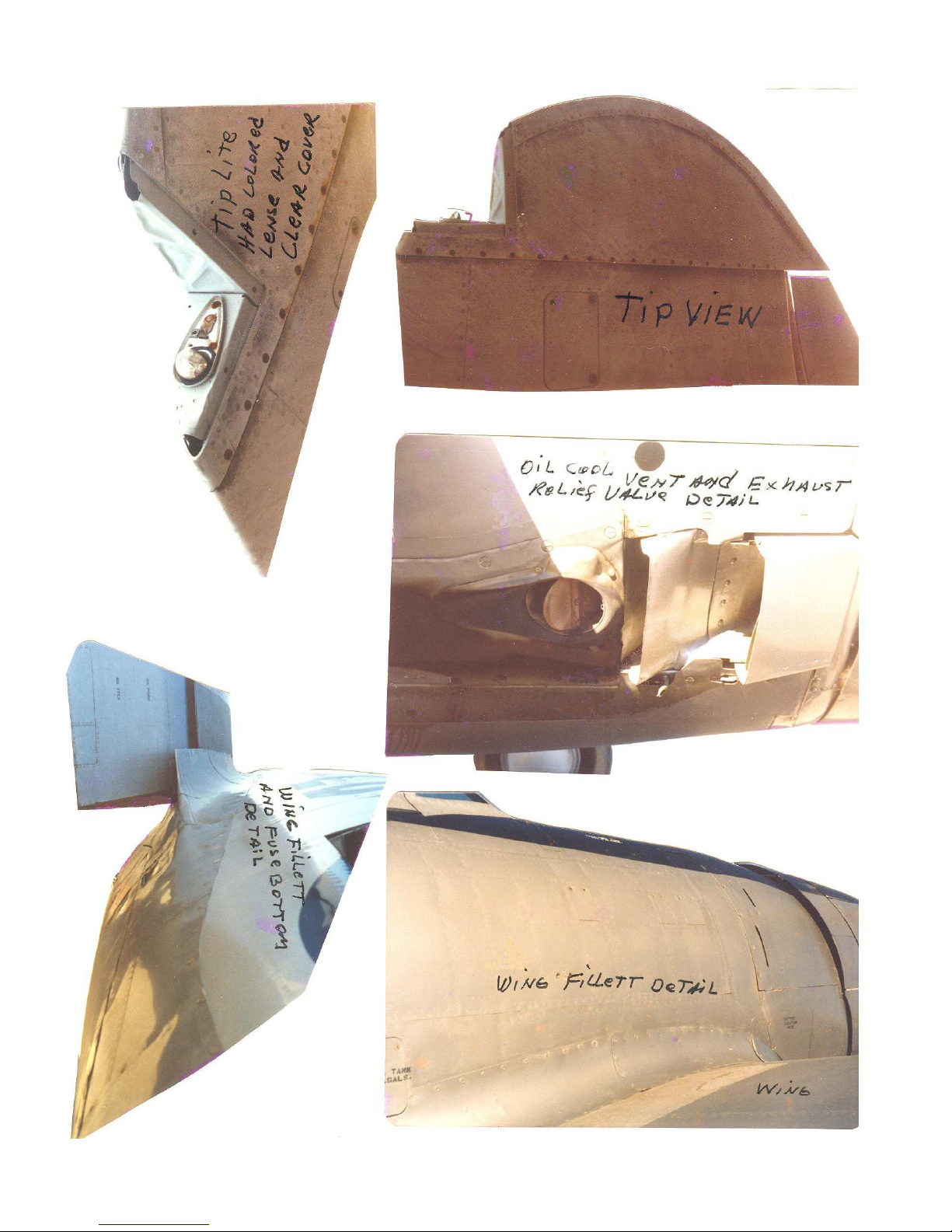
wing for stab alignment. The vertical stab follows. See pictures on plans for
shape of area between fin and stab. Use soft blocks.
When the Supercharger compresses the air, the air gets too hot for proper use by the
engine, thus a method to cool this air is used. Compare the hot compressed air to the
water in your car engine. As you know, the hot water is fed through your radiator in
which cool air is pulled around the many tubes that hot water circulates through. Now,
imagine the hot air being drawn and pushed through these same many tubes with cool air
being forced around these same tubes. This is what intercoolers are, radiators that cool
hot air – not water.
If you want to install moving intercooler doors (neat idea), it is a very simple matter
because all of the figuring has been done. All you have to do is cut out the various wood
parts per the several templates. Assemble as shown and install with one pivot screw per
door. Flex Cables Sullivan #508 (2 regular) are hooked up to the throttle servo or an aux
channel for movement.
Even the routing of the cable housing is plotted for you. YOU MUST DO THIS NOW!!!
Important Note: The reason we recommend and show the use of Nyrod type controls is
because they are very easy to route through the fuselage. They are also very reliable and
simple to hook up. Depending on whether you choose the removable cockpit floor and
moveable intercooler doors determines the need to route all of these controls (8 so far) as
Page 13

shown. If you are on top of such matters, you of course can do your own thing. For
those of you who have better things to do than engineer a new “mouse trap” be assured
that all control systems shown are simple to install and very reliable. Amen!
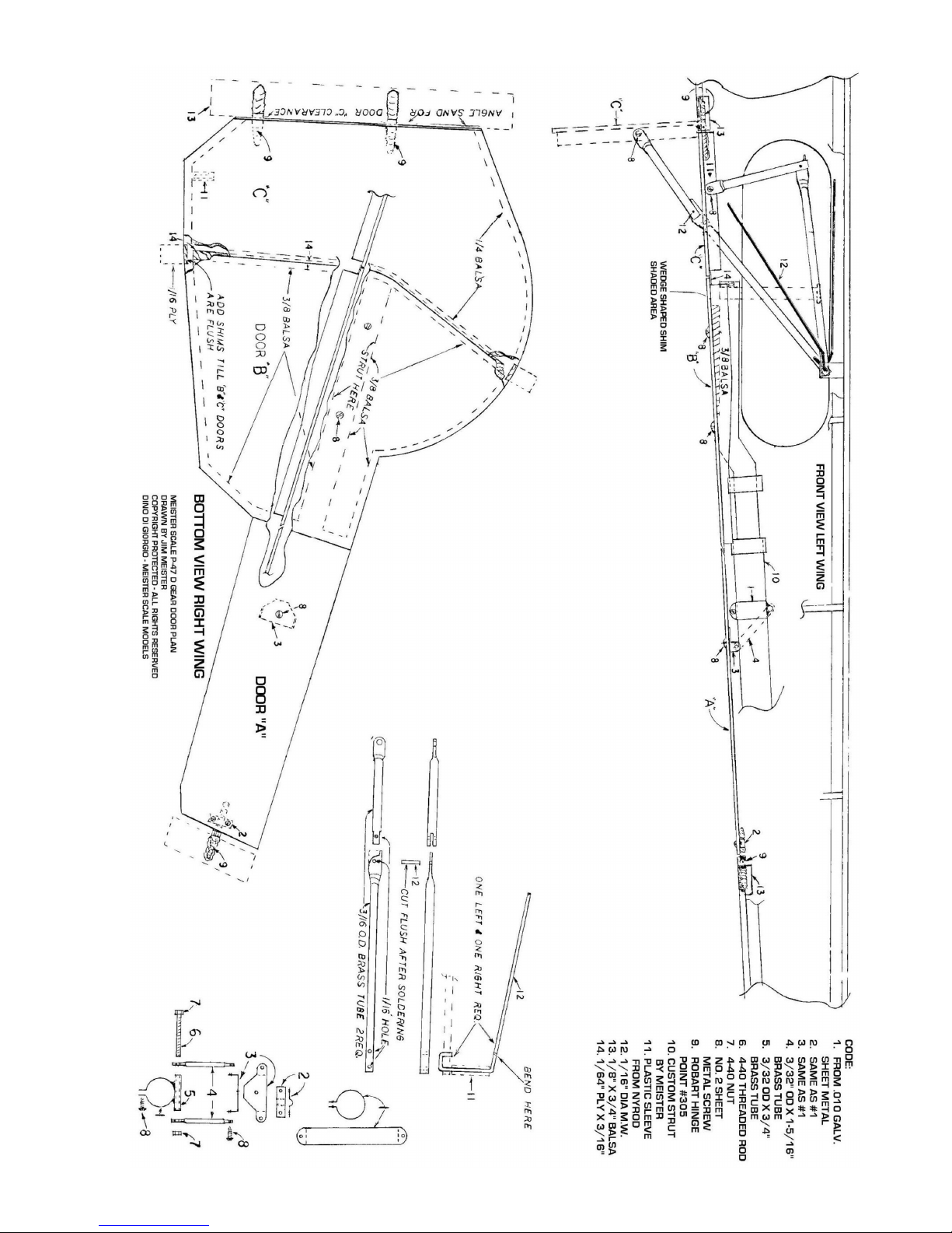
A. Retracts – Main. We offer custom struts for the P-47 and economical retractors
for this model (see www.meister-scale.com or our latest catalog for info). The
installation is made easy due to the prearranged mounting platform installation. If
this is your first time at retracts please do not hesitate to go for it. They are very
easy on this model.
If you opt not to install retracts you can install gear grooved blocks just like in
your smaller models. Use a main block and then a shorter one just behind the leg
(about 5”) to support the backward movement of the leg. Solder the support to
the leg using small diameter copper wire. (About 4” down the leg from the wing.)
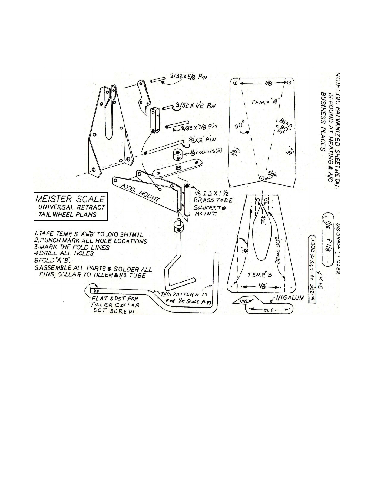
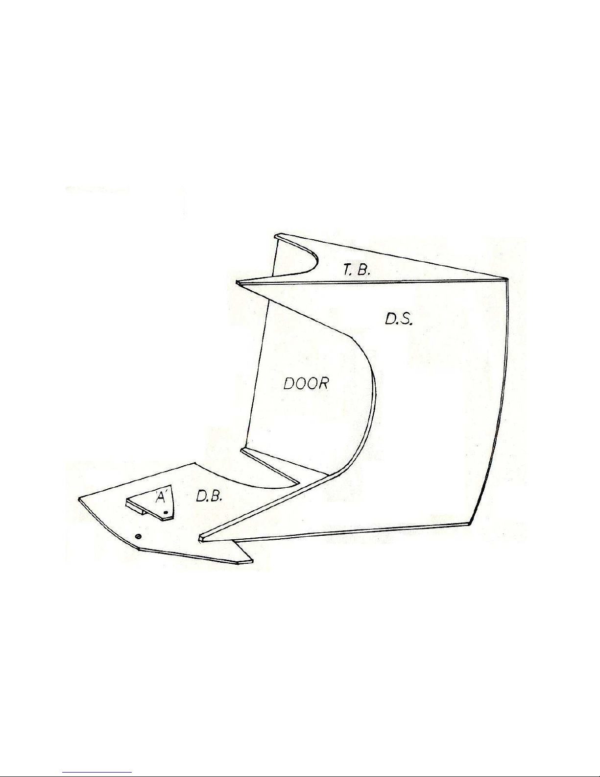
B. Tail Wheel Retracting. It is a very simple job to make up your own retracting
T.W. using the supplied plans and templates. Most heating and air conditioning
contractors will have the .010 galvanized sheet metal you will need. The square
brass tube is K & S which all hobby stores have. You can make this retract in less
than three hours. Your alternative is to purchase a Robart Manufacturing or
similar retract which will fit nicely in the fuse. This item is in stock and we can
ship on receipt of your order either by mail or by phone with your charge card. In
any event, you need it now in order to continue with the fuselage.
Note: The T.W. location shown on the side view on plans is in the exact scale
location.
Very Important: The retract T.W. must be installed to the F8A bulkhead before
the bulkhead is installed to the crutch.
C. Intercooler Air Exit Doors. For your enlightenment the plans illustrate several
drawings showings some of the many fascinating inside systems of the P-47.
Page 14

FLYING
The P-47 has the same “Fun Scale” characteristics as its predecessors. Very slow take off
and landing capabilities so do not use much throttle on first take offs, if you want realism.
The P-47 is very acrobatic if set up for it, so help yourself.
CONTROL THROW SET UP
1. Ailerons 1” up and 1”down.
2. Elevators 1” up and 1” down.
3. Rudder 2” each way.
4. Throttle must be set to a low idle to allow the model to fly slowly enough to land.
Note: The above can be changed to individual taste after initial flights.
Page 15
Page 16
Page 17
Page 18
Page 19
Page 20
MEISTER SCALE FUSE SIDE DOOR
Page 21
Page 22
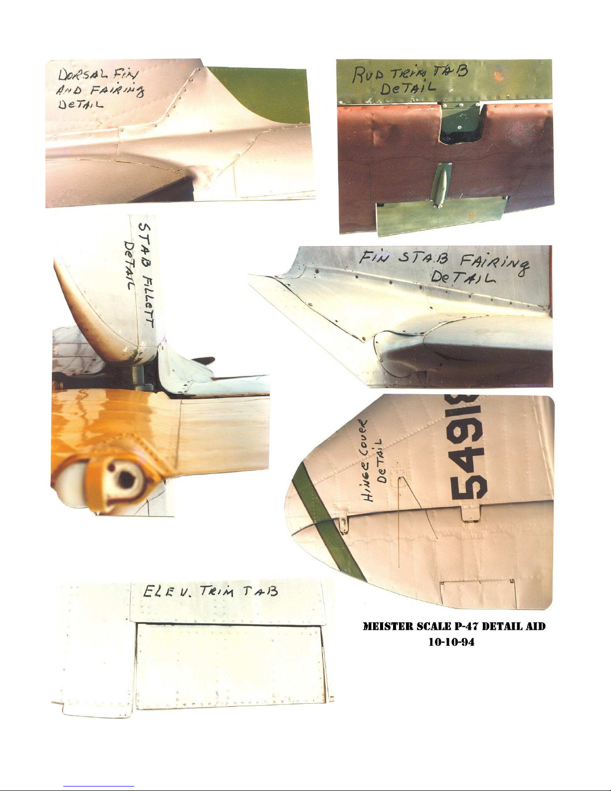
Page 23
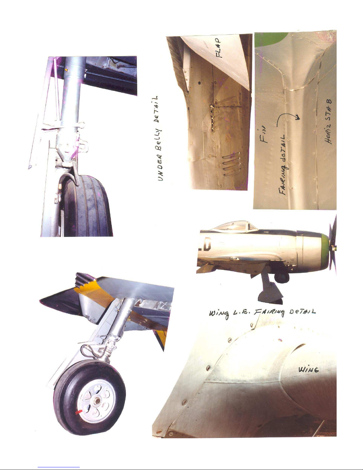
Page 24
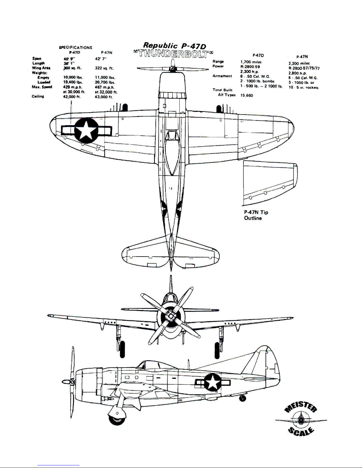
Page 25
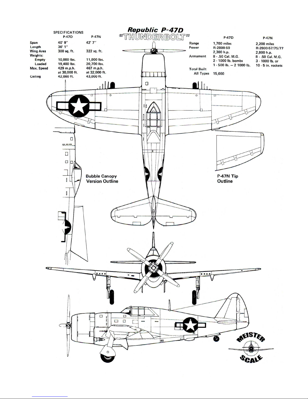
Page 26

FUSE LIST (BALSA)
1 - 1/16” x 3” x 36” Hard HRS, HRP, ARMOR PLATE
4 - 1/16” x 3” x 36” Soft UBP Planks 6, 7, 8
10 - 1/8” x 3” x 36” Med All non-ply bulkheads F9A, F9B, RB1, FS
Parts, UB2A, BF4, HR
4 - 1/8” x 4” x 36” F8, FS-2C, FS-5, FS-5A
30 - 1/4” x 3/8” x 36” Med Stringers
1 - 1/4” x 3” x 36” Med F123, F123A & B
6 - 3/8” x 3/8” x 36” Med Crutch
1 - 1/2” x 3” x 36” Med F9C, F9D
FUSE LIST (HARDWOOD)
Note: All parts marked 1/8 ply may be made of light ply.
3 - 1/64” x 6” x 12” Ply TW Doors & Seat Back
1 - 1/32” x 6” x 12” AC Door base, Air Vein, Top Brace
1- 1/8” x 12” x 48” Ply F2, F3, F4, F4D, F8A & B, F10, DS-Dash,
Seat Base Support & Cockpit Floor
1 - 1/4” x 12” x 36” AC F1 & Wing Tongue Doubler, Cowl Plate
2- 1/2” x 1” x 8” Bass Wing Hold Down Blocks
1 - 1/2” x 1-9/16” x 24” Pine Cowl Spacer Blocks
HORIZONTAL STAB
3 - 1/8” x 3” 36” Hard S-1 Thru 6, S-8, 9 & 10
E-1 Thru 5, E-8 & Stab Sheet
1- 3/8” x 1/2” x 18” Med Hinge Block
1 - 3/8” x 3/4” x 36” Med Stab Leading Edge
ELEVATORS
1 - 1/16” x 4” x 36” Hard E-9
1 - 1/2” x 3/4” x 36” Med Hinge Blocks
1 - 1/2” x 3” x 6” Med E-6
1 - 1/2” x 1” x 6” Hard E-10
Page 27

WING
4 - 1/16” x 4” x 36” Hard Ailerons
3 - 3/32” x 2” x 24” Med “H” and FT-2
4 - 3/32” x 4” x 36” Hard AIL Webbing
2 - 1/8” x 3/8” x 36” Hard Spar Extensions
10 - 1/8” x 3” x 36” Sheet “E”, FB1 & 2
FX, FH-2, F-G, F-T and GT
Ribs W-1 Thru W-4, W-8 Thru W-14
LE-2 Flap & Ailerons-Ribs
2 - 1/8” x 3” x 48” Sheet “B”
12 - 1/8” x 4” x 48” Sheet “A”, “C”, & “D”
2 - 1/4” x 1/4” x 36” Med Top of Ribs W-2 Thru W-8
2 - 1/4” x 3/8” x 36” Med Bottom Spar Extensions
6 - 1/4” x 1/2” x 36” Med Secondary Spars
7 - 3/8” x 3/4” x 36” Bass Main Spars AH-1 & AH-2
2 - 1/2” x 1/2” x 36” Med FH-1
2 - 1/2” x 1-1/2” x 48” Med LE-1
2 - 1” x 1-1/2” x 36” Soft FP-1
1 - 1-1/2” x 3” x 18” Soft Tip
1 - 1/32” x 6” x 24” Ply Flap Top Sheet Part FT, “H” & Wing Fillets
1 - 1/16” x 12” x 24” Ply Gear Doors
1 - 1/8” x 6” x 24” Ply W-5 & W-7
1 - 1/8” AC Ply Wing Bolt Plate, W-5A, W-7A, Servo Rails
1 - 1/4” x 6” x 24” AC Ply Wing Tongue Gear Plate & Flap Servo Rails
4 - 1/2” x 1/2” x 6” Pine Gear Plate Reinforcement
1 - 3/4” x 2” x 36” Bass Spar Brace & Wing hold Down Blocks
 Loading...