

Page 1
B MONITOR 0001 02-15 E M
Operating Instructions for analog transmitter MONITOR
Operating Instructions for analog transmitter MONITOR
-1--4-
2 Safety guidelines
1 Introduction .......................................... 1
2 Safety guidelines ................................. 1
3 Functional description .......................... 1
4 Installation ............................................ 1
5 Device description ................................ 2
6 Programming ........................................ 2
7 Connection diagram and dimensions ... 2
8 Technical specifications ........................ 3
The analog transmitter MONITOR is characterized by
reliable function and simple operation. In order to use
the advantages of this equipment in its entirety, please
consider the following:
Each person assigned to work on or operate this
equipment, must have read and understand the
Operating Instructions and in particular, the safety
references!
2.1 General information
To ensure safe operation, the device must be operated
only in accordance with the instructions in this manual.
Additionally, use of the device requires adherence to
all accident prevention-, legal regulations and safety
standards for the respective application.
2.2 Correct use in accordance
with these instructions
The analog transmitter MONITOR must only be used in
combination with the following flow monitoring- and flow
indicating devices from Meister Strömungstechnik:
DUM
DWM
RVM/U-1
RVM/U-2
RVM/U-4
DKM-1
DKM-2
DKME
DWM-L
RVM/U-L1
RVM/U-L2
RVM/U-L4
Any additional or different application, above and
beyond the correct use described in these instructions,
is deemed as incorrect use.
3 Functional description
The analog transmitter MONITOR detects the position
of magnetic floats or pistons with the aid of Hall-sensors. An analog signal, appropriate to the position, is
provicled.
4 Installation
The analog transmitter MONITOR and the appropriate
flow sensor come pre-assembled. For installation into
the pipe system, please refer to the Operating Instructions for the flow sensor.
Content
1 Introduction
Meister Strömungstechnik GmbH Tel. +49 6096 9720-0 info@meister-flow.com
Im Gewerbegebiet 2 Fax +49 6096 9720-30 http://www.meister-flow.com
DE-63831 Wiesen All rights reserved
2.3 Qualified personnel
Flow monitoring/metering devices equipped with the
analog transmitter MONITOR must only be installed by
qualified personnel, who are able to correctly employ
the device for its intended purpose. Qualified personnel
are persons who are familiar with the setup, assembly,
start-up, and correct use of these devices, and who
are able to independently carry out the work assigned
to them.
Meister Strömungstechnik GmbH Tel. +49 6096 9720-0 info@meister-flow.com
Im Gewerbegebiet 2 Fax +49 6096 9720-30 http://www.meister-flow.com
DE-63831 Wiesen All rights reserved
Page 2
B MONITOR 0001 02-15 E M
Operating Instructions for analog transmitter MONITOR
Operating Instructions for analog transmitter MONITOR
-2- -3-
The device has a short-circuit proof and reverse
polarity protected switching output (Push-Pull). Analog
output 4...20 mA or 0…10 V is offered concurrently.
Programming is done with a magnetic clip through the
IP 67 enclosure. The MONITOR-electronics linearize
and convert the primary signal into a conventional
4…20 mA or 0…10 V output signal while providing
a flexible switch at the same time. Linearization and
calibration are done automatically.
5 Device description
Meister Strömungstechnik GmbH Tel. +49 6096 9720-0 info@meister-flow.com
Im Gewerbegebiet 2 Fax +49 6096 9720-30 http://www.meister-flow.com
DE-63831 Wiesen
All rights reserved
Meister Strömungstechnik GmbH Tel. +49 6096 9720-0 info@meister-flow.com
Im Gewerbegebiet 2 Fax +49 6096 9720-30 http://www.meister-flow.com
DE-63831 Wiesen
All rights reserved
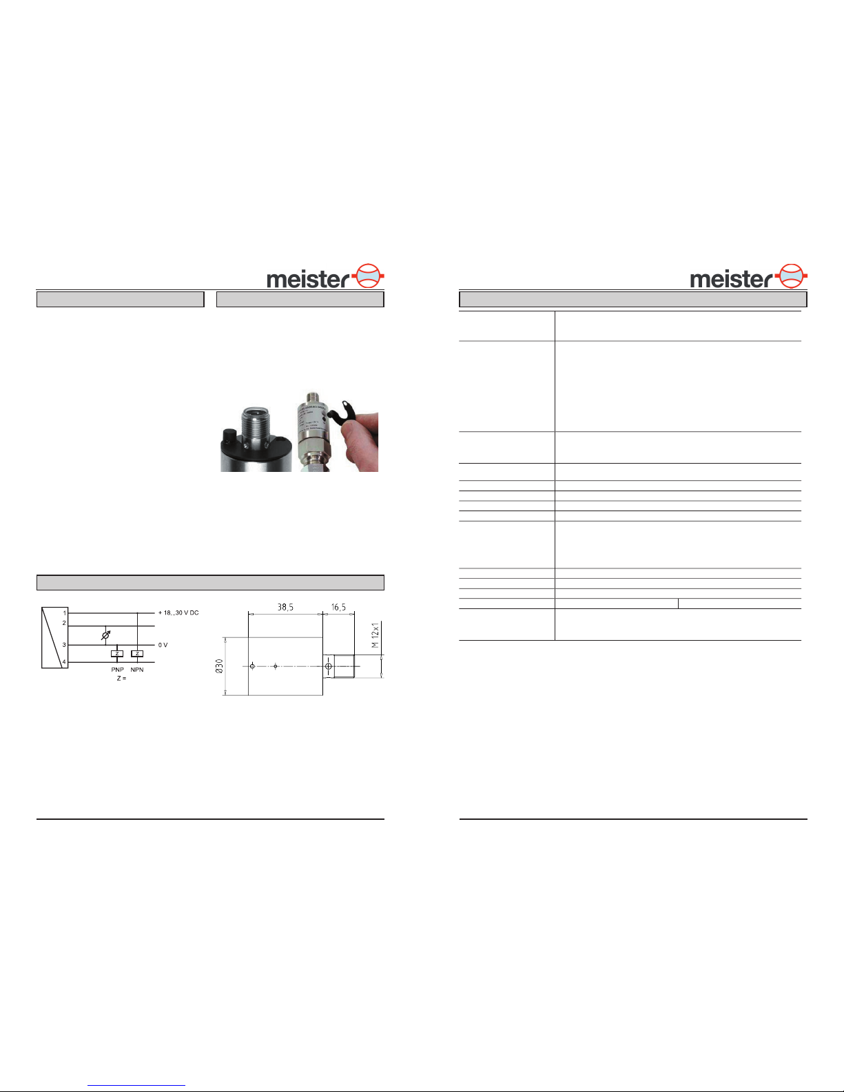
6 Programming
The calibration magnet, clipped into a groove on the
device, is used to program the switch point. After
calibration, the magnet may be returned to its grooved
seat or stored elsewhere, to protect the data entered.
The calibration point is marked on the label.
7 Connection diagram and dimensions
Fig. 1: Switch point teach-in
Fig. 2: Connection diagram Fig. 3: Dimensions
8 Technical specifications
Analog output
4...20 mA or 0...10 V (Please specify when ordering!)
Current output
max. load 500 Ω
Voltage output
max. current 10 mA
Switch output
1 short-circuit proof and reverse-polarity protected switch output
Alarm: low / cable break low / OK: high
Push-Pull output
The output is self-configuring and can be connected as PNP- or NPN-switch. The switch
contact is available as Min- or Max-contact. (Please specify when ordering!)
Load
max. 100 mA
Hysteresis (electronic)
2% full scale.
The position of the hysteresis is dependent on whether the contact is programmed as a
Min- or Max-contact.
Contact programmed as Min-switch: above Max-switch: below
Hysteresis (mechanical)
Depending on the sensor employed
LED
LED – switch status (yellow) in the plug connector outlet
On: switch output OK
Off: Alarm
Flashing: teaching/programming of the switch point
Switch point programming
“Teach-in” of the switch point with the calibration magnet
(see Section 6, „Programming“)
Operating voltage
24 V (18...30 V)
Power consumption
< 1 W
Connection
for plug M12x1, 4 pin
Ingress protection
IP 67
Accuracy
DUM, DWM, RVM/U-1, RVM/U-2 and RVM/U-4 ± 3 % of full scale deflection
DKM-1, DKM-2 and DKME ± 5 % of full scale deflection
(with calibration at a specified viscosity)
DKM-1, DKM-2 and DKME ± 10 % of full scale deflection (viscosity compensated)
DWM-L, RVM/U-L1, RVM/U-L2 and RVM/U-L4 ± 10 % of full scale deflection
Repeatability
1 % of full scale deflection
Operating temperature
- 20 °C ... + 70 °C
Storage temperature
- 20 °C ... + 80 °C
Materials
Housing
stainless steel 1.4305
Note
The sensor is configured to customer specifications. It is thus ready for immediate use
without programming! Please note that the MONITOR-electronics is calibrated to the flow
sensor and can not be replaced without recalibration! Refer also to the data sheets and
operating instructions of the respective flow sensor.
brown
white
blue
black
Load
brown
Analog output
Switch output
 Loading...