

Page 1
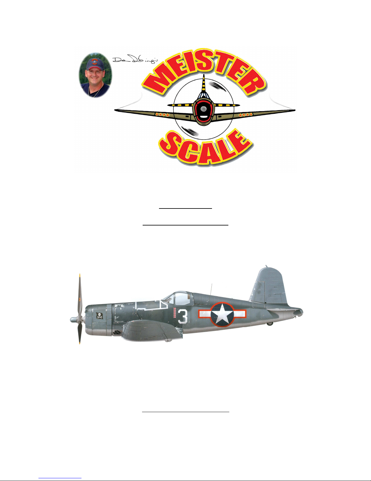
100” WING SPAN
F4-U CORSAIR
(COPYRIGHT PROTECTED 2014)
ALL RIGHTS RESERVED
Page 2

INVENTORY SHEET
FUSELAGE WOOD
Balsa
20 – 1/8” x 3” x 36” Assorted Med-Soft
4 – 1/8” x 4” x 36” Med F.S.-1 & 2
1 – 1/4” x 1/4” x 36” Med
10 – 1/4” x 3/8” x 36” Med
5 – 3/8” x 3/8” x 36” Med Crutch
1 – 1/2” x 3” x 36” Soft Block “A” R-6A
1 – 3/4” x 3” x 36” Soft Nose Radius Blocks
1 – 1” x 3” x 36” Soft F-11A
Hardwood
1/8” Door Skin or Luan Mahogany wall paneling or Lite Ply. Door Skins (when
available) are 36” x 80” and of course the wall panel is 48” x 96”. Even though you only
need ten square feet for fuselage and wing, the excess is handy for future needs. Lite Ply
is not nearly as strong as the above, but is available though Hobby Sources in exact
quantity needed.
1 – 3/4” x 1” x 12” Pine Wing Hold Block
1 – 1/2” x 1/2” x 24” Pine Servo Rails
STAB WOOD
Balsa
2 – 1/8” x 4” x 36” Med-Soft E-1’s
1 – 1/4” x 1/2” x 36” Med-Soft Elevator Ribs
1 – 1/4” x 3/4” x 12” Med-Soft Rudder Ribs
1 – 1/2” x 1” x 18” Soft R-4
2 – 3/4” x 1” x 36” Soft E-2’s, E-3’s, E-4’s
S-3’s, S-4’s, S-6
3 – 3/4” x 1” x 36” Soft R-1, R-2, R-5, R-6
F-1, F-,S-2, S-5, S-7
1 – 3/4” x 1” x 36” Rigid S-1
Summary
1 – 1/8” x 4” x 36” Med
2 – 1/4” x 5/8” x 24” Med
3 – 1/4” x 3/4” x 36” Med
1 – 1/2” x 1/2” x 12” Med
1 – 1/2” x 1” x 10” Med
1 – 5/8” x 3/4” x 26” Med
4 – 3/4” x 1” x 36” Med
Page 3

WING WOOD
Balsa
4 – 1/16” 3” x 36” Gull Section Sheathing
4 – 1/8” x 3” x 36” Wing Sheet, Ribs &Cap Strips
4 – 1/8” x 4” x 36” Wing Sheet, Ribs & Shear Webb
4 – 1/8” x 1/2” x 36” Spars Outboard Wings
4 – 3/8” x 1” x 36” Ail.-1 & Ail.-2
2 – 1/2” x 2” x 36” L.E.-1A
1 – 1/2” x 3” x 36” L.E.-1
Hardwood
2 – 1/4” x 6” x 7” Aircraft Ply (Optional Retract Platform)
1 – 3/4” x 3/4” x 48” Pine Wing Bolt Blocks & Fixed Gear Blocks
1 – 1/4” x 12” x 40” Aircraft Plywood
BUILDING NOTE:
Please keep in mind if you are using a Robart or Sierra retracts, you will need to modify
the wing and fuse location to accommodate the retracts.
Page 4

FUSELAGE INSTRUCTIONS
1. Cut out all fuselage parts from indicated material. Be sure you have the 3/4” x 1”
x 12” pine parts on hand. Note: The holes for routing the plastic control rods are
shown on the bulkhead templates. Decide if you want to use this system.
2. Build the “Crutch.”
3. Join the F.S.-1’s and F.S.-2’s and the F.S.-3’s and F.S.-4’s aligning the edges as
shown on side view. Suggest you lay the parts to show a “left” and a “right” side.
This will give you a smooth outside surface to the fuselage.
4. Install pins to side of “crutch” at each bulkhead station. This pin location should
be on center of the 3/8” square crutch side.
5. Clamp the fuselage sides to the “crutch” against the pins. The front end of the
sides should be flush with the front end of the “crutch.” Glue.
6. Install the F-1 and F-7 to the “crutch” using temporary 90° supports to insure 90°
alignments to the “crutch.”
7. In order to build the fuselage free of a twist, try this.
A. Cut two pieces of D.S. to 5-1/2” x 10-1/2”.
B. Spot glue to F-1 and F-7 up against the “crutch.” (Either side of the
bulkheads.)
C. Find a convenient area on your work bench for easy access to the fuselage.
(If you have an Island Work Bench, you are lucky.)
D. Mark around the 5-1/2” x 10-1/2” supports with a pen or pencil onto the
work surface. (This will allow exact placement of the assembly after
removal for other steps.)
E. Pick out two 36” sticks that are straight. Lay them across the “crutch” at
F-1 and F-7.
F. Stand at one end of the fuselage and determine if the sticks are parallel.
Shim the work bench leg required to bring the sticks parallel.
8. Before installing the rest of the bulkhead, do this: using a piece of scrap 1/4” x
3/8” balsa, check the width and depth of the many notches in the bulkheads. The
1/4” x 1/4” notches ditto.
9. Loosely install F-8 holding in place with a rubber band. Install the F-2 through F-
6 bulkheads being sure they are 90° to “crutch (F-1A and F-3C are installed later).
Be sure to install the 3/4” x 1” x12” pine wing hold down part now.
Page 5

10. Fit and install the F-11 to the top of F-4 to F-8.
11. Install all 1/4” x 3/8” stringers above the “crutch.” See note at F-8 ref. stringer
attachment to F-8.
12. Wet the fuselage sides. Use large rubber bands tied together and held with large
pins to gently pull the sides in. Let dry before gluing.
13. Install the F.S.-5 to the F.S.-3-4 panels.
14. Install the F.S.-3-4-5 panels.
15. If the wood of the cockpit sides is weak, consider installing a 1/8” balsa doubler
to each inside.
16. Install nose plank (F-1 to F-4).
17. Plan and install your elevator rudder, retract tail wheel and steering tail wheel
controls now. In the prototype we used DuBro “Lazer Rods” for the two elevator
controls and one each for the rudder and retract tail wheel. U control cable was
routed from the rudder servo to the retract tiller arm through small diameter
plastic tubing. The small plastic of the “lazer rods” works fine.
18. Remove the support from F-7. Install F-1A and F-3C to the Crutch (90°).
19. Install all lower 1/4” x 3/8” stringers and F-8. Install the 1/4” x 1/4” stringers
between F-7 and F-8. (Have you installed flight controls yet?)
20. Join the F.S.-1A’s and F.S.-1B’s again using a straight edge. Install. Use wetting
method if necessary – do not overly force the bending. Install the F.S.-1C’s.
Finish the bottom planks at your leisure.
21. Install the wing saddle doublers (4 pieces). Note: Check the wing saddle area for
excess bulge out.
22. Install F-10 & F-9 after the retract tail wheel assembly is installed.
OR
23. Make up fixed tail wheel wire per pattern and install to F-8. Use plastic 1/8” gear
clips (hump) to locate the wire.
24. You may enclose the areas behind F-7. Suggest two layers of 1/16” soft balsa
between F-7 and F-9 for easy forming.
25. Install the 2-3/4” x 3” x 10”. Nose radius blocks now.
Page 6

Special Note: Do not install fin until wing is installed. This allows proper
horizontal stab. Alignment and then proper fin alignment. (90° to horizontal
stab.)
OUTBOARD PANELS
1. Make 4 each of the front sheet A-B and 4 each of the rear sheet C-D. Lay all
bottom sheets and cap strips onto plans.
2. Locate the WST part (Wing Servo Template) and make the 1/8” x 1” x 4-1/8” ply
servo rails and install to plans.
3. The construction is basic, except for the plug-in feature. Before installing the
“wing plug” perform the following:
A. Fit the “wing plug” to the gull section so that there is no slope.
B. Drill the 1/8” hole for retainer pin.
C. Install the W-3 rib onto the “wing plug.” Note: If the rib matches the
adjacent rib. Trim as needed.
D. Notice that the rib tends to pull away from gull rib. Glue a 90° balsa
support to the “wing plug” and the rib to keep the rib flush to its mate. Do
this to the front and rear of the W-3 ribs.
E. Now install this assembly to the plan and proceed with outboard wing
panel.
4. When paneling is finished, install to gull. You will need to sand the joining area
to allow the plug to insert all the way. Some fiddling will be required here.
5. Access to the retaining pin is through the wheel wells. If you use fixed gear make
an access hatch in bottom of the wing.
Note: The tip end of the bottom sheet “C” is cut at W-10 and bent upwards to join
the top sheet C.
WING INSTRUCTIONS
The wing is very simple to build IF you follow the following suggestions.
1. Make up the main and secondary spars.
Page 7

2. Make a master W-2 rib from 1/8” ply and use to trace all W-1 and W-2 ribs to
guarantee all ribs are the same at the slots and outer edges. Go slow here.
3. Make measuring gauges from balsa to check all notch widths and depths in
the ribs and the main spar and secondary spar. Very Important!
4. Mark the main spar with “FRONT”. Now mark the “RIGHT” & “LEFT” on
the front side of the spar. Trial fit your wing plug parts to the main spar. Mark
this right or left depending on the best fit. Sand the wing plugs so that they fit
without play up or down.
5. Install the M.S.D. and W.P.D. to the main spar. Be sure to clean glue from the
cavity so that the wing plug fits smooth. See notes on plans-Wing Plug
Retaining Pin. Do this now if you have decided to make the outboard panels
removable. The 1/8” pin is accessible through the wheel well. Make a springloaded device to hold the pin in place when the model is being flown. Should
you use a fixed gear, make a hatch in the bottom of the wing for access.
6. Because the center section (gull) of the wing is built away from the plans,
reference lines must drawn on the flat work surface. Draw a line 28” long
parallel to and 12” from the front of the workbench. At each end of the 18”
line draw at 90 degrees to it a line 10” long in each direction. Your layout
should look like an “H” when assembling the ribs to the spars. It will provide
a reference to keep the assembly in square. The main spar sits upright over the
28” line. Simple install all ribs to the slots. Check to be sure that the bottom of
all ribs reaches the bottom of both spars and not beyond. When all is aligned,
apply your choice of glue. **See note on Main Spar Template about 1/8” x
1/8” balsa strips to keep rib square to the spar line. VERY IMPORTANT: Be
sure the LEFT & RIGHT panels are removed BEFORE gluing the ribs to the
spars!!
7. Install fixed gear blocks now.
8. Install the 1/8” x 3” x 9” wing sheet between W-1 and the doubler W-2. Also
the 1/8” x 3” x 3” sheets to W-2 – W-3. The sheets only join one of the
doubled W-2’s. See front view of the wing. Start at the rear and work forward.
Leave out the last piece of sheeting near the leading edge until later
9. Install retracts and airlines now.
10. The gull section is sheeted with two layers of 1/16” balsa ½” wide where the
airfoil is curved to 3” wide where flat. Stagger the second layer over the first
so that the joints miss each other. Use CA for an easy effort.
11. Bolt a ¾” x ¾” x 2” pine block to the center of both spars. Drill a ¼” hole
vertically on the center of the block.
Page 8

12. Place wing in fuselage. Line up and drill 7/32” pilot holes into the ¾” x 1” x
12” pine wing hold block. Tap with ¼” x 20 tap. You will need a ¼ x 20 x 2”
and one ¼ x 20 x 3” bolt.
13. If your wing saddle does not fit the wing good enough try these steps:
A. Cut a piece of 80 grit sandpaper to a 2” width by 8” long.
B. With the wing loosely screwed to the fuse and right side up, lift the fuse
away from the wing. Slide the sandpaper grit up between the wing and
saddle.
C. Gently push down on the fuse and then pull the sandpaper out.
D. Repeat until fit is correct.
14. The tail feathers are installed now. Install wing for visual alignment reference.
TAIL FEATHERS
Before ordering your wood, make note of the density recommended on the various parts.
Your goal is light, but very stiff balsa.
Check for a straight piece for the S-1. Decide if you will use two servos to drive the
elevators or one servo. Make up wire to connect the elevators if you choose one servo.
Note: Do not install fin or stab until wing is installed for alignment reasons.
COWL INSTRUCTIONS
1. The cowl plate installed 1-1/2” into the cowl. Put many marks 1-1/2” in around
the inside of cowl (soft lead pencil).
2. Mark the top of cowl plate at its center, same for cowl.
3. Install plate to proper depth. If loose, install shims to hold plate in cowl. Tack
glue plate to cowl. (Cowl is of A.S.S. plastic.)
4. With engine installed, install cowl. Check prop thrust washer with center of cowl.
You may have to relocate the cowl plate a little.
5. Finish gluing the plate with C.A.
6. Apply a large fillet of “BONDO” or micro balloons – resin mix all around plate
both sides.
7. Two ounces glass cloth and resin both sides of the plate will provide an excellent
adhesion.
Page 9

BALANCE NOTES
Back in the mid 1990’s with a Zenoah G-62 installed, D & R retracts, retract T.W., seven
servos, 800 M.A. Battery pack and Monocote covering, the Corsair weighed in at 23lbs.
Remember, that was back in the mid 90’s using outdated material.
The Servos were installed between F-1A and F-2. The balance with gear up was a bit on
the nose heavy side. The engine with “Slim Line” muffler weighed around six pounds.
You can determine where you should place your radio in the model by using the above
information. Remember: If you use paint on your model, plan on moving everything
forward.
If you install a 1/8” sheet floor onto the crutch between F-3 and F-4, it makes a nice
platform to support the fuel tank and air tank.
GENERAL INSTRUCTIONS
ENGINE
Recommended engines are 1.2 cu. In. to 5 cu. In. The wing separation feature should not
be used when engines in excess of 3 cu. In. are used. Use your own judgement.
COWL
As shown a 1/4” ply cowl plate is installed where the cowl flaps start. Use micro
balloons or baking soda and C.A. to make a fillet on each side of plate glass this area with
2 oz. cloth. You can cut the flap separations, they are 1.2” and 2.4” wide with the 1.2”
flap starting at the top and alternating to the bottom. See supplied three view.
CONTROLS
The bulkheads show control routing used with prototype. It works fine and should be
considered.
The ailerons and elevators should have 1” throw up and 1” down for initial flights.
Rudder 2” each way.
COVERING PAINTING, ETC.
Those who lust after authentic color schemes will suffer from lead in the nose. If
Coverite and paint is used, you can expect an additional 5-7 pounds of weight. For those
who like “Monocote,” read on. For 3 color scheme, have on hand:
Page 10

1. Desk-type scotch tape dispenser.
2. Roll of tracing paper 18” wide.
3. Three rolls Monocote insignia blue, 2 rolls sky blue, 1 roll white, small bottle zinc
chromate, and a small bottle of Pactra #A-3 royal blue (for canopy frames, cowl,
and top half of wing scoop).
Use the tracing paper to make patterns of the different colors in place on the model. Lay
pattern onto Monocote and cut. If you think about it, this system makes for very easy
application. For a perfect color match of the sky blue on the cowl sides, try this.
1. Cut the blue to shape.
2. Spray back side with contact cement.
3. Press in place on cowl. This color scheme must have a white nose as some
Corsair Squadrons had. Inasmuch as the cowl is white, you merely leave the nose
radius and bottom area bare. The prototype was covered in the above way.
FLYING
Because of the low flying weight (21-25 lbs. if monocoted) and the high lift airfoil, the
model will take off and land at very slow speeds. Therefore, you need not use more than
¼ throttle to take off. The Corsair flies as easily as the other Fun Scale models in our
line, so treat the model as an easy task.
OTHER
Because of the size and lightweight of this deign, no liberties were taken with outline or
wing area, so you have a very accurate Corsair.
Page 11

MS SCRATCH BUILD 100” CORSAIR WOOD LIST
FUSE BALSA:
20 - 1/8” X 3” X 36” MED-SOFT BALSA SHEETING
4 - 1/8” X 4” X 36” MED-SOFT BALSA SHEETING
1 - ¼” X ¼” X 36” MED BALSA
10 - ¼” X 3/8” X 36” MED BALSA
5 - 3/8” X 3/8” X 36 MED BALSA
1 - ½” X 3” X 36” SOFT BLOCK “A” (R-6A)
1 - ¾” X 3” X 36” SOFT NOSE RADIUS BLOCKS
1 – 1” X 3” X 36” SOFT (F-11A)
HARDWOOD:
1 - 3/4” X 1” X 12” PINE WING HOLDING BLOCK
1 - 1/2” X ½” X 24 PINE SERVO RAILS
WING WOOD (BALSA):
4 - 1/16” X 3” X 36” GULL SECTION SHEETING
4 - 1/8” X 3” X 36” WING SHEET, RIBS & CAP STRIPS
4 - 1/8” X 4” X 36” WING SHEET, RIBS & CAP STRIPS
4 - 1/4” X 1/2” X 36” SPARS OUTBOARD WINGS (HARD)
4 - 3/8” X 1” X 36” AILERON 1 & 2
2 - 1/2” X 2” X 36” LEADING EDGE (1-A)
1 - 1/2” X 3” X 36” LEADING EDGE (1)
WING WOOD (HARD WOOD):
2 - ¼” X 6” X 7” AIRCRAFT PLY (RETRACT PLATFORM)
1 - ¾” X ¾” X 48” PINE WING BOLT BLOCKS
1 - ¼” X 12”X 40” AIRCRAFT PLY
STAB WOOD (BALSA):
2 - 1/8” X 4” X 36” MED-SOFT (E-1)
1 - 1/4” X 1/2” X 36” MED-SOFT (ELEVATOR RIBS)
1 - 1/4” X 3/4” X 12” MED-SOFT (RUDDER RIBS)
1 - 1/2” X 1” X 18” SOFT (R-4)
2 - 3/4” X 1” X 36” SOFT (E-2, E-3, E-4, S-3, S-4, S-6)
3 - 3/4” X 1” X 36” SOFT (R-1, R-2, R-5, R-6, F-1, F-2, S-2, S-3, S-7)
1 - 3/4” X 1” X 36” RIGID (S-1)
SUMMARY:
1 - 1/8” X 4” X 36” MED 1 - ½” X 1” X 10” MED
2 - 1/4” X 5/8” X 24” MED 1 - 5/8” X 3/4” X 36” MED
3 - 1/4” X 3/4” X 36” MED 1 - 3/4” X 1” X 36” MED
1 - ½” X ½ “ X 12” MED
 Loading...